EP2951059B1 - Module de raccordement avec indicateurs lumineux - Google Patents
Module de raccordement avec indicateurs lumineux Download PDFInfo
- Publication number
- EP2951059B1 EP2951059B1 EP14700626.6A EP14700626A EP2951059B1 EP 2951059 B1 EP2951059 B1 EP 2951059B1 EP 14700626 A EP14700626 A EP 14700626A EP 2951059 B1 EP2951059 B1 EP 2951059B1
- Authority
- EP
- European Patent Office
- Prior art keywords
- connection module
- light
- main body
- guide
- labeling field
- Prior art date
- Legal status (The legal status is an assumption and is not a legal conclusion. Google has not performed a legal analysis and makes no representation as to the accuracy of the status listed.)
- Active
Links
Images


Classifications
-
- H—ELECTRICITY
- H01—ELECTRIC ELEMENTS
- H01R—ELECTRICALLY-CONDUCTIVE CONNECTIONS; STRUCTURAL ASSOCIATIONS OF A PLURALITY OF MUTUALLY-INSULATED ELECTRICAL CONNECTING ELEMENTS; COUPLING DEVICES; CURRENT COLLECTORS
- H01R13/00—Details of coupling devices of the kinds covered by groups H01R12/70 or H01R24/00 - H01R33/00
- H01R13/66—Structural association with built-in electrical component
- H01R13/717—Structural association with built-in electrical component with built-in light source
- H01R13/7175—Light emitting diodes (LEDs)
-
- H—ELECTRICITY
- H01—ELECTRIC ELEMENTS
- H01R—ELECTRICALLY-CONDUCTIVE CONNECTIONS; STRUCTURAL ASSOCIATIONS OF A PLURALITY OF MUTUALLY-INSULATED ELECTRICAL CONNECTING ELEMENTS; COUPLING DEVICES; CURRENT COLLECTORS
- H01R13/00—Details of coupling devices of the kinds covered by groups H01R12/70 or H01R24/00 - H01R33/00
- H01R13/64—Means for preventing incorrect coupling
- H01R13/641—Means for preventing incorrect coupling by indicating incorrect coupling; by indicating correct or full engagement
-
- H—ELECTRICITY
- H01—ELECTRIC ELEMENTS
- H01R—ELECTRICALLY-CONDUCTIVE CONNECTIONS; STRUCTURAL ASSOCIATIONS OF A PLURALITY OF MUTUALLY-INSULATED ELECTRICAL CONNECTING ELEMENTS; COUPLING DEVICES; CURRENT COLLECTORS
- H01R13/00—Details of coupling devices of the kinds covered by groups H01R12/70 or H01R24/00 - H01R33/00
- H01R13/66—Structural association with built-in electrical component
- H01R13/717—Structural association with built-in electrical component with built-in light source
-
- H—ELECTRICITY
- H01—ELECTRIC ELEMENTS
- H01R—ELECTRICALLY-CONDUCTIVE CONNECTIONS; STRUCTURAL ASSOCIATIONS OF A PLURALITY OF MUTUALLY-INSULATED ELECTRICAL CONNECTING ELEMENTS; COUPLING DEVICES; CURRENT COLLECTORS
- H01R27/00—Coupling parts adapted for co-operation with two or more dissimilar counterparts
- H01R27/02—Coupling parts adapted for co-operation with two or more dissimilar counterparts for simultaneous co-operation with two or more dissimilar counterparts
-
- H—ELECTRICITY
- H01—ELECTRIC ELEMENTS
- H01H—ELECTRIC SWITCHES; RELAYS; SELECTORS; EMERGENCY PROTECTIVE DEVICES
- H01H19/00—Switches operated by an operating part which is rotatable about a longitudinal axis thereof and which is acted upon directly by a solid body external to the switch, e.g. by a hand
- H01H19/02—Details
- H01H19/025—Light-emitting indicators
Definitions
- the invention relates to a connection module, with a plurality of connections for functional elements, and with a plurality of operating displays.
- connection modules are used to achieve near-machine signal conditioning in an automation device. With such connection modules, installation and service costs can be reduced, since control cabinets and line materials can be saved, and commercially available plug-in connectors enable an uncomplicated and secure connection.
- the operating displays of such connection modules allow a simple check whether signals are present at the respective terminals of the connection module. However, separate operational displays with light sources arranged in the vicinity of the terminals are required in order to enable a simple and intuitive assignment from an operating display to a connection. This leads to a complicated structure of such connection modules.
- the publication DE 10 2004 056 247 A1 relates to a display device for an electronic device, in which a plurality of light-emitting diodes are used for display purposes, wherein an optical waveguide arrangement is used, in which a plurality of photoconductive elements are integrated.
- the publication US 2009/0051558 A1 relates to a device for providing optical signals with an optical light transmission element, which has a light-receiving end and a light-emitting end.
- the publication US 3,262,224 A relates to an indicator lighting system with a light guiding element.
- the publication DE 197 09 529 A1 concerns a display for advertising and reference statements.
- the publication US 5,263,271 A relates to a message device with a light guide device.
- the publication WO 01/40707 A1 relates to a lighting arrangement with a light guide.
- connection module with a simplified structure.
- the present invention is based on the finding that the use of a light guide simplifies the construction of such a connection module.
- the object is achieved in that at least one of the operating displays has a display element, and that the display element has a designed as a light guide body with a light input surface and a light output surface.
- the technical advantage is achieved that light signals can be forwarded by a light source, wherein the light source is arranged away from the display element. This simplifies the structure of the connection module.
- the display element has a labeling field element.
- the labeling field element provides information about the functional element connected to the connection, e.g. by a particular color designation of the label field element, e.g. Green for sensor and blue for actuator.
- a simple and quick assignment in a review of the functionality of the automation device is possible.
- the inscription field element has a labeling field light coupling surface, and the inscription field light coupling surface is in photoconductive contact with the light coupling surface.
- the labeling field element on a label is achieved that further information regarding the functional elements connected to the connection module is available.
- the inscription may be clear, white or colored, e.g. To ensure a particularly easy recognizability by contrast.
- the labeling field element has a guide section, which is in engagement with a guide of the base body.
- the guide section and the guide define a first mounting direction for mounting the labeling field element on the Base body, wherein the first mounting direction differs from a second mounting direction for mounting the display element on the connection module.
- first mounting direction and the second mounting direction are arranged at a right angle to each other. This simplifies the structure of the connection module again.
- the basic body has a base section with the light output surface and two arm sections adjoining the main body, each having a light coupling surface.
- the base portion and the two arm portions are formed in one piece and / or of the same material.
- the base body is made of plastic.
- the base body has a latching element for fastening to the connection module.
- connection module has an opening into which the display element is at least partially accommodated.
- connection module has a light source that emits light into the light coupling surface.
- light signals can be generated by the light source, which can be conducted with the base body to the display element and display various signals, such. digital signal states, display of input / output signal states (IO signal states), display of diagnostic states of connected devices and / or display of network states.
- the object is achieved by a display element for such a connection module.
- a display element for such a connection module.
- the object is achieved by a labeling field element for such a display element.
- a labeling field element for such a display element.
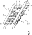
- Fig. 1 shows a first connection module 100a and a second connection module 100b. These are input / output signal and / or functional devices of automation technology for use in an automation device.
- the first connection module 100a and the second connection module 100b are designed as sensor / actuator boxes for signal conditioning near the machine in an automation device.
- the first connection module 100a has eight connections 102, which in the present exemplary embodiment are designed as M12 connections and in the present exemplary embodiment allow each to connect a sensor or actuator to each of the connections 102 as a functional element.
- the terminals 102 are formed in the present embodiment as a sensor-actuator ports.
- the connection module 100a has four further connections 110, two of which are designed as M12 connections in the present exemplary embodiment.
- sensor signals can be forwarded from the terminals 102 to other components of the automation device.
- the further connections 110 may be, for example, a network or fieldbus connection act, which can also be formed socket-socket connection, eg in Ethernet-based devices.
- one of the further connections 110 is designed as a plug-socket fieldbus interface.
- a connection for a voltage supply in the present exemplary embodiment for a supply and forwarding of electrical energy, can be arranged.
- connection module 100b has eight connections 102, which in the present exemplary embodiment are designed as M8 connections, and in the present exemplary embodiment allow each to connect a sensor or actuator to each of the connections 102 as a functional element.
- the terminals 102 are formed as sensor-actuator ports.
- the connection module 100b has three further connections 110, of which one connection is designed as an M12 connection in the present exemplary embodiment.
- the further connections 110 permit a forwarding of sensor signals from the connections 102 to other components of the automation device.
- the further terminals 110 may be e.g. to act a network or field bus connection, which may also be designed as a socket, e.g. for Ethernet-based devices.
- one of the further connections 110 is designed as a plug of an incoming fieldbus interface.
- a connection for a further fieldbus or for an Ethernet interface and in a third row a connection for a voltage supply can be arranged.
- each of the terminals 102 and each of the further terminals 110 is assigned an operating display 104.
- the operation indicators 104 are for optical signaling of digital signal states, for displaying input / output signal states, for displaying diagnostic states of devices of the automation device and for displaying network states.
- Each operating display 104 has a display element 106, which is accommodated in an opening 108 of a housing 112a, 112b of the connection modules 100a, 100b.
- the housings 112a, 122b are designed to be dust-tight and splash-proof in order to ensure safe operation of the connection modules 100a, 100b in an automation device.
- the housings are made of plastic, for example by means of injection molding.
- the housings 112a, 112b have stopper means 114, which will be explained later.
- the stop means 114 are integrally formed on the housings 112a, 112b.
- the housing 112a, 112b and the stop means 114 in the present embodiment are integrally formed and of uniform material.
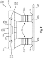
- Fig. 2 shows the schematic structure of the operation display 104 with the display element 106th
- the display element 106 has a base body 200 in the present embodiment.
- the main body 200 in the present embodiment comprises a base portion 202, a first arm portion 204a and a second arm portion 204b.
- the base body 200 comprising the base section 202 and the two arm sections 204, 204b, is manufactured in one piece and of the same material from an optically transparent plastic.
- the base body 200 may be completely or even partially colored optically to provide colored light.
- the first arm portion 204a has a first light coupling surface 206a
- the second arm portion 204b has a second light coupling surface 206b.
- the first light coupling surface 206a is in contact with a light source 218 disposed on a circuit board 226 disposed inside the connection module 100a, 100b.
- the second light coupling-in surface 206b is arranged in contact with another light source 218, which is likewise arranged on the printed circuit board 226.
- the light source 218 is formed as an LED.
- the base portion 202 of the base body 200 has a light output surface 208, wherein the first arm portion 204a and the second arm portion 204b in the base portion 202 unite so that light signals from the first light input surface 206a on the first arm portion 204a and / or the second light input surface 206b be guided at the second arm portion to the light output surface 208.
- the light output surface 208 of the base portion 202 of the main body 200 is a labeling field light input surface 220 of a labeling field element 210 in contact.
- light signals from the light outcoupling surface 208 can be coupled through the caption field light input surface 220 into the caption field element 210, which in turn has a caption field light output surface 224 for emitting the light signals.
- the labeling panel 210 is made of plastic in the present embodiment, e.g. clear plastic. But it can also be made of colored plastic.
- the labeling field 210 has a guide section 212, which is in engagement with a guide 214 of the base body 200.
- the guide 214 is arranged in the base section 202.
- the guide 214 is formed as a groove and the guide portion 212 as a sliding block. By means of the guide section 212 engaging in the guide 214, the labeling field element 210 is securely fastened to the base body 200.
- the guide portion 212 is integrally formed on the labeling field element 210.
- the label field element 210 in the present embodiment has a label 220 that contains information about e.g. represents the functional element connected to the terminal 102.
- the label 220 may be applied by printing on the label panel 210 or by surface removal of material, e.g. by milling or by laser treatment.
- the base body 200 in the present embodiment on the two arm portions 204, 205 arranged latching elements 216 which are formed in the present embodiment as around the two arm portions 204a, 204b circumferential rings that dip into the opening 108 and lock there with correspondingly shaped opening portions to secure the display element 106 securely to the terminal module 100a, 100b.
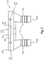
- the Fig. 3 to 5 show the main body 200 with the base portion 202, the two arm portions 204a, 204b as well as with the attached to the base 200 Labeling field element 210 in a side view, a plan view and another side view.
- the Fig. 6 to 8 show the main body 200, the base portion 202 and the arm portions 204a, 204b with the attached label field element 210 in various perspective views.
- the Fig. 6 to 8 show further that the guide portion 212 and the guide 214 define a first mounting direction I, so that by displacing the Beschriftungsfeldelements 210 in this direction, the labeling field element 210 can be attached to the main body 200. For this purpose, it is necessary in advance to bring the guide 214 with the guide portion 212 into engagement. By displacing in a second mounting direction II, the base body 200 with the labeling field element 210 is then fastened to the connection module 100a, 100b by displacing the two arm sections 206a, 204b in the opening 108 in the direction of the second mounting direction II.
- the base body 200 with the labeling field element 210 When the base body 200 with the labeling field element 210 has reached its end position in the opening 108, it is achieved by the corresponding design of the opening 108 that a displacement of the labeling field element 210 in the guide 214 in the assembly direction I by stop means 114, e.g. a peripheral around the opening 108 edge is blocked. Thus, the labeling panel 210 can not accidentally fall out or come off. Since, in the present embodiment, the first mounting direction I is at right angles to the second mounting direction II, a particularly simple intuitive assembly is given.
- light signals from the light sources 218 on the board 226 are coupled through the two light coupling surfaces 206a, 206b into the arm sections 204a, 204b and forwarded to the base section 204 of the main body 200. Then, the light signals emerge from the light output surface 208 and through the caption field light input surface 220 into the caption field element 210, where they exit through the caption field light output surface 224 and illuminate a caption 220.
- the operation indicator 104 is used in the present embodiment, the optical signaling of digital signal states, for displaying input / output signal states, for displaying diagnostic states of devices of the automation device and for displaying network conditions.
- the base body By displacing in a second mounting direction II, the base body can be removed, and by moving in the direction of the first mounting direction, the labeling field element 210 can be removed, for example, to change the label 220 or change the labeling field element 210 with another labeling field element 210 with a replace other label 220.
- the labeling field element 210 By displacing in a second mounting direction II, the base body can be removed, and by moving in the direction of the first mounting direction, the labeling field element 210 can be removed, for example, to change the label 220 or change the labeling field element 210 with another labeling field element 210 with a replace other label 220.
Landscapes
- Physics & Mathematics (AREA)
- Engineering & Computer Science (AREA)
- Microelectronics & Electronic Packaging (AREA)
- Optics & Photonics (AREA)
- Illuminated Signs And Luminous Advertising (AREA)
- Optical Couplings Of Light Guides (AREA)
- Securing Globes, Refractors, Reflectors Or The Like (AREA)
- Planar Illumination Modules (AREA)
Claims (10)
- Module de raccordement (100a, 100b) avec une pluralité de raccords (102) pour des éléments fonctionnels, et avec une pluralité d'indicateurs de fonctionnement (104), dans lequel au moins un des indicateurs de fonctionnement (104) présente un élément indicateur (106), dans lequel l'élément indicateur (106) présente un corps de base (200) réalisé en tant que conducteur de lumière avec une surface d'entrée de lumière (206a, 206b) et une surface de sortie de lumière (208) ;
dans lequel l'élément indicateur (106) présente un élément de champ d'inscription (210) ;
dans lequel l'élément de champ d'inscription (210) présente une surface d'entrée de lumière de champ d'inscription (220), et dans lequel la surface d'entrée de lumière de champ d'inscription (220) est en contact photoconducteur avec la surface de sortie de lumière (208) ; et
dans lequel l'élément de champ d'inscription (210) présente une section de guidage (212), qui est en prise avec un guidage (214) du corps de base (200). - Module de raccordement (100a, 100b) selon la revendication 1,
dans lequel l'élément de champ d'inscription (210) présente une inscription (220). - Module de raccordement (100a, 100b) selon la revendication 1 ou 2, dans lequel la section de guidage (212) et le guidage (214) définissent un premier sens de montage (I) pour le montage de l'élément de champ d'inscription (210) sur le corps de base (200), dans lequel le premier sens de montage (I) se distingue d'un second sens de montage (II) pour le montage de l'élément indicateur (106) sur le module de raccordement (100).
- Module de raccordement (100a, 100b) selon la revendication 3,
dans lequel le premier sens de montage (I) et le second sens de montage (II) sont agencés en angle droit l'un par rapport à l'autre. - Module de raccordement (100a, 100b) selon l'une quelconque des revendications précédentes, dans lequel le corps de base (200) présente une section de base (202) avec la surface de sortie de lumière (202) et au moins deux sections de bras (204a, 204b) se raccordant au corps de base (200) avec respectivement une surface d'entrée de lumière (206a, 206b).
- Module de raccordement (100a, 100b) selon la revendication 5,
dans lequel la section de base (202) et les deux sections de bras (204a, 204b) sont réalisées d'un seul tenant et/ou dans le même matériau. - Module de raccordement (100a, 100b) selon l'une quelconque des revendications précédentes, dans lequel le corps de base (200) est fabriqué en plastique.
- Module de raccordement (100a, 100b) selon l'une quelconque des revendications précédentes, dans lequel le module de raccordement (100a, 100b) présente un boîtier (112a, 112b) avec une ouverture (108), et dans lequel le corps de base (200) présente un élément d'encliquetage (216), qui plonge dans l'ouverture (108) et s'y enclenche avec des sections d'ouverture réalisées de manière correspondante, afin de fixer l'élément indicateur (106) sur le module de raccordement (100a, 100b).
- Module de raccordement (100a, 100b) selon l'une quelconque des revendications précédentes, dans lequel le module de raccordement (100a, 100b) présente une ouverture (108), dans laquelle l'élément indicateur (106) est reçu au moins en partie.
- Module de raccordement (100a, 100b) selon l'une quelconque des revendications précédentes, dans lequel le module de raccordement (100a, 100b) présente une source de lumière (218) émettant des signaux lumineux dans la surface d'entrée de lumière (206a, 206b).
Applications Claiming Priority (2)
| Application Number | Priority Date | Filing Date | Title |
|---|---|---|---|
| DE102013100987.5A DE102013100987B4 (de) | 2013-01-31 | 2013-01-31 | Anschlussmodul |
| PCT/EP2014/050578 WO2014117996A1 (fr) | 2013-01-31 | 2014-01-14 | Module de raccordement pourvu d'un affichage lumineux |
Publications (2)
| Publication Number | Publication Date |
|---|---|
| EP2951059A1 EP2951059A1 (fr) | 2015-12-09 |
| EP2951059B1 true EP2951059B1 (fr) | 2018-09-05 |
Family
ID=49989718
Family Applications (1)
| Application Number | Title | Priority Date | Filing Date |
|---|---|---|---|
| EP14700626.6A Active EP2951059B1 (fr) | 2013-01-31 | 2014-01-14 | Module de raccordement avec indicateurs lumineux |
Country Status (6)
| Country | Link |
|---|---|
| US (1) | US9812821B2 (fr) |
| EP (1) | EP2951059B1 (fr) |
| JP (1) | JP2016508622A (fr) |
| CN (1) | CN104968530B (fr) |
| DE (1) | DE102013100987B4 (fr) |
| WO (1) | WO2014117996A1 (fr) |
Families Citing this family (7)
| Publication number | Priority date | Publication date | Assignee | Title |
|---|---|---|---|---|
| JP7065377B2 (ja) * | 2016-06-30 | 2022-05-12 | パナソニックIpマネジメント株式会社 | 配線器具 |
| US10347092B2 (en) | 2016-07-28 | 2019-07-09 | Banner Engineering Corp. | Omni-directional in-line illumination indicator device |
| US10971861B2 (en) * | 2017-02-24 | 2021-04-06 | Michael S. Gzybowski | Polarized electrical plug and adaptor with modular orientation verification |
| USD918149S1 (en) | 2019-01-09 | 2021-05-04 | Wago Verwaltungsgesellschaft Mbh | Control device |
| US11705679B2 (en) | 2020-12-18 | 2023-07-18 | Banner Engineering Corp. | In-line modular indicator assembly |
| WO2023086838A1 (fr) * | 2021-11-11 | 2023-05-19 | Preddio Technologies Inc. | Accessoire d'identification de contact pour connecteurs électriques |
| EP4636368A1 (fr) | 2024-04-16 | 2025-10-22 | Murrelektronik GmbH | Procédé de détection d'au moins une action d'installation dans une installation industrielle |
Family Cites Families (38)
| Publication number | Priority date | Publication date | Assignee | Title |
|---|---|---|---|---|
| US3262224A (en) * | 1960-12-07 | 1966-07-26 | George K C Hardesty | Composite illumination device |
| US3582927A (en) * | 1969-06-30 | 1971-06-01 | Lester Associates Inc | Power network display panels and controls |
| JPS5018463Y1 (fr) * | 1970-02-09 | 1975-06-05 | ||
| JPS537665Y2 (fr) * | 1972-06-26 | 1978-02-27 | ||
| JPS5521052Y2 (fr) * | 1974-03-18 | 1980-05-21 | ||
| DE4102448A1 (de) * | 1991-01-28 | 1992-07-30 | Siemens Ag | Elektronisches geraet mit leuchtdioden |
| US5212899A (en) * | 1991-06-27 | 1993-05-25 | Gerhard Fandreyer | Switch plate labelling assembly |
| US5263271A (en) | 1991-07-01 | 1993-11-23 | Honeywell Inc. | Annumciator with improved deadfront effect and improve light distribution uniformity |
| DE4122118C2 (de) * | 1991-07-04 | 1997-04-24 | Abb Patent Gmbh | Schriftfeldbeleuchtung |
| JP2850968B2 (ja) * | 1992-06-18 | 1999-01-27 | 株式会社ダイフク | 表示装置 |
| US5613874A (en) * | 1995-05-05 | 1997-03-25 | Ortronics Inc. | Snap-in designation strip for modular information management oulet |
| US5818343A (en) * | 1996-11-29 | 1998-10-06 | Northern Telecom Limited | Redundantly coded visual indication system |
| DE19709529A1 (de) | 1997-03-10 | 1998-09-24 | Grunwald Hans Dieter | Display für Werbe- und Hinweis-Aussagen |
| US6026605A (en) * | 1998-10-28 | 2000-02-22 | Tippett; Nancy J. | Switch plate picture frame assembly |
| US6172301B1 (en) * | 1999-07-14 | 2001-01-09 | Hubbell Incorporated | Receptacle faceplate |
| DE19957611A1 (de) | 1999-11-30 | 2001-06-07 | Osram Opto Semiconductors Gmbh | Beleuchtungsanordnung |
| US6593530B2 (en) * | 2001-07-26 | 2003-07-15 | Torrence L. Hunt | Electrical switch identification plate with replaceable insert members |
| US6718674B2 (en) * | 2002-03-21 | 2004-04-13 | Panduit Corp. | Apparatus and system for identification labeling |
| AU2002952186A0 (en) * | 2002-10-22 | 2002-10-31 | Edney, Neil Frederick | Tagging animals |
| JP4222056B2 (ja) * | 2003-02-24 | 2009-02-12 | 市光工業株式会社 | 車両用灯具 |
| DE602004026108D1 (de) * | 2003-11-07 | 2010-04-29 | Mpathx Llc | Automatische mess-leistungssysteme und verfahren |
| DE102004056247B4 (de) | 2004-11-22 | 2012-12-20 | Abb Ag | Anzeigeeinrichtung für ein Elektronikgerät |
| US7654023B2 (en) * | 2005-04-11 | 2010-02-02 | Mark Peters | Backlit static display on foam board using light piping pegs as highlighters |
| US20080102708A1 (en) * | 2006-10-31 | 2008-05-01 | June-On Co., Ltd. | Kvm switch |
| US7503790B2 (en) | 2007-07-03 | 2009-03-17 | Rockwell Automation Technologies, Inc. | Industrial automation input output module with elastomeric sealing |
| US20090051558A1 (en) * | 2007-08-20 | 2009-02-26 | Tellabs Bedford, Inc. | Method and apparatus for providing optical indications about a state of a circuit |
| US7578085B1 (en) * | 2008-02-01 | 2009-08-25 | Albert Chao | Solar powered address indicator with rechargeable and replaceable batteries |
| EP2106001A1 (fr) * | 2008-03-28 | 2009-09-30 | Hugo Brennenstuhl GmbH & Co. KG | Agencement de prise |
| DE102008036373A1 (de) * | 2008-08-05 | 2010-02-11 | Hager Electro Gmbh & Co. Kg | Verteilerkasten |
| DE102009006793A1 (de) | 2009-01-30 | 2010-08-05 | Phoenix Contact Gmbh & Co. Kg | Multifunktionsvorrichtung zur Konfektionierung von Markierungsschildern |
| US8698606B2 (en) * | 2009-10-28 | 2014-04-15 | Lg Innotek Co., Ltd. | Digital price displayer and ESL system comprising the same |
| DE102010040534A1 (de) * | 2010-09-10 | 2012-03-15 | Robert Bosch Gmbh | Lichtleitungssystem für eine Anzeigeeinrichtung und Anzeigeeinrichtung |
| JP2012216429A (ja) * | 2011-03-31 | 2012-11-08 | Sharp Corp | 光源モジュールおよびそれを備えた電子機器 |
| JP5794675B2 (ja) * | 2011-06-01 | 2015-10-14 | キヤノン株式会社 | 表示板の取付け構造並びに雲台装置及びカメラ装置 |
| CN104081239A (zh) * | 2012-01-31 | 2014-10-01 | 惠普发展公司,有限责任合伙企业 | 连接器检测 |
| US9078051B2 (en) * | 2013-02-18 | 2015-07-07 | Commscope, Inc. Of North Carolina | Intelligent patching systems and components thereof |
| US20140317978A1 (en) * | 2013-04-29 | 2014-10-30 | Kyung Tae Kim | Electric Wiring Device Marking System |
| US9083123B2 (en) * | 2013-06-26 | 2015-07-14 | Tait Towers Manufacturing, LLC | Visually evident connection system for plug-in power/data cable |
-
2013
- 2013-01-31 DE DE102013100987.5A patent/DE102013100987B4/de active Active
-
2014
- 2014-01-14 WO PCT/EP2014/050578 patent/WO2014117996A1/fr not_active Ceased
- 2014-01-14 US US14/764,660 patent/US9812821B2/en active Active
- 2014-01-14 JP JP2015555627A patent/JP2016508622A/ja active Pending
- 2014-01-14 CN CN201480006583.7A patent/CN104968530B/zh active Active
- 2014-01-14 EP EP14700626.6A patent/EP2951059B1/fr active Active
Also Published As
| Publication number | Publication date |
|---|---|
| US9812821B2 (en) | 2017-11-07 |
| CN104968530A (zh) | 2015-10-07 |
| CN104968530B (zh) | 2017-09-08 |
| DE102013100987A1 (de) | 2014-07-31 |
| DE102013100987B4 (de) | 2023-06-29 |
| JP2016508622A (ja) | 2016-03-22 |
| WO2014117996A1 (fr) | 2014-08-07 |
| EP2951059A1 (fr) | 2015-12-09 |
| US20150372432A1 (en) | 2015-12-24 |
Similar Documents
| Publication | Publication Date | Title |
|---|---|---|
| DE102013100987B4 (de) | Anschlussmodul | |
| DE69423764T2 (de) | Eingabe/Ausgabe-Einrichtung | |
| EP2065986B1 (fr) | Unité de prise | |
| DE202015009802U1 (de) | Vorrichtung zum Laden eines elektrisch betreibbaren Fahrzeugs | |
| DE202008017697U1 (de) | Steckverbinder und Steckbuchse für Telekommunikations- oder Datenkabel | |
| DE102021122319A1 (de) | Steckverbinderteil zum Verbinden mit einem Gegensteckverbinderteil | |
| EP1610422A1 (fr) | Dispositif de connexion électrique | |
| DE102014213792A1 (de) | Elektronische Benutzerschnittstelle mit einer separaten Steuerplatine und Haushaltsgerät mit einer solchen Benutzerschnittstelle | |
| EP1107389A1 (fr) | Dispositif d'éclairage pour un véhicule | |
| EP2654317B1 (fr) | Composant d'entrée/de sortie doté d'un élément d'affichage | |
| DE102022116608A1 (de) | Steckverbindermodul für den Leiterplattenanschluss und Verteilerbox mit einem Steckverbindermodul | |
| EP2400608B1 (fr) | Appareil de communication de fabrication modulaire pour mise en réseau et signalisation avec appareils de commande et de signalisation | |
| DE102021105132A1 (de) | Verriegelungsvorrichtung zum Ausleuchten der Steckerkontur einer Ladedose eines elektrischen Fahrzeugs | |
| DE4309049C2 (de) | Optisches Schaltelement | |
| DE102022120756B4 (de) | Kabelgebundener Sensor mit Signalanzeige im Kabelmantel der Anschlussleitung | |
| DE102017130750A1 (de) | Steckverbindersystem | |
| EP4096035A1 (fr) | Connecteur ethernet à paire unique | |
| EP1384221B1 (fr) | Systeme d'affichage | |
| DE102010052632A1 (de) | Modulanordnung mit mehreren in einer Reihe aneinander angeordneten elektrischen Modulen | |
| DE202011052067U1 (de) | Anzeigevorrichtung für einen Sensor und Sensorvorrichtung | |
| DE202016104346U1 (de) | Flexibles erweiterbares Automatisierungsgerät | |
| DE102013102598B3 (de) | Elektrisches/elektronisches Installationsgerät | |
| DE102004044544A1 (de) | Vorrichtung zur Beleuchtung der Bedienungsblende einer Waschmaschine über das Elektronikgehäuse | |
| DE102004056247B4 (de) | Anzeigeeinrichtung für ein Elektronikgerät | |
| DE102024114507A1 (de) | Beleuchtungseinheit |
Legal Events
| Date | Code | Title | Description |
|---|---|---|---|
| PUAI | Public reference made under article 153(3) epc to a published international application that has entered the european phase |
Free format text: ORIGINAL CODE: 0009012 |
|
| 17P | Request for examination filed |
Effective date: 20150717 |
|
| AK | Designated contracting states |
Kind code of ref document: A1 Designated state(s): AL AT BE BG CH CY CZ DE DK EE ES FI FR GB GR HR HU IE IS IT LI LT LU LV MC MK MT NL NO PL PT RO RS SE SI SK SM TR |
|
| AX | Request for extension of the european patent |
Extension state: BA ME |
|
| DAX | Request for extension of the european patent (deleted) | ||
| REG | Reference to a national code |
Ref country code: DE Ref legal event code: R079 Ref document number: 502014009374 Country of ref document: DE Free format text: PREVIOUS MAIN CLASS: B60Q0003040000 Ipc: F21V0008000000 |
|
| GRAP | Despatch of communication of intention to grant a patent |
Free format text: ORIGINAL CODE: EPIDOSNIGR1 |
|
| STAA | Information on the status of an ep patent application or granted ep patent |
Free format text: STATUS: GRANT OF PATENT IS INTENDED |
|
| RIC1 | Information provided on ipc code assigned before grant |
Ipc: H01R 12/00 20060101ALI20180323BHEP Ipc: H01R 13/717 20060101ALI20180323BHEP Ipc: G08B 5/36 20060101ALI20180323BHEP Ipc: F21V 8/00 20060101AFI20180323BHEP |
|
| INTG | Intention to grant announced |
Effective date: 20180420 |
|
| GRAS | Grant fee paid |
Free format text: ORIGINAL CODE: EPIDOSNIGR3 |
|
| GRAA | (expected) grant |
Free format text: ORIGINAL CODE: 0009210 |
|
| STAA | Information on the status of an ep patent application or granted ep patent |
Free format text: STATUS: THE PATENT HAS BEEN GRANTED |
|
| AK | Designated contracting states |
Kind code of ref document: B1 Designated state(s): AL AT BE BG CH CY CZ DE DK EE ES FI FR GB GR HR HU IE IS IT LI LT LU LV MC MK MT NL NO PL PT RO RS SE SI SK SM TR |
|
| REG | Reference to a national code |
Ref country code: GB Ref legal event code: FG4D Free format text: NOT ENGLISH |
|
| REG | Reference to a national code |
Ref country code: CH Ref legal event code: EP |
|
| REG | Reference to a national code |
Ref country code: AT Ref legal event code: REF Ref document number: 1038237 Country of ref document: AT Kind code of ref document: T Effective date: 20180915 |
|
| REG | Reference to a national code |
Ref country code: DE Ref legal event code: R096 Ref document number: 502014009374 Country of ref document: DE |
|
| REG | Reference to a national code |
Ref country code: IE Ref legal event code: FG4D Free format text: LANGUAGE OF EP DOCUMENT: GERMAN |
|
| REG | Reference to a national code |
Ref country code: NL Ref legal event code: MP Effective date: 20180905 |
|
| REG | Reference to a national code |
Ref country code: LT Ref legal event code: MG4D |
|
| PG25 | Lapsed in a contracting state [announced via postgrant information from national office to epo] |
Ref country code: FI Free format text: LAPSE BECAUSE OF FAILURE TO SUBMIT A TRANSLATION OF THE DESCRIPTION OR TO PAY THE FEE WITHIN THE PRESCRIBED TIME-LIMIT Effective date: 20180905 Ref country code: GR Free format text: LAPSE BECAUSE OF FAILURE TO SUBMIT A TRANSLATION OF THE DESCRIPTION OR TO PAY THE FEE WITHIN THE PRESCRIBED TIME-LIMIT Effective date: 20181206 Ref country code: NO Free format text: LAPSE BECAUSE OF FAILURE TO SUBMIT A TRANSLATION OF THE DESCRIPTION OR TO PAY THE FEE WITHIN THE PRESCRIBED TIME-LIMIT Effective date: 20181205 Ref country code: RS Free format text: LAPSE BECAUSE OF FAILURE TO SUBMIT A TRANSLATION OF THE DESCRIPTION OR TO PAY THE FEE WITHIN THE PRESCRIBED TIME-LIMIT Effective date: 20180905 Ref country code: LT Free format text: LAPSE BECAUSE OF FAILURE TO SUBMIT A TRANSLATION OF THE DESCRIPTION OR TO PAY THE FEE WITHIN THE PRESCRIBED TIME-LIMIT Effective date: 20180905 Ref country code: SE Free format text: LAPSE BECAUSE OF FAILURE TO SUBMIT A TRANSLATION OF THE DESCRIPTION OR TO PAY THE FEE WITHIN THE PRESCRIBED TIME-LIMIT Effective date: 20180905 Ref country code: BG Free format text: LAPSE BECAUSE OF FAILURE TO SUBMIT A TRANSLATION OF THE DESCRIPTION OR TO PAY THE FEE WITHIN THE PRESCRIBED TIME-LIMIT Effective date: 20181205 |
|
| PG25 | Lapsed in a contracting state [announced via postgrant information from national office to epo] |
Ref country code: AL Free format text: LAPSE BECAUSE OF FAILURE TO SUBMIT A TRANSLATION OF THE DESCRIPTION OR TO PAY THE FEE WITHIN THE PRESCRIBED TIME-LIMIT Effective date: 20180905 Ref country code: LV Free format text: LAPSE BECAUSE OF FAILURE TO SUBMIT A TRANSLATION OF THE DESCRIPTION OR TO PAY THE FEE WITHIN THE PRESCRIBED TIME-LIMIT Effective date: 20180905 Ref country code: HR Free format text: LAPSE BECAUSE OF FAILURE TO SUBMIT A TRANSLATION OF THE DESCRIPTION OR TO PAY THE FEE WITHIN THE PRESCRIBED TIME-LIMIT Effective date: 20180905 |
|
| PG25 | Lapsed in a contracting state [announced via postgrant information from national office to epo] |
Ref country code: ES Free format text: LAPSE BECAUSE OF FAILURE TO SUBMIT A TRANSLATION OF THE DESCRIPTION OR TO PAY THE FEE WITHIN THE PRESCRIBED TIME-LIMIT Effective date: 20180905 Ref country code: NL Free format text: LAPSE BECAUSE OF FAILURE TO SUBMIT A TRANSLATION OF THE DESCRIPTION OR TO PAY THE FEE WITHIN THE PRESCRIBED TIME-LIMIT Effective date: 20180905 Ref country code: PL Free format text: LAPSE BECAUSE OF FAILURE TO SUBMIT A TRANSLATION OF THE DESCRIPTION OR TO PAY THE FEE WITHIN THE PRESCRIBED TIME-LIMIT Effective date: 20180905 Ref country code: IS Free format text: LAPSE BECAUSE OF FAILURE TO SUBMIT A TRANSLATION OF THE DESCRIPTION OR TO PAY THE FEE WITHIN THE PRESCRIBED TIME-LIMIT Effective date: 20190105 Ref country code: RO Free format text: LAPSE BECAUSE OF FAILURE TO SUBMIT A TRANSLATION OF THE DESCRIPTION OR TO PAY THE FEE WITHIN THE PRESCRIBED TIME-LIMIT Effective date: 20180905 Ref country code: CZ Free format text: LAPSE BECAUSE OF FAILURE TO SUBMIT A TRANSLATION OF THE DESCRIPTION OR TO PAY THE FEE WITHIN THE PRESCRIBED TIME-LIMIT Effective date: 20180905 Ref country code: EE Free format text: LAPSE BECAUSE OF FAILURE TO SUBMIT A TRANSLATION OF THE DESCRIPTION OR TO PAY THE FEE WITHIN THE PRESCRIBED TIME-LIMIT Effective date: 20180905 Ref country code: IT Free format text: LAPSE BECAUSE OF FAILURE TO SUBMIT A TRANSLATION OF THE DESCRIPTION OR TO PAY THE FEE WITHIN THE PRESCRIBED TIME-LIMIT Effective date: 20180905 |
|
| PG25 | Lapsed in a contracting state [announced via postgrant information from national office to epo] |
Ref country code: SM Free format text: LAPSE BECAUSE OF FAILURE TO SUBMIT A TRANSLATION OF THE DESCRIPTION OR TO PAY THE FEE WITHIN THE PRESCRIBED TIME-LIMIT Effective date: 20180905 Ref country code: SK Free format text: LAPSE BECAUSE OF FAILURE TO SUBMIT A TRANSLATION OF THE DESCRIPTION OR TO PAY THE FEE WITHIN THE PRESCRIBED TIME-LIMIT Effective date: 20180905 Ref country code: PT Free format text: LAPSE BECAUSE OF FAILURE TO SUBMIT A TRANSLATION OF THE DESCRIPTION OR TO PAY THE FEE WITHIN THE PRESCRIBED TIME-LIMIT Effective date: 20190105 |
|
| REG | Reference to a national code |
Ref country code: DE Ref legal event code: R097 Ref document number: 502014009374 Country of ref document: DE |
|
| PLBE | No opposition filed within time limit |
Free format text: ORIGINAL CODE: 0009261 |
|
| STAA | Information on the status of an ep patent application or granted ep patent |
Free format text: STATUS: NO OPPOSITION FILED WITHIN TIME LIMIT |
|
| PG25 | Lapsed in a contracting state [announced via postgrant information from national office to epo] |
Ref country code: DK Free format text: LAPSE BECAUSE OF FAILURE TO SUBMIT A TRANSLATION OF THE DESCRIPTION OR TO PAY THE FEE WITHIN THE PRESCRIBED TIME-LIMIT Effective date: 20180905 |
|
| 26N | No opposition filed |
Effective date: 20190606 |
|
| PG25 | Lapsed in a contracting state [announced via postgrant information from national office to epo] |
Ref country code: SI Free format text: LAPSE BECAUSE OF FAILURE TO SUBMIT A TRANSLATION OF THE DESCRIPTION OR TO PAY THE FEE WITHIN THE PRESCRIBED TIME-LIMIT Effective date: 20180905 Ref country code: MC Free format text: LAPSE BECAUSE OF FAILURE TO SUBMIT A TRANSLATION OF THE DESCRIPTION OR TO PAY THE FEE WITHIN THE PRESCRIBED TIME-LIMIT Effective date: 20180905 |
|
| REG | Reference to a national code |
Ref country code: CH Ref legal event code: PL |
|
| GBPC | Gb: european patent ceased through non-payment of renewal fee |
Effective date: 20190114 |
|
| PG25 | Lapsed in a contracting state [announced via postgrant information from national office to epo] |
Ref country code: LU Free format text: LAPSE BECAUSE OF NON-PAYMENT OF DUE FEES Effective date: 20190114 |
|
| REG | Reference to a national code |
Ref country code: BE Ref legal event code: MM Effective date: 20190131 |
|
| REG | Reference to a national code |
Ref country code: IE Ref legal event code: MM4A |
|
| PG25 | Lapsed in a contracting state [announced via postgrant information from national office to epo] |
Ref country code: FR Free format text: LAPSE BECAUSE OF NON-PAYMENT OF DUE FEES Effective date: 20190131 |
|
| PG25 | Lapsed in a contracting state [announced via postgrant information from national office to epo] |
Ref country code: BE Free format text: LAPSE BECAUSE OF NON-PAYMENT OF DUE FEES Effective date: 20190131 |
|
| PG25 | Lapsed in a contracting state [announced via postgrant information from national office to epo] |
Ref country code: LI Free format text: LAPSE BECAUSE OF NON-PAYMENT OF DUE FEES Effective date: 20190131 Ref country code: CH Free format text: LAPSE BECAUSE OF NON-PAYMENT OF DUE FEES Effective date: 20190131 Ref country code: GB Free format text: LAPSE BECAUSE OF NON-PAYMENT OF DUE FEES Effective date: 20190114 |
|
| PG25 | Lapsed in a contracting state [announced via postgrant information from national office to epo] |
Ref country code: IE Free format text: LAPSE BECAUSE OF NON-PAYMENT OF DUE FEES Effective date: 20190114 |
|
| REG | Reference to a national code |
Ref country code: AT Ref legal event code: MM01 Ref document number: 1038237 Country of ref document: AT Kind code of ref document: T Effective date: 20190114 |
|
| PG25 | Lapsed in a contracting state [announced via postgrant information from national office to epo] |
Ref country code: TR Free format text: LAPSE BECAUSE OF FAILURE TO SUBMIT A TRANSLATION OF THE DESCRIPTION OR TO PAY THE FEE WITHIN THE PRESCRIBED TIME-LIMIT Effective date: 20180905 |
|
| PG25 | Lapsed in a contracting state [announced via postgrant information from national office to epo] |
Ref country code: AT Free format text: LAPSE BECAUSE OF NON-PAYMENT OF DUE FEES Effective date: 20190114 |
|
| PG25 | Lapsed in a contracting state [announced via postgrant information from national office to epo] |
Ref country code: MT Free format text: LAPSE BECAUSE OF FAILURE TO SUBMIT A TRANSLATION OF THE DESCRIPTION OR TO PAY THE FEE WITHIN THE PRESCRIBED TIME-LIMIT Effective date: 20180905 |
|
| PG25 | Lapsed in a contracting state [announced via postgrant information from national office to epo] |
Ref country code: CY Free format text: LAPSE BECAUSE OF FAILURE TO SUBMIT A TRANSLATION OF THE DESCRIPTION OR TO PAY THE FEE WITHIN THE PRESCRIBED TIME-LIMIT Effective date: 20180905 |
|
| PG25 | Lapsed in a contracting state [announced via postgrant information from national office to epo] |
Ref country code: HU Free format text: LAPSE BECAUSE OF FAILURE TO SUBMIT A TRANSLATION OF THE DESCRIPTION OR TO PAY THE FEE WITHIN THE PRESCRIBED TIME-LIMIT; INVALID AB INITIO Effective date: 20140114 |
|
| PG25 | Lapsed in a contracting state [announced via postgrant information from national office to epo] |
Ref country code: MK Free format text: LAPSE BECAUSE OF FAILURE TO SUBMIT A TRANSLATION OF THE DESCRIPTION OR TO PAY THE FEE WITHIN THE PRESCRIBED TIME-LIMIT Effective date: 20180905 |
|
| P01 | Opt-out of the competence of the unified patent court (upc) registered |
Effective date: 20230424 |
|
| PGFP | Annual fee paid to national office [announced via postgrant information from national office to epo] |
Ref country code: DE Payment date: 20260320 Year of fee payment: 13 |