EP2951077B1 - Lenksäule in faserverbundtechnologie, basierend auf pultrusion- und flecht- und/oder wickeltechnologie - Google Patents
Lenksäule in faserverbundtechnologie, basierend auf pultrusion- und flecht- und/oder wickeltechnologie Download PDFInfo
- Publication number
- EP2951077B1 EP2951077B1 EP13776817.2A EP13776817A EP2951077B1 EP 2951077 B1 EP2951077 B1 EP 2951077B1 EP 13776817 A EP13776817 A EP 13776817A EP 2951077 B1 EP2951077 B1 EP 2951077B1
- Authority
- EP
- European Patent Office
- Prior art keywords
- steering column
- steering
- fibers
- pultrusion
- component
- Prior art date
- Legal status (The legal status is an assumption and is not a legal conclusion. Google has not performed a legal analysis and makes no representation as to the accuracy of the status listed.)
- Not-in-force
Links
- 238000009954 braiding Methods 0.000 title claims description 24
- 239000002131 composite material Substances 0.000 title claims description 22
- 238000004804 winding Methods 0.000 title claims description 12
- 238000005516 engineering process Methods 0.000 title description 7
- 239000000835 fiber Substances 0.000 claims description 45
- 238000000034 method Methods 0.000 claims description 30
- 230000008569 process Effects 0.000 claims description 18
- 229920005989 resin Polymers 0.000 claims description 16
- 239000011347 resin Substances 0.000 claims description 16
- 239000012783 reinforcing fiber Substances 0.000 claims description 8
- 239000003365 glass fiber Substances 0.000 claims description 5
- 239000000463 material Substances 0.000 claims description 5
- 229920000049 Carbon (fiber) Polymers 0.000 claims description 4
- 239000004917 carbon fiber Substances 0.000 claims description 4
- 230000033001 locomotion Effects 0.000 claims description 3
- 239000002759 woven fabric Substances 0.000 claims description 3
- 239000003733 fiber-reinforced composite Substances 0.000 claims description 2
- 229910052751 metal Inorganic materials 0.000 claims description 2
- 239000002184 metal Substances 0.000 claims description 2
- 230000004907 flux Effects 0.000 claims 1
- 230000002093 peripheral effect Effects 0.000 claims 1
- 238000013461 design Methods 0.000 description 7
- 238000004519 manufacturing process Methods 0.000 description 6
- 230000007246 mechanism Effects 0.000 description 6
- 239000004744 fabric Substances 0.000 description 5
- 238000000465 moulding Methods 0.000 description 3
- 238000007493 shaping process Methods 0.000 description 3
- 229910000831 Steel Inorganic materials 0.000 description 2
- 229910052782 aluminium Inorganic materials 0.000 description 2
- XAGFODPZIPBFFR-UHFFFAOYSA-N aluminium Chemical compound [Al] XAGFODPZIPBFFR-UHFFFAOYSA-N 0.000 description 2
- 230000015572 biosynthetic process Effects 0.000 description 2
- 238000011161 development Methods 0.000 description 2
- 230000018109 developmental process Effects 0.000 description 2
- 238000009434 installation Methods 0.000 description 2
- 239000011159 matrix material Substances 0.000 description 2
- VNWKTOKETHGBQD-UHFFFAOYSA-N methane Chemical compound C VNWKTOKETHGBQD-UHFFFAOYSA-N 0.000 description 2
- 239000010959 steel Substances 0.000 description 2
- 239000000057 synthetic resin Substances 0.000 description 2
- 229920003002 synthetic resin Polymers 0.000 description 2
- 229920001169 thermoplastic Polymers 0.000 description 2
- 229920001187 thermosetting polymer Polymers 0.000 description 2
- 239000004416 thermosoftening plastic Substances 0.000 description 2
- OKTJSMMVPCPJKN-UHFFFAOYSA-N Carbon Chemical compound [C] OKTJSMMVPCPJKN-UHFFFAOYSA-N 0.000 description 1
- 229920002430 Fibre-reinforced plastic Polymers 0.000 description 1
- FYYHWMGAXLPEAU-UHFFFAOYSA-N Magnesium Chemical compound [Mg] FYYHWMGAXLPEAU-UHFFFAOYSA-N 0.000 description 1
- 229920005830 Polyurethane Foam Polymers 0.000 description 1
- 230000009471 action Effects 0.000 description 1
- 239000000853 adhesive Substances 0.000 description 1
- 230000001070 adhesive effect Effects 0.000 description 1
- 239000004760 aramid Substances 0.000 description 1
- 229920003235 aromatic polyamide Polymers 0.000 description 1
- 230000000712 assembly Effects 0.000 description 1
- 238000000429 assembly Methods 0.000 description 1
- 238000005452 bending Methods 0.000 description 1
- 230000008901 benefit Effects 0.000 description 1
- 230000005540 biological transmission Effects 0.000 description 1
- 229910052799 carbon Inorganic materials 0.000 description 1
- 239000000969 carrier Substances 0.000 description 1
- 238000005266 casting Methods 0.000 description 1
- 238000007596 consolidation process Methods 0.000 description 1
- 238000005260 corrosion Methods 0.000 description 1
- 230000007797 corrosion Effects 0.000 description 1
- 230000001419 dependent effect Effects 0.000 description 1
- 230000002349 favourable effect Effects 0.000 description 1
- 239000011151 fibre-reinforced plastic Substances 0.000 description 1
- 239000000446 fuel Substances 0.000 description 1
- 239000011521 glass Substances 0.000 description 1
- 230000012447 hatching Effects 0.000 description 1
- 239000007788 liquid Substances 0.000 description 1
- 229910052749 magnesium Inorganic materials 0.000 description 1
- 239000011777 magnesium Substances 0.000 description 1
- 239000007769 metal material Substances 0.000 description 1
- 239000004848 polyfunctional curative Substances 0.000 description 1
- 229920000642 polymer Polymers 0.000 description 1
- 239000011496 polyurethane foam Substances 0.000 description 1
- 238000012545 processing Methods 0.000 description 1
- 238000000926 separation method Methods 0.000 description 1
- 238000009958 sewing Methods 0.000 description 1
- 238000007711 solidification Methods 0.000 description 1
- 230000008023 solidification Effects 0.000 description 1
- 238000003860 storage Methods 0.000 description 1
- 239000004616 structural foam Substances 0.000 description 1
- 238000002604 ultrasonography Methods 0.000 description 1
- 238000011144 upstream manufacturing Methods 0.000 description 1
Images




Classifications
-
- B—PERFORMING OPERATIONS; TRANSPORTING
- B29—WORKING OF PLASTICS; WORKING OF SUBSTANCES IN A PLASTIC STATE IN GENERAL
- B29C—SHAPING OR JOINING OF PLASTICS; SHAPING OF MATERIAL IN A PLASTIC STATE, NOT OTHERWISE PROVIDED FOR; AFTER-TREATMENT OF THE SHAPED PRODUCTS, e.g. REPAIRING
- B29C70/00—Shaping composites, i.e. plastics material comprising reinforcements, fillers or preformed parts, e.g. inserts
- B29C70/04—Shaping composites, i.e. plastics material comprising reinforcements, fillers or preformed parts, e.g. inserts comprising reinforcements only, e.g. self-reinforcing plastics
- B29C70/28—Shaping operations therefor
- B29C70/40—Shaping or impregnating by compression not applied
- B29C70/50—Shaping or impregnating by compression not applied for producing articles of indefinite length, e.g. prepregs, sheet moulding compounds [SMC] or cross moulding compounds [XMC]
- B29C70/52—Pultrusion, i.e. forming and compressing by continuously pulling through a die
- B29C70/525—Component parts, details or accessories; Auxiliary operations
-
- B—PERFORMING OPERATIONS; TRANSPORTING
- B29—WORKING OF PLASTICS; WORKING OF SUBSTANCES IN A PLASTIC STATE IN GENERAL
- B29C—SHAPING OR JOINING OF PLASTICS; SHAPING OF MATERIAL IN A PLASTIC STATE, NOT OTHERWISE PROVIDED FOR; AFTER-TREATMENT OF THE SHAPED PRODUCTS, e.g. REPAIRING
- B29C70/00—Shaping composites, i.e. plastics material comprising reinforcements, fillers or preformed parts, e.g. inserts
- B29C70/04—Shaping composites, i.e. plastics material comprising reinforcements, fillers or preformed parts, e.g. inserts comprising reinforcements only, e.g. self-reinforcing plastics
- B29C70/06—Fibrous reinforcements only
- B29C70/08—Fibrous reinforcements only comprising combinations of different forms of fibrous reinforcements incorporated in matrix material, forming one or more layers, and with or without non-reinforced layers
- B29C70/083—Combinations of continuous fibres or fibrous profiled structures oriented in one direction and reinforcements forming a two dimensional structure, e.g. mats
-
- B—PERFORMING OPERATIONS; TRANSPORTING
- B29—WORKING OF PLASTICS; WORKING OF SUBSTANCES IN A PLASTIC STATE IN GENERAL
- B29C—SHAPING OR JOINING OF PLASTICS; SHAPING OF MATERIAL IN A PLASTIC STATE, NOT OTHERWISE PROVIDED FOR; AFTER-TREATMENT OF THE SHAPED PRODUCTS, e.g. REPAIRING
- B29C70/00—Shaping composites, i.e. plastics material comprising reinforcements, fillers or preformed parts, e.g. inserts
- B29C70/04—Shaping composites, i.e. plastics material comprising reinforcements, fillers or preformed parts, e.g. inserts comprising reinforcements only, e.g. self-reinforcing plastics
- B29C70/06—Fibrous reinforcements only
- B29C70/08—Fibrous reinforcements only comprising combinations of different forms of fibrous reinforcements incorporated in matrix material, forming one or more layers, and with or without non-reinforced layers
- B29C70/083—Combinations of continuous fibres or fibrous profiled structures oriented in one direction and reinforcements forming a two dimensional structure, e.g. mats
- B29C70/085—Combinations of continuous fibres or fibrous profiled structures oriented in one direction and reinforcements forming a two dimensional structure, e.g. mats the structure being deformed in a three dimensional configuration
-
- B—PERFORMING OPERATIONS; TRANSPORTING
- B29—WORKING OF PLASTICS; WORKING OF SUBSTANCES IN A PLASTIC STATE IN GENERAL
- B29C—SHAPING OR JOINING OF PLASTICS; SHAPING OF MATERIAL IN A PLASTIC STATE, NOT OTHERWISE PROVIDED FOR; AFTER-TREATMENT OF THE SHAPED PRODUCTS, e.g. REPAIRING
- B29C70/00—Shaping composites, i.e. plastics material comprising reinforcements, fillers or preformed parts, e.g. inserts
- B29C70/04—Shaping composites, i.e. plastics material comprising reinforcements, fillers or preformed parts, e.g. inserts comprising reinforcements only, e.g. self-reinforcing plastics
- B29C70/28—Shaping operations therefor
- B29C70/40—Shaping or impregnating by compression not applied
- B29C70/50—Shaping or impregnating by compression not applied for producing articles of indefinite length, e.g. prepregs, sheet moulding compounds [SMC] or cross moulding compounds [XMC]
- B29C70/52—Pultrusion, i.e. forming and compressing by continuously pulling through a die
-
- B—PERFORMING OPERATIONS; TRANSPORTING
- B29—WORKING OF PLASTICS; WORKING OF SUBSTANCES IN A PLASTIC STATE IN GENERAL
- B29D—PRODUCING PARTICULAR ARTICLES FROM PLASTICS OR FROM SUBSTANCES IN A PLASTIC STATE
- B29D23/00—Producing tubular articles
- B29D23/001—Pipes; Pipe joints
-
- B—PERFORMING OPERATIONS; TRANSPORTING
- B62—LAND VEHICLES FOR TRAVELLING OTHERWISE THAN ON RAILS
- B62D—MOTOR VEHICLES; TRAILERS
- B62D1/00—Steering controls, i.e. means for initiating a change of direction of the vehicle
- B62D1/02—Steering controls, i.e. means for initiating a change of direction of the vehicle vehicle-mounted
- B62D1/16—Steering columns
-
- B—PERFORMING OPERATIONS; TRANSPORTING
- B29—WORKING OF PLASTICS; WORKING OF SUBSTANCES IN A PLASTIC STATE IN GENERAL
- B29K—INDEXING SCHEME ASSOCIATED WITH SUBCLASSES B29B, B29C OR B29D, RELATING TO MOULDING MATERIALS OR TO MATERIALS FOR MOULDS, REINFORCEMENTS, FILLERS OR PREFORMED PARTS, e.g. INSERTS
- B29K2105/00—Condition, form or state of moulded material or of the material to be shaped
- B29K2105/06—Condition, form or state of moulded material or of the material to be shaped containing reinforcements, fillers or inserts
- B29K2105/08—Condition, form or state of moulded material or of the material to be shaped containing reinforcements, fillers or inserts of continuous length, e.g. cords, rovings, mats, fabrics, strands or yarns
- B29K2105/0809—Fabrics
- B29K2105/0827—Braided fabrics
-
- B—PERFORMING OPERATIONS; TRANSPORTING
- B62—LAND VEHICLES FOR TRAVELLING OTHERWISE THAN ON RAILS
- B62D—MOTOR VEHICLES; TRAILERS
- B62D1/00—Steering controls, i.e. means for initiating a change of direction of the vehicle
- B62D1/02—Steering controls, i.e. means for initiating a change of direction of the vehicle vehicle-mounted
- B62D1/16—Steering columns
- B62D1/163—Part of the steering column replaced by flexible means, e.g. cable or belt
-
- Y—GENERAL TAGGING OF NEW TECHNOLOGICAL DEVELOPMENTS; GENERAL TAGGING OF CROSS-SECTIONAL TECHNOLOGIES SPANNING OVER SEVERAL SECTIONS OF THE IPC; TECHNICAL SUBJECTS COVERED BY FORMER USPC CROSS-REFERENCE ART COLLECTIONS [XRACs] AND DIGESTS
- Y10—TECHNICAL SUBJECTS COVERED BY FORMER USPC
- Y10T—TECHNICAL SUBJECTS COVERED BY FORMER US CLASSIFICATION
- Y10T29/00—Metal working
- Y10T29/49—Method of mechanical manufacture
- Y10T29/49826—Assembling or joining
- Y10T29/49828—Progressively advancing of work assembly station or assembled portion of work
Definitions
- the invention relates to a steering column assembly for a vehicle and a method of manufacturing components for such a steering column assembly.
- Generic steering column assemblies or steering columns are installed in the application in a motor vehicle and transmit the applied by the driver on a steering wheel torques in a steering system of the vehicle. Furthermore, steering columns have to withstand a variety of loads during use, especially when the vehicle collides with an obstacle - the crash case.
- the DE 10 2005 034 952 B3 discloses, for example, a steering column which is adjustable in height and inclination.
- a steering shaft is rotatably mounted in a control part, which is also referred to as a shell unit.
- the jacket unit is held in a holding part and the holding part is mounted in a retaining clip which can be fastened to a vehicle body.
- a clamping system is provided which is adjustable between an open position and a closed position with a control lever.
- the jacket unit In the open position of the clamping system, the jacket unit can be moved in its longitudinal direction with respect to the holding part and at the same time the holding part are pivoted in its inclination about a pivot axis relative to the retaining clip. In the closed position of the clamping system is fixed the steering spindle with respect to the body-mounted retaining clip.
- Such steering columns and clamping systems are known in the prior art in various designs.
- a general desire is for the favorable influence of fuel consumption and to improve the driving dynamics of motor vehicles, as well as to increase the range of electric vehicles, such steering columns form particularly easily and with high rigidity.
- the beats DE 101 55 891 B4 generally, the shell unit, which forms the central bearing tube to represent a thermoplastic or a thermoplastic tube with glass or carbon fiber filling.
- the disclosure leaves open how such a bearing tube can be made concrete.
- the EP 0091671 B1 discloses a safety steering column in which a tubular part of the steering shaft is formed integrally with a rigid steering column section made of fiber-reinforced plastic. It is disclosed that the steering column is produced in a winding technique around a core, for example made of rigid polyurethane foam. However, the possibilities for the design of the steering column are severely limited.
- a steering column support housing made of polymer composite material having a mounting bracket is known, wherein the steering column support housing and the mounting bracket have a plurality of fibers within a composite material.
- the disclosure DE 198 09 264 A1 a fiber fabric assembly and method for making a preform.
- individual fiber layers are stacked and sewn with sewing threads, with partially adhesive fleeces are inserted as intermediate layers.
- a meltable layer is introduced, which is activated only in a forming process and ensures after forming into a desired three-dimensional shape for permanent solidification of the preform.
- the object of the invention is to provide a lightweight pillar in which a great deal of design freedom is given.
- a steering column for a motor vehicle having a steering spindle rotatably mounted in a steering spindle bearing unit about a longitudinal axis and with a support unit which is adapted to form the connection of the steering shaft bearing unit with the body of the motor vehicle, at least one component of the steering column at least partially from a fiber-reinforced composite material is further provided, that the component is in the power flow of the steering column between the steering shaft and the body and that at least one pultrusion layer is provided, which has a plurality of reinforcing fibers in the longitudinal axis and mutually parallel aligned pultrusion fibers, creates a large degree at design freedom. So can be dispensed with a core in the production of the fiber composite component. It is also possible to form on the outer surface in the circumferential direction concave areas, which is not or only with great difficulty realized in braiding or winding process
- the carrier formed with the pultrusion can be braided and / or wrapped around its inner surface and / or its outer surface for forming the shaped article.
- the invention is applicable to a steering column assembly which is adjustable in length and / or inclination.
- the support unit is advantageously formed by a holding part, which is connectable to the body of the motor vehicle, and receives a guide bracket which holds the steering shaft bearing unit.
- a fixing system is provided which can be selectively adjusted between an open and a closed position. When the fixing system is open, the steering spindle can be adjusted by preferably the guide clip in a pivot axis in the holding part is pivotable and the steering shaft bearing unit is displaceable in the guide bracket.
- the invention is also applicable to adjustable steering columns, in which the adjustment functions are shown in a different manner, as are known in the art.
- the pultrusion fibers carry at least one gel layer formed of fibers, for example of a woven fabric, a knitted fabric, a knitted fabric or a braid or a wrapping. It is preferred if the gel layer is a tissue, as a particularly good rigidity against torsion can be achieved.
- pultrusion fibers surround the steering spindle shell-like in the circumferential direction by at least 180 °, a geometry advantageous for the subsequent assembly can already be achieved during production of the component, without the component produced having to be subsequently cut open, as is the case with tubular blanks.
- the torsional stiffness is further enhanced when the at least one release layer comprises a woven or braided fabric having greater than 50% portion of fibers oriented within the release layer, these fibers being oriented at an angle between 20 ° and 70 ° to the pultrusion fibers.
- the pultrusion layer is arranged between the release layers and at least one release layer lies on the outside and the at least one other release layer lies inside.
- a good compromise between mechanical properties, weight and cost is achieved by making the at least one outer layer of glass fiber and the pultrusion layer and / or the at least one inner layer of carbon fiber.
- the total weight of the steering column is reduced if the component made of fiber composite material directly or indirectly supports the steering spindle.
- the at least one gel layer integrally formed for example, materially attached or laminated laminated functional elements.
- the functional elements are preferably selected from the group comprising fastening straps, guides, movement limits and holders for harnesses.
- the functional elements can be sheet metal tabs with openings, holes or recesses.
- the component is a guide bracket for the steering shaft bearing unit.
- the attachment of other functional elements of the steering column is simplified if the guide bracket in a central area at one in the Operation overhead side is open.
- a steering lock can be arranged.
- FIG. 1 shows a method of making a fiber composite material component by pultrusion and braiding.
- Fiber composites are materials made of reinforcing fibers, which are embedded in a matrix, whereby the material is extremely lightweight.
- fiber composites generally have a higher specific stiffness than metallic materials.
- the weights of the components can be reduced.
- the rigidity of the components can be increased, for example, to reduce vibrations on the steering wheel, stimulated by the road or the engine, and thus to improve the comfort properties.
- one or more other methods can be upstream or downstream.
- the winding and braiding process is ideal for this.
- the matrix is cured in a tool.
- FIG. 1 is produced by pultrusion (also called pultrusion) and downstream braiding a blank 1 made of fiber composite material.
- pre-impregnated rovings 2 consisting of parallel-arranged, not shown here, pre-impregnated uncured continuous fibers are used.
- the rovings 2 are pulled through a first template 3 and brought into the desired profile shape.
- the tensile force applied by the pulling device is so great that the arrangement of the rovings 2 and thus the profile shape is maintained in the remaining process steps.
- the shaped rovings 2 are guided through a braiding head 4.
- the pultruded profile can be used as a scrim or core and reinforced with one or more wound or braided layers.
- the same result as in the braiding process can also be achieved by winding.
- the rovings are not arranged in a criss-cross directional structure during winding, but are wound all around. Several rovings can be wound in a correspondingly offset manner so that practically the same arrangement of the rovings is created.
- the entire braid is guided through a second template 5 and a third template 6. Subsequently, the braid is pulled through a heated curing section 7.
- the synthetic resin solidifies by the action of heat and forms a blank 1 from.
- the resin is mixed with a hardener. This curing can be done by introducing an elevated temperature and / or by introducing ultrasound and / or by an introduction of ultraviolet light.
- core or mold core 11 can be the molding in the tool be compacted.
- the mandrel 11 extends over the entire distance from the beginning of the pultrusion or the braiding or winding process to curing of the curable resin. This makes it possible to arrange a mesh or a fiber coil around the core within the carrier formed by the pultrusion.
- FIG. 2 another embodiment of the process b) is shown.
- rovings 2 brought by pulling through a first, not shown here template in the profile shape. Thereafter, as in the previous form, by introducing it into the braiding head 4, a second layer of rovings 2 is braided onto the arrangement of the rovings 2.
- the braid passes through the braiding 4 an impregnating bath 8 in which it is impregnated with liquid resin. Subsequently, in a heated curing section 7, which simultaneously forms a tool mold 9, the synthetic resin is cured.
- the intended mold 9 ensures the profile shape and can make further shaping. After curing, the blank 1 is cut or sawn by a separator 10.
- FIG. 3 shows a tool mold 9 with a mold core 11.
- mandrels 11 serve the shaping of the blank 7 and can be used alone or in addition to stencils.
- Reusable mandrels 11 are preferably made of aluminum or steel.
- the mandrel can protrude from the tool on one side and extend to the braiding head 4 or to the first template 3. This arrangement is advantageous or even necessary, especially in the abovementioned processes c) and d).
- mold cores 11 are known from structural foam, which may remain in the fiber composite component or soluble mandrels 11 which are washed out after fiber composite consolidation. However, such cores are not preferable.
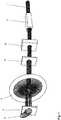
- a schematic representation of the procedure b) is in Fig. 4 played.
- the rovings 2 are unwound and tensioned in a first step by a roller handling 12. Thereafter, they pass through the first template 3 before a braid is applied by the braiding 4 and the entire profile is passed through the second template 5.
- the rovings 2 then pass through the impregnating bath 8, the tool mold 9 and the hardening section 7.
- the resin received in the impregnating bath 8 is hardened in the hardening section 7.
- Behind the curing section 7 is a traction device 13, which in the preceding FIGS. 1 and 2 not shown. By this traction device 13, the rovings 2 are stretched and pulled from left to right through the individual components of the structure.
- the separator 10 ensures that the length of the blank 1 is cut to size.
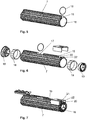
- the blank 1 is in further steps ( Fig. 5-7 ) to a casing tube 14 of a steering column according to the invention completed.
- Fig. 5 is indicated, is introduced for this purpose in a guide web 15 of the blank 7 on a front side 16, a first cutout with an opening.
- a second cutout 17 is introduced on the guide web 15, which can serve in cooperation with other elements as a longitudinal stop of the steering column according to the invention.
- both sides of the blank 1 two bearing receptacles 18 and corresponding bearings 19 are added to the storage of a steering shaft to the blank 1.
- a holder 21 for an immobilizer not shown here is mounted on the first cutout 20 of the guide web 15 on the end face 16 of the blank 1, so that through the opening 22, the immobilizer can engage in a steering shaft, not shown here.
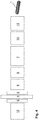
- FIG. 8 a profile of a preferred layer structure of a blank 1 is shown.
- the profile shows the cured resin with embedded rovings 2 in three layers. Hatching is not to be considered Rovings 2.
- the inner layer 23 consists of pultrusion rovings which, in the case of predominantly tensile or bending-loaded components, such as, for example, the jacket tube of a steering column, lie in the axial direction in the component in the direction of flow.
- the outer layers 24, 25 of the layer structure consist of arrangements in braiding or winding technology with an angle of about +/- 45 °.
- All fibers of the layer structure may consist of glass, aramid or carbon. Other materials can also be used to form the fibers.
- the outer layers 24, 25 with glass fibers and the inner layers 23, the pultruded layer are formed with carbon fibers.
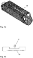
- FIGS. 9 and 10 is a tool mold 9 and a blank 1 an alternative representation of a casing tube 14 illustrated, in which no guide web is provided and the casing tube 14 is formed in a polygonal polygonal shape.
- An advantage of the method according to the invention is that the design of the profile can be chosen freely and thus the design of the jacket tube is not limited.
- FIGS. 11 to 14 illustrate the representation of a guide bracket 26.
- a corresponding blank 1 is produced in combination of pultrusion and braiding and winding technology.
- FIG. 12 an end piece 27, a bearing receptacle 28 and a bearing 29 added for the steering shaft, as well as wedge elements 30 inserted for the clamping system of the steering column in the blank 1.
- FIG. 13 is such a preassembled module shown.
- FIG. 15 an alternative embodiment of the guide clip 26 is shown with the corresponding separations.
- FIG. 16 shows the engagement of a clamping bolt 31 in the guide web 15 which limits the length adjustment with the stops in the open position of the clamping system.
- the individual components of which at least one component has been produced with the described technology, are assembled together.
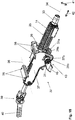
- the Figures 17 and 18 illustrate a steering column 32 according to the invention, which comprises a steering shaft 33 which is rotatably mounted about its axis of rotation 34 in a steering shaft bearing unit 35, comprising a jacket tube 14.
- the jacket tube 14 is slidably guided in a guide bracket 26 along the longitudinal axis 34 of the steering shaft 33.
- the guide bracket 26 is pivotally mounted about a pivot axis 36 in a holding part 37.
- the holding part 37 can be fixed in attachment points 38 on the body, not shown.
- the rotary motion introduced into the steering spindle 33 by a driver via a steering wheel (not shown) is introduced via a cardan joint 39 and further steering shaft parts 40 into the steering gear (not shown).
- the steering column 32 can be adjusted in its height in the adjustment direction 41 and in its length in the adjustment direction 42.
- a fixing mechanism 43 is provided, which comprises a tensioning apparatus known in the prior art.
- the tensioning lever 46 By turning the tensioning lever 46, the two cams of the cam mechanism 44 are rotated against each other and the side cheeks 37a, 37b contracted, whereby a frictional tension of the side cheeks 37a, 37 b of the holding part 37 with the side surfaces of the guide bracket 26 and again done with side surfaces of the casing tube 14.
- the clamping bolt 31 passes through slots in the side cheeks 37a, 37b of the holding part 37 and holes in the side surfaces 26a, 26b of the guide bracket 26.
- the cam mechanism 44 is disposed on the one end of the clamping bolt and the thrust bearing 45 arranged on the other end of the clamping bolt 31.
- the side cheeks 37a, 37b, and the side surfaces 26a, 26b, as well as the jacket tube 14 are disposed between the cam mechanism 44 and the thrust bearing 45.
- the fixing system 43 can be selectively switched to an open position or a closed position.
- the steering spindle 33, or the attached steering wheel (not shown in the figures) can be adjusted in position, in particular in the longitudinal direction 42 and the height or inclination direction 41 are moved.
- the closed position of the fixing system 43 the steering column 32 is fixed in position.
Landscapes
- Engineering & Computer Science (AREA)
- Mechanical Engineering (AREA)
- Chemical & Material Sciences (AREA)
- Composite Materials (AREA)
- Combustion & Propulsion (AREA)
- Transportation (AREA)
- Moulding By Coating Moulds (AREA)
- Steering Controls (AREA)
Priority Applications (1)
| Application Number | Priority Date | Filing Date | Title |
|---|---|---|---|
| PL13776817T PL2951077T3 (pl) | 2013-01-29 | 2013-10-15 | Kolumna kierownicy wytwarzana w technologii kompozytów włóknistych i bazująca na technologii pultruzji oraz technologii oplatania i/lub nawijania |
Applications Claiming Priority (2)
| Application Number | Priority Date | Filing Date | Title |
|---|---|---|---|
| DE102013001442.5A DE102013001442B3 (de) | 2013-01-29 | 2013-01-29 | Lenksäule in Faserverbundtechnologie, basierend auf Pultrusion- und Flecht- und/oder Wickeltechnologie |
| PCT/EP2013/071508 WO2014117876A1 (de) | 2013-01-29 | 2013-10-15 | Lenksäule in faserverbundtechnologie, basierend auf pultrusion- und flecht- und/oder wickeltechnologie |
Publications (2)
| Publication Number | Publication Date |
|---|---|
| EP2951077A1 EP2951077A1 (de) | 2015-12-09 |
| EP2951077B1 true EP2951077B1 (de) | 2017-05-10 |
Family
ID=49356447
Family Applications (1)
| Application Number | Title | Priority Date | Filing Date |
|---|---|---|---|
| EP13776817.2A Not-in-force EP2951077B1 (de) | 2013-01-29 | 2013-10-15 | Lenksäule in faserverbundtechnologie, basierend auf pultrusion- und flecht- und/oder wickeltechnologie |
Country Status (7)
| Country | Link |
|---|---|
| US (2) | US9487227B2 (pl) |
| EP (1) | EP2951077B1 (pl) |
| CN (1) | CN105143016B (pl) |
| DE (1) | DE102013001442B3 (pl) |
| ES (1) | ES2636816T3 (pl) |
| PL (1) | PL2951077T3 (pl) |
| WO (1) | WO2014117876A1 (pl) |
Families Citing this family (18)
| Publication number | Priority date | Publication date | Assignee | Title |
|---|---|---|---|---|
| AT514088B1 (de) * | 2013-06-20 | 2014-10-15 | Thyssenkrupp Presta Ag | Lenksäule für ein Kraftfahrzeug und Verfahren zur Herstellung einer Lenksäule |
| CN113942174B (zh) * | 2014-07-01 | 2025-03-11 | 沙特基础工业全球技术有限公司 | 用于包覆模制纤维增强聚合组件的方法和装置 |
| DE102014011991A1 (de) * | 2014-08-12 | 2016-02-18 | Daimler Ag | Mantelrohr für eine Lenksäule eines Kraftwagens sowie Verfahren zum Herstellen eines solchen Mantelrohrs |
| EP3015256A1 (de) * | 2014-10-27 | 2016-05-04 | Evonik Röhm GmbH | Herstellung mehrere unterschiedlicher Faserverbundbauteile für Großserien in einem kontinuierlichen Prozess |
| DE102014017807B3 (de) * | 2014-12-04 | 2016-03-31 | Freundes- und Förderkreis des Institutes für Textiltechnik der RWTH Aachen e.V. | Flechtpultrusionsanlage |
| DE102015000028A1 (de) * | 2015-01-08 | 2016-07-14 | Thyssenkrupp Ag | Fertigungsverfahren für eine modulare Lenksäule mit Strangpressprofilen |
| DE102015103083A1 (de) | 2015-03-04 | 2016-09-08 | Dr. Ing. H.C. F. Porsche Aktiengesellschaft | Verbundwerkstoff-Stabbauteil und Verfahren zur Herstellung eines Verbundwerkstoff-Stabbauteils |
| DE102015204894A1 (de) | 2015-03-18 | 2016-09-22 | Thyssenkrupp Ag | Lenksäule für ein Kraftfahrzeug |
| DE102015207230B3 (de) | 2015-04-21 | 2016-03-24 | Thyssenkrupp Ag | Lenksäule für ein Kraftfahrzeug |
| KR20160132294A (ko) * | 2015-05-08 | 2016-11-17 | (주)엘지하우시스 | 섬유강화복합소재를 이용한 인서트 사출 성형 방법 및 이를 이용한 사출 성형품 |
| DE102015007784B4 (de) | 2015-06-19 | 2020-02-13 | Thyssenkrupp Ag | Lenksäule mit elektro-mechanischer Fixiervorrichtung |
| DE102015216326B4 (de) | 2015-08-26 | 2016-09-08 | Thyssenkrupp Ag | Motorisch verstellbare Lenksäule für ein Kraftfahrzeug |
| JP2017140722A (ja) * | 2016-02-09 | 2017-08-17 | 本田技研工業株式会社 | 軸状複合部材の製造方法 |
| DE102016106688A1 (de) * | 2016-04-12 | 2017-10-12 | Dr. Ing. H.C. F. Porsche Aktiengesellschaft | Hybridbauteil für ein Fahrzeug |
| US11014792B2 (en) * | 2016-04-19 | 2021-05-25 | Stand Technologies Pty Ltd | Light weight jack stand |
| CN106079483B (zh) * | 2016-07-25 | 2018-05-08 | 威海首创实利进出口有限公司 | 一种超强超韧复合材料杆体及其制造方法 |
| CN114650908B (zh) | 2019-11-15 | 2025-03-25 | 新时代管道私人有限公司 | 管材成型设备 |
| CN111941881A (zh) * | 2020-07-28 | 2020-11-17 | 中复碳芯电缆科技有限公司 | 一种采用拉挤工艺制造用于风机叶片的高模片材制备工艺 |
Family Cites Families (24)
| Publication number | Priority date | Publication date | Assignee | Title |
|---|---|---|---|---|
| US4100013A (en) * | 1976-08-05 | 1978-07-11 | Plastigage Corporation | Apparatus for forming resin embedded antenna |
| US4318762A (en) * | 1980-04-21 | 1982-03-09 | Victor United, Inc. | Method and apparatus for sequentially forming a molded product |
| DE3213462A1 (de) * | 1982-04-10 | 1983-10-13 | Audi Nsu Auto Union Ag, 7107 Neckarsulm | Sicherheitslenksaeule fuer kraftfahrzeuge |
| DE3321198C1 (de) * | 1983-06-11 | 1984-11-29 | Messerschmitt-Bölkow-Blohm GmbH, 8000 München | Sicherheitslenksaeule aus gewickelten faserverstaerkten Kunststoffen |
| US5028357A (en) * | 1989-08-14 | 1991-07-02 | Ceramic Cooling Tower Company | Lightweight cooling tower with cruciform columns |
| US5580627A (en) * | 1993-12-20 | 1996-12-03 | Goodwin; Stephen L. | Molded products made from preforms of tubular braids |
| US5904972A (en) * | 1995-06-07 | 1999-05-18 | Tpi Technology Inc. | Large composite core structures formed by vacuum assisted resin transfer molding |
| EP0996563A1 (de) * | 1997-07-15 | 2000-05-03 | Krupp Presta Aktiengesellschaft | Lenksäulenanordnung für kraftfahrzeuge mit energieabsorptionselement |
| FR2768205B1 (fr) * | 1997-09-05 | 1999-10-29 | Lemforder Nacam Sa | Securite d'engagement a etrier d'un dispositif de maintien en position d'un systeme de serrage de deux elements |
| DE19809264C2 (de) * | 1998-03-04 | 2003-06-26 | Eldra Kunststofftechnik Gmbh | Fasergelegeanordnung und Verfahren zur Herstellung eines Vorformlings |
| GB2368894B (en) | 2000-11-14 | 2005-07-20 | Nastech Europ Ltd | Steering column assembly for a vehicle |
| US8419883B2 (en) * | 2000-12-27 | 2013-04-16 | Milliken & Company | Fiber reinforced composite cores and panels |
| US6692026B2 (en) * | 2001-09-13 | 2004-02-17 | Visteon Global Technologies, Inc. | Polymer composite steering column support housing and assembly |
| US7972698B2 (en) * | 2004-10-21 | 2011-07-05 | Graftech International Holdings Inc. | Carbon foam core panels |
| DE102005034952B3 (de) * | 2005-07-22 | 2007-02-22 | Thyssenkrupp Automotive Ag | Verstellbare Lenksäule für ein Kraftfahrzeug |
| CN1919587A (zh) * | 2005-08-25 | 2007-02-28 | 深圳市海川实业股份有限公司 | 一种增加纤维增强树脂拉挤型材横向强度的方法及其产品 |
| DE102008014206B3 (de) * | 2008-01-16 | 2009-09-17 | Tedrive Holding B.V. | Drehmomentsensierung mittels integrierten Dehnungsmessstreifen |
| CN102256858B (zh) * | 2008-12-19 | 2014-12-10 | C.劳勃.汉默斯坦两合有限公司 | 具有支撑部和转向柱的用于机动车辆的长度可调节的转向致动单元 |
| CN101708657B (zh) * | 2009-10-26 | 2012-05-23 | 南京诺尔泰复合材料设备制造有限公司 | 复合材料多层斜拉缠绕生产方法及其生产线 |
| DE102012000633A1 (de) * | 2012-01-14 | 2013-07-18 | Daimler Ag | Konsolenelement zur Halterung einer Lenksäule eines Kraftwagens sowie Verfahren zum Herstellen eines solchen Konsolenelements |
| DE102012005434B3 (de) * | 2012-03-20 | 2013-04-18 | Thyssenkrupp Presta Ag | Lenksäule mit im Flechtverfahren hergestellten Faserverbundelementen |
| DE102012007005B4 (de) * | 2012-04-10 | 2014-01-09 | Thyssenkrupp Presta Aktiengesellschaft | Leichtbaulenksäule aus Faserverbundwerkstoff |
| DE102012021493A1 (de) * | 2012-10-31 | 2014-04-30 | Daimler Ag | Querträgeranordnung und Herstellungsverfahren |
| AT514088B1 (de) * | 2013-06-20 | 2014-10-15 | Thyssenkrupp Presta Ag | Lenksäule für ein Kraftfahrzeug und Verfahren zur Herstellung einer Lenksäule |
-
2013
- 2013-01-29 DE DE102013001442.5A patent/DE102013001442B3/de not_active Expired - Fee Related
- 2013-10-15 US US14/764,305 patent/US9487227B2/en not_active Expired - Fee Related
- 2013-10-15 CN CN201380071773.2A patent/CN105143016B/zh not_active Expired - Fee Related
- 2013-10-15 WO PCT/EP2013/071508 patent/WO2014117876A1/de not_active Ceased
- 2013-10-15 EP EP13776817.2A patent/EP2951077B1/de not_active Not-in-force
- 2013-10-15 ES ES13776817.2T patent/ES2636816T3/es active Active
- 2013-10-15 PL PL13776817T patent/PL2951077T3/pl unknown
-
2016
- 2016-09-29 US US15/279,667 patent/US10137649B2/en not_active Expired - Fee Related
Also Published As
| Publication number | Publication date |
|---|---|
| WO2014117876A1 (de) | 2014-08-07 |
| US10137649B2 (en) | 2018-11-27 |
| US20150367876A1 (en) | 2015-12-24 |
| ES2636816T3 (es) | 2017-10-09 |
| US20170015071A1 (en) | 2017-01-19 |
| CN105143016A (zh) | 2015-12-09 |
| EP2951077A1 (de) | 2015-12-09 |
| CN105143016B (zh) | 2017-11-28 |
| DE102013001442B3 (de) | 2014-03-13 |
| PL2951077T3 (pl) | 2017-11-30 |
| US9487227B2 (en) | 2016-11-08 |
Similar Documents
| Publication | Publication Date | Title |
|---|---|---|
| DE102013001442B3 (de) | Lenksäule in Faserverbundtechnologie, basierend auf Pultrusion- und Flecht- und/oder Wickeltechnologie | |
| EP3010779B1 (de) | Lenksäule für ein kraftfahrzeug und verfahren zur herstellung einer lenksäule | |
| DE102012007005B4 (de) | Leichtbaulenksäule aus Faserverbundwerkstoff | |
| EP0561151B1 (de) | Verfahren zur Herstellung von Trägern aus faserverstärkten Kunststoffen für Kraftfahrzeug-Stossfänger sowie derartige Träger | |
| EP2828140B1 (de) | Lenksäule mit im flechtverfahren hergestellten faserverbundelementen | |
| DE10240395A1 (de) | Querträger für ein Kraftfahrzeug | |
| DE102011011577A1 (de) | Verfahren zum Herstellen einer Drehstabfeder oder eines Wankstabilisator | |
| DE102009019236A1 (de) | Verfahren zur Herstellung eines Faserverbundbauteils sowie Faserverbundbauteil | |
| WO2009149778A1 (de) | Rohbaustruktur für einen kraftwagen und verfahren zu deren herstellung | |
| DE60206020T2 (de) | Seitenelement für Fahrzeugrahmen und Verfahren für dessen Herstellung | |
| DE102010049563A1 (de) | Verfahren zum Herstellen einer Drehstabfeder | |
| EP2999616B1 (de) | Achsträger eines fahrzeugs | |
| DE102010053732A1 (de) | Drehstabfeder oder Wankstabilisator für ein Kraftfahrzeug sowie Verfahren zu deren Herstellung | |
| EP2626218B1 (de) | Verfahren zum Herstellen einer Radfelge aus Faserverbundwerkstoff und Radfelge für ein Kraftfahrzeug | |
| DE102016106688A1 (de) | Hybridbauteil für ein Fahrzeug | |
| WO2018095664A1 (de) | Verfahren zur herstellung eines lenkers, sowie lenker und radaufhängung | |
| DE102014011991A1 (de) | Mantelrohr für eine Lenksäule eines Kraftwagens sowie Verfahren zum Herstellen eines solchen Mantelrohrs | |
| DE102013005570A1 (de) | Verfahren zur Herstellung eines Bauteils für ein Kraftfahrzeug | |
| DE20221554U1 (de) | Querträger für ein Kraftfahrzeug | |
| DE102013111693A1 (de) | Verfahren zur Herstellung eines Formteils aus einem Faserverbundwerkstoff | |
| DE102016008193A1 (de) | Getriebeträger für einen Kraftwagen |
Legal Events
| Date | Code | Title | Description |
|---|---|---|---|
| PUAI | Public reference made under article 153(3) epc to a published international application that has entered the european phase |
Free format text: ORIGINAL CODE: 0009012 |
|
| 17P | Request for examination filed |
Effective date: 20150624 |
|
| AK | Designated contracting states |
Kind code of ref document: A1 Designated state(s): AL AT BE BG CH CY CZ DE DK EE ES FI FR GB GR HR HU IE IS IT LI LT LU LV MC MK MT NL NO PL PT RO RS SE SI SK SM TR |
|
| AX | Request for extension of the european patent |
Extension state: BA ME |
|
| DAX | Request for extension of the european patent (deleted) | ||
| RAP1 | Party data changed (applicant data changed or rights of an application transferred) |
Owner name: THYSSENKRUPP AG Owner name: THYSSENKRUPP PRESTA AG |
|
| GRAP | Despatch of communication of intention to grant a patent |
Free format text: ORIGINAL CODE: EPIDOSNIGR1 |
|
| INTG | Intention to grant announced |
Effective date: 20161215 |
|
| GRAS | Grant fee paid |
Free format text: ORIGINAL CODE: EPIDOSNIGR3 |
|
| GRAA | (expected) grant |
Free format text: ORIGINAL CODE: 0009210 |
|
| AK | Designated contracting states |
Kind code of ref document: B1 Designated state(s): AL AT BE BG CH CY CZ DE DK EE ES FI FR GB GR HR HU IE IS IT LI LT LU LV MC MK MT NL NO PL PT RO RS SE SI SK SM TR |
|
| REG | Reference to a national code |
Ref country code: GB Ref legal event code: FG4D Free format text: NOT ENGLISH |
|
| REG | Reference to a national code |
Ref country code: AT Ref legal event code: REF Ref document number: 891999 Country of ref document: AT Kind code of ref document: T Effective date: 20170515 Ref country code: CH Ref legal event code: EP |
|
| REG | Reference to a national code |
Ref country code: IE Ref legal event code: FG4D Free format text: LANGUAGE OF EP DOCUMENT: GERMAN |
|
| RAP2 | Party data changed (patent owner data changed or rights of a patent transferred) |
Owner name: THYSSENKRUPP PRESTA AG Owner name: THYSSENKRUPP AG |
|
| REG | Reference to a national code |
Ref country code: DE Ref legal event code: R096 Ref document number: 502013007245 Country of ref document: DE |
|
| REG | Reference to a national code |
Ref country code: DE Ref legal event code: R081 Ref document number: 502013007245 Country of ref document: DE Owner name: THYSSENKRUPP PRESTA AKTIENGESELLSCHAFT, LI Free format text: FORMER OWNERS: THYSSENKRUPP AG, 45143 ESSEN, DE; THYSSENKRUPP PRESTA AG, ESCHEN, LI Ref country code: DE Ref legal event code: R081 Ref document number: 502013007245 Country of ref document: DE Owner name: THYSSENKRUPP AG, DE Free format text: FORMER OWNERS: THYSSENKRUPP AG, 45143 ESSEN, DE; THYSSENKRUPP PRESTA AG, ESCHEN, LI Ref country code: DE Ref legal event code: R081 Ref document number: 502013007245 Country of ref document: DE Owner name: THYSSENKRUPP PRESTA AG, LI Free format text: FORMER OWNERS: THYSSENKRUPP AG, 45143 ESSEN, DE; THYSSENKRUPP PRESTA AG, ESCHEN, LI |
|
| REG | Reference to a national code |
Ref country code: NL Ref legal event code: MP Effective date: 20170510 |
|
| REG | Reference to a national code |
Ref country code: LT Ref legal event code: MG4D |
|
| REG | Reference to a national code |
Ref country code: ES Ref legal event code: FG2A Ref document number: 2636816 Country of ref document: ES Kind code of ref document: T3 Effective date: 20171009 |
|
| REG | Reference to a national code |
Ref country code: FR Ref legal event code: PLFP Year of fee payment: 5 |
|
| PG25 | Lapsed in a contracting state [announced via postgrant information from national office to epo] |
Ref country code: FI Free format text: LAPSE BECAUSE OF FAILURE TO SUBMIT A TRANSLATION OF THE DESCRIPTION OR TO PAY THE FEE WITHIN THE PRESCRIBED TIME-LIMIT Effective date: 20170510 Ref country code: HR Free format text: LAPSE BECAUSE OF FAILURE TO SUBMIT A TRANSLATION OF THE DESCRIPTION OR TO PAY THE FEE WITHIN THE PRESCRIBED TIME-LIMIT Effective date: 20170510 Ref country code: LT Free format text: LAPSE BECAUSE OF FAILURE TO SUBMIT A TRANSLATION OF THE DESCRIPTION OR TO PAY THE FEE WITHIN THE PRESCRIBED TIME-LIMIT Effective date: 20170510 Ref country code: GR Free format text: LAPSE BECAUSE OF FAILURE TO SUBMIT A TRANSLATION OF THE DESCRIPTION OR TO PAY THE FEE WITHIN THE PRESCRIBED TIME-LIMIT Effective date: 20170811 Ref country code: NO Free format text: LAPSE BECAUSE OF FAILURE TO SUBMIT A TRANSLATION OF THE DESCRIPTION OR TO PAY THE FEE WITHIN THE PRESCRIBED TIME-LIMIT Effective date: 20170810 |
|
| PG25 | Lapsed in a contracting state [announced via postgrant information from national office to epo] |
Ref country code: RS Free format text: LAPSE BECAUSE OF FAILURE TO SUBMIT A TRANSLATION OF THE DESCRIPTION OR TO PAY THE FEE WITHIN THE PRESCRIBED TIME-LIMIT Effective date: 20170510 Ref country code: LV Free format text: LAPSE BECAUSE OF FAILURE TO SUBMIT A TRANSLATION OF THE DESCRIPTION OR TO PAY THE FEE WITHIN THE PRESCRIBED TIME-LIMIT Effective date: 20170510 Ref country code: NL Free format text: LAPSE BECAUSE OF FAILURE TO SUBMIT A TRANSLATION OF THE DESCRIPTION OR TO PAY THE FEE WITHIN THE PRESCRIBED TIME-LIMIT Effective date: 20170510 Ref country code: SE Free format text: LAPSE BECAUSE OF FAILURE TO SUBMIT A TRANSLATION OF THE DESCRIPTION OR TO PAY THE FEE WITHIN THE PRESCRIBED TIME-LIMIT Effective date: 20170510 Ref country code: IS Free format text: LAPSE BECAUSE OF FAILURE TO SUBMIT A TRANSLATION OF THE DESCRIPTION OR TO PAY THE FEE WITHIN THE PRESCRIBED TIME-LIMIT Effective date: 20170910 Ref country code: BG Free format text: LAPSE BECAUSE OF FAILURE TO SUBMIT A TRANSLATION OF THE DESCRIPTION OR TO PAY THE FEE WITHIN THE PRESCRIBED TIME-LIMIT Effective date: 20170810 |
|
| PG25 | Lapsed in a contracting state [announced via postgrant information from national office to epo] |
Ref country code: RO Free format text: LAPSE BECAUSE OF FAILURE TO SUBMIT A TRANSLATION OF THE DESCRIPTION OR TO PAY THE FEE WITHIN THE PRESCRIBED TIME-LIMIT Effective date: 20170510 Ref country code: SK Free format text: LAPSE BECAUSE OF FAILURE TO SUBMIT A TRANSLATION OF THE DESCRIPTION OR TO PAY THE FEE WITHIN THE PRESCRIBED TIME-LIMIT Effective date: 20170510 Ref country code: DK Free format text: LAPSE BECAUSE OF FAILURE TO SUBMIT A TRANSLATION OF THE DESCRIPTION OR TO PAY THE FEE WITHIN THE PRESCRIBED TIME-LIMIT Effective date: 20170510 Ref country code: EE Free format text: LAPSE BECAUSE OF FAILURE TO SUBMIT A TRANSLATION OF THE DESCRIPTION OR TO PAY THE FEE WITHIN THE PRESCRIBED TIME-LIMIT Effective date: 20170510 |
|
| REG | Reference to a national code |
Ref country code: DE Ref legal event code: R097 Ref document number: 502013007245 Country of ref document: DE |
|
| PG25 | Lapsed in a contracting state [announced via postgrant information from national office to epo] |
Ref country code: SM Free format text: LAPSE BECAUSE OF FAILURE TO SUBMIT A TRANSLATION OF THE DESCRIPTION OR TO PAY THE FEE WITHIN THE PRESCRIBED TIME-LIMIT Effective date: 20170510 |
|
| PLBE | No opposition filed within time limit |
Free format text: ORIGINAL CODE: 0009261 |
|
| STAA | Information on the status of an ep patent application or granted ep patent |
Free format text: STATUS: NO OPPOSITION FILED WITHIN TIME LIMIT |
|
| 26N | No opposition filed |
Effective date: 20180213 |
|
| PG25 | Lapsed in a contracting state [announced via postgrant information from national office to epo] |
Ref country code: SI Free format text: LAPSE BECAUSE OF FAILURE TO SUBMIT A TRANSLATION OF THE DESCRIPTION OR TO PAY THE FEE WITHIN THE PRESCRIBED TIME-LIMIT Effective date: 20170510 Ref country code: MC Free format text: LAPSE BECAUSE OF FAILURE TO SUBMIT A TRANSLATION OF THE DESCRIPTION OR TO PAY THE FEE WITHIN THE PRESCRIBED TIME-LIMIT Effective date: 20170510 |
|
| REG | Reference to a national code |
Ref country code: CH Ref legal event code: PL |
|
| REG | Reference to a national code |
Ref country code: IE Ref legal event code: MM4A |
|
| PG25 | Lapsed in a contracting state [announced via postgrant information from national office to epo] |
Ref country code: LU Free format text: LAPSE BECAUSE OF NON-PAYMENT OF DUE FEES Effective date: 20171015 Ref country code: CH Free format text: LAPSE BECAUSE OF NON-PAYMENT OF DUE FEES Effective date: 20171031 Ref country code: LI Free format text: LAPSE BECAUSE OF NON-PAYMENT OF DUE FEES Effective date: 20171031 |
|
| REG | Reference to a national code |
Ref country code: BE Ref legal event code: MM Effective date: 20171031 |
|
| PG25 | Lapsed in a contracting state [announced via postgrant information from national office to epo] |
Ref country code: BE Free format text: LAPSE BECAUSE OF NON-PAYMENT OF DUE FEES Effective date: 20171031 |
|
| PG25 | Lapsed in a contracting state [announced via postgrant information from national office to epo] |
Ref country code: MT Free format text: LAPSE BECAUSE OF FAILURE TO SUBMIT A TRANSLATION OF THE DESCRIPTION OR TO PAY THE FEE WITHIN THE PRESCRIBED TIME-LIMIT Effective date: 20170510 |
|
| REG | Reference to a national code |
Ref country code: FR Ref legal event code: PLFP Year of fee payment: 6 |
|
| PG25 | Lapsed in a contracting state [announced via postgrant information from national office to epo] |
Ref country code: IE Free format text: LAPSE BECAUSE OF NON-PAYMENT OF DUE FEES Effective date: 20171015 |
|
| PG25 | Lapsed in a contracting state [announced via postgrant information from national office to epo] |
Ref country code: HU Free format text: LAPSE BECAUSE OF FAILURE TO SUBMIT A TRANSLATION OF THE DESCRIPTION OR TO PAY THE FEE WITHIN THE PRESCRIBED TIME-LIMIT; INVALID AB INITIO Effective date: 20131015 |
|
| PG25 | Lapsed in a contracting state [announced via postgrant information from national office to epo] |
Ref country code: CY Free format text: LAPSE BECAUSE OF FAILURE TO SUBMIT A TRANSLATION OF THE DESCRIPTION OR TO PAY THE FEE WITHIN THE PRESCRIBED TIME-LIMIT Effective date: 20170510 |
|
| PG25 | Lapsed in a contracting state [announced via postgrant information from national office to epo] |
Ref country code: MK Free format text: LAPSE BECAUSE OF FAILURE TO SUBMIT A TRANSLATION OF THE DESCRIPTION OR TO PAY THE FEE WITHIN THE PRESCRIBED TIME-LIMIT Effective date: 20170510 |
|
| PGFP | Annual fee paid to national office [announced via postgrant information from national office to epo] |
Ref country code: PL Payment date: 20190925 Year of fee payment: 7 |
|
| REG | Reference to a national code |
Ref country code: AT Ref legal event code: MM01 Ref document number: 891999 Country of ref document: AT Kind code of ref document: T Effective date: 20181015 |
|
| PG25 | Lapsed in a contracting state [announced via postgrant information from national office to epo] |
Ref country code: AT Free format text: LAPSE BECAUSE OF NON-PAYMENT OF DUE FEES Effective date: 20181015 |
|
| PGFP | Annual fee paid to national office [announced via postgrant information from national office to epo] |
Ref country code: CZ Payment date: 20191011 Year of fee payment: 7 |
|
| PGFP | Annual fee paid to national office [announced via postgrant information from national office to epo] |
Ref country code: ES Payment date: 20191126 Year of fee payment: 7 Ref country code: IT Payment date: 20191028 Year of fee payment: 7 |
|
| PG25 | Lapsed in a contracting state [announced via postgrant information from national office to epo] |
Ref country code: TR Free format text: LAPSE BECAUSE OF FAILURE TO SUBMIT A TRANSLATION OF THE DESCRIPTION OR TO PAY THE FEE WITHIN THE PRESCRIBED TIME-LIMIT Effective date: 20170510 |
|
| PG25 | Lapsed in a contracting state [announced via postgrant information from national office to epo] |
Ref country code: PT Free format text: LAPSE BECAUSE OF FAILURE TO SUBMIT A TRANSLATION OF THE DESCRIPTION OR TO PAY THE FEE WITHIN THE PRESCRIBED TIME-LIMIT Effective date: 20170510 |
|
| PG25 | Lapsed in a contracting state [announced via postgrant information from national office to epo] |
Ref country code: AL Free format text: LAPSE BECAUSE OF FAILURE TO SUBMIT A TRANSLATION OF THE DESCRIPTION OR TO PAY THE FEE WITHIN THE PRESCRIBED TIME-LIMIT Effective date: 20170510 |
|
| PG25 | Lapsed in a contracting state [announced via postgrant information from national office to epo] |
Ref country code: CZ Free format text: LAPSE BECAUSE OF NON-PAYMENT OF DUE FEES Effective date: 20201015 |
|
| PG25 | Lapsed in a contracting state [announced via postgrant information from national office to epo] |
Ref country code: IT Free format text: LAPSE BECAUSE OF NON-PAYMENT OF DUE FEES Effective date: 20201015 |
|
| REG | Reference to a national code |
Ref country code: DE Ref legal event code: R081 Ref document number: 502013007245 Country of ref document: DE Owner name: THYSSENKRUPP PRESTA AKTIENGESELLSCHAFT, LI Free format text: FORMER OWNERS: THYSSENKRUPP AG, 45143 ESSEN, DE; THYSSENKRUPP PRESTA AG, ESCHEN, LI Ref country code: DE Ref legal event code: R081 Ref document number: 502013007245 Country of ref document: DE Owner name: THYSSENKRUPP AG, DE Free format text: FORMER OWNERS: THYSSENKRUPP AG, 45143 ESSEN, DE; THYSSENKRUPP PRESTA AG, ESCHEN, LI |
|
| REG | Reference to a national code |
Ref country code: ES Ref legal event code: FD2A Effective date: 20220121 |
|
| PGFP | Annual fee paid to national office [announced via postgrant information from national office to epo] |
Ref country code: GB Payment date: 20211022 Year of fee payment: 9 |
|
| PGFP | Annual fee paid to national office [announced via postgrant information from national office to epo] |
Ref country code: FR Payment date: 20211022 Year of fee payment: 9 |
|
| PG25 | Lapsed in a contracting state [announced via postgrant information from national office to epo] |
Ref country code: ES Free format text: LAPSE BECAUSE OF NON-PAYMENT OF DUE FEES Effective date: 20201016 |
|
| REG | Reference to a national code |
Ref country code: DE Ref legal event code: R084 Ref document number: 502013007245 Country of ref document: DE |
|
| PGFP | Annual fee paid to national office [announced via postgrant information from national office to epo] |
Ref country code: DE Payment date: 20221019 Year of fee payment: 10 |
|
| PG25 | Lapsed in a contracting state [announced via postgrant information from national office to epo] |
Ref country code: PL Free format text: LAPSE BECAUSE OF NON-PAYMENT OF DUE FEES Effective date: 20201015 |
|
| GBPC | Gb: european patent ceased through non-payment of renewal fee |
Effective date: 20221015 |
|
| PG25 | Lapsed in a contracting state [announced via postgrant information from national office to epo] |
Ref country code: FR Free format text: LAPSE BECAUSE OF NON-PAYMENT OF DUE FEES Effective date: 20221031 |
|
| PG25 | Lapsed in a contracting state [announced via postgrant information from national office to epo] |
Ref country code: GB Free format text: LAPSE BECAUSE OF NON-PAYMENT OF DUE FEES Effective date: 20221015 |
|
| REG | Reference to a national code |
Ref country code: DE Ref legal event code: R119 Ref document number: 502013007245 Country of ref document: DE |
|
| PG25 | Lapsed in a contracting state [announced via postgrant information from national office to epo] |
Ref country code: DE Free format text: LAPSE BECAUSE OF NON-PAYMENT OF DUE FEES Effective date: 20240501 |