EP2951397B1 - Turbomaschinenrotorschaufel - Google Patents
Turbomaschinenrotorschaufel Download PDFInfo
- Publication number
- EP2951397B1 EP2951397B1 EP14705841.6A EP14705841A EP2951397B1 EP 2951397 B1 EP2951397 B1 EP 2951397B1 EP 14705841 A EP14705841 A EP 14705841A EP 2951397 B1 EP2951397 B1 EP 2951397B1
- Authority
- EP
- European Patent Office
- Prior art keywords
- seal lip
- cup
- wear material
- blade
- rotor blade
- Prior art date
- Legal status (The legal status is an assumption and is not a legal conclusion. Google has not performed a legal analysis and makes no representation as to the accuracy of the status listed.)
- Active
Links
Images



Classifications
-
- F—MECHANICAL ENGINEERING; LIGHTING; HEATING; WEAPONS; BLASTING
- F01—MACHINES OR ENGINES IN GENERAL; ENGINE PLANTS IN GENERAL; STEAM ENGINES
- F01D—NON-POSITIVE DISPLACEMENT MACHINES OR ENGINES, e.g. STEAM TURBINES
- F01D5/00—Blades; Blade-carrying members; Heating, heat-insulating, cooling or antivibration means on the blades or the members
- F01D5/12—Blades
- F01D5/22—Blade-to-blade connections, e.g. for damping vibrations
- F01D5/225—Blade-to-blade connections, e.g. for damping vibrations by shrouding
-
- F—MECHANICAL ENGINEERING; LIGHTING; HEATING; WEAPONS; BLASTING
- F01—MACHINES OR ENGINES IN GENERAL; ENGINE PLANTS IN GENERAL; STEAM ENGINES
- F01D—NON-POSITIVE DISPLACEMENT MACHINES OR ENGINES, e.g. STEAM TURBINES
- F01D11/00—Preventing or minimising internal leakage of working-fluid, e.g. between stages
- F01D11/08—Preventing or minimising internal leakage of working-fluid, e.g. between stages for sealing space between rotor blade tips and stator
-
- F—MECHANICAL ENGINEERING; LIGHTING; HEATING; WEAPONS; BLASTING
- F01—MACHINES OR ENGINES IN GENERAL; ENGINE PLANTS IN GENERAL; STEAM ENGINES
- F01D—NON-POSITIVE DISPLACEMENT MACHINES OR ENGINES, e.g. STEAM TURBINES
- F01D5/00—Blades; Blade-carrying members; Heating, heat-insulating, cooling or antivibration means on the blades or the members
- F01D5/12—Blades
- F01D5/28—Selecting particular materials; Particular measures relating thereto; Measures against erosion or corrosion
- F01D5/286—Particular treatment of blades, e.g. to increase durability or resistance against corrosion or erosion
-
- F—MECHANICAL ENGINEERING; LIGHTING; HEATING; WEAPONS; BLASTING
- F01—MACHINES OR ENGINES IN GENERAL; ENGINE PLANTS IN GENERAL; STEAM ENGINES
- F01D—NON-POSITIVE DISPLACEMENT MACHINES OR ENGINES, e.g. STEAM TURBINES
- F01D5/00—Blades; Blade-carrying members; Heating, heat-insulating, cooling or antivibration means on the blades or the members
- F01D5/12—Blades
- F01D5/28—Selecting particular materials; Particular measures relating thereto; Measures against erosion or corrosion
- F01D5/288—Protective coatings for blades
-
- F—MECHANICAL ENGINEERING; LIGHTING; HEATING; WEAPONS; BLASTING
- F05—INDEXING SCHEMES RELATING TO ENGINES OR PUMPS IN VARIOUS SUBCLASSES OF CLASSES F01-F04
- F05D—INDEXING SCHEME FOR ASPECTS RELATING TO NON-POSITIVE-DISPLACEMENT MACHINES OR ENGINES, GAS-TURBINES OR JET-PROPULSION PLANTS
- F05D2220/00—Application
- F05D2220/30—Application in turbines
-
- F—MECHANICAL ENGINEERING; LIGHTING; HEATING; WEAPONS; BLASTING
- F05—INDEXING SCHEMES RELATING TO ENGINES OR PUMPS IN VARIOUS SUBCLASSES OF CLASSES F01-F04
- F05D—INDEXING SCHEME FOR ASPECTS RELATING TO NON-POSITIVE-DISPLACEMENT MACHINES OR ENGINES, GAS-TURBINES OR JET-PROPULSION PLANTS
- F05D2230/00—Manufacture
- F05D2230/10—Manufacture by removing material
- F05D2230/14—Micromachining
-
- F—MECHANICAL ENGINEERING; LIGHTING; HEATING; WEAPONS; BLASTING
- F05—INDEXING SCHEMES RELATING TO ENGINES OR PUMPS IN VARIOUS SUBCLASSES OF CLASSES F01-F04
- F05D—INDEXING SCHEME FOR ASPECTS RELATING TO NON-POSITIVE-DISPLACEMENT MACHINES OR ENGINES, GAS-TURBINES OR JET-PROPULSION PLANTS
- F05D2230/00—Manufacture
- F05D2230/30—Manufacture with deposition of material
-
- Y—GENERAL TAGGING OF NEW TECHNOLOGICAL DEVELOPMENTS; GENERAL TAGGING OF CROSS-SECTIONAL TECHNOLOGIES SPANNING OVER SEVERAL SECTIONS OF THE IPC; TECHNICAL SUBJECTS COVERED BY FORMER USPC CROSS-REFERENCE ART COLLECTIONS [XRACs] AND DIGESTS
- Y10—TECHNICAL SUBJECTS COVERED BY FORMER USPC
- Y10T—TECHNICAL SUBJECTS COVERED BY FORMER US CLASSIFICATION
- Y10T29/00—Metal working
- Y10T29/49—Method of mechanical manufacture
- Y10T29/49316—Impeller making
- Y10T29/49336—Blade making
- Y10T29/49339—Hollow blade
Definitions
- the invention relates to a turbomachine rotor blade.
- the invention further relates to a method of depositing anti-wear material on a turbomachine rotor blade.
- turbomachine rotor blades having a lower side and an extrados side disposed on either side of a blade stacking axis.
- a blade is for example a blade of a turbine stage as described in EP 1936119 .
- vanes have at their distal end 103 a heel 105.
- Each heel 105 comprises a platform 2 having a first edge 201 on the intrados side and a second edge 202 on the extrados side.
- Each bead 105 comprises at least one sealing lip 3 having a first end portion 301 on the underside side and a second end portion 302 on the extrados side.
- the wiper 3 is for example capable of cooperating with a stator lining, for example an abradable lining, so as to limit the friction between the blade and a ferrule concentric with the rotor.
- the wiper 3 has a wiping tip extending radially outwardly from said platform 2 between said first 301 and second 302 end portions.
- Radial direction means a direction orthogonal to a turbomachine axis.
- the blade At its proximal end 102, the blade comprises for example a foot 104 by which it is attached to a disk of the rotor of the turbomachine.
- a foot 104 by which it is attached to a disk of the rotor of the turbomachine.
- Several blades may be attached to a rotor disk, their heels 105 then being disposed edge to edge so as to form a circumferential crown.
- Such a circumferential ring makes it possible to define externally a gas flow stream passing through the turbomachine and thus to limit possible gas leaks.
- the vanes are mounted on their rotor disk with a torsional stress around their stack axis.
- stacking axis is meant the axis passing through the center of gravity of the lowest section of the blade, that is to say the one closest to the proximal end, and orthogonal to the axis of the turbomachine.
- the platforms 2 of the heels 105 are designed so that each blade is placed in torsional stress by bearing with its neighbors, mainly along said second portions of the edges 201 and 202 side.
- This flange is adapted to receive a layer of anti-wear material to protect the heel 105 from friction with the adjacent blade.
- the deposition of anti-wear material is made in a conventional manner on the casting blank.
- the amount to be deposited is relatively small and the surface to be deposited as small as possible, so as not to increase the mass of the blade and so as to limit the amount of material used. It is thus common that there are overflows during the deposition of anti-wear material, and that these overflows remain after machining of the blade. It is then necessary to resume the overflows by manually retouching the dawn.
- a manual retouching step remains delicate given the small dimensions of the ledge and deposit.
- such a step is expensive on the one hand because it complicates and extends the manufacturing process of the blade - additional control steps are also necessary - and secondly because it induces a large amount of rebus.
- heel 105 must have a particular profile and a projecting flange, which implies a more complex embodiment also for the blank.
- An object of the invention is to overcome these disadvantages.
- the method may comprise a step of sanding the surface of the anti-wear layer and the machined bowl portion so as to smooth them.
- Such a blade may for example be a dawn of an aircraft turbojet engine, for example at a low pressure stage.
- the blade comprises a lower surface and an extrados side disposed on either side of a blade stacking axis.
- the blade may thus comprise a blade 101 extending along a stacking axis of the blade.
- the blade 101 extends between a proximal end 102 and a distal end 103 of the blade.
- the blade comprises a foot 104 at its proximal end 102, by which it is for example fixed to a disk of the turbomachine rotor.
- the disk makes it possible to drive the blade in rotation about an axis of the turbomachine.
- the blade has a heel 105 at its distal end 103.
- the heel 105 can be made in such a way that, when a plurality of blades are attached to a rotor disc, their heels 105 are disposed edge to edge so as to form a crown.
- rotating device delimiting a surface of revolution about the axis of rotation of the blades.
- This ring has, in particular, the function of delimiting an outer surface of a flow vein of the gas flowing between the blades 101 and thus to limit possible leakage of gas at the distal end 103 of the blades.
- the heel 105 comprises a platform 2 having a first edge 201 on the pressure side and a second edge 202 on the extrados side.
- the first and second edges 201 and 202 are, for example, opposite lateral edges.
- the platform 2 may delimit externally the flow vein of the gas flowing between the blades 101.
- the heel 105 comprises at least one sealing lip 3.
- the wiper 3 has a first end portion 301 on the underside side and a second end portion 302 on the extrados side.
- the wiper 3 has a wiping tip extending radially outwardly from said platform 2 between said first 301 and second 302 end portions.
- the heel 105 may comprise an upstream wiper 3 and a downstream wiper 4, the upstream and the downstream being defined in the direction of flow of the gas.
- the upstream and downstream wipers 4 may be made in such a way that, when several moving blades are fixed on a rotor disk, the wipers 3 and 4 of the vanes are arranged edge to edge so as to form a rotary ring along the axis rotation of the blades, this ring being contained substantially in a radial plane.
- a ring makes it possible to limit the clearance existing between the blades and a stator, or a stator shell, which surrounds them, in order to limit any gas leaks at this point.
- the portion of the platform 2 extending upstream of the upstream wiper 3 is an upstream portion 203 or spoiler upstream.
- the portion of the platform 2 extending downstream of the downstream wiper 4 is a downstream portion 205 or downstream spoiler.
- the platform 2 has a central portion 204 extending between the upstream wipers 3 and downstream 4.
- the vanes can be mounted on their rotor disk with torsional stress around their axis. stacking.
- the platforms 2 can be dimensioned such that each blade is placed in torsional stress by bearing with its neighbors at the heels 105, mainly along the end portions of the wipers 3 and 4.
- the bead 105 comprises, at one of the edges 201 or 202 at least, a portion forming a bowl 5 extending along the end portion 301. or 302 of the wiper 3 which corresponds to the edge 201 or 202, the dish portion 5 being adapted to receive a deposit of anti-wear material 7.
- the heel 105 may comprise, for at least one wiper 3, for example for each wiper 3, at the first 201, respectively second edge 202, a first, respectively second, portion forming a bowl 5 extending along the first 301, respectively second 302, end portion of the wiper 3, the first , respectively, second bowl portion 5 being adapted to receive a deposit of anti-wear material 7.
- the bowl portion 5, along an end portion 301 or 302 of the wiper 3 allows a rig idification of this wiper 3, and therefore better withstand the forces caused by contact with the adjacent heels 105.
- the referenced figures represent bowl portions 5 at the upstream wiper 3, however such bowl portions 5 may be present, alternatively or in addition, at the downstream wiper 4.
- Each bowl portion 5 may comprise two walls 501 and 502 extending on either side of the end portion of the wipe 3 corresponding. These walls thus form two faces 501 and 502 forming side walls of the bowl 5 and the end portion of the wiper 3 This wall 501 and 502 can be resumed during a subsequent machining.
- the blade may comprise a layer of anti-wear material 7 deposited in each bowl 5 thus formed.
- the dawn component is generally not very resistant to wear and the anti-wear material can extend its life by protecting the parts subject to wear.
- the layer of anti-wear material 7 may be obtained by brazing platelets of specific alloy of high hardness at the bowl 5.
- the layer of anti-wear material 7 can be obtained by loading this side face with a molten alloy.
- the necessary heat can for example come from an electric arc sheathed with neutral gas or by a laser beam.
- the anti-wear material 7 may be a cobalt base alloy, for example an alloy of cobalt, tungsten chromium and carbon, for example such an alloy of the type sold under the trademark "Stellite", having good properties. antiwear.
- the anti-wear material 7 can thus be made on a blank piece of blade casting before machining, stellar. The presence of the bowl 5 at the wiper 3 makes it possible to deposit in a small quantity and without risk of overflow.
- the bowl portion 5 acts as a "gutter” during the deposition of molten material, the overflow being limited by the edges of the bowl 5.
- the cup wall edges 5 protruding from the deposited anti-wear material can then to be removed during a subsequent machining to obtain the machined blade.
- the walls 501 and 502 of the bowl portion 5 must thus have a thickness sufficient not to melt completely when removing the anti-wear melt material. Their state after deposit however, be modified during machining. Thus a thickness of 1.5 mm for the walls 501 and 502, for example, is sufficient. Similarly the deposition of anti-wear material 7 does not need to have imperfections because the shape of the layer may be modified during a subsequent machining and possibly subsequent sanding.
- Such a blade thus makes it possible to deposit stellite along the wiper 3, which ensures a greater longevity at dawn because the zones protected by the anti-wear material 7 rest on the wiper 3. Moreover, such dawn allows automated deposition of anti-wear material and no longer requires manual operation.
- the material is distributed along the bowl 5, so it is easier to make a deposit of a small amount of material. It is thus possible to obtain, after machining, a layer of anti-wear material 7.
- the layer of anti-wear material 7 is for example of a thickness of 1 mm or a greater thickness.
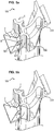
- the method comprises a first step 601 of providing a turbomachine rotor blade blank piece as described above and as shown figure 5a .
- the method comprises a second step of depositing a layer of anti-wear material 7 as described above in each bowl 5 formed, to obtain a heel 105 as shown figure 5b .
- the method comprises a third step 603 of machining the wall edges 501 and 502 of the bowl 5 protruding from the layer of anti-wear material 7 deposited, so as to obtain a blade machined as shown figure 5c .
- the method may include a fourth step 604 of grinding the surface of the anti-wear material layer 7 and the cup portion 5 after machining so as to smooth them.
Landscapes
- Engineering & Computer Science (AREA)
- Mechanical Engineering (AREA)
- General Engineering & Computer Science (AREA)
- Chemical & Material Sciences (AREA)
- Materials Engineering (AREA)
- Turbine Rotor Nozzle Sealing (AREA)
- Coating By Spraying Or Casting (AREA)
- Structures Of Non-Positive Displacement Pumps (AREA)
- Other Surface Treatments For Metallic Materials (AREA)
Claims (9)
- Rotorschaufel einer Turbomaschine, wobei die Schaufel an ihrem distalen Ende (103) einen Absatz (105) aufweist, Folgendes umfassend:- eine Plattform (2), die einen ersten Rand (201) an der Druckseite und einen zweiten Rand (202) an der Saugseite aufweist,- mindestens eine Dichtungslippe (3, 4), die einen ersten Endabschnitt (301) an der Druckseite und einen zweiten Endabschnitt (302) an der Saugseite aufweist, wobei die Dichtungslippe (3, 4) einen Lippenscheitel aufweist, der sich von der Plattform (2) zwischen dem ersten und zweiten Endabschnitt (301, 302) radial nach außen erstreckt, und der Absatz (105) für mindestens eine Lippe (3, 4) im Bereich mindestens eines der Ränder (201, 202) einen Abschnitt umfasst, der eine Mulde (5) bildet, die sich entlang des Endabschnitts (301, 302) der Lippe (3, 4) erstreckt, der dem Rand (201, 202) entspricht, wobei der Abschnitt, der eine Mulde (5) bildet, angepasst ist, um eine Abscheidung eines Verschleißschutzmaterials (7) aufzunehmen, und dadurch gekennzeichnet, dass sie eine Schicht an Verschleißschutzmaterial (7) umfasst, das durch Laden mit einer Legierung abgeschieden wird, die in jeder so gebildeten Mulde (5) aufgeschmolzen wird.
- Rotorschaufel nach Anspruch 1, dadurch gekennzeichnet, dass der Absatz (105) für mindestens eine Lippe (3, 4) im Bereich des ersten (201) beziehungsweise zweiten (202) Randes einen ersten, beziehungsweise zweiten Abschnitt umfasst, der eine Mulde (5) bildet, die sich entlang des ersten, beziehungsweise des zweiten Endabschnitts (301, 302) der Lippe (3, 4) erstreckt, wobei der erste, beziehungsweise der zweite Abschnitt, der eine Mulde (5) bildet, angepasst ist, um eine Abscheidung eines Verschleißschutzmaterials (7) aufzunehmen.
- Rotorschaufel nach einem der Ansprüche 1 oder 2, dadurch gekennzeichnet, dass jeder Abschnitt, der eine Mulde (5) bildet, zwei Wände (501, 502) umfasst, die sich beiderseits des entsprechenden Endabschnitts (301, 302) der Lippe (3, 4) erstrecken, wobei die Wände (501, 502), die die Seitenwände der Mulde (5) bilden und der Endabschnitt (301, 302) der Lippe (3, 4) den Boden der Mulde (5) bildet.
- Rotorschaufel nach einem der Ansprüche 1 bis 3, dadurch gekennzeichnet, dass sie eine stromaufwärtige Lippe (3) und eine stromabwärtige Lippe (4) umfasst.
- Rotorschaufel nach einem der Ansprüche 1 bis 4, dadurch gekennzeichnet, dass das Verschleißschutzmaterial in der Art von Stellit ist.
- Rotorschaufel einer Turbomaschine nach einem der Ansprüche 1 bis 5, dadurch gekennzeichnet, dass die Schaufel ein Schaufelrohteil vor Bearbeitung ist.
- Rotorschaufel einer Turbomaschine nach einem der Ansprüche 1 bis 5, dadurch gekennzeichnet, dass die Schaufel eine bearbeitete Schaufel ist.
- Verfahren zum Abscheiden eines Verschleißschutzmaterials auf einer Rotorschaufel einer Turbomaschine, umfassend die Schritte bestehend aus:- Bereitstellen eines Rotorschaufelrohteils einer Turbomaschine vor Bearbeitung, wobei das Teil an seinem distalen Ende (103) einen Absatz (105) aufweist, umfassend:- eine Plattform (2), die einen ersten Rand (201) an der Druckseite und einen zweiten Rand (202) an der Saugseite aufweist,- mindestens eine Dichtungslippe (3, 4), die einen ersten Endabschnitt (301) an der Druckseite und einen zweiten Endabschnitt (302) an der Saugseite aufweist, wobei die Lippe (3, 4) einen Lippenscheitel aufweist, der sich von der Plattform (2) zwischen dem ersten und zweiten Endabschnitt (301, 302) radial nach außen erstreckt, sodass der Absatz (105) für mindestens eine Lippe (3, 4) im Bereich mindestens eines der Ränder (201, 202) einen Abschnitt umfasst, der eine Mulde (5) bildet, die sich entlang des Endabschnitts (301, 302) der Lippe (3, 4) erstreckt, der dem Rand (201, 202) entspricht, wobei der Abschnitt, der eine Mulde (5) bildet, angepasst ist, um eine Abscheidung eines Verschleißschutzmaterials (7) aufzunehmen,- Abscheiden einer Schicht eines Verschleißschutzmaterials (7) durch Laden mit einer Legierung, die in jeder gebildeten Mulde (5) aufgeschmolzen wird, und- Bearbeiten der Seitenwände (501, 502) der Mulde (5), welche über die abgeschiedene Schicht eines Verschleißschutzmaterials (7) hinausragen.
- Verfahren nach Anspruch 8, dadurch gekennzeichnet, dass es weiter einen Schritt umfasst, der darin besteht, die Oberfläche der Schicht eines Verschleißschutzmaterials (7) und des bearbeiteten Abschnitts, der eine Mulde (5) bildet, abzuschleifen, um sie zu glätten.
Applications Claiming Priority (2)
| Application Number | Priority Date | Filing Date | Title |
|---|---|---|---|
| FR1350887A FR3001758B1 (fr) | 2013-02-01 | 2013-02-01 | Aube de rotor de turbomachine |
| PCT/FR2014/050129 WO2014118456A1 (fr) | 2013-02-01 | 2014-01-23 | Aube de rotor de turbomachine |
Publications (2)
| Publication Number | Publication Date |
|---|---|
| EP2951397A1 EP2951397A1 (de) | 2015-12-09 |
| EP2951397B1 true EP2951397B1 (de) | 2019-03-06 |
Family
ID=48083373
Family Applications (1)
| Application Number | Title | Priority Date | Filing Date |
|---|---|---|---|
| EP14705841.6A Active EP2951397B1 (de) | 2013-02-01 | 2014-01-23 | Turbomaschinenrotorschaufel |
Country Status (9)
| Country | Link |
|---|---|
| US (1) | US9963980B2 (de) |
| EP (1) | EP2951397B1 (de) |
| JP (2) | JP6887753B2 (de) |
| CN (1) | CN104968895B (de) |
| BR (1) | BR112015018390B8 (de) |
| CA (1) | CA2899675C (de) |
| FR (1) | FR3001758B1 (de) |
| RU (1) | RU2658451C2 (de) |
| WO (1) | WO2014118456A1 (de) |
Families Citing this family (19)
| Publication number | Priority date | Publication date | Assignee | Title |
|---|---|---|---|---|
| US9683446B2 (en) * | 2013-03-07 | 2017-06-20 | Rolls-Royce Energy Systems, Inc. | Gas turbine engine shrouded blade |
| WO2015061150A1 (en) * | 2013-10-21 | 2015-04-30 | United Technologies Corporation | Incident tolerant turbine vane gap flow discouragement |
| WO2017179711A1 (ja) | 2016-04-14 | 2017-10-19 | 三菱日立パワーシステムズ株式会社 | 蒸気タービン動翼、蒸気タービン、及び、蒸気タービン動翼の製造方法 |
| EP3269932A1 (de) * | 2016-07-13 | 2018-01-17 | MTU Aero Engines GmbH | Gasturbinenschaufel mit deckband |
| US10526899B2 (en) | 2017-02-14 | 2020-01-07 | General Electric Company | Turbine blade having a tip shroud |
| US10400610B2 (en) * | 2017-02-14 | 2019-09-03 | General Electric Company | Turbine blade having a tip shroud notch |
| FR3066780B1 (fr) * | 2017-05-24 | 2019-07-19 | Safran Aircraft Engines | Piece amovible anti-usure pour talon d'aube |
| DE102018201265A1 (de) | 2018-01-29 | 2019-08-01 | MTU Aero Engines AG | Deckbandsegment zur Anordnung an einer Schaufel einer Strömungsmaschine und Schaufel |
| FR3077600B1 (fr) * | 2018-02-08 | 2020-03-06 | Safran Aircraft Engines | Aube de turbomachine d'aeronef |
| FR3079847B1 (fr) | 2018-04-10 | 2023-11-10 | Safran Aircraft Engines | Procede de fabrication d'un element aubage metallique d'une turbomachine d'aeronef |
| DE112019003125B4 (de) * | 2018-06-19 | 2023-05-11 | Mitsubishi Heavy Industries, Ltd. | Turbinenrotorlaufschaufel, Turbomaschine und Kontaktflächenherstellungsverfahren |
| FR3084398B1 (fr) | 2018-07-24 | 2021-04-16 | Safran Aircraft Engines | Aube de turbine |
| FR3085419B1 (fr) | 2018-09-05 | 2020-08-07 | Safran Aircraft Engines | Aube mobile |
| FR3088671B1 (fr) * | 2018-11-16 | 2021-01-29 | Safran Aircraft Engines | Etancheite entre une roue mobile et un distributeur d'une turbomachine |
| FR3100271B1 (fr) * | 2019-09-04 | 2022-08-26 | Safran Aircraft Engines | Aube de turbomachine comportant un talon pourvu d’un becquet à plateforme déportée |
| FR3107079B1 (fr) * | 2020-02-07 | 2022-01-21 | Safran Aircraft Engines | Aube de turbomachine d’aeronef |
| EP3865665A1 (de) * | 2020-02-11 | 2021-08-18 | MTU Aero Engines AG | Schaufel für eine turbomaschine mit einem deckband |
| FR3119195B1 (fr) * | 2021-01-28 | 2023-04-14 | Safran Aircraft Engines | Mesure des déformations dynamiques d’une aube mobile |
| FR3125085B1 (fr) * | 2021-07-12 | 2025-02-28 | Safran Aircraft Engines | Aube de turbomachine |
Family Cites Families (16)
| Publication number | Priority date | Publication date | Assignee | Title |
|---|---|---|---|---|
| US4155152A (en) * | 1977-12-12 | 1979-05-22 | Matthew Bernardo | Method of restoring the shrouds of turbine blades |
| SU1403476A1 (ru) * | 1986-06-18 | 1995-09-10 | Институт проблем литья АН УССР | Способ наплавки заготовок |
| US4822248A (en) * | 1987-04-15 | 1989-04-18 | Metallurgical Industries, Inc. | Rebuilt shrouded turbine blade and method of rebuilding the same |
| FR2688803B1 (fr) * | 1992-03-23 | 1994-05-06 | European Gas Turbines Sa | Procede de revetement d'une encoche d'une piece en alliage de nickel par laser. |
| DE4439950C2 (de) * | 1994-11-09 | 2001-03-01 | Mtu Muenchen Gmbh | Metallisches Bauteil mit einer Verbundbeschichtung, Verwendung, sowie Verfahren zur Herstellung von metallischen Bauteilen |
| JPH1113402A (ja) * | 1997-06-23 | 1999-01-19 | Mitsubishi Heavy Ind Ltd | ガスタービン冷却翼チップシュラウド |
| JPH11336502A (ja) * | 1998-05-27 | 1999-12-07 | Mitsubishi Heavy Ind Ltd | 蒸気タービン動翼及びこの動翼を有する蒸気タービン |
| US20040124231A1 (en) * | 1999-06-29 | 2004-07-01 | Hasz Wayne Charles | Method for coating a substrate |
| JP4096301B2 (ja) * | 2002-10-09 | 2008-06-04 | 株式会社Ihi | 動翼及びそのコーティング方法 |
| CA2483528C (en) * | 2002-10-09 | 2015-07-21 | Ishikawajima-Harima Heavy Industries Co., Ltd. | Rotating member and method for coating the same |
| FR2860741B1 (fr) * | 2003-10-10 | 2007-04-13 | Snecma Moteurs | Procede de reparation de pieces metalliques notamment d'aubes de turbine de moteur a turbine a gaz |
| US7934315B2 (en) * | 2006-08-11 | 2011-05-03 | United Technologies Corporation | Method of repairing shrouded turbine blades with cracks in the vicinity of the outer shroud notch |
| US7771171B2 (en) * | 2006-12-14 | 2010-08-10 | General Electric Company | Systems for preventing wear on turbine blade tip shrouds |
| US20090202344A1 (en) * | 2008-02-13 | 2009-08-13 | General Electric Company | Rotating assembly for a turbomachine |
| FR2967714B1 (fr) * | 2010-11-22 | 2012-12-14 | Snecma | Aube mobile de turbomachine |
| FR2970999B1 (fr) * | 2011-02-02 | 2015-03-06 | Snecma | Aubes de turbomachine en cmc, roue mobile de turbomachine et turbomachine les comportant et procede pour leur fabrication |
-
2013
- 2013-02-01 FR FR1350887A patent/FR3001758B1/fr active Active
-
2014
- 2014-01-23 BR BR112015018390A patent/BR112015018390B8/pt active Search and Examination
- 2014-01-23 RU RU2015137085A patent/RU2658451C2/ru active
- 2014-01-23 EP EP14705841.6A patent/EP2951397B1/de active Active
- 2014-01-23 CN CN201480007121.7A patent/CN104968895B/zh active Active
- 2014-01-23 JP JP2015555767A patent/JP6887753B2/ja active Active
- 2014-01-23 WO PCT/FR2014/050129 patent/WO2014118456A1/fr not_active Ceased
- 2014-01-23 US US14/764,757 patent/US9963980B2/en active Active
- 2014-01-23 CA CA2899675A patent/CA2899675C/fr active Active
-
2019
- 2019-01-04 JP JP2019000263A patent/JP2019090417A/ja not_active Ceased
Non-Patent Citations (1)
| Title |
|---|
| None * |
Also Published As
| Publication number | Publication date |
|---|---|
| US9963980B2 (en) | 2018-05-08 |
| JP2016511354A (ja) | 2016-04-14 |
| RU2658451C2 (ru) | 2018-06-21 |
| CA2899675A1 (fr) | 2014-08-07 |
| EP2951397A1 (de) | 2015-12-09 |
| CN104968895A (zh) | 2015-10-07 |
| JP6887753B2 (ja) | 2021-06-16 |
| BR112015018390B8 (pt) | 2022-03-22 |
| CA2899675C (fr) | 2020-12-15 |
| RU2015137085A (ru) | 2017-03-06 |
| JP2019090417A (ja) | 2019-06-13 |
| FR3001758A1 (fr) | 2014-08-08 |
| FR3001758B1 (fr) | 2016-07-15 |
| BR112015018390B1 (pt) | 2022-01-25 |
| CN104968895B (zh) | 2017-04-12 |
| US20150369058A1 (en) | 2015-12-24 |
| WO2014118456A1 (fr) | 2014-08-07 |
| BR112015018390A2 (pt) | 2017-07-18 |
Similar Documents
| Publication | Publication Date | Title |
|---|---|---|
| CA2899675C (fr) | Aube de rotor avec depot de materiau anti-usure | |
| EP2805020B2 (de) | Turbomaschinenlaufschaufel und zugehörige Turbomaschine | |
| EP2643555B1 (de) | Laufschaufel einer Turbomaschine und zugehörige Turbomaschine | |
| EP2088286B1 (de) | Schaufel, zugehöriger beschaufelter Rotor und Strömungsmaschine | |
| EP3749838B2 (de) | Leitschaufel für ein flugzeugturbinentriebwerk | |
| EP1516690B1 (de) | Verfahren zur Herstellung oder Reparatur einer beschaufelten Rotorscheibe | |
| FR3066780B1 (fr) | Piece amovible anti-usure pour talon d'aube | |
| FR2977274A1 (fr) | Joint d'etancheite a labyrinthe pour turbine d'un moteur a turbine a gaz | |
| FR3079847A1 (fr) | Procede de fabrication d'un element aubage metallique d'une turbomachine d'aeronef | |
| EP3392464B1 (de) | Dichtungsringelement für turbine, das einen geneigten hohlraum in einem abriebmaterial umfasst | |
| WO2012056161A1 (fr) | Ensemble de disques de rotor pour une turbomachine | |
| EP4100624A1 (de) | Leitschaufel für ein flugzeugturbinentriebwerk | |
| FR2947016A1 (fr) | Compresseur centrifuge. | |
| CA2795458C (fr) | Masque amovible pour une plate-forme d'aube ou de secteur de distributeur de turbomachine | |
| EP4402347B1 (de) | Laufschaufel für eine turbine eines turbinentriebwerks mit einer neigung mit vorsprüngen zum radialen halten der schaufel | |
| EP3683450B1 (de) | Rotoranordnung einer strömungsmaschine | |
| FR3077601A1 (fr) | Aube de turbomachine d'aeronef | |
| FR3107720A1 (fr) | Aube de turbine, procédé de fabrication ou de reconditionnement du talon de ladite aube | |
| FR3072716A1 (fr) | Aube de rotor de turbomachine, turbomachine associee | |
| WO2020157405A1 (fr) | Secteur de stator de turbomachine a zones soumises a des contraintes élevées assouplies | |
| FR3164745A1 (fr) | Aube mobile de turbomachine comportant une structure sandwich | |
| FR3111158A1 (fr) | Pièce amovible anti-usure pour talon d’aube | |
| EP3991883A1 (de) | Verfahren zur herstellung einer leitschaufel für ein turbotriebwerk |
Legal Events
| Date | Code | Title | Description |
|---|---|---|---|
| PUAI | Public reference made under article 153(3) epc to a published international application that has entered the european phase |
Free format text: ORIGINAL CODE: 0009012 |
|
| 17P | Request for examination filed |
Effective date: 20150820 |
|
| AK | Designated contracting states |
Kind code of ref document: A1 Designated state(s): AL AT BE BG CH CY CZ DE DK EE ES FI FR GB GR HR HU IE IS IT LI LT LU LV MC MK MT NL NO PL PT RO RS SE SI SK SM TR |
|
| AX | Request for extension of the european patent |
Extension state: BA ME |
|
| DAX | Request for extension of the european patent (deleted) | ||
| REG | Reference to a national code |
Ref country code: DE Ref legal event code: R079 Ref document number: 602014042272 Country of ref document: DE Free format text: PREVIOUS MAIN CLASS: F01D0005220000 Ipc: F01D0011080000 |
|
| RAP1 | Party data changed (applicant data changed or rights of an application transferred) |
Owner name: SAFRAN AIRCRAFT ENGINES |
|
| GRAP | Despatch of communication of intention to grant a patent |
Free format text: ORIGINAL CODE: EPIDOSNIGR1 |
|
| STAA | Information on the status of an ep patent application or granted ep patent |
Free format text: STATUS: GRANT OF PATENT IS INTENDED |
|
| RIC1 | Information provided on ipc code assigned before grant |
Ipc: F01D 5/28 20060101ALI20180618BHEP Ipc: F01D 11/08 20060101AFI20180618BHEP Ipc: F01D 5/22 20060101ALI20180618BHEP |
|
| INTG | Intention to grant announced |
Effective date: 20180720 |
|
| GRAS | Grant fee paid |
Free format text: ORIGINAL CODE: EPIDOSNIGR3 |
|
| GRAJ | Information related to disapproval of communication of intention to grant by the applicant or resumption of examination proceedings by the epo deleted |
Free format text: ORIGINAL CODE: EPIDOSDIGR1 |
|
| GRAL | Information related to payment of fee for publishing/printing deleted |
Free format text: ORIGINAL CODE: EPIDOSDIGR3 |
|
| STAA | Information on the status of an ep patent application or granted ep patent |
Free format text: STATUS: REQUEST FOR EXAMINATION WAS MADE |
|
| GRAR | Information related to intention to grant a patent recorded |
Free format text: ORIGINAL CODE: EPIDOSNIGR71 |
|
| STAA | Information on the status of an ep patent application or granted ep patent |
Free format text: STATUS: GRANT OF PATENT IS INTENDED |
|
| INTC | Intention to grant announced (deleted) | ||
| INTG | Intention to grant announced |
Effective date: 20181218 |
|
| RIN1 | Information on inventor provided before grant (corrected) |
Inventor name: NEGRI, ARNAUD Inventor name: BENSALAH, SLIM Inventor name: TRAHOT, DENIS, GABRIEL Inventor name: GIMEL, ALEXANDRE Inventor name: BARD, ROMAIN Inventor name: LARDELLIER, THOMAS |
|
| GRAA | (expected) grant |
Free format text: ORIGINAL CODE: 0009210 |
|
| STAA | Information on the status of an ep patent application or granted ep patent |
Free format text: STATUS: THE PATENT HAS BEEN GRANTED |
|
| AK | Designated contracting states |
Kind code of ref document: B1 Designated state(s): AL AT BE BG CH CY CZ DE DK EE ES FI FR GB GR HR HU IE IS IT LI LT LU LV MC MK MT NL NO PL PT RO RS SE SI SK SM TR |
|
| REG | Reference to a national code |
Ref country code: GB Ref legal event code: FG4D Free format text: NOT ENGLISH |
|
| REG | Reference to a national code |
Ref country code: CH Ref legal event code: EP Ref country code: AT Ref legal event code: REF Ref document number: 1104821 Country of ref document: AT Kind code of ref document: T Effective date: 20190315 |
|
| REG | Reference to a national code |
Ref country code: DE Ref legal event code: R096 Ref document number: 602014042272 Country of ref document: DE |
|
| REG | Reference to a national code |
Ref country code: IE Ref legal event code: FG4D Free format text: LANGUAGE OF EP DOCUMENT: FRENCH |
|
| REG | Reference to a national code |
Ref country code: SE Ref legal event code: TRGR |
|
| REG | Reference to a national code |
Ref country code: NL Ref legal event code: MP Effective date: 20190306 |
|
| REG | Reference to a national code |
Ref country code: LT Ref legal event code: MG4D |
|
| PG25 | Lapsed in a contracting state [announced via postgrant information from national office to epo] |
Ref country code: LT Free format text: LAPSE BECAUSE OF FAILURE TO SUBMIT A TRANSLATION OF THE DESCRIPTION OR TO PAY THE FEE WITHIN THE PRESCRIBED TIME-LIMIT Effective date: 20190306 Ref country code: NO Free format text: LAPSE BECAUSE OF FAILURE TO SUBMIT A TRANSLATION OF THE DESCRIPTION OR TO PAY THE FEE WITHIN THE PRESCRIBED TIME-LIMIT Effective date: 20190606 Ref country code: FI Free format text: LAPSE BECAUSE OF FAILURE TO SUBMIT A TRANSLATION OF THE DESCRIPTION OR TO PAY THE FEE WITHIN THE PRESCRIBED TIME-LIMIT Effective date: 20190306 |
|
| PG25 | Lapsed in a contracting state [announced via postgrant information from national office to epo] |
Ref country code: LV Free format text: LAPSE BECAUSE OF FAILURE TO SUBMIT A TRANSLATION OF THE DESCRIPTION OR TO PAY THE FEE WITHIN THE PRESCRIBED TIME-LIMIT Effective date: 20190306 Ref country code: BG Free format text: LAPSE BECAUSE OF FAILURE TO SUBMIT A TRANSLATION OF THE DESCRIPTION OR TO PAY THE FEE WITHIN THE PRESCRIBED TIME-LIMIT Effective date: 20190606 Ref country code: RS Free format text: LAPSE BECAUSE OF FAILURE TO SUBMIT A TRANSLATION OF THE DESCRIPTION OR TO PAY THE FEE WITHIN THE PRESCRIBED TIME-LIMIT Effective date: 20190306 Ref country code: HR Free format text: LAPSE BECAUSE OF FAILURE TO SUBMIT A TRANSLATION OF THE DESCRIPTION OR TO PAY THE FEE WITHIN THE PRESCRIBED TIME-LIMIT Effective date: 20190306 Ref country code: GR Free format text: LAPSE BECAUSE OF FAILURE TO SUBMIT A TRANSLATION OF THE DESCRIPTION OR TO PAY THE FEE WITHIN THE PRESCRIBED TIME-LIMIT Effective date: 20190607 Ref country code: NL Free format text: LAPSE BECAUSE OF FAILURE TO SUBMIT A TRANSLATION OF THE DESCRIPTION OR TO PAY THE FEE WITHIN THE PRESCRIBED TIME-LIMIT Effective date: 20190306 |
|
| REG | Reference to a national code |
Ref country code: AT Ref legal event code: MK05 Ref document number: 1104821 Country of ref document: AT Kind code of ref document: T Effective date: 20190306 |
|
| PG25 | Lapsed in a contracting state [announced via postgrant information from national office to epo] |
Ref country code: PT Free format text: LAPSE BECAUSE OF FAILURE TO SUBMIT A TRANSLATION OF THE DESCRIPTION OR TO PAY THE FEE WITHIN THE PRESCRIBED TIME-LIMIT Effective date: 20190706 Ref country code: AL Free format text: LAPSE BECAUSE OF FAILURE TO SUBMIT A TRANSLATION OF THE DESCRIPTION OR TO PAY THE FEE WITHIN THE PRESCRIBED TIME-LIMIT Effective date: 20190306 Ref country code: ES Free format text: LAPSE BECAUSE OF FAILURE TO SUBMIT A TRANSLATION OF THE DESCRIPTION OR TO PAY THE FEE WITHIN THE PRESCRIBED TIME-LIMIT Effective date: 20190306 Ref country code: SK Free format text: LAPSE BECAUSE OF FAILURE TO SUBMIT A TRANSLATION OF THE DESCRIPTION OR TO PAY THE FEE WITHIN THE PRESCRIBED TIME-LIMIT Effective date: 20190306 Ref country code: CZ Free format text: LAPSE BECAUSE OF FAILURE TO SUBMIT A TRANSLATION OF THE DESCRIPTION OR TO PAY THE FEE WITHIN THE PRESCRIBED TIME-LIMIT Effective date: 20190306 Ref country code: RO Free format text: LAPSE BECAUSE OF FAILURE TO SUBMIT A TRANSLATION OF THE DESCRIPTION OR TO PAY THE FEE WITHIN THE PRESCRIBED TIME-LIMIT Effective date: 20190306 Ref country code: EE Free format text: LAPSE BECAUSE OF FAILURE TO SUBMIT A TRANSLATION OF THE DESCRIPTION OR TO PAY THE FEE WITHIN THE PRESCRIBED TIME-LIMIT Effective date: 20190306 |
|
| PG25 | Lapsed in a contracting state [announced via postgrant information from national office to epo] |
Ref country code: PL Free format text: LAPSE BECAUSE OF FAILURE TO SUBMIT A TRANSLATION OF THE DESCRIPTION OR TO PAY THE FEE WITHIN THE PRESCRIBED TIME-LIMIT Effective date: 20190306 Ref country code: SM Free format text: LAPSE BECAUSE OF FAILURE TO SUBMIT A TRANSLATION OF THE DESCRIPTION OR TO PAY THE FEE WITHIN THE PRESCRIBED TIME-LIMIT Effective date: 20190306 |
|
| REG | Reference to a national code |
Ref country code: DE Ref legal event code: R097 Ref document number: 602014042272 Country of ref document: DE |
|
| PG25 | Lapsed in a contracting state [announced via postgrant information from national office to epo] |
Ref country code: IS Free format text: LAPSE BECAUSE OF FAILURE TO SUBMIT A TRANSLATION OF THE DESCRIPTION OR TO PAY THE FEE WITHIN THE PRESCRIBED TIME-LIMIT Effective date: 20190706 Ref country code: AT Free format text: LAPSE BECAUSE OF FAILURE TO SUBMIT A TRANSLATION OF THE DESCRIPTION OR TO PAY THE FEE WITHIN THE PRESCRIBED TIME-LIMIT Effective date: 20190306 |
|
| PLBE | No opposition filed within time limit |
Free format text: ORIGINAL CODE: 0009261 |
|
| STAA | Information on the status of an ep patent application or granted ep patent |
Free format text: STATUS: NO OPPOSITION FILED WITHIN TIME LIMIT |
|
| PG25 | Lapsed in a contracting state [announced via postgrant information from national office to epo] |
Ref country code: DK Free format text: LAPSE BECAUSE OF FAILURE TO SUBMIT A TRANSLATION OF THE DESCRIPTION OR TO PAY THE FEE WITHIN THE PRESCRIBED TIME-LIMIT Effective date: 20190306 |
|
| 26N | No opposition filed |
Effective date: 20191209 |
|
| PG25 | Lapsed in a contracting state [announced via postgrant information from national office to epo] |
Ref country code: SI Free format text: LAPSE BECAUSE OF FAILURE TO SUBMIT A TRANSLATION OF THE DESCRIPTION OR TO PAY THE FEE WITHIN THE PRESCRIBED TIME-LIMIT Effective date: 20190306 |
|
| PG25 | Lapsed in a contracting state [announced via postgrant information from national office to epo] |
Ref country code: TR Free format text: LAPSE BECAUSE OF FAILURE TO SUBMIT A TRANSLATION OF THE DESCRIPTION OR TO PAY THE FEE WITHIN THE PRESCRIBED TIME-LIMIT Effective date: 20190306 |
|
| PG25 | Lapsed in a contracting state [announced via postgrant information from national office to epo] |
Ref country code: MC Free format text: LAPSE BECAUSE OF FAILURE TO SUBMIT A TRANSLATION OF THE DESCRIPTION OR TO PAY THE FEE WITHIN THE PRESCRIBED TIME-LIMIT Effective date: 20190306 |
|
| REG | Reference to a national code |
Ref country code: CH Ref legal event code: PL |
|
| REG | Reference to a national code |
Ref country code: BE Ref legal event code: MM Effective date: 20200131 |
|
| PG25 | Lapsed in a contracting state [announced via postgrant information from national office to epo] |
Ref country code: LU Free format text: LAPSE BECAUSE OF NON-PAYMENT OF DUE FEES Effective date: 20200123 |
|
| PG25 | Lapsed in a contracting state [announced via postgrant information from national office to epo] |
Ref country code: CH Free format text: LAPSE BECAUSE OF NON-PAYMENT OF DUE FEES Effective date: 20200131 Ref country code: LI Free format text: LAPSE BECAUSE OF NON-PAYMENT OF DUE FEES Effective date: 20200131 Ref country code: BE Free format text: LAPSE BECAUSE OF NON-PAYMENT OF DUE FEES Effective date: 20200131 |
|
| PG25 | Lapsed in a contracting state [announced via postgrant information from national office to epo] |
Ref country code: IE Free format text: LAPSE BECAUSE OF NON-PAYMENT OF DUE FEES Effective date: 20200123 |
|
| PG25 | Lapsed in a contracting state [announced via postgrant information from national office to epo] |
Ref country code: MT Free format text: LAPSE BECAUSE OF FAILURE TO SUBMIT A TRANSLATION OF THE DESCRIPTION OR TO PAY THE FEE WITHIN THE PRESCRIBED TIME-LIMIT Effective date: 20190306 Ref country code: CY Free format text: LAPSE BECAUSE OF FAILURE TO SUBMIT A TRANSLATION OF THE DESCRIPTION OR TO PAY THE FEE WITHIN THE PRESCRIBED TIME-LIMIT Effective date: 20190306 |
|
| PG25 | Lapsed in a contracting state [announced via postgrant information from national office to epo] |
Ref country code: MK Free format text: LAPSE BECAUSE OF FAILURE TO SUBMIT A TRANSLATION OF THE DESCRIPTION OR TO PAY THE FEE WITHIN THE PRESCRIBED TIME-LIMIT Effective date: 20190306 |
|
| PGFP | Annual fee paid to national office [announced via postgrant information from national office to epo] |
Ref country code: SE Payment date: 20260121 Year of fee payment: 13 |
|
| PGFP | Annual fee paid to national office [announced via postgrant information from national office to epo] |
Ref country code: GB Payment date: 20260122 Year of fee payment: 13 |
|
| PGFP | Annual fee paid to national office [announced via postgrant information from national office to epo] |
Ref country code: DE Payment date: 20260120 Year of fee payment: 13 |
|
| PGFP | Annual fee paid to national office [announced via postgrant information from national office to epo] |
Ref country code: IT Payment date: 20260130 Year of fee payment: 13 |
|
| PGFP | Annual fee paid to national office [announced via postgrant information from national office to epo] |
Ref country code: FR Payment date: 20260128 Year of fee payment: 13 |