EP2951452B1 - Non intrusive agitation system - Google Patents
Non intrusive agitation system Download PDFInfo
- Publication number
- EP2951452B1 EP2951452B1 EP13704896.3A EP13704896A EP2951452B1 EP 2951452 B1 EP2951452 B1 EP 2951452B1 EP 13704896 A EP13704896 A EP 13704896A EP 2951452 B1 EP2951452 B1 EP 2951452B1
- Authority
- EP
- European Patent Office
- Prior art keywords
- container
- protrusions
- inter
- related product
- flexible element
- Prior art date
- Legal status (The legal status is an assumption and is not a legal conclusion. Google has not performed a legal analysis and makes no representation as to the accuracy of the status listed.)
- Not-in-force
Links
Images


Classifications
-
- B—PERFORMING OPERATIONS; TRANSPORTING
- B01—PHYSICAL OR CHEMICAL PROCESSES OR APPARATUS IN GENERAL
- B01F—MIXING, e.g. DISSOLVING, EMULSIFYING OR DISPERSING
- B01F27/00—Mixers with rotary stirring devices in fixed receptacles; Kneaders
- B01F27/21—Mixers with rotary stirring devices in fixed receptacles; Kneaders characterised by their rotating shafts
- B01F27/213—Mixers with rotary stirring devices in fixed receptacles; Kneaders characterised by their rotating shafts characterised by the connection with the drive
-
- B—PERFORMING OPERATIONS; TRANSPORTING
- B01—PHYSICAL OR CHEMICAL PROCESSES OR APPARATUS IN GENERAL
- B01F—MIXING, e.g. DISSOLVING, EMULSIFYING OR DISPERSING
- B01F27/00—Mixers with rotary stirring devices in fixed receptacles; Kneaders
- B01F27/60—Mixers with rotary stirring devices in fixed receptacles; Kneaders with stirrers rotating about a horizontal or inclined axis
- B01F27/72—Mixers with rotary stirring devices in fixed receptacles; Kneaders with stirrers rotating about a horizontal or inclined axis with helices or sections of helices
- B01F27/724—Mixers with rotary stirring devices in fixed receptacles; Kneaders with stirrers rotating about a horizontal or inclined axis with helices or sections of helices with a single helix closely surrounded by a casing
-
- B—PERFORMING OPERATIONS; TRANSPORTING
- B01—PHYSICAL OR CHEMICAL PROCESSES OR APPARATUS IN GENERAL
- B01F—MIXING, e.g. DISSOLVING, EMULSIFYING OR DISPERSING
- B01F27/00—Mixers with rotary stirring devices in fixed receptacles; Kneaders
- B01F27/80—Mixers with rotary stirring devices in fixed receptacles; Kneaders with stirrers rotating about a substantially vertical axis
- B01F27/88—Mixers with rotary stirring devices in fixed receptacles; Kneaders with stirrers rotating about a substantially vertical axis with a separate receptacle-stirrer unit that is adapted to be coupled to a drive mechanism
-
- B—PERFORMING OPERATIONS; TRANSPORTING
- B01—PHYSICAL OR CHEMICAL PROCESSES OR APPARATUS IN GENERAL
- B01F—MIXING, e.g. DISSOLVING, EMULSIFYING OR DISPERSING
- B01F31/00—Mixers with shaking, oscillating, or vibrating mechanisms
- B01F31/30—Mixers with shaking, oscillating, or vibrating mechanisms comprising a receptacle to only a part of which the shaking, oscillating, or vibrating movement is imparted
- B01F31/31—Mixers with shaking, oscillating, or vibrating mechanisms comprising a receptacle to only a part of which the shaking, oscillating, or vibrating movement is imparted using receptacles with deformable parts, e.g. membranes, to which a motion is imparted
-
- B—PERFORMING OPERATIONS; TRANSPORTING
- B01—PHYSICAL OR CHEMICAL PROCESSES OR APPARATUS IN GENERAL
- B01F—MIXING, e.g. DISSOLVING, EMULSIFYING OR DISPERSING
- B01F35/00—Accessories for mixers; Auxiliary operations or auxiliary devices; Parts or details of general application
- B01F35/20—Measuring; Control or regulation
- B01F35/22—Control or regulation
- B01F35/221—Control or regulation of operational parameters, e.g. level of material in the mixer, temperature or pressure
- B01F35/2215—Temperature
-
- B—PERFORMING OPERATIONS; TRANSPORTING
- B01—PHYSICAL OR CHEMICAL PROCESSES OR APPARATUS IN GENERAL
- B01F—MIXING, e.g. DISSOLVING, EMULSIFYING OR DISPERSING
- B01F35/00—Accessories for mixers; Auxiliary operations or auxiliary devices; Parts or details of general application
- B01F35/30—Driving arrangements; Transmissions; Couplings; Brakes
- B01F35/32—Driving arrangements
- B01F35/32005—Type of drive
-
- B—PERFORMING OPERATIONS; TRANSPORTING
- B01—PHYSICAL OR CHEMICAL PROCESSES OR APPARATUS IN GENERAL
- B01F—MIXING, e.g. DISSOLVING, EMULSIFYING OR DISPERSING
- B01F35/00—Accessories for mixers; Auxiliary operations or auxiliary devices; Parts or details of general application
- B01F35/50—Mixing receptacles
- B01F35/513—Flexible receptacles, e.g. bags supported by rigid containers
-
- C—CHEMISTRY; METALLURGY
- C12—BIOCHEMISTRY; BEER; SPIRITS; WINE; VINEGAR; MICROBIOLOGY; ENZYMOLOGY; MUTATION OR GENETIC ENGINEERING
- C12M—APPARATUS FOR ENZYMOLOGY OR MICROBIOLOGY; APPARATUS FOR CULTURING MICROORGANISMS FOR PRODUCING BIOMASS, FOR GROWING CELLS OR FOR OBTAINING FERMENTATION OR METABOLIC PRODUCTS, i.e. BIOREACTORS OR FERMENTERS
- C12M23/00—Constructional details, e.g. recesses, hinges
- C12M23/26—Constructional details, e.g. recesses, hinges flexible
-
- C—CHEMISTRY; METALLURGY
- C12—BIOCHEMISTRY; BEER; SPIRITS; WINE; VINEGAR; MICROBIOLOGY; ENZYMOLOGY; MUTATION OR GENETIC ENGINEERING
- C12M—APPARATUS FOR ENZYMOLOGY OR MICROBIOLOGY; APPARATUS FOR CULTURING MICROORGANISMS FOR PRODUCING BIOMASS, FOR GROWING CELLS OR FOR OBTAINING FERMENTATION OR METABOLIC PRODUCTS, i.e. BIOREACTORS OR FERMENTERS
- C12M27/00—Means for mixing, agitating or circulating fluids in the vessel
- C12M27/02—Stirrer or mobile mixing elements
- C12M27/06—Stirrer or mobile mixing elements with horizontal or inclined stirrer shaft or axis
-
- B—PERFORMING OPERATIONS; TRANSPORTING
- B01—PHYSICAL OR CHEMICAL PROCESSES OR APPARATUS IN GENERAL
- B01F—MIXING, e.g. DISSOLVING, EMULSIFYING OR DISPERSING
- B01F2101/00—Mixing characterised by the nature of the mixed materials or by the application field
- B01F2101/44—Mixing of ingredients for microbiology, enzymology, in vitro culture or genetic manipulation
-
- B—PERFORMING OPERATIONS; TRANSPORTING
- B01—PHYSICAL OR CHEMICAL PROCESSES OR APPARATUS IN GENERAL
- B01F—MIXING, e.g. DISSOLVING, EMULSIFYING OR DISPERSING
- B01F31/00—Mixers with shaking, oscillating, or vibrating mechanisms
- B01F31/29—Mixing by periodically deforming flexible tubular members through which the material is flowing
-
- B—PERFORMING OPERATIONS; TRANSPORTING
- B01—PHYSICAL OR CHEMICAL PROCESSES OR APPARATUS IN GENERAL
- B01F—MIXING, e.g. DISSOLVING, EMULSIFYING OR DISPERSING
- B01F35/00—Accessories for mixers; Auxiliary operations or auxiliary devices; Parts or details of general application
- B01F35/30—Driving arrangements; Transmissions; Couplings; Brakes
- B01F35/31—Couplings
Definitions
- the invention provides means for the controlled, contained and non-intrusive agitation of the contents of a closed container, without introducing any piece or particle inside said container.
- Some processes such as cell culture, need that a fluid inside a container is agitated. This step can be achieved in many ways, but achieving it by introducing some moving external piece inside the container has many disadvantages.
- Patent US 6,190,913 describes a rocking platform that applies a rocking movement to a bag partially filled with a cell suspension, thus achieving simultaneous agitation of the suspension and aeration of the culture due to gas exchange between the liquid phase and the gas phase on top.
- Patent US 3,941,661 describes adherent cells growing on the inner wall of a cylindrical bottle which are periodically submerged in a liquid culture medium contained in the bottle as the horizontal bottle rotates about its longitudinal axis.
- Patent US 5,816,702 proposes the use of a vane mounted in the interior of a drum thus increasing the mixing of the fluid contents of the vessel.
- Patent US 4,732,487 describes the application of an oscillating movement to the wall of a vessel such that this movement transfers the oscillating movement to a mixing plate secured to the inner side of the oscillating wall.
- the plate oscillates at larger amplitude than that applied to the wall, thus producing a mixing effect of liquids contained in the vessel.
- Patent US 4,685,811 describes the use of a fluidic diode comprising a perforated plate contained in a vessel in such a way that the different path followed by the liquid when flowing in different directions creates a mixing effect.
- Patent US 7,083,323 proposes the movement from one compartment to another of the liquid content of a multi-compartment flexible vessel. By compressing the walls of the different compartments, the liquid is forced to pass through small passages that increase flow speed and create a mixing effect.
- Patent US 5,443,985 proposes the culture of cells in suspension using a long inclined culture chamber where gas bubbles introduced at the bottom of the chamber progressed to the top of the chamber along the interphase between the cell suspension and the chamber wall, thus gently agitating the cell suspension contained in the chamber and simultaneously providing gas exchange.
- Magnetic coupling is commonly used in open systems to agitate the liquid contents of vessels.
- an open vessel containing the liquid to be agitated and a magnet is placed on top of a surface that covers a rotating magnetic field. Examples of this technique can be found in patent US 4,209,259 or in patent US 3,647,632 .
- the invention suggests an improved solution to the previous drawbacks.
- the invention relates to a first interrelated product according to claim 1, a second interrelated product according to claim 8 and a system according to claim 11.
- Preferred embodiments of the invention are defined in dependent claims.
- the invention provides a first inter-related product for non intrusive agitation of a fluid, suitable for cell culture, in accordance with the features of claim 1.
- the main movable stirring means are mechanically coupled to secondary stirring means located within the container wherein the movement of the secondary stirring means is driven by the movement of the main movable stirring means.
- the main movable stirring means and the secondary stirring means are two coupled gear wheel shaped elements, fitted to the walls of the container so that when rotating, the first inter-related product works as an impeller, pumping fluid from a fluid supply to a fluid drain.
- the surface of the main movable stirring means is modified by means of functionalising said surface or coating said surface with catalysts, chemical reagents, cells, polymers or crystals.
- the first inter-related product further comprises inlet and outlet means to supply and extract at least one fluid from the container.
- the container comprises a guiding housing and the main movable stirring means comprise at least one corresponding guided projection adapted to be housed in the guiding housing of the container allowing a guided movement of the main movable stirring means in respect of the container.
- the container comprises thermostating means adapted to keep a constant temperature within the container.
- cylindrical must be interpreted in its broadest sense, i.e., a surface generated by a closed curve or generatrix extending according to a directrix, for instance a longitudinal axis or a curve of low curvature.
- examples of cylindrical walls are those offered by tubular bodies having a circular or polygonal section.
- the plate comprises a spiral section and extends along the longitudinal axis of the container between a first end and a second end.
- the spiral section is transversal to the longitudinal axis of the container.
- the spiral section comprised in the plate is closed in both ends by two lateral walls, at least one of the walls having a drain hole in communication with the internal cavity of the container for allowing the outlet of a fluid from the inner part of the plate comprising the spiral section such that, in an operative mode, the plate with the spiral section is adapted to transport by rotation the fluid of the container to the inner part of the plate comprising the spiral section, and the drain hole is adapted to return the fluid from the inner part of the plate to the outer part of the plate back to be in contact with the inner walls of the container.
- the main movable stirring means comprise a set of nested cylinders such that:
- each cylinder is by means of outlets located in alternating ends in such a way that the flow alternates the direction when flowing in each cylinder.
- first protrusions are cylindrical first protrusions substantially parallel to the longitudinal axis of the container and linked with the driven structure by connecting elements.
- the main movable stirring means comprise also a plate comprising a helical portion or helical blades with the longitudinal axis of the helix essentially parallel to the longitudinal axis of the container and adapted to raise the fluid contained in the container.
- the container comprises a second container to store said fluid and the second container is integral with the main movable stirring means.
- the invention provides a second inter-related product in accordance with the features of claim 8.
- the second inter-related product is further adapted to move in a lineal trajectory or in a circular trajectory or in a combination of both.
- the second inter-related product adapted to act over a first inter-related product according to the first inventive aspect further comprises a plurality of second protrusions, and the impulsion means and the main movable stirring means are arranged so that the second protrusions are suitable for housing the first protrusions by the interposition of the first flexible element.
- the second protrusions are adapted to house the first protrusions in more than one housing position.
- the invention provides a system comprising a combination of a first inter-related product according to the first inventive aspect and a second inter-related product according to the second inventive aspect.
- the first inter-related product is located in a first chamber and the second inter-related product is located in a second chamber, said chambers separated by a wall, the wall further comprising a second flexible element located between the impulsion means and the first flexible element of the container, preferably a membrane, to provide a separation between the environment surrounding the first inter-related product and the environment surrounding the second inter-related product.
- FIG 1 shows a cell culture system (1) according to the invention.
- This system (1) comprises a bottle (10) and a machine (20).
- both devices are placed on opposite sides of a perforated wall (8) that separates the chambers where the bottle (10) and the machine (20) are placed.
- An isolating membrane (5) separates the bottle (10) from the machine (20) effectively segregating both sides of the wall (8) and preventing any contact between the bottle (10) and the machine (20).
- each isolated chamber is the size of a room.
- the wall (8) and the isolating membrane (5) separate two different rooms, thus fully isolating the machine (20) and personnel working on the machine (20) from the bottle (10) and personnel working on the bottle (10).
- the working space where cells are manipulated is fully isolated from other working spaces with high contamination risk.
- the bottle (10) is a container (11) comprising the following elements:
- the container membrane (14) closes the container (11) hermetically, so that the container can stay watertight and sterile indefinitely, unless it is opened or broken by other reasons. At the same time, it allows the elements inside the container (11) be affected by the elements outside the container (11) which interact with said container membrane (14).
- the plate (151) is a thin sheet, or a set of them, arranged in many different ways in different embodiments, as far as it stirs the fluid (4) contained inside the container (11).
- the plate (151) is a set of helical blades; in another embodiment, the plate (151) is a rolled sheet; in another embodiment, the plate (151) is a set of mill blades; in another embodiment the plate (151) is a set of radial curved blades.
- the guiding housing (17) of the container (11) is suitable to house a corresponding guided projection (18) comprised in the main movable stirring means (15), allowing a guided movement of the main movable stirring means (15) in respect of the container (11).
- the driven structure (152) is a piece which supports the plate (151) and comprises first protrusions (16).
- these first protrusions (16) allow the interaction of the bottle (10) with the rest of the elements of the system (1), as it will be described below.
- these first protrusions (16) are idle spherical protrusions.
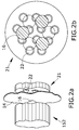
- These impulsion means (21) comprise second protrusions (22).
- these second protrusions (22) are arranged in groups of three semispherical protrusions.
- the second protrusions (22) are arranged so that each group of three second protrusions (22) house one first protrusion (16).
- the rotating movement of the impulsion means (21) in the machine (20) makes the second protrusions (22) follow a circular trajectory.
- This circular trajectory is conveyed to the first protrusions (16) of the driven structure (152) via the mechanical coupling between them. This coupling is made possible by the deformations of the isolating membrane (5) and the container membrane (14).
- holding the bottle (10) by one end leaves the bottle overhanging and allows for easy manipulation and placement of tubing and connections.
- both guiding housing (17) and guided projection (18) are concentric to the circular trajectory followed by the impulsion means (21).
- the rotating movement of the driven structure (152) is carried out when the impulsion means (21) of the machine (20) is performing a rotating movement.
- the rotating movement of the impulsion means (21) of the machine (20) makes the plate (151) rotate in the counter clockwise direction thus introducing the fluid (4) inside the plate (151).
- FIG 3a and FIG 3b show a detail of the interaction between the plate (151), the fluid (4) and the container (11).
- the gravity makes the fluid (4) accumulate at the bottom of the container (11) and in different zones of the plate (151).
- the fluid (4) accumulates at the bottom of the container (11) and at the lower portion of each of the turns of the spiral section of the plate (151), thus allowing for the soaking of the whole spiral plate (151) as it rotates.
- FIG 3b shows a side sectional view of the container (11), with the spiral plate (151) and the fluid (4).
- the plate (151) is closed in both ends by two lateral walls (155).
- one of the walls (155) has a drain hole (153) in communication with the internal cavity of the container (11) to allow outlet of the fluid (4) from the inner part of the spiral sheet such that, in an operative mode, the plate (151) is adapted to transport by rotation the fluid of the container to the inner part of the plate (151), and the drain hole (153) is adapted to return the fluid (4) from the inner part of the plate (151) back to be in contact with the inner walls of the container (11).
- this way of conveying the fluid (4) allows for the plate (151) to be in alternating contact both with the fluid (4) and with the gas phase, since the outer end of the open spiral section of the plate (151) does not remain continuously submerged in said fluid (4).
- the rotating direction of the impulsion means (21) is reversible.
- the straight rotating direction of the impulsion means (21) leads to the emptying of the spiral through the drain hole (153) which is in communication with the internal cavity of the container (11).
- the inverse rotating direction of the impulsion means (21) leads to the emptying of the spiral through the outer loop of the spiral sheet.
- the rotation speed and direction of the impulsion means (21) is controlled by a programmable control loop that responds to the value of the parameters measured by probes (41, 42, 33, 37, 51, 52) located both in the container (11) and in the impulsion means (21).
- Operation of the system (1) is initiated by fastening the bottle (10) with the fastening means (7) in one of the available positions of the first protrusions (16) and the second protrusions (22).
- thermostating element (13) is an annular cylindrical chamber surrounding the cylindrical wall of the container (11) where a thermostating fluid at controlled temperature circulates continuously.
- the thermostating fluid leaves the thermostating element (13) through the thermostating fluid outlet (32).
- a temperature probe (41) indicates the actual temperature within the container (11) so that flow speed or temperature of the thermostating fluid can be modified in order to reach a set value.
- this thermostating process is automated by connecting the temperature probe (41) to a sensing element and a control loop with integrated pumps of the type found in the state of art.
- the thermostating element (13) is replaced with a surrounding heating wire uniformly distributed on the surface of the device.
- the system is placed within a controlled environment where gaseous carbon dioxide is present, so the gas can diffuse into the container (11) through a filtering membrane in the filter lid (34).
- a harvesting fluid such as a trypsin solution
- the harvested cell suspension is recovered through fluid drain (43).
- a washing step with a mild buffered solution is performed before harvesting and/or cell suspension collection happens through the filter lid (34) opening.
- rotation speed and direction throughout the entire process is programmably controlled.
- Further probes (51, 52) on the machine (20) are available for temperature control and impulsion means (21) speed control.
- the wall (8) is part of a cover that surrounds the machine (20).
- programming, controlling and/or monitoring are carried out from remote locations.
- the container (11) is a thermostated chamber comprising a roller bottle (3) inside, and the machine (20) is the same as in the embodiment of FIG 1 .
- the machine (20) thus, comprises impulsion means (21), which, in turn, comprise second protrusions (22).
- these second protrusions (22) are arranged in groups of three idle spherical protrusions and the thermostating element (13) is a heated wire.
- the second protrusions (22) are arranged in the same way as in the embodiment of FIG 1 .
- the roller bottle (3) of this embodiment comprises the fluid (4) inside.
- the roller bottle (3) also comprises the driven structure (152) and the driven structure (152) comprises a rotatable annulus (154) and the first protrusions (16), which interact with the second protrusions (22).
- the roller bottle (3) comprises securing means, such as clamps (6).
- the roller bottle (3) is secured by a set of clamps (6), allowing for easy removal and replacement.
- the container membrane (14) segregates the machine (20) from the inner part of the container (11) where the roller bottle (3) is located.
- this second preferred embodiment is used in cell culture processes, removal and replacing of the roller bottle (3) can be performed manually during operation, since rotating speed used in this processes is usually slower than 5 rpm.
- the machine (20) When the machine (20) operates, it sets the driving structure (152) in motion and, as described for the first preferred embodiment, the rotating movement will be conveyed to the roller bottle (3), which is horizontally placed.
- the culture media continuously soaks the inner side of the cylindrical wall of the roller bottle (3) where adherent cells are attached, thus feeding the cells.
- several systems (1) are arranged in the same wall (8) with different container membranes (14) forming a multi-chamber machine.
- several roller bottles (3) are installed within a large single container (11), advantageously multiplying the throughput of the overall system.
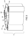
- FIG 5 A further described embodiment not forming part of the claimed invention is partially represented in FIG 5 .
- three cylindrical second protrusions (22) are arranged parallel to the longitudinal axis of the cylindrical container membrane (14). Since the distance from each second protrusion (22) to the center of the container membrane (14) is shorter than the radius of the container membrane (14), a deformation of the container membrane (14) is created by each of the second protrusions (22).
- first protrusions (16) are, in turn, three cylindrical first protrusions, parallel to the cylindrical second protrusions (22). They are all linked with the driven structure (152), by a series of connecting elements (19) that join the center element with each cylindrical first protrusion (16).
- the second protrusions (22) When the second protrusions (22) rotate, they follow a circular trajectory concentric to the container (11) axis while simultaneously rolling on the container membrane (14) and thus rotating about their respective longitudinal axis.
- the combined effect of the moving second protrusions (22) and the pressure within the container (11) due to the fluid contained in the container (11) makes the deformations in the flexible container membrane (14) follow a circular trajectory corresponding to the trajectory followed by the second protrusions (22).
- the driven structure (152) When the resulting deformations created in the container membrane (14) encounter the first protrusions (16) the driven structure (152) is forced to rotate following a trajectory concentric to the container (11) axis, therefore making the connecting elements (19) linking the cylindrical first protrusions (16) to the driven structure (152) agitate the fluid (4) within the container (11).
- the first inter-related product disclosed in the present invention can be fully built in materials, such as plastic, adequate for radiation sterilization, such as gamma radiation.
- these embodiments offer a major improvement of watertightness, containment and steriliy of the container (11) contents, without affecting the internal working of the main movable stirring means (15). This is so even though, these main movable stirring means (15) perform a better working, being even more suitable than the current devices for several biotechnological applications, such as:
Landscapes
- Chemical & Material Sciences (AREA)
- Chemical Kinetics & Catalysis (AREA)
- Health & Medical Sciences (AREA)
- Wood Science & Technology (AREA)
- Life Sciences & Earth Sciences (AREA)
- Engineering & Computer Science (AREA)
- Bioinformatics & Cheminformatics (AREA)
- Organic Chemistry (AREA)
- Zoology (AREA)
- Sustainable Development (AREA)
- Microbiology (AREA)
- Biotechnology (AREA)
- Biochemistry (AREA)
- General Engineering & Computer Science (AREA)
- General Health & Medical Sciences (AREA)
- Genetics & Genomics (AREA)
- Biomedical Technology (AREA)
- Clinical Laboratory Science (AREA)
- Apparatus Associated With Microorganisms And Enzymes (AREA)
Priority Applications (1)
| Application Number | Priority Date | Filing Date | Title |
|---|---|---|---|
| PL13704896T PL2951452T3 (pl) | 2013-02-01 | 2013-02-01 | Układ mieszania nieintruzywnego |
Applications Claiming Priority (1)
| Application Number | Priority Date | Filing Date | Title |
|---|---|---|---|
| PCT/EP2013/052039 WO2014117859A1 (en) | 2013-02-01 | 2013-02-01 | Non intrusive agitation system |
Publications (2)
| Publication Number | Publication Date |
|---|---|
| EP2951452A1 EP2951452A1 (en) | 2015-12-09 |
| EP2951452B1 true EP2951452B1 (en) | 2016-08-31 |
Family
ID=47739211
Family Applications (1)
| Application Number | Title | Priority Date | Filing Date |
|---|---|---|---|
| EP13704896.3A Not-in-force EP2951452B1 (en) | 2013-02-01 | 2013-02-01 | Non intrusive agitation system |
Country Status (7)
| Country | Link |
|---|---|
| US (1) | US10427121B2 (pl) |
| EP (1) | EP2951452B1 (pl) |
| DK (1) | DK2951452T3 (pl) |
| ES (1) | ES2601227T3 (pl) |
| PL (1) | PL2951452T3 (pl) |
| PT (1) | PT2951452T (pl) |
| WO (1) | WO2014117859A1 (pl) |
Families Citing this family (7)
| Publication number | Priority date | Publication date | Assignee | Title |
|---|---|---|---|---|
| US8790913B2 (en) * | 2005-10-26 | 2014-07-29 | Pbs Biotech, Inc. | Methods of using pneumatic bioreactors |
| DE102010047305A1 (de) * | 2010-10-01 | 2012-04-05 | Ika-Werke Gmbh & Co. Kg | Misch-, Rühr- oder Dispergierverfahren und Vorrichtung hierfür |
| PT2951452T (pt) * | 2013-02-01 | 2016-11-04 | Asociación Centro De Investigación Coop En Biomateriales | Sistema de agitação não intrusivo |
| WO2017180762A1 (en) * | 2016-04-12 | 2017-10-19 | Thrive Bioscience, Inc. | Vessel for culturing cells |
| WO2018044699A1 (en) | 2016-08-27 | 2018-03-08 | 3D Biotek, Llc | Bioreactor |
| CN112604566A (zh) * | 2020-12-15 | 2021-04-06 | 杨传栋 | 一种园林建筑用搅拌机 |
| CN115463590B (zh) * | 2022-10-14 | 2023-04-14 | 金磨坊食品股份有限公司 | 用于麻辣食品生产的拌料设备及方法 |
Family Cites Families (66)
| Publication number | Priority date | Publication date | Assignee | Title |
|---|---|---|---|---|
| US2203479A (en) * | 1937-03-05 | 1940-06-04 | B W B Company | Washing machine |
| US2124983A (en) * | 1937-08-30 | 1938-07-26 | Martin Joseph | Agitator |
| US2466327A (en) * | 1944-05-19 | 1949-04-05 | Interval Instr Inc | Damping device |
| US2499203A (en) * | 1947-06-06 | 1950-02-28 | Charles F Warren | Agitating mixing device |
| US3063683A (en) * | 1959-07-22 | 1962-11-13 | Beloit Iron Works | Mixing apparatus |
| US3132848A (en) * | 1961-05-22 | 1964-05-12 | Garlinghouse Brothers | Quick mixer |
| US3290017A (en) * | 1964-10-01 | 1966-12-06 | Henry K Davies | Barrier-mixer for tubular containers |
| US3313240A (en) * | 1965-01-08 | 1967-04-11 | Itzhak E Bentov | Pump |
| US3489393A (en) * | 1967-03-31 | 1970-01-13 | Instrumentation Labor Inc | Fluid mixing system |
| SE329115B (pl) * | 1967-12-27 | 1970-09-28 | Nitro Nobel Ab | |
| US3647632A (en) | 1968-04-11 | 1972-03-07 | Little Inc A | Apparatus for cell culture |
| SE329117B (pl) * | 1968-12-31 | 1970-09-28 | Nitro Nobel Ab | |
| DE1902200B1 (de) * | 1969-01-17 | 1970-11-26 | Ernst Huebers | Vorrichtung zum Mischen von Stoffen |
| US3740028A (en) * | 1969-09-11 | 1973-06-19 | A Bodine | Inductive cavitator |
| US3712591A (en) * | 1971-11-24 | 1973-01-23 | Nasa | Zero gravity liquid mixer |
| US3765127A (en) * | 1971-12-20 | 1973-10-16 | Garlinghouse Brothers | Polisher and burnisher |
| US3833203A (en) * | 1973-03-09 | 1974-09-03 | Garlinghouse Brothers Mfg Inc | Flexible mixer discharge |
| US3962892A (en) * | 1973-05-29 | 1976-06-15 | Garlinghouse Leslie H | Machine for controlled conditioning of liquids and mixtures |
| US3941661A (en) | 1974-01-16 | 1976-03-02 | The Curators Of The University Of Missouri | Roller culture bottle insert |
| US4095288A (en) * | 1975-05-07 | 1978-06-13 | Garlinghouse Leslie H | Variable agitator mixer |
| US4207007A (en) * | 1978-07-31 | 1980-06-10 | Belozeroy Viktor A | Liquid-stirring device and installation for treating loose materials |
| US4209259A (en) | 1978-11-01 | 1980-06-24 | Rains Robert L | Magnetic mixer |
| EP0123452B1 (en) * | 1983-03-28 | 1987-11-04 | The British Hydromechanics Research Association | Non-intrusive mixing of fluid |
| GB8331594D0 (en) | 1983-11-25 | 1984-01-04 | British Hydromechanics | Non-intrusive agitation of fluid medium |
| SU1560427A1 (ru) | 1988-04-26 | 1990-04-30 | Московский Автомобильно-Дорожный Институт | Смеситель |
| US5188455A (en) * | 1990-11-13 | 1993-02-23 | The Pennsylvania Research Corporation | Apparatus for remote mixing of fluids |
| US5240323A (en) * | 1992-09-23 | 1993-08-31 | Habley Medical Technology Corporation | Pharmaceutical mixing container with extendable agitator bellows |
| US5443985A (en) | 1993-07-22 | 1995-08-22 | Alberta Research Council | Cell culture bioreactor |
| DE4426421A1 (de) * | 1994-07-26 | 1996-02-01 | Heinz Hartmann | Verfahren und Vorrichtung zur Herstellung disperser Systeme, insbesondere Salben, Cremes, Suspensionen, Emulsionen, Gele oder Pasten |
| EP0733399B1 (fr) * | 1995-03-22 | 1999-04-21 | Octal Technologies Ch Krumm | Mélangeur de produits à plusieurs composants à cartouche interchangeable |
| US5826979A (en) * | 1996-08-26 | 1998-10-27 | Foss; Milton K. | Waste material processing apparatus and method |
| US5816702A (en) | 1996-08-30 | 1998-10-06 | North American Packaging (Pacific Rim) Corporation | Drum with internal static mixer |
| US6190913B1 (en) * | 1997-08-12 | 2001-02-20 | Vijay Singh | Method for culturing cells using wave-induced agitation |
| US6491422B1 (en) * | 2000-05-16 | 2002-12-10 | Rütten Engineering | Mixer |
| US7086778B2 (en) * | 2000-10-09 | 2006-08-08 | Levtech, Inc. | System using a levitating, rotating pumping or mixing element and related methods |
| JP4398125B2 (ja) * | 2001-12-05 | 2010-01-13 | 高木産業株式会社 | 細胞・組織培養装置 |
| US6837610B2 (en) * | 2002-09-27 | 2005-01-04 | Ilc Dover Lpp | Bioprocess container, bioprocess container mixing device and method of use thereof |
| AU2003287990A1 (en) * | 2002-11-20 | 2004-06-15 | Unilever Plc | Apparatus and method for mixing components |
| US7153021B2 (en) * | 2003-03-28 | 2006-12-26 | Hyclone Laboratories, Inc. | Container systems for mixing fluids with a magnetic stir bar |
| US7083323B2 (en) | 2003-05-19 | 2006-08-01 | Advanced Technology Materials, Inc. | Flexible mixing bag for mixing solids, liquids and gases |
| US7249880B2 (en) * | 2003-10-14 | 2007-07-31 | Advanced Technology Materials, Inc. | Flexible mixing bag for mixing solids, liquids and gases |
| JP2007527796A (ja) * | 2004-03-08 | 2007-10-04 | セワード リミテッド | 材料混合器及びこのような材料混合器に用いられるバッグ |
| JP2005269709A (ja) * | 2004-03-16 | 2005-09-29 | Maguneo Giken:Kk | 磁気回転伝達装置及び密閉撹拌装置 |
| US20050249033A1 (en) * | 2004-05-04 | 2005-11-10 | Krause Richard J | Disposable reciprocating bag mixing systems |
| US7195394B2 (en) * | 2004-07-19 | 2007-03-27 | Vijay Singh | Method for resonant wave mixing in closed containers |
| WO2006101883A2 (en) * | 2005-03-16 | 2006-09-28 | Single Use Brx, Llc | Apparatus and method for mixing with a diaphragm pump |
| EP1934406B1 (en) * | 2005-09-19 | 2018-02-07 | Pall Technology UK Limited | Drain connector for substance processing receptacle |
| SE531572C2 (sv) * | 2006-04-05 | 2009-05-26 | Millipore Ab | Engångsenhet för processa produkter |
| US8366311B2 (en) * | 2006-04-21 | 2013-02-05 | Atmi Bvba | Systems and devices for mixing substances and methods of making same |
| DE102006020461B3 (de) * | 2006-04-28 | 2007-10-04 | Sartorius Biotech Gmbh | Behälter mit flexiblen Wänden |
| DE102006020813B3 (de) * | 2006-05-03 | 2007-10-04 | Sartorius Biotech Gmbh | Behälteranordnung mit einem Behälter mit flexibler Wandung |
| DE102006022306B4 (de) * | 2006-05-11 | 2009-06-25 | Sartorius Stedim Biotech Gmbh | Vibrationsmischer |
| SG176507A1 (en) * | 2006-05-13 | 2011-12-29 | Advanced Tech Materials | Disposable bioreactor |
| EP2121896B8 (en) * | 2007-02-22 | 2017-07-12 | Eppendorf, Inc. | Torsionally flexible sealed drive apparatus and method |
| CA2754884C (en) * | 2007-06-21 | 2013-04-30 | Gen-Probe Incorporated | Methods of concentrating an analyte |
| DE102007060291B4 (de) * | 2007-12-12 | 2011-04-28 | Sartorius Stedim Biotech Gmbh | Behälteranordnung mit einem Behälter mit flexibler Wandung |
| US9044718B2 (en) * | 2008-03-19 | 2015-06-02 | Sartorius Stedim Biotech Gmbh | Mixing vessel |
| FR2929253B1 (fr) * | 2008-03-28 | 2013-09-13 | Sartorius Stedim Biotech Sa | Cadre rigide pour conteneur 3d a contenant au moins partiellement deformable |
| EP2279039A2 (de) * | 2008-04-17 | 2011-02-02 | Sartorius Stedim Biotech GmbH | Flexibler beutel mit einer mischvorrichtung |
| DE102008025507A1 (de) * | 2008-05-28 | 2009-12-03 | Sartorius Stedim Biotech Gmbh | Mischsystem |
| FR2933881B1 (fr) * | 2008-07-16 | 2011-05-27 | Sartorius Stedim Biotech Sa | Melange dans un conteneur d'un contenu ayant un composant de base et un composant a melanger |
| FR2943355B1 (fr) * | 2009-03-18 | 2011-04-08 | Sartorius Stedim Biotech Sa | Recipient-melangeur avec palier d'arbre en partie superieure |
| SG185591A1 (en) * | 2010-07-30 | 2012-12-28 | Emd Millipore Corp | Disposable vortex breaker |
| PT2951452T (pt) * | 2013-02-01 | 2016-11-04 | Asociación Centro De Investigación Coop En Biomateriales | Sistema de agitação não intrusivo |
| MX368205B (es) * | 2013-05-07 | 2019-09-24 | Biosafe Sa | Sistema de mezclado para mezclar especímenes biológicos con aditivos. |
| DE202015103285U1 (de) * | 2015-06-23 | 2016-09-26 | Dr. Herfeld Gmbh & Co. Kg | Mischcontainer sowie Entleerstation für einen solchen Mischcontainer |
-
2013
- 2013-02-01 PT PT137048963T patent/PT2951452T/pt unknown
- 2013-02-01 WO PCT/EP2013/052039 patent/WO2014117859A1/en not_active Ceased
- 2013-02-01 US US14/765,252 patent/US10427121B2/en active Active
- 2013-02-01 PL PL13704896T patent/PL2951452T3/pl unknown
- 2013-02-01 EP EP13704896.3A patent/EP2951452B1/en not_active Not-in-force
- 2013-02-01 ES ES13704896.3T patent/ES2601227T3/es active Active
- 2013-02-01 DK DK13704896.3T patent/DK2951452T3/en active
Also Published As
| Publication number | Publication date |
|---|---|
| ES2601227T3 (es) | 2017-02-14 |
| DK2951452T3 (en) | 2016-11-28 |
| PT2951452T (pt) | 2016-11-04 |
| EP2951452A1 (en) | 2015-12-09 |
| PL2951452T3 (pl) | 2017-03-31 |
| US20150367303A1 (en) | 2015-12-24 |
| WO2014117859A1 (en) | 2014-08-07 |
| US10427121B2 (en) | 2019-10-01 |
| HK1218567A1 (en) | 2017-02-24 |
Similar Documents
| Publication | Publication Date | Title |
|---|---|---|
| EP2951452B1 (en) | Non intrusive agitation system | |
| US6642019B1 (en) | Vessel, preferably spherical or oblate spherical for growing or culturing cells, cellular aggregates, tissues and organoids and methods for using same | |
| JP7298054B2 (ja) | 生物活性をサポートする使い捨てバイオプロセスシステム | |
| JP5657886B2 (ja) | 反応器 | |
| US9868095B2 (en) | Disposable bioreactor system | |
| CA2437391C (en) | Apparatus and method for mixing materials sealed in a container under sterile conditions | |
| JP6487917B2 (ja) | 使い捨てバイオリアクター、並びに使い捨てバイオリアクターを構築する方法及び使用する方法 | |
| JP6605251B2 (ja) | シングルユース細胞培養装置および培養バッグ | |
| EP2121896B1 (en) | Torsionally flexible sealed drive apparatus and method | |
| CN105143431B (zh) | 生物反应器 | |
| CN107438478B (zh) | 生物处理混合器 | |
| US20110003366A1 (en) | Methods of using pneumatic bioreactors | |
| JP2018161115A (ja) | 細胞培養装置及び細胞培養方法 | |
| WO2008133845A2 (en) | Pneumatic bioreactor | |
| US20170022465A1 (en) | Horizontally Rocked BioReactor System | |
| HK1218567B (en) | Non intrusive agitation system | |
| US5846817A (en) | Bioreactor, in particular for microgravity | |
| JP7580871B2 (ja) | バイオプロセスシステムのための羽根車組立体 | |
| EP3561046B1 (en) | Dynamic solid-state fermentation apparatus | |
| WO2020087137A1 (en) | Machine for chemical processing of polymer waste | |
| CN211487679U (zh) | 乳液反应系统 | |
| JP3680080B2 (ja) | 反応装置およびその使用方法 | |
| JP2026074290A (ja) | 振とう培養装置および振とう培養方法 | |
| JP2004329112A (ja) | 筒状容器、処理容器および処理装置 | |
| WO2024019981A1 (en) | Foam breaker device and methods of use |
Legal Events
| Date | Code | Title | Description |
|---|---|---|---|
| PUAI | Public reference made under article 153(3) epc to a published international application that has entered the european phase |
Free format text: ORIGINAL CODE: 0009012 |
|
| 17P | Request for examination filed |
Effective date: 20150831 |
|
| AK | Designated contracting states |
Kind code of ref document: A1 Designated state(s): AL AT BE BG CH CY CZ DE DK EE ES FI FR GB GR HR HU IE IS IT LI LT LU LV MC MK MT NL NO PL PT RO RS SE SI SK SM TR |
|
| AX | Request for extension of the european patent |
Extension state: BA ME |
|
| GRAP | Despatch of communication of intention to grant a patent |
Free format text: ORIGINAL CODE: EPIDOSNIGR1 |
|
| DAX | Request for extension of the european patent (deleted) | ||
| INTG | Intention to grant announced |
Effective date: 20160323 |
|
| GRAS | Grant fee paid |
Free format text: ORIGINAL CODE: EPIDOSNIGR3 |
|
| GRAA | (expected) grant |
Free format text: ORIGINAL CODE: 0009210 |
|
| AK | Designated contracting states |
Kind code of ref document: B1 Designated state(s): AL AT BE BG CH CY CZ DE DK EE ES FI FR GB GR HR HU IE IS IT LI LT LU LV MC MK MT NL NO PL PT RO RS SE SI SK SM TR |
|
| REG | Reference to a national code |
Ref country code: CH Ref legal event code: EP Ref country code: GB Ref legal event code: FG4D |
|
| REG | Reference to a national code |
Ref country code: IE Ref legal event code: FG4D |
|
| REG | Reference to a national code |
Ref country code: DE Ref legal event code: R096 Ref document number: 602013010877 Country of ref document: DE |
|
| REG | Reference to a national code |
Ref country code: AT Ref legal event code: REF Ref document number: 825274 Country of ref document: AT Kind code of ref document: T Effective date: 20161015 |
|
| REG | Reference to a national code |
Ref country code: PT Ref legal event code: SC4A Ref document number: 2951452 Country of ref document: PT Date of ref document: 20161104 Kind code of ref document: T Free format text: AVAILABILITY OF NATIONAL TRANSLATION Effective date: 20161026 |
|
| REG | Reference to a national code |
Ref country code: NL Ref legal event code: FP |
|
| REG | Reference to a national code |
Ref country code: SE Ref legal event code: TRGR |
|
| REG | Reference to a national code |
Ref country code: DK Ref legal event code: T3 Effective date: 20161125 |
|
| REG | Reference to a national code |
Ref country code: NO Ref legal event code: T2 Effective date: 20160831 |
|
| REG | Reference to a national code |
Ref country code: LT Ref legal event code: MG4D |
|
| PG25 | Lapsed in a contracting state [announced via postgrant information from national office to epo] |
Ref country code: RS Free format text: LAPSE BECAUSE OF FAILURE TO SUBMIT A TRANSLATION OF THE DESCRIPTION OR TO PAY THE FEE WITHIN THE PRESCRIBED TIME-LIMIT Effective date: 20160831 Ref country code: HR Free format text: LAPSE BECAUSE OF FAILURE TO SUBMIT A TRANSLATION OF THE DESCRIPTION OR TO PAY THE FEE WITHIN THE PRESCRIBED TIME-LIMIT Effective date: 20160831 Ref country code: LT Free format text: LAPSE BECAUSE OF FAILURE TO SUBMIT A TRANSLATION OF THE DESCRIPTION OR TO PAY THE FEE WITHIN THE PRESCRIBED TIME-LIMIT Effective date: 20160831 |
|
| REG | Reference to a national code |
Ref country code: ES Ref legal event code: FG2A Ref document number: 2601227 Country of ref document: ES Kind code of ref document: T3 Effective date: 20170214 |
|
| REG | Reference to a national code |
Ref country code: FR Ref legal event code: PLFP Year of fee payment: 5 |
|
| REG | Reference to a national code |
Ref country code: HK Ref legal event code: DE Ref document number: 1218567 Country of ref document: HK |
|
| PG25 | Lapsed in a contracting state [announced via postgrant information from national office to epo] |
Ref country code: LV Free format text: LAPSE BECAUSE OF FAILURE TO SUBMIT A TRANSLATION OF THE DESCRIPTION OR TO PAY THE FEE WITHIN THE PRESCRIBED TIME-LIMIT Effective date: 20160831 |
|
| PG25 | Lapsed in a contracting state [announced via postgrant information from national office to epo] |
Ref country code: EE Free format text: LAPSE BECAUSE OF FAILURE TO SUBMIT A TRANSLATION OF THE DESCRIPTION OR TO PAY THE FEE WITHIN THE PRESCRIBED TIME-LIMIT Effective date: 20160831 Ref country code: RO Free format text: LAPSE BECAUSE OF FAILURE TO SUBMIT A TRANSLATION OF THE DESCRIPTION OR TO PAY THE FEE WITHIN THE PRESCRIBED TIME-LIMIT Effective date: 20160831 |
|
| PG25 | Lapsed in a contracting state [announced via postgrant information from national office to epo] |
Ref country code: SK Free format text: LAPSE BECAUSE OF FAILURE TO SUBMIT A TRANSLATION OF THE DESCRIPTION OR TO PAY THE FEE WITHIN THE PRESCRIBED TIME-LIMIT Effective date: 20160831 Ref country code: CZ Free format text: LAPSE BECAUSE OF FAILURE TO SUBMIT A TRANSLATION OF THE DESCRIPTION OR TO PAY THE FEE WITHIN THE PRESCRIBED TIME-LIMIT Effective date: 20160831 Ref country code: BG Free format text: LAPSE BECAUSE OF FAILURE TO SUBMIT A TRANSLATION OF THE DESCRIPTION OR TO PAY THE FEE WITHIN THE PRESCRIBED TIME-LIMIT Effective date: 20161130 Ref country code: SM Free format text: LAPSE BECAUSE OF FAILURE TO SUBMIT A TRANSLATION OF THE DESCRIPTION OR TO PAY THE FEE WITHIN THE PRESCRIBED TIME-LIMIT Effective date: 20160831 |
|
| REG | Reference to a national code |
Ref country code: DE Ref legal event code: R097 Ref document number: 602013010877 Country of ref document: DE |
|
| PLBE | No opposition filed within time limit |
Free format text: ORIGINAL CODE: 0009261 |
|
| STAA | Information on the status of an ep patent application or granted ep patent |
Free format text: STATUS: NO OPPOSITION FILED WITHIN TIME LIMIT |
|
| 26N | No opposition filed |
Effective date: 20170601 |
|
| PG25 | Lapsed in a contracting state [announced via postgrant information from national office to epo] |
Ref country code: SI Free format text: LAPSE BECAUSE OF FAILURE TO SUBMIT A TRANSLATION OF THE DESCRIPTION OR TO PAY THE FEE WITHIN THE PRESCRIBED TIME-LIMIT Effective date: 20160831 |
|
| PG25 | Lapsed in a contracting state [announced via postgrant information from national office to epo] |
Ref country code: MC Free format text: LAPSE BECAUSE OF FAILURE TO SUBMIT A TRANSLATION OF THE DESCRIPTION OR TO PAY THE FEE WITHIN THE PRESCRIBED TIME-LIMIT Effective date: 20160831 |
|
| REG | Reference to a national code |
Ref country code: HK Ref legal event code: GR Ref document number: 1218567 Country of ref document: HK |
|
| REG | Reference to a national code |
Ref country code: FR Ref legal event code: PLFP Year of fee payment: 6 |
|
| PG25 | Lapsed in a contracting state [announced via postgrant information from national office to epo] |
Ref country code: MT Free format text: LAPSE BECAUSE OF NON-PAYMENT OF DUE FEES Effective date: 20170201 |
|
| PG25 | Lapsed in a contracting state [announced via postgrant information from national office to epo] |
Ref country code: AL Free format text: LAPSE BECAUSE OF FAILURE TO SUBMIT A TRANSLATION OF THE DESCRIPTION OR TO PAY THE FEE WITHIN THE PRESCRIBED TIME-LIMIT Effective date: 20160831 |
|
| REG | Reference to a national code |
Ref country code: AT Ref legal event code: UEP Ref document number: 825274 Country of ref document: AT Kind code of ref document: T Effective date: 20160831 |
|
| PG25 | Lapsed in a contracting state [announced via postgrant information from national office to epo] |
Ref country code: HU Free format text: LAPSE BECAUSE OF FAILURE TO SUBMIT A TRANSLATION OF THE DESCRIPTION OR TO PAY THE FEE WITHIN THE PRESCRIBED TIME-LIMIT; INVALID AB INITIO Effective date: 20130201 |
|
| PG25 | Lapsed in a contracting state [announced via postgrant information from national office to epo] |
Ref country code: CY Free format text: LAPSE BECAUSE OF FAILURE TO SUBMIT A TRANSLATION OF THE DESCRIPTION OR TO PAY THE FEE WITHIN THE PRESCRIBED TIME-LIMIT Effective date: 20160831 |
|
| PG25 | Lapsed in a contracting state [announced via postgrant information from national office to epo] |
Ref country code: MK Free format text: LAPSE BECAUSE OF FAILURE TO SUBMIT A TRANSLATION OF THE DESCRIPTION OR TO PAY THE FEE WITHIN THE PRESCRIBED TIME-LIMIT Effective date: 20160831 |
|
| PG25 | Lapsed in a contracting state [announced via postgrant information from national office to epo] |
Ref country code: TR Free format text: LAPSE BECAUSE OF FAILURE TO SUBMIT A TRANSLATION OF THE DESCRIPTION OR TO PAY THE FEE WITHIN THE PRESCRIBED TIME-LIMIT Effective date: 20160831 |
|
| PG25 | Lapsed in a contracting state [announced via postgrant information from national office to epo] |
Ref country code: GR Free format text: LAPSE BECAUSE OF FAILURE TO SUBMIT A TRANSLATION OF THE DESCRIPTION OR TO PAY THE FEE WITHIN THE PRESCRIBED TIME-LIMIT Effective date: 20160831 |
|
| PG25 | Lapsed in a contracting state [announced via postgrant information from national office to epo] |
Ref country code: IS Free format text: LAPSE BECAUSE OF FAILURE TO SUBMIT A TRANSLATION OF THE DESCRIPTION OR TO PAY THE FEE WITHIN THE PRESCRIBED TIME-LIMIT Effective date: 20161231 |
|
| PGFP | Annual fee paid to national office [announced via postgrant information from national office to epo] |
Ref country code: IT Payment date: 20210219 Year of fee payment: 9 |
|
| PGFP | Annual fee paid to national office [announced via postgrant information from national office to epo] |
Ref country code: IE Payment date: 20220225 Year of fee payment: 10 Ref country code: GB Payment date: 20220225 Year of fee payment: 10 Ref country code: FI Payment date: 20220225 Year of fee payment: 10 Ref country code: DK Payment date: 20220225 Year of fee payment: 10 Ref country code: DE Payment date: 20220225 Year of fee payment: 10 Ref country code: CH Payment date: 20220302 Year of fee payment: 10 Ref country code: AT Payment date: 20220119 Year of fee payment: 10 |
|
| PGFP | Annual fee paid to national office [announced via postgrant information from national office to epo] |
Ref country code: SE Payment date: 20220225 Year of fee payment: 10 Ref country code: PT Payment date: 20220124 Year of fee payment: 10 Ref country code: PL Payment date: 20220118 Year of fee payment: 10 Ref country code: NO Payment date: 20220225 Year of fee payment: 10 Ref country code: NL Payment date: 20220224 Year of fee payment: 10 Ref country code: LU Payment date: 20220225 Year of fee payment: 10 Ref country code: FR Payment date: 20220223 Year of fee payment: 10 Ref country code: ES Payment date: 20220317 Year of fee payment: 10 Ref country code: BE Payment date: 20220225 Year of fee payment: 10 |
|
| REG | Reference to a national code |
Ref country code: DE Ref legal event code: R119 Ref document number: 602013010877 Country of ref document: DE |
|
| REG | Reference to a national code |
Ref country code: NO Ref legal event code: MMEP Ref country code: DK Ref legal event code: EBP Effective date: 20230228 |
|
| REG | Reference to a national code |
Ref country code: CH Ref legal event code: PL |
|
| REG | Reference to a national code |
Ref country code: SE Ref legal event code: EUG |
|
| REG | Reference to a national code |
Ref country code: NL Ref legal event code: MM Effective date: 20230301 |
|
| REG | Reference to a national code |
Ref country code: AT Ref legal event code: MM01 Ref document number: 825274 Country of ref document: AT Kind code of ref document: T Effective date: 20230201 |
|
| REG | Reference to a national code |
Ref country code: BE Ref legal event code: MM Effective date: 20230228 |
|
| GBPC | Gb: european patent ceased through non-payment of renewal fee |
Effective date: 20230201 |
|
| PG25 | Lapsed in a contracting state [announced via postgrant information from national office to epo] |
Ref country code: SE Free format text: LAPSE BECAUSE OF NON-PAYMENT OF DUE FEES Effective date: 20230202 Ref country code: PT Free format text: LAPSE BECAUSE OF NON-PAYMENT OF DUE FEES Effective date: 20230801 Ref country code: NO Free format text: LAPSE BECAUSE OF NON-PAYMENT OF DUE FEES Effective date: 20230228 Ref country code: LU Free format text: LAPSE BECAUSE OF NON-PAYMENT OF DUE FEES Effective date: 20230201 Ref country code: LI Free format text: LAPSE BECAUSE OF NON-PAYMENT OF DUE FEES Effective date: 20230228 Ref country code: FI Free format text: LAPSE BECAUSE OF NON-PAYMENT OF DUE FEES Effective date: 20230201 Ref country code: CH Free format text: LAPSE BECAUSE OF NON-PAYMENT OF DUE FEES Effective date: 20230228 Ref country code: AT Free format text: LAPSE BECAUSE OF NON-PAYMENT OF DUE FEES Effective date: 20230201 |
|
| PG25 | Lapsed in a contracting state [announced via postgrant information from national office to epo] |
Ref country code: NL Free format text: LAPSE BECAUSE OF NON-PAYMENT OF DUE FEES Effective date: 20230301 |
|
| REG | Reference to a national code |
Ref country code: IE Ref legal event code: MM4A |
|
| PG25 | Lapsed in a contracting state [announced via postgrant information from national office to epo] |
Ref country code: GB Free format text: LAPSE BECAUSE OF NON-PAYMENT OF DUE FEES Effective date: 20230201 |
|
| PG25 | Lapsed in a contracting state [announced via postgrant information from national office to epo] |
Ref country code: IT Free format text: LAPSE BECAUSE OF NON-PAYMENT OF DUE FEES Effective date: 20230201 Ref country code: IE Free format text: LAPSE BECAUSE OF NON-PAYMENT OF DUE FEES Effective date: 20230201 Ref country code: GB Free format text: LAPSE BECAUSE OF NON-PAYMENT OF DUE FEES Effective date: 20230201 Ref country code: FR Free format text: LAPSE BECAUSE OF NON-PAYMENT OF DUE FEES Effective date: 20230228 Ref country code: DK Free format text: LAPSE BECAUSE OF NON-PAYMENT OF DUE FEES Effective date: 20230228 Ref country code: DE Free format text: LAPSE BECAUSE OF NON-PAYMENT OF DUE FEES Effective date: 20230901 |
|
| PG25 | Lapsed in a contracting state [announced via postgrant information from national office to epo] |
Ref country code: BE Free format text: LAPSE BECAUSE OF NON-PAYMENT OF DUE FEES Effective date: 20230228 |
|
| REG | Reference to a national code |
Ref country code: ES Ref legal event code: FD2A Effective date: 20240405 |
|
| PG25 | Lapsed in a contracting state [announced via postgrant information from national office to epo] |
Ref country code: ES Free format text: LAPSE BECAUSE OF NON-PAYMENT OF DUE FEES Effective date: 20230202 |
|
| PG25 | Lapsed in a contracting state [announced via postgrant information from national office to epo] |
Ref country code: ES Free format text: LAPSE BECAUSE OF NON-PAYMENT OF DUE FEES Effective date: 20230202 |
|
| PG25 | Lapsed in a contracting state [announced via postgrant information from national office to epo] |
Ref country code: PL Free format text: LAPSE BECAUSE OF NON-PAYMENT OF DUE FEES Effective date: 20230201 |
|
| PG25 | Lapsed in a contracting state [announced via postgrant information from national office to epo] |
Ref country code: PL Free format text: LAPSE BECAUSE OF NON-PAYMENT OF DUE FEES Effective date: 20230201 |