EP2951608B1 - Détermination de position d'un dispositif de communication mobile - Google Patents
Détermination de position d'un dispositif de communication mobile Download PDFInfo
- Publication number
- EP2951608B1 EP2951608B1 EP14703929.1A EP14703929A EP2951608B1 EP 2951608 B1 EP2951608 B1 EP 2951608B1 EP 14703929 A EP14703929 A EP 14703929A EP 2951608 B1 EP2951608 B1 EP 2951608B1
- Authority
- EP
- European Patent Office
- Prior art keywords
- signal
- base station
- base stations
- signals
- digitized
- Prior art date
- Legal status (The legal status is an assumption and is not a legal conclusion. Google has not performed a legal analysis and makes no representation as to the accuracy of the status listed.)
- Active
Links
Images
Classifications
-
- H—ELECTRICITY
- H04—ELECTRIC COMMUNICATION TECHNIQUE
- H04W—WIRELESS COMMUNICATION NETWORKS
- H04W4/00—Services specially adapted for wireless communication networks; Facilities therefor
- H04W4/02—Services making use of location information
- H04W4/023—Services making use of location information using mutual or relative location information between multiple location based services [LBS] targets or of distance thresholds
-
- G—PHYSICS
- G01—MEASURING; TESTING
- G01S—RADIO DIRECTION-FINDING; RADIO NAVIGATION; DETERMINING DISTANCE OR VELOCITY BY USE OF RADIO WAVES; LOCATING OR PRESENCE-DETECTING BY USE OF THE REFLECTION OR RERADIATION OF RADIO WAVES; ANALOGOUS ARRANGEMENTS USING OTHER WAVES
- G01S5/00—Position-fixing by co-ordinating two or more direction or position line determinations; Position-fixing by co-ordinating two or more distance determinations
- G01S5/02—Position-fixing by co-ordinating two or more direction or position line determinations; Position-fixing by co-ordinating two or more distance determinations using radio waves
- G01S5/0205—Details
- G01S5/0221—Receivers
- G01S5/02213—Receivers arranged in a network for determining the position of a transmitter
-
- G—PHYSICS
- G01—MEASURING; TESTING
- G01S—RADIO DIRECTION-FINDING; RADIO NAVIGATION; DETERMINING DISTANCE OR VELOCITY BY USE OF RADIO WAVES; LOCATING OR PRESENCE-DETECTING BY USE OF THE REFLECTION OR RERADIATION OF RADIO WAVES; ANALOGOUS ARRANGEMENTS USING OTHER WAVES
- G01S5/00—Position-fixing by co-ordinating two or more direction or position line determinations; Position-fixing by co-ordinating two or more distance determinations
- G01S5/02—Position-fixing by co-ordinating two or more direction or position line determinations; Position-fixing by co-ordinating two or more distance determinations using radio waves
- G01S5/06—Position of source determined by co-ordinating a plurality of position lines defined by path-difference measurements
-
- H—ELECTRICITY
- H04—ELECTRIC COMMUNICATION TECHNIQUE
- H04L—TRANSMISSION OF DIGITAL INFORMATION, e.g. TELEGRAPHIC COMMUNICATION
- H04L5/00—Arrangements affording multiple use of the transmission path
- H04L5/003—Arrangements for allocating sub-channels of the transmission path
- H04L5/0048—Allocation of pilot signals, i.e. of signals known to the receiver
-
- H—ELECTRICITY
- H04—ELECTRIC COMMUNICATION TECHNIQUE
- H04W—WIRELESS COMMUNICATION NETWORKS
- H04W56/00—Synchronisation arrangements
- H04W56/001—Synchronization between nodes
- H04W56/0015—Synchronization between nodes one node acting as a reference for the others
-
- H—ELECTRICITY
- H04—ELECTRIC COMMUNICATION TECHNIQUE
- H04W—WIRELESS COMMUNICATION NETWORKS
- H04W72/00—Local resource management
- H04W72/04—Wireless resource allocation
- H04W72/044—Wireless resource allocation based on the type of the allocated resource
- H04W72/0453—Resources in frequency domain, e.g. a carrier in FDMA
Definitions
- the present invention relates to determining a position of a mobile telecommunication device. More in particular, the present invention relates to a method of determining a position of a mobile communication device which transmits a signal to base stations, which base stations are connected by a data network and have known locations. The present invention also relates to a base station for use in a mobile telecommunication system, the base station being arranged for determining a position of a mobile communication device.
- a mobile communication or telecommunication device such as a mobile (i.e. cellular) telephone.
- the user of the mobile device may want to receive directions, for which her present location is necessary.
- a system may be designed to determine which mobile device users are in each other's vicinity so as to notify these users or exchange information between them.
- French patent application FR 2 902 195 discloses a method for determining the moment of arrival of a non-pulsed radio signal, which method can be used for determining the location of mobile telephones in cellular communication systems. More in particular, FR 2 902 195 appears to disclose the steps of receiving the wireless signal of the mobile telephone at two or more base stations, providing a reference signal at those base stations, correlating the received wireless signal and the reference signal so as to produce a correlation (referred to as "intercorrelation") for each base station, detecting a maximum in each correlation, which maximum is indicative of a time of arrival of the signal at the respective base station, deriving from the times of arrival respective distances to the mobile telecommunication device and using the respective distances and the respective known locations to derive a location of the mobile telecommunication device.
- intercorrelation a correlation
- the reference signal used in FR 2 902 195 can be either a permanently stored reference signal or a synthetic replica of a received signal.
- a permanently stored (that is, fixed) reference signal has the disadvantage that only a single, predetermined signal can be used as position determination signal, all other signals will either produce no significant correlation or a false correlation. In either case, an incorrect distance measurement and hence an incorrect location determination will result.
- Using a synthetic replica involves, according to FR 2 902 195 , demodulating a string of symbols contained in the received signal and producing a modulated signal containing the string of symbols. That is, the reference signal is reconstructed using the information contained in the received signal.
- This known method has the disadvantage that significant differences may exist between the received signal and the reconstructed signal, resulting in lower (or even incorrect) correlation values.
- the reference signal since the reference signal is derived from the signal received by the same base station, it may differ between base stations, resulting in a non-uniform reference.
- WO 2010/019477 discloses location measurement units (LMUs) capable of detecting mobile to network signals in order to locate wireless devices.
- the LMUs are co-located with, or integrated in, the base stations of the wireless network provider and are arranged to demodulate signals of interest.
- Demodulated reference signals are sent to other LMUs, which re-modulate the reference and uses it in a correlation process to determine the time of arrival of the signal of interest.
- the system of WO 2010/019477 therefore uses reproduced reference signals, which may lead to correlation errors.
- the path lengths of the wireless signals to the LMUs are no shorter than those to the base stations and therefore expose those wireless signals to interference.
- EP2487503 discloses a localization apparatus that triggers a target device to send a signal to identify the individual target device and to calculate a time difference of arrival for localizing the target device.
- An evaluation apparatus determines whether signals received from the target device by a receiving device correspond to each other and to analyze a time difference between the signals.
- the evaluation apparatus receives signals from different receiving devices via a (W)LAN.
- US2012020320 describes a network-based, wireless location system wherein location management units (LMUs) in base stations to collect radio signaling for use in positioning methods.
- LMUs location management units
- SAE-GW System Architecture Evolution Gateway
- eSMLC evolved Serving Mobile Location Center
- the SLMC sends a reference signal to the LMUs and the LMUs cross-correlate with the reference signal.
- a second signal path is used to derive the reference signal: the signal path between the mobile device and the receivers.
- the receivers typically will not have the same location as the base stations, although in some cases the location of a receiver and of a base station may substantially coincide.
- the signal path from the mobile device to a receiver will typically be shorter than the signal path from the mobile device to a base station, thus reducing interference and noise.
- a mobile telecommunications network with a plurality of base stations is used, and receivers that are not involved in the operation of that mobile telecommunications network are added, which are constructed for deriving a reference signal and forwarding the derived reference signal to the base stations of the mobile telecommunications network.
- the reference signal is derived from the received signal using A/D conversion (that is, analogue/digital conversion).
- A/D conversion that is, analogue/digital conversion
- the reference signal is essentially a digitised version of the received signal.
- the digitised signal may be processed to make it more suitable, for example by selecting a time-limited part of the signal, the reference signal is not obtained by reconstruction or remodulation. It is preferred to derive the reference signal from the signal received by the receivers by A/D conversion only, thus eliminating all signal processing, although the reference signal may be truncated in time and may, in some embodiments, be subjected to (preferably lossless) compression to facilitate its transmission to the base stations.
- the reference signal is essentially an A/D converted received signal, forwarded from a receiver close to the signal source through a digital network to one or more base stations. It is noted that the main signal processing (such as correlating and detecting a maximum correlation) is performed in the base stations (or a central unit), not in the receivers.
- the data network and the receivers may be configured for WLAN access, preferably using techniques complying with IEEE 802.11 specifications.
- a WLAN access network may advantageously be utilized to receive and forward signals that may be used as reference signals.
- the receivers are configured as WLAN receivers.
- At least one of the receivers has a location which is distinct from the location of any of the base stations. More preferably, most if not all receivers have locations which do not coincide with base station locations. Thus receivers can be used that are closer to the signal source (that is, the mobile device) than the base stations.
- each base station may receive more than one digitised signal to be used as reference signal. This allows a selection of a suitable version of the reference signal.
- the base stations are preferably configured for selecting the reference signal having the highest quality. This allows the base stations to select the best reference signal if they receive multiple reference signals.
- quality measures may be used, for example signal-to-noise ratio, signal amplitude, etc., or a combination of such quality measures.
- the reference signal used by the base stations will be uniform.
- the reference signals, or reference signal candidates, produced by the receivers are digital signals, digital signal comparison and processing is made possible.
- the known locations of the base stations are preferably absolute locations, that is, fixed locations of the base stations which may be measured relative to a coordinate system, as used in GPS (Global Positioning System) for example.
- the locations of the base stations may be relative, that is, relative to each other. This may be the case, for example, when the base stations are situated on a ship.
- the found position of the mobile telecommunication device will be relative rather than absolute.
- the signal transmitted by the mobile device and used to determine its location is a continuous signal, in particular that the signal is a modulated digital communication signal.
- the method further comprises the steps of:
- timing messages are exchanged between the base stations to determine any deviations of local clocks. This deviations are, in turn, used to correct the times of arrival.
- the times of arrival of the signal transmitted by the mobile telecommunication device can be determined in each base station with great accuracy, as any clock deviations are compensated. Accordingly, the transmission time differences and hence the distances of the base stations relative to the mobile telecommunication device can be accurately determined.
- the method additionally comprises the steps of:
- the timing messages may contain the time of transmission at the transmitting base station. This simplifies the calculation of time differences, making the determination of the time deviations even more efficient.
- the timing messages may be constituted by pulse-shaped signals. However, this is not essential and continuous timing signals, for instance frequency modulated continuous timing signals can also be used.
- the timing messages are constituted by frequency modulated (FM) signals, preferably signals having a linear frequency sweep. This allows an improved distance detection using phase information contained in the frequency modulated signals.
- FMCW frequency modulated continuous wave signals are particularly preferred as FMCW signals produce the highest correlation accuracy.
- timing messages are preferably exchanged wirelessly between the base stations, using the antennas of the base stations, it is also possible to transmit some or all timing messages by wired connections.
- a computer program product may comprise a set of computer executable instructions stored on a tangible data carrier, such as a CD, a DVD or a memory stick.
- the set of computer executable instructions which allow a programmable computer to carry out the method as defined above, may also be available for downloading from a remote server, for example via the Internet.
- the steps of correlating the received signal and the reference signal, detecting a maximum in the resulting correlation, deriving distances and a position from the detected maximum, and also the step of selection the highest quality reference signal, for example may be carried out by a computer program.
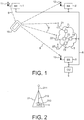
- the system shown merely by way of non-limiting example in Fig. 1 comprises base stations (BS) 1, 2 and 3, a mobile telecommunication device 10 and a data network 7.
- the mobile telecommunication device 10 may be a mobile (i.e. cellular) telephone, a smartphone, a portable computer provided with telephone facilities, or any other portable communication device capable of transmitting a communication signal S which can be received by the base stations 1, 2 and 3.
- Each base station is configured for supporting mobile (that is cellular) telecommunications, for example telecommunications in accordance with LTE (Long Term Evolution) or 4G.
- the base stations are part of a wireless communication network wherein they perform functions of transmission and reception of wireless signals as part of the wireless communication network operation. Accordingly, each base station defines a geographic wireless cell of the wireless communication network in which wireless telecommunication through the wireless communication network is supported via the base station.
- the base stations 1, 2 and 3 are connected by a data link 8, which allows the base station to exchange information and, in particular, allows the base stations to receive reference signals.
- the data link 8 preferably is a wired link (e.g. a data cable) but may also be constituted by a wireless link.
- the data network 7 is coupled to the link 8 as well.
- a central unit (CU) 9 is also coupled to the link 8, thus allowing the base stations 1, 2 and 3 to communicate with the central unit 9 and the data network 7.
- the central unit 9 may be constituted by a suitably configured computer unit and may be capable of receiving information from the base stations, processing that information and supplying selected information, for example a location, to a device capable of displaying the selected information.
- a suitable display unit may be part of the central unit 9.
- the central unit 9 carries out the reference signal selection and processing tasks that are carried out by the base stations in other embodiments.
- the data network may be a conventional data network capable of digitally transferring data.
- the data network 7 shown in Fig. 1 comprises a plurality of switching units 71, 72, 73, ... which are connected by suitable data links.
- switching unit 74 is connected to the link 8.
- Receiver units 21, 22 and 23 are connected to the switching units 71, 72, 73 and 74 respectively and serve to receive the signal S so as to provide a reference signal, as will later be explained in more detail with reference to Fig. 3 .
- Each base station 1, 2 and 3 is provided with an antenna 11, 12 and 13 respectively for receiving the signal S transmitted by the mobile telecommunication device 10. Accordingly, each base station receives the signal S directly via its antenna and indirectly via the data network 7 and its receiver units 21, 22 and 23.
- the indirectly received signal S' which during the wireless part of its transmission is identical to the original signal S, is used as reference signal.
- the reference signal S' will typically reach a base station later than the original signal S, even if a receiver unit is closer to the mobile telecommunication device than the base station antenna is.
- the original signal S is delayed in the base stations, at least until the reference signal S' is received by the respective base station.
- Delaying the reference signal S' is preferably achieved by temporarily storing this signal. That is, the reference signal S' is stored in a memory unit of each base station, at least until it can be compared with the original signal S. This will later be explained in more detail with reference to Figs. 4 and 5 .
- the system may comprise more than three base stations.
- at least three base stations are required, which base stations must be sufficiently spaced apart.
- the base stations may be conventional base stations used for UMTS, LTE or similar mobile telecommunication systems. However, in preferred embodiments the base stations are dedicated base stations configured for indoor use. Advantageously, the base stations may be configured both for general (e.g. LTE) and indoor (e.g. WLAN) use.
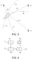
- FIG. 2 An exemplary embodiment of a receiver unit is schematically illustrated in Fig. 2 .
- the receiver unit of Fig. 2 comprises an antenna 211 and an A/D (analogue/digital) converter 213 which are connected by a cable 212 (in some embodiments, this connection may be wireless).
- the antenna 211 receives the analogue signal S' which is converted into a digital signal by the A/D converter 213 and forwarded to the data network 7 ( Fig. 1 ).
- no further signal processing takes place, except from preferably limiting the time duration of the signal. That is, preferably a time-limited section of the digitised signal S' is forwarded rather than a continuous stream.
- the time-limited signal section may have a duration of less than 1 ms (millisecond), preferably less than 0.1 ms. In some embodiments, the signal section may have a duration of a few microseconds.
- the digital signal may be compressed to facilitate its transmission, preferably using lossless compression.
- the A/D unit 213 may be provided with a signal compression unit which may use conventional signal compression (i.e. coding) techniques. It will be understood that the receiver units may additionally comprise an interface unit (not shown) for interfacing with the data network 7.
- the base stations operate as part of a wireless communication network wherein they perform functions of transmission and reception of wireless signals in wireless network telecommunication for their geographic area.
- the receiver units 21-23 are not configured for mobile telecommunication but may be configured for wireless communication with portable devices.
- the wireless telecommunication network operation in a cell that contains the receiver units 21-23 proceeds without involvement of the receiver units 21-23 in that cell.
- the receiver units are inexpensive units. This allows a relatively large number of receiver units to be installed, if desired, for example a plurality in the same wireless network cell.
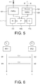
- Fig. 3 which shows parts of the system of Fig. 1 , schematically illustrates various aspects.
- the mobile communication device 10 is located at a distance D1 from the antenna 11 of the first base station (1 in Fig. 1 ), and at distances D2 and D3 from the antennas 12 and 13 of the second and third base stations (2 and 3 in Fig. 1 ) respectively.
- the distances D1, D2 and D3 can be determined, or at least the differences between those distances, as will be explained in more detail below.
- hyperbolic navigation The principles of multilateration, also known as hyperbolic navigation are used.
- Each pair of base stations determines a time difference between the arrival of the signal S at the respective base stations (or, more precisely, at their antennas), each time difference being caused by a difference in distance to the source of the signal, that is, the mobile communication device 10.
- this time difference results in a hyperbola on which the origin of the signal S, here the mobile communication device 10, is located.
- hyperbola H1 is defined by the base station pair 1, 2 while hyperbola H2 is defined by the base station pair 2, 3.
- the intersection of two hyperbolas H1, H2 indicates the position of the device 10.
- the hyperbolas H1 and H2 are determined relative to the positions of the base stations, resulting in a relative position. Preferably, however, the locations of the base stations are known and as a result, the found position of the mobile communication device will be an absolute position.
- the moments in time at which the signals reach the antennas 11, 12 and 13 of their associated base stations 1, 2 and 3 respectively are determined by correlating the wirelessly received original signal S and the reference signal S' received via the data network 7. Although this correlation may be carried out in the central unit, it is preferred that it is carried out in the base stations, as this reduces the required transfer of data.
- Fig. 4 schematically illustrates how the original signal S and the reference signal S' may be processed in a base station.
- the reference signal S' typically reaches the base stations later than the original signal S.
- the original signal S is delayed (D) in step 151.
- the delay is chosen so as to approximately correspond to an expected delay of the reference signal S' in the data network (7 in Fig. 1 ). This will allow the corresponding parts of the reference signal and the original signal to be correlated.
- the delay may be embodied by a shift register or similar structure, or by a memory in which the signal is temporarily stored.
- step 152 the reference signal S' and the (delayed) original signal S are correlated (p), resulting in a time tr which is indicative of the correlation peak relative to the beginning of the signal S. It is noted that the arrival of the signal S, or of a particular part of signal S, should be registered to allow the relative position of the correlation peak to be determined.
- step 153 a clock time tc is retrieved and in step 154, the temporal occurrence of the correlation peak tr is combined with the clock time tc to produce the time of arrival ta for the base station.
- This time of arrival ta is used in further steps (not shown) together with times of arrival produced by the other base stations to determine time of arrival differences, which in turn are used to produce differences in distances travelled and the hyperbolas illustrated in Fig. 1 .
- the base station 1 comprises a first signal reception unit (FSRU) 101, a second signal reception unit (SSRU) 102, a network interface unit (NIU) 103, a processor (P) 110, a memory (M) 111 and a clock (C) 115.
- the network interface unit 103 is integral with the second signal reception unit 102.
- a single integrated signal reception unit may replace the first and second signal reception units 101 and 102, and/or a delay unit (not shown) may be arranged between the first signal reception unit 101 and the processor 110.
- the first signal reception unit 101 receives the original signal S from the antenna 11 while the second signal reception unit 102 receives the reference signal S' from the link 8 via the network interface unit 103.
- the link 8 connects the base stations with the data network 7 to which in turn the receivers 21 are connected.
- Multiple versions of the reference signal S' may reach the base station 1, as there are multiple receivers (21-23 in Fig. 1 ) which may receive the signal.
- the base station selects (the version of) the reference signal S' having the highest signal quality, thus rejecting all others.
- the processor 110 of the base station may be configured to determine the signal-to-noise (S/N) ratio of (the various versions of) the reference signal S' and/or other signal parameters and then to select the best available in terms of the applied quality criteria.
- the original signal S is delayed (that is, temporarily stored) in the base stations.
- a section of the original signal S is stored, together with the moment in time (measured by the local clock of the base station) at which the beginning of this section was received.
- the memory unit 111 stores suitable processor instructions for carrying out the required signal processing steps and also stores the original signal S.
- the signal processing steps include correlating the original signal S and the reference signal S'. As the original signal S and the reference signal S' are essentially the same signal, the correlation will be low unless the signal sections are properly aligned in time, at which point the correlation will exhibit a peak.
- the time shift of the two signal sections is a precise measure of the delay of the original signal as it covered the distance (D1 in Fig. 3 ) from the mobile communication device to the base station 1.
- the processor 110 will produce a time indication derived from the correlation peak. This time indication is combined with the local time indicated by the clock 115 and is in base stations 2 and 3 corrected by a correction factor, the so-called time deviation, as will be explained below.
- the base stations exchange timing messages which are provided to determine any deviations of the clocks.
- the clocks will not be perfectly synchronised and this is not even necessary if the deviations can be determined with sufficient accuracy.
- the timing messages contain the (local) times of transmission.
- ⁇ 2 is the time deviation of the second base station
- tt1 and tt2 are the times of transmission at a first and a second base station respectively
- tr1 and tr2 are the times of receipt at the first and the second base station respectively.
- any deviations of the local clocks of the base stations can be determined. These deviations can, in turn, be used to compensate any delay times and hence compensate the distances used for determining the position of the mobile communication device.
- the insight is used that a reference signal for correlation purposes can advantageously be transmitted via a digital network.
- the further insight is used that differences between local clocks in base stations can be determined in a simple yet very effective manner.
- the present invention is suitable for indoor use.
- any terms used in this document should not be construed so as to limit the scope of the present invention.
- the words “comprise(s)” and “comprising” are not meant to exclude any elements not specifically stated.
- Single (circuit) elements may be substituted with multiple (circuit) elements or with their equivalents.
- the words “location” and “position” can be used interchangeably.
Landscapes
- Engineering & Computer Science (AREA)
- Signal Processing (AREA)
- Computer Networks & Wireless Communication (AREA)
- Physics & Mathematics (AREA)
- General Physics & Mathematics (AREA)
- Radar, Positioning & Navigation (AREA)
- Remote Sensing (AREA)
- Mobile Radio Communication Systems (AREA)
- Position Fixing By Use Of Radio Waves (AREA)
Claims (13)
- Procédé de détermination d'une position d'un dispositif de télécommunication mobile (10) qui transmet un signal (S) à des stations de base (1, 2, 3, ...) connectées par une liaison de données (8) et ayant des emplacements connus, les stations de base (1, 2, ...) étant conçues pour exécuter des fonctions de transmission et de réception de signaux sans fil dans le cadre du fonctionnement d'un réseau de communication sans fil, le procédé comprenant les étapes de :• réception du signal (S) au niveau de deux stations de base ou plus (1, 2, ...) sans fil via une antenne (11, 12, 13) de la station de base (1, 2, ...),• fourniture d'un signal de référence (S') au niveau des stations de base,• corrélation du signal (S) et du signal de référence (S') de manière à produire une corrélation pour chaque station de base,• détection d'un maximum dans chaque corrélation, lequel maximum est indicatif d'une heure d'arrivée du signal (S) à la station de base respective,• dérivation à partir des heures d'arrivée de distances respectives (D1, D2, ...) au dispositif de communication mobile (10) et,• utilisation des distances respectives (D1, D2, ...) et des emplacements connus respectifs des stations de base pour dériver un emplacement du dispositif de télécommunication mobile à partir des distances respectives (D1, D2, ...), caractérisé par• la fourniture d'un réseau de données (7) couplé à la liaison de données (8),• la fourniture de récepteurs (21, 22, ...), qui n'interviennent pas dans le fonctionnement du réseau de communication sans fil, les récepteurs (21, 22, ...) étant couplés au réseau de données (7),• la réception en outre du signal (8) avec les récepteurs (21, 22, ..),• la dérivation de signaux numérisés à partir des signaux (S) tels que reçus par chaque récepteur (21, 22, ...) en utilisant une conversion A/N, le signal numérisé étant une version numérisée du signal reçu non obtenue par reconstruction ou remodulation du signal reçu, et• la transmission des signaux numérisés, ou d'une compression sans perte de ceux-ci, des récepteurs (21, 22, ..) aux stations de base via le réseau de données (7) et la liaison de données (8),• chaque station de base (1, 2, ..) sélectionnant le signal numérisé ayant la qualité la plus élevée pour une utilisation comme signal de référence (S') dans ladite étape de corrélation, si elle reçoit plusieurs signaux numérisés.
- Procédé selon la revendication 1, dans lequel les récepteurs transmettent une section limitée dans le temps du signal numérisé (S') aux stations de base.
- Procédé selon l'une quelconque des revendications précédentes, dans lequel le réseau de données (7) et les récepteurs (21, 22, ...) sont conçus pour un accès au réseau local sans fil.
- Procédé selon la revendication 1, comprenant en outre l'étape de détermination du rapport signal sur bruit du signal numérisé de manière à sélectionner le signal de référence ayant la qualité la plus élevée.
- Procédé selon l'une quelconque des revendications précédentes, dans lequel le signal (S) est un signal de communication numérique modulé.
- Procédé selon l'une quelconque des revendications précédentes, dans lequel le signal (S) est un signal continu.
- Procédé selon l'une quelconque des revendications précédentes, comprenant en outre les étapes de :• fourniture d'une horloge locale (115) dans chaque station de base pour déterminer les heures d'arrivée du signal (S),• échange de messages de synchronisation entre les stations de base,• dérivation à partir des messages de synchronisation d'éventuels écarts de temps (ε1, ε2, ...) des horloges locales, et• détermination de l'heure d'arrivée du signal (S) à chaque station de base à l'aide de l'horloge locale respective et de l'écart temporel respectif.
- Procédé selon la revendication 7, comprenant en outre les étapes de :• chaque station de base émettrice enregistrant l'heure de transmission (tt1, tt2, ...) de chaque message de synchronisation, et• chaque station de base réceptrice enregistrant l'heure de réception (tr1, tr2, ...) de chaque message de synchronisation,• détermination de l'écart temporel (ε2) d'une deuxième station de base (2) par rapport à une première station de base (1) par ε2 = (tr1 + tt1 - tt2 - tr2)/2.
- Procédé selon la revendication 7 ou 8, dans lequel les messages de synchronisation contiennent l'heure d'émission (tt1, tt2, ...) au niveau de la station de base émettrice.
- Procédé selon l'une quelconque des revendications 7 à 9, dans lequel les messages de synchronisation sont constitués par des signaux en forme d'impulsion qui sont de préférence transmis sans fil.
- Procédé selon l'une quelconque des revendications 7 à 10, dans lequel les messages de synchronisation sont constitués par des signaux modulés en fréquence, de préférence des signaux ayant un balayage de fréquence linéaire.
- Produit programme informatique, comprenant des instructions pour amener le système selon la revendication 13 à exécuter les étapes du procédé selon la revendication 1.
- Système pour déterminer une position d'un dispositif de télécommunication mobile (10) qui transmet un signal (S), le système comprenant• au moins trois stations de base (1, 2, ...), chaque station de base (1, 2, ...) à utiliser dans un système de télécommunication mobile, les stations de base (1, 2, ...) étant conçues pour exécuter des fonctions de transmission et de réception de signaux sans fil dans le cadre du fonctionnement d'un réseau de communication sans fil, chaque station de base comprend :• une première unité de réception de signal (101) pour recevoir sans fil un signal (S) du dispositif de télécommunication mobile (10),• une pluralité de récepteurs de signaux (21, 22, ..), qui n'interviennent pas dans le fonctionnement du réseau sans fil, chacun étant conçu pour recevoir en outre le signal (S) du dispositif de télécommunication mobile (10) et pour transmettre des signaux numérisés (S'), ou une compression sans perte de celui-ci, à des stations de base via un réseau de données (7) et une liaison de données (8), le signal numérisé (S') étant dérivé du signal reçu par le récepteur de signal (21, 22, ..) en utilisant une conversion A/N, le signal numérisé étant une version numérisée du signal reçu non obtenue par reconstruction ou remodulation du signal reçu, dans lequel• chaque station de base comprend en outre : une deuxième unité de réception de signal (102) comprenant une unité d'interface réseau (103) pour s'interfacer, via la liaison de données (8), avec le réseau de données (7) auquel sont couplés les récepteurs de signaux (21, 22, ...), pour recevoir les signaux numérisés provenant des récepteurs de signaux (21, 22, ..),• une unité de mémoire (111) pour stocker le signal (S), et• une unité de processeur (110) pour traiter le signal (S) et un signal de référence (S'),et étant conçue pour :• sélectionner le signal numérisé ayant la qualité la plus élevée à utiliser comme signal de référence (S'), si elle reçoit plusieurs signaux numérisés,• corréler le signal (S) et le signal de référence (S') de manière à produire une corrélation pour chaque station de base,• détecter un maximum dans chaque corrélation, lequel maximum est indicatif d'une heure d'arrivée du signal (S) à la station de base respective,• dériver à partir des heures d'arrivée des distances respectives (D1, D2, ...) au dispositif de télécommunication mobile (10) et,• utiliser les distances respectives (D1, D2, ...) et les emplacements connus respectifs pour dériver un emplacement du dispositif de télécommunication mobile.
Priority Applications (1)
| Application Number | Priority Date | Filing Date | Title |
|---|---|---|---|
| EP14703929.1A EP2951608B1 (fr) | 2013-01-31 | 2014-01-31 | Détermination de position d'un dispositif de communication mobile |
Applications Claiming Priority (3)
| Application Number | Priority Date | Filing Date | Title |
|---|---|---|---|
| EP13153445 | 2013-01-31 | ||
| EP14703929.1A EP2951608B1 (fr) | 2013-01-31 | 2014-01-31 | Détermination de position d'un dispositif de communication mobile |
| PCT/NL2014/050060 WO2014120012A1 (fr) | 2013-01-31 | 2014-01-31 | Détermination de la position d'un dispositif mobile de communication |
Publications (2)
| Publication Number | Publication Date |
|---|---|
| EP2951608A1 EP2951608A1 (fr) | 2015-12-09 |
| EP2951608B1 true EP2951608B1 (fr) | 2021-03-10 |
Family
ID=47678606
Family Applications (1)
| Application Number | Title | Priority Date | Filing Date |
|---|---|---|---|
| EP14703929.1A Active EP2951608B1 (fr) | 2013-01-31 | 2014-01-31 | Détermination de position d'un dispositif de communication mobile |
Country Status (3)
| Country | Link |
|---|---|
| US (3) | US10812933B2 (fr) |
| EP (1) | EP2951608B1 (fr) |
| WO (1) | WO2014120012A1 (fr) |
Families Citing this family (9)
| Publication number | Priority date | Publication date | Assignee | Title |
|---|---|---|---|---|
| EP2951608B1 (fr) | 2013-01-31 | 2021-03-10 | Nederlandse Organisatie voor toegepast- natuurwetenschappelijk onderzoek TNO | Détermination de position d'un dispositif de communication mobile |
| US10989788B2 (en) * | 2016-11-17 | 2021-04-27 | Lion Group, Inc. | Radio frequency identification (RFID) system for determining location |
| US10511929B2 (en) * | 2017-09-14 | 2019-12-17 | Qualcomm Incorporated | Opportunistic signal reception for mobile device position location estimation |
| CN111869291B (zh) | 2018-02-02 | 2025-05-09 | 康奈尔大学 | 无线系统中的信道制图 |
| CN110798854B (zh) * | 2018-08-03 | 2021-10-26 | 上海华为技术有限公司 | 一种时钟状态检测方法及装置 |
| US11546735B2 (en) * | 2020-08-25 | 2023-01-03 | Sr Technologies, Inc. | Peak to sigma ratio measurement with active geo-location for wireless local area network devices |
| WO2022260575A1 (fr) * | 2021-06-08 | 2022-12-15 | Delaval Holding Ab | Système, procédé de positionnement mis en œuvre par ordinateur, programme informatique et support de données non volatil |
| US20250193823A1 (en) * | 2022-03-11 | 2025-06-12 | Nokia Technologies Oy | Positioning reference unit selection |
| CN115243193B (zh) * | 2022-07-08 | 2024-04-16 | 中国联合网络通信集团有限公司 | 受激干扰源的位置确定方法、装置及计算机可读存储介质 |
Family Cites Families (19)
| Publication number | Priority date | Publication date | Assignee | Title |
|---|---|---|---|---|
| US5327144A (en) | 1993-05-07 | 1994-07-05 | Associated Rt, Inc. | Cellular telephone location system |
| US6047192A (en) | 1996-05-13 | 2000-04-04 | Ksi Inc. | Robust, efficient, localization system |
| US6249680B1 (en) | 1997-01-08 | 2001-06-19 | U.S. Wireless Corporation | Radio transmitter location finding in CDMA wireless communication systems |
| KR100378124B1 (ko) | 1998-12-10 | 2003-06-19 | 삼성전자주식회사 | 이동통신시스템에서단말기의위치추정장치및방법 |
| US6184829B1 (en) | 1999-01-08 | 2001-02-06 | Trueposition, Inc. | Calibration for wireless location system |
| DE60142846D1 (de) | 2000-11-14 | 2010-09-30 | Symbol Technologies Inc | Verfahren und system zur lokalisierung eines mobilfunkgeräts |
| US6876859B2 (en) * | 2001-07-18 | 2005-04-05 | Trueposition, Inc. | Method for estimating TDOA and FDOA in a wireless location system |
| US7269427B2 (en) * | 2001-10-09 | 2007-09-11 | General Electric Company | Transmitter location for ultra-wideband, transmitted-reference CDMA communication system |
| CN100362365C (zh) | 2003-02-07 | 2008-01-16 | 西门子公司 | 无线通信系统中的用户定位方法 |
| DE10305091B4 (de) | 2003-02-07 | 2005-02-03 | Siemens Ag | Verfahren zur Positionsbestimmung eines Teilnehmers in einem Funkkommunikationssystem |
| FR2902195B1 (fr) | 2006-06-09 | 2010-04-09 | Thales Sa | Procede de determination de l'instant d'arrivee d'un signal radioelectrique non impulsionnel et systeme de localisation geographique d'emetteurs de signaux radioelectriques non impulsionnels |
| EP1978771A1 (fr) | 2007-04-05 | 2008-10-08 | Nederlandse Organisatie voor Toegepast-Natuuurwetenschappelijk Onderzoek TNO | Détection d'emplacement |
| US7924224B2 (en) | 2008-08-15 | 2011-04-12 | Trueposition, Inc. | Variable coherence integration for the location of weak signals |
| US7990317B2 (en) | 2009-12-18 | 2011-08-02 | At&T Mobility Ii Llc | Signal path delay determination |
| US8526391B2 (en) * | 2010-07-23 | 2013-09-03 | Trueposition, Inc. | Network based location of mobile transmitters |
| WO2012081740A1 (fr) * | 2010-12-14 | 2012-06-21 | Choi Ok Jae | Procédé d'envoi d'un signal de référence et système de mesure d'emplacement, procédé de mesure d'emplacement, dispositif et système utilisant ce dernier, et procédé de synchronisation temporelle et dispositif utilisant ce dernier |
| EP2487503B1 (fr) | 2011-02-11 | 2013-10-02 | Friedrich-Alexander-Universität Erlangen-Nürnberg | Appareil et procédé de localisation |
| US8971924B2 (en) * | 2011-05-23 | 2015-03-03 | Apple Inc. | Identifying and locating users on a mobile network |
| EP2951608B1 (fr) | 2013-01-31 | 2021-03-10 | Nederlandse Organisatie voor toegepast- natuurwetenschappelijk onderzoek TNO | Détermination de position d'un dispositif de communication mobile |
-
2014
- 2014-01-31 EP EP14703929.1A patent/EP2951608B1/fr active Active
- 2014-01-31 WO PCT/NL2014/050060 patent/WO2014120012A1/fr not_active Ceased
- 2014-01-31 US US14/765,059 patent/US10812933B2/en active Active
-
2020
- 2020-09-17 US US17/024,641 patent/US11540085B2/en active Active
-
2022
- 2022-11-23 US US17/993,090 patent/US11716591B2/en active Active
Non-Patent Citations (1)
| Title |
|---|
| None * |
Also Published As
| Publication number | Publication date |
|---|---|
| US11716591B2 (en) | 2023-08-01 |
| US20210112370A1 (en) | 2021-04-15 |
| US20230082438A1 (en) | 2023-03-16 |
| EP2951608A1 (fr) | 2015-12-09 |
| US11540085B2 (en) | 2022-12-27 |
| US10812933B2 (en) | 2020-10-20 |
| US20150373494A1 (en) | 2015-12-24 |
| WO2014120012A1 (fr) | 2014-08-07 |
Similar Documents
| Publication | Publication Date | Title |
|---|---|---|
| US11716591B2 (en) | Determining a position of a mobile communication device | |
| Keating et al. | Overview of positioning in 5G new radio | |
| US7627327B2 (en) | Network overlay location system and method for air interface with frequency hopping | |
| US10101434B2 (en) | Positioning method, control device, and mobile communications system | |
| CN103139905B (zh) | 对用户设备进行定位的方法和装置 | |
| EP2673985B1 (fr) | Levé d'ambiguïté de l'assistance au positionnement par le côté équipement utilisateur | |
| JP2021519422A (ja) | 位置サービスのためのネットワークアーキテクチャ及び方法 | |
| US20110312339A1 (en) | Methods and Arrangements in a Wireless Communication System | |
| US8761806B2 (en) | Method, system and device for implementing positioning measurement | |
| US20150230263A1 (en) | Method for millimeter wave beam tracking | |
| EP3621351A1 (fr) | Système, dispositif, appareil, procédé de configuration de données d'aide au positionnement, et support d'informations | |
| JP4772868B2 (ja) | 移動端末が所定の場所の外側に移動したかどうか判定するための方法及び装置 | |
| US20110039575A1 (en) | Method and system for positioning neighbor cells in a cellular network using learned cell data | |
| EP2763478A1 (fr) | Procédé et dispositif utilisant une différence de temps d'arrivée observée pour localiser une station mobile | |
| US20240159855A1 (en) | Methods and signaling for enabling carrier phase-based positioning in a wireless communication system | |
| JP6639237B2 (ja) | 方法、位置ネットワークセンタ、及び位置ネットワーク受信機 | |
| WO2019110302A1 (fr) | Procédé de positionnement d'un équipement utilisateur fonctionnant dans un réseau cellulaire | |
| EP3874616B1 (fr) | Appareil et procédé d'estimation de position d'ue | |
| CN114449643B (zh) | 用于时间同步的装置和方法 | |
| KR101855378B1 (ko) | 이종망 이동통신을 이용한 무선 측위 방법 | |
| WO2025068285A1 (fr) | Positionnement d'un ue à l'aide d'une pluralité de systèmes de communication aérienne | |
| Partner | Performance of 3GPP Rel-9 LTE positioning methods |
Legal Events
| Date | Code | Title | Description |
|---|---|---|---|
| PUAI | Public reference made under article 153(3) epc to a published international application that has entered the european phase |
Free format text: ORIGINAL CODE: 0009012 |
|
| 17P | Request for examination filed |
Effective date: 20150806 |
|
| AK | Designated contracting states |
Kind code of ref document: A1 Designated state(s): AL AT BE BG CH CY CZ DE DK EE ES FI FR GB GR HR HU IE IS IT LI LT LU LV MC MK MT NL NO PL PT RO RS SE SI SK SM TR |
|
| AX | Request for extension of the european patent |
Extension state: BA ME |
|
| DAX | Request for extension of the european patent (deleted) | ||
| STAA | Information on the status of an ep patent application or granted ep patent |
Free format text: STATUS: EXAMINATION IS IN PROGRESS |
|
| 17Q | First examination report despatched |
Effective date: 20180328 |
|
| RIC1 | Information provided on ipc code assigned before grant |
Ipc: G01S 5/06 20060101ALI20200331BHEP Ipc: H04W 56/00 20090101ALI20200331BHEP Ipc: G01S 5/02 20100101AFI20200331BHEP Ipc: H04W 4/02 20180101ALI20200331BHEP |
|
| GRAP | Despatch of communication of intention to grant a patent |
Free format text: ORIGINAL CODE: EPIDOSNIGR1 |
|
| STAA | Information on the status of an ep patent application or granted ep patent |
Free format text: STATUS: GRANT OF PATENT IS INTENDED |
|
| INTG | Intention to grant announced |
Effective date: 20200928 |
|
| RIN1 | Information on inventor provided before grant (corrected) |
Inventor name: ELFERINK, FRANCISCUS, HENDRIKUS Inventor name: VAN RIJN, MARTIN |
|
| GRAS | Grant fee paid |
Free format text: ORIGINAL CODE: EPIDOSNIGR3 |
|
| GRAA | (expected) grant |
Free format text: ORIGINAL CODE: 0009210 |
|
| STAA | Information on the status of an ep patent application or granted ep patent |
Free format text: STATUS: THE PATENT HAS BEEN GRANTED |
|
| AK | Designated contracting states |
Kind code of ref document: B1 Designated state(s): AL AT BE BG CH CY CZ DE DK EE ES FI FR GB GR HR HU IE IS IT LI LT LU LV MC MK MT NL NO PL PT RO RS SE SI SK SM TR |
|
| REG | Reference to a national code |
Ref country code: GB Ref legal event code: FG4D |
|
| REG | Reference to a national code |
Ref country code: CH Ref legal event code: EP Ref country code: AT Ref legal event code: REF Ref document number: 1370428 Country of ref document: AT Kind code of ref document: T Effective date: 20210315 |
|
| REG | Reference to a national code |
Ref country code: DE Ref legal event code: R096 Ref document number: 602014075535 Country of ref document: DE |
|
| REG | Reference to a national code |
Ref country code: IE Ref legal event code: FG4D |
|
| REG | Reference to a national code |
Ref country code: NL Ref legal event code: FP |
|
| REG | Reference to a national code |
Ref country code: DE Ref legal event code: R081 Ref document number: 602014075535 Country of ref document: DE Owner name: K.MIZRA LLC, MIAMI, US Free format text: FORMER OWNER: DATASERVE TECHNOLOGIES LLC, WILMINGTON, DE, US Ref country code: DE Ref legal event code: R081 Ref document number: 602014075535 Country of ref document: DE Owner name: K.MIZRA LLC, MIAMI, US Free format text: FORMER OWNER: NEDERLANDSE ORGANISATIE VOOR TOEGEPAST-NATUURWETENSCHAPPELIJK ONDERZOEK TNO, 'S-GRAVENHAGE, NL Ref country code: DE Ref legal event code: R082 Ref document number: 602014075535 Country of ref document: DE Representative=s name: BOSCH JEHLE PATENTANWALTSGESELLSCHAFT MBH, DE Ref country code: DE Ref legal event code: R081 Ref document number: 602014075535 Country of ref document: DE Owner name: K.MIZRA LLC, LOS ANGELES, US Free format text: FORMER OWNER: NEDERLANDSE ORGANISATIE VOOR TOEGEPAST-NATUURWETENSCHAPPELIJK ONDERZOEK TNO, 'S-GRAVENHAGE, NL Ref country code: DE Ref legal event code: R081 Ref document number: 602014075535 Country of ref document: DE Owner name: K.MIZRA LLC, LOS ANGELES, US Free format text: FORMER OWNER: DATASERVE TECHNOLOGIES LLC, WILMINGTON, DE, US |
|
| REG | Reference to a national code |
Ref country code: LT Ref legal event code: MG9D |
|
| PG25 | Lapsed in a contracting state [announced via postgrant information from national office to epo] |
Ref country code: NO Free format text: LAPSE BECAUSE OF FAILURE TO SUBMIT A TRANSLATION OF THE DESCRIPTION OR TO PAY THE FEE WITHIN THE PRESCRIBED TIME-LIMIT Effective date: 20210610 Ref country code: BG Free format text: LAPSE BECAUSE OF FAILURE TO SUBMIT A TRANSLATION OF THE DESCRIPTION OR TO PAY THE FEE WITHIN THE PRESCRIBED TIME-LIMIT Effective date: 20210610 Ref country code: LT Free format text: LAPSE BECAUSE OF FAILURE TO SUBMIT A TRANSLATION OF THE DESCRIPTION OR TO PAY THE FEE WITHIN THE PRESCRIBED TIME-LIMIT Effective date: 20210310 Ref country code: FI Free format text: LAPSE BECAUSE OF FAILURE TO SUBMIT A TRANSLATION OF THE DESCRIPTION OR TO PAY THE FEE WITHIN THE PRESCRIBED TIME-LIMIT Effective date: 20210310 Ref country code: HR Free format text: LAPSE BECAUSE OF FAILURE TO SUBMIT A TRANSLATION OF THE DESCRIPTION OR TO PAY THE FEE WITHIN THE PRESCRIBED TIME-LIMIT Effective date: 20210310 Ref country code: GR Free format text: LAPSE BECAUSE OF FAILURE TO SUBMIT A TRANSLATION OF THE DESCRIPTION OR TO PAY THE FEE WITHIN THE PRESCRIBED TIME-LIMIT Effective date: 20210611 |
|
| REG | Reference to a national code |
Ref country code: GB Ref legal event code: 732E Free format text: REGISTERED BETWEEN 20210715 AND 20210721 |
|
| REG | Reference to a national code |
Ref country code: AT Ref legal event code: MK05 Ref document number: 1370428 Country of ref document: AT Kind code of ref document: T Effective date: 20210310 |
|
| PG25 | Lapsed in a contracting state [announced via postgrant information from national office to epo] |
Ref country code: SE Free format text: LAPSE BECAUSE OF FAILURE TO SUBMIT A TRANSLATION OF THE DESCRIPTION OR TO PAY THE FEE WITHIN THE PRESCRIBED TIME-LIMIT Effective date: 20210310 Ref country code: LV Free format text: LAPSE BECAUSE OF FAILURE TO SUBMIT A TRANSLATION OF THE DESCRIPTION OR TO PAY THE FEE WITHIN THE PRESCRIBED TIME-LIMIT Effective date: 20210310 Ref country code: RS Free format text: LAPSE BECAUSE OF FAILURE TO SUBMIT A TRANSLATION OF THE DESCRIPTION OR TO PAY THE FEE WITHIN THE PRESCRIBED TIME-LIMIT Effective date: 20210310 |
|
| PG25 | Lapsed in a contracting state [announced via postgrant information from national office to epo] |
Ref country code: SM Free format text: LAPSE BECAUSE OF FAILURE TO SUBMIT A TRANSLATION OF THE DESCRIPTION OR TO PAY THE FEE WITHIN THE PRESCRIBED TIME-LIMIT Effective date: 20210310 Ref country code: AT Free format text: LAPSE BECAUSE OF FAILURE TO SUBMIT A TRANSLATION OF THE DESCRIPTION OR TO PAY THE FEE WITHIN THE PRESCRIBED TIME-LIMIT Effective date: 20210310 Ref country code: EE Free format text: LAPSE BECAUSE OF FAILURE TO SUBMIT A TRANSLATION OF THE DESCRIPTION OR TO PAY THE FEE WITHIN THE PRESCRIBED TIME-LIMIT Effective date: 20210310 Ref country code: CZ Free format text: LAPSE BECAUSE OF FAILURE TO SUBMIT A TRANSLATION OF THE DESCRIPTION OR TO PAY THE FEE WITHIN THE PRESCRIBED TIME-LIMIT Effective date: 20210310 |
|
| PG25 | Lapsed in a contracting state [announced via postgrant information from national office to epo] |
Ref country code: SK Free format text: LAPSE BECAUSE OF FAILURE TO SUBMIT A TRANSLATION OF THE DESCRIPTION OR TO PAY THE FEE WITHIN THE PRESCRIBED TIME-LIMIT Effective date: 20210310 Ref country code: RO Free format text: LAPSE BECAUSE OF FAILURE TO SUBMIT A TRANSLATION OF THE DESCRIPTION OR TO PAY THE FEE WITHIN THE PRESCRIBED TIME-LIMIT Effective date: 20210310 Ref country code: PT Free format text: LAPSE BECAUSE OF FAILURE TO SUBMIT A TRANSLATION OF THE DESCRIPTION OR TO PAY THE FEE WITHIN THE PRESCRIBED TIME-LIMIT Effective date: 20210712 Ref country code: PL Free format text: LAPSE BECAUSE OF FAILURE TO SUBMIT A TRANSLATION OF THE DESCRIPTION OR TO PAY THE FEE WITHIN THE PRESCRIBED TIME-LIMIT Effective date: 20210310 Ref country code: ES Free format text: LAPSE BECAUSE OF FAILURE TO SUBMIT A TRANSLATION OF THE DESCRIPTION OR TO PAY THE FEE WITHIN THE PRESCRIBED TIME-LIMIT Effective date: 20210310 Ref country code: IS Free format text: LAPSE BECAUSE OF FAILURE TO SUBMIT A TRANSLATION OF THE DESCRIPTION OR TO PAY THE FEE WITHIN THE PRESCRIBED TIME-LIMIT Effective date: 20210710 |
|
| REG | Reference to a national code |
Ref country code: DE Ref legal event code: R097 Ref document number: 602014075535 Country of ref document: DE |
|
| PLBE | No opposition filed within time limit |
Free format text: ORIGINAL CODE: 0009261 |
|
| STAA | Information on the status of an ep patent application or granted ep patent |
Free format text: STATUS: NO OPPOSITION FILED WITHIN TIME LIMIT |
|
| PG25 | Lapsed in a contracting state [announced via postgrant information from national office to epo] |
Ref country code: AL Free format text: LAPSE BECAUSE OF FAILURE TO SUBMIT A TRANSLATION OF THE DESCRIPTION OR TO PAY THE FEE WITHIN THE PRESCRIBED TIME-LIMIT Effective date: 20210310 Ref country code: DK Free format text: LAPSE BECAUSE OF FAILURE TO SUBMIT A TRANSLATION OF THE DESCRIPTION OR TO PAY THE FEE WITHIN THE PRESCRIBED TIME-LIMIT Effective date: 20210310 |
|
| 26N | No opposition filed |
Effective date: 20211213 |
|
| PG25 | Lapsed in a contracting state [announced via postgrant information from national office to epo] |
Ref country code: SI Free format text: LAPSE BECAUSE OF FAILURE TO SUBMIT A TRANSLATION OF THE DESCRIPTION OR TO PAY THE FEE WITHIN THE PRESCRIBED TIME-LIMIT Effective date: 20210310 |
|
| REG | Reference to a national code |
Ref country code: DE Ref legal event code: R081 Ref document number: 602014075535 Country of ref document: DE Owner name: K.MIZRA LLC, MIAMI, US Free format text: FORMER OWNER: K.MIZRA LLC, LOS ANGELES, CA, US |
|
| PG25 | Lapsed in a contracting state [announced via postgrant information from national office to epo] |
Ref country code: IT Free format text: LAPSE BECAUSE OF FAILURE TO SUBMIT A TRANSLATION OF THE DESCRIPTION OR TO PAY THE FEE WITHIN THE PRESCRIBED TIME-LIMIT Effective date: 20210310 |
|
| PG25 | Lapsed in a contracting state [announced via postgrant information from national office to epo] |
Ref country code: IS Free format text: LAPSE BECAUSE OF FAILURE TO SUBMIT A TRANSLATION OF THE DESCRIPTION OR TO PAY THE FEE WITHIN THE PRESCRIBED TIME-LIMIT Effective date: 20210710 |
|
| REG | Reference to a national code |
Ref country code: NL Ref legal event code: PD Owner name: DATASERVE TECHNOLOGIES LLC; US Free format text: DETAILS ASSIGNMENT: CHANGE OF OWNER(S), ASSIGNMENT; FORMER OWNER NAME: NEDERLANDSE ORGANISATIE VOOR TOEGEPAST- NATUURWETENSCHAPPELIJK ONDERZOEK TNO Effective date: 20220624 |
|
| PG25 | Lapsed in a contracting state [announced via postgrant information from national office to epo] |
Ref country code: MC Free format text: LAPSE BECAUSE OF FAILURE TO SUBMIT A TRANSLATION OF THE DESCRIPTION OR TO PAY THE FEE WITHIN THE PRESCRIBED TIME-LIMIT Effective date: 20210310 |
|
| REG | Reference to a national code |
Ref country code: CH Ref legal event code: PL |
|
| REG | Reference to a national code |
Ref country code: BE Ref legal event code: MM Effective date: 20220131 |
|
| PG25 | Lapsed in a contracting state [announced via postgrant information from national office to epo] |
Ref country code: LU Free format text: LAPSE BECAUSE OF NON-PAYMENT OF DUE FEES Effective date: 20220131 |
|
| PG25 | Lapsed in a contracting state [announced via postgrant information from national office to epo] |
Ref country code: FR Free format text: LAPSE BECAUSE OF NON-PAYMENT OF DUE FEES Effective date: 20220131 Ref country code: BE Free format text: LAPSE BECAUSE OF NON-PAYMENT OF DUE FEES Effective date: 20220131 |
|
| PG25 | Lapsed in a contracting state [announced via postgrant information from national office to epo] |
Ref country code: LI Free format text: LAPSE BECAUSE OF NON-PAYMENT OF DUE FEES Effective date: 20220131 Ref country code: CH Free format text: LAPSE BECAUSE OF NON-PAYMENT OF DUE FEES Effective date: 20220131 |
|
| PG25 | Lapsed in a contracting state [announced via postgrant information from national office to epo] |
Ref country code: IE Free format text: LAPSE BECAUSE OF NON-PAYMENT OF DUE FEES Effective date: 20220131 |
|
| P01 | Opt-out of the competence of the unified patent court (upc) registered |
Effective date: 20230524 |
|
| PG25 | Lapsed in a contracting state [announced via postgrant information from national office to epo] |
Ref country code: HU Free format text: LAPSE BECAUSE OF FAILURE TO SUBMIT A TRANSLATION OF THE DESCRIPTION OR TO PAY THE FEE WITHIN THE PRESCRIBED TIME-LIMIT; INVALID AB INITIO Effective date: 20140131 |
|
| PG25 | Lapsed in a contracting state [announced via postgrant information from national office to epo] |
Ref country code: MK Free format text: LAPSE BECAUSE OF FAILURE TO SUBMIT A TRANSLATION OF THE DESCRIPTION OR TO PAY THE FEE WITHIN THE PRESCRIBED TIME-LIMIT Effective date: 20210310 Ref country code: CY Free format text: LAPSE BECAUSE OF FAILURE TO SUBMIT A TRANSLATION OF THE DESCRIPTION OR TO PAY THE FEE WITHIN THE PRESCRIBED TIME-LIMIT Effective date: 20210310 |
|
| PG25 | Lapsed in a contracting state [announced via postgrant information from national office to epo] |
Ref country code: MT Free format text: LAPSE BECAUSE OF FAILURE TO SUBMIT A TRANSLATION OF THE DESCRIPTION OR TO PAY THE FEE WITHIN THE PRESCRIBED TIME-LIMIT Effective date: 20210310 |
|
| PGFP | Annual fee paid to national office [announced via postgrant information from national office to epo] |
Ref country code: NL Payment date: 20250127 Year of fee payment: 12 |
|
| PGFP | Annual fee paid to national office [announced via postgrant information from national office to epo] |
Ref country code: GB Payment date: 20250121 Year of fee payment: 12 |
|
| PG25 | Lapsed in a contracting state [announced via postgrant information from national office to epo] |
Ref country code: TR Free format text: LAPSE BECAUSE OF FAILURE TO SUBMIT A TRANSLATION OF THE DESCRIPTION OR TO PAY THE FEE WITHIN THE PRESCRIBED TIME-LIMIT Effective date: 20210310 |
|
| PGFP | Annual fee paid to national office [announced via postgrant information from national office to epo] |
Ref country code: DE Payment date: 20260127 Year of fee payment: 13 |