EP2951647B1 - Holographie optique synthétique - Google Patents
Holographie optique synthétique Download PDFInfo
- Publication number
- EP2951647B1 EP2951647B1 EP13841978.3A EP13841978A EP2951647B1 EP 2951647 B1 EP2951647 B1 EP 2951647B1 EP 13841978 A EP13841978 A EP 13841978A EP 2951647 B1 EP2951647 B1 EP 2951647B1
- Authority
- EP
- European Patent Office
- Prior art keywords
- field
- phase
- probe
- sample
- scanning
- Prior art date
- Legal status (The legal status is an assumption and is not a legal conclusion. Google has not performed a legal analysis and makes no representation as to the accuracy of the status listed.)
- Active
Links
Images









Classifications
-
- G—PHYSICS
- G03—PHOTOGRAPHY; CINEMATOGRAPHY; ANALOGOUS TECHNIQUES USING WAVES OTHER THAN OPTICAL WAVES; ELECTROGRAPHY; HOLOGRAPHY
- G03H—HOLOGRAPHIC PROCESSES OR APPARATUS
- G03H1/00—Holographic processes or apparatus using light, infrared or ultraviolet waves for obtaining holograms or for obtaining an image from them; Details peculiar thereto
- G03H1/04—Processes or apparatus for producing holograms
- G03H1/08—Synthesising holograms, i.e. holograms synthesized from objects or objects from holograms
-
- G—PHYSICS
- G01—MEASURING; TESTING
- G01B—MEASURING LENGTH, THICKNESS OR SIMILAR LINEAR DIMENSIONS; MEASURING ANGLES; MEASURING AREAS; MEASURING IRREGULARITIES OF SURFACES OR CONTOURS
- G01B9/00—Measuring instruments characterised by the use of optical techniques
- G01B9/02—Interferometers
- G01B9/021—Interferometers using holographic techniques
-
- G—PHYSICS
- G02—OPTICS
- G02B—OPTICAL ELEMENTS, SYSTEMS OR APPARATUS
- G02B21/00—Microscopes
- G02B21/0004—Microscopes specially adapted for specific applications
- G02B21/002—Scanning microscopes
- G02B21/0024—Confocal scanning microscopes (CSOMs) or confocal "macroscopes"; Accessories which are not restricted to use with CSOMs, e.g. sample holders
- G02B21/0032—Optical details of illumination, e.g. light-sources, pinholes, beam splitters, slits, fibers
-
- G—PHYSICS
- G02—OPTICS
- G02B—OPTICAL ELEMENTS, SYSTEMS OR APPARATUS
- G02B21/00—Microscopes
- G02B21/0004—Microscopes specially adapted for specific applications
- G02B21/002—Scanning microscopes
- G02B21/0024—Confocal scanning microscopes (CSOMs) or confocal "macroscopes"; Accessories which are not restricted to use with CSOMs, e.g. sample holders
- G02B21/0052—Optical details of the image generation
- G02B21/0056—Optical details of the image generation based on optical coherence, e.g. phase-contrast arrangements, interference arrangements
-
- G—PHYSICS
- G03—PHOTOGRAPHY; CINEMATOGRAPHY; ANALOGOUS TECHNIQUES USING WAVES OTHER THAN OPTICAL WAVES; ELECTROGRAPHY; HOLOGRAPHY
- G03H—HOLOGRAPHIC PROCESSES OR APPARATUS
- G03H1/00—Holographic processes or apparatus using light, infrared or ultraviolet waves for obtaining holograms or for obtaining an image from them; Details peculiar thereto
- G03H1/04—Processes or apparatus for producing holograms
- G03H1/0443—Digital holography, i.e. recording holograms with digital recording means
-
- G—PHYSICS
- G03—PHOTOGRAPHY; CINEMATOGRAPHY; ANALOGOUS TECHNIQUES USING WAVES OTHER THAN OPTICAL WAVES; ELECTROGRAPHY; HOLOGRAPHY
- G03H—HOLOGRAPHIC PROCESSES OR APPARATUS
- G03H1/00—Holographic processes or apparatus using light, infrared or ultraviolet waves for obtaining holograms or for obtaining an image from them; Details peculiar thereto
- G03H1/04—Processes or apparatus for producing holograms
- G03H1/10—Processes or apparatus for producing holograms using modulated reference beam
- G03H1/14—Temporal modulation, e.g. extending depth of field or phase compensation for object motion
-
- G—PHYSICS
- G03—PHOTOGRAPHY; CINEMATOGRAPHY; ANALOGOUS TECHNIQUES USING WAVES OTHER THAN OPTICAL WAVES; ELECTROGRAPHY; HOLOGRAPHY
- G03H—HOLOGRAPHIC PROCESSES OR APPARATUS
- G03H1/00—Holographic processes or apparatus using light, infrared or ultraviolet waves for obtaining holograms or for obtaining an image from them; Details peculiar thereto
- G03H1/0005—Adaptation of holography to specific applications
- G03H2001/005—Adaptation of holography to specific applications in microscopy, e.g. digital holographic microscope [DHM]
-
- G—PHYSICS
- G03—PHOTOGRAPHY; CINEMATOGRAPHY; ANALOGOUS TECHNIQUES USING WAVES OTHER THAN OPTICAL WAVES; ELECTROGRAPHY; HOLOGRAPHY
- G03H—HOLOGRAPHIC PROCESSES OR APPARATUS
- G03H1/00—Holographic processes or apparatus using light, infrared or ultraviolet waves for obtaining holograms or for obtaining an image from them; Details peculiar thereto
- G03H1/04—Processes or apparatus for producing holograms
- G03H1/0443—Digital holography, i.e. recording holograms with digital recording means
- G03H2001/0454—Arrangement for recovering hologram complex amplitude
-
- G—PHYSICS
- G03—PHOTOGRAPHY; CINEMATOGRAPHY; ANALOGOUS TECHNIQUES USING WAVES OTHER THAN OPTICAL WAVES; ELECTROGRAPHY; HOLOGRAPHY
- G03H—HOLOGRAPHIC PROCESSES OR APPARATUS
- G03H1/00—Holographic processes or apparatus using light, infrared or ultraviolet waves for obtaining holograms or for obtaining an image from them; Details peculiar thereto
- G03H1/04—Processes or apparatus for producing holograms
- G03H1/0443—Digital holography, i.e. recording holograms with digital recording means
- G03H2001/0454—Arrangement for recovering hologram complex amplitude
- G03H2001/0458—Temporal or spatial phase shifting, e.g. parallel phase shifting method
-
- G—PHYSICS
- G03—PHOTOGRAPHY; CINEMATOGRAPHY; ANALOGOUS TECHNIQUES USING WAVES OTHER THAN OPTICAL WAVES; ELECTROGRAPHY; HOLOGRAPHY
- G03H—HOLOGRAPHIC PROCESSES OR APPARATUS
- G03H1/00—Holographic processes or apparatus using light, infrared or ultraviolet waves for obtaining holograms or for obtaining an image from them; Details peculiar thereto
- G03H1/26—Processes or apparatus specially adapted to produce multiple sub- holograms or to obtain images from them, e.g. multicolour technique
- G03H1/2645—Multiplexing processes, e.g. aperture, shift, or wavefront multiplexing
- G03H2001/2655—Time multiplexing, i.e. consecutive records wherein the period between records is pertinent per se
-
- G—PHYSICS
- G03—PHOTOGRAPHY; CINEMATOGRAPHY; ANALOGOUS TECHNIQUES USING WAVES OTHER THAN OPTICAL WAVES; ELECTROGRAPHY; HOLOGRAPHY
- G03H—HOLOGRAPHIC PROCESSES OR APPARATUS
- G03H1/00—Holographic processes or apparatus using light, infrared or ultraviolet waves for obtaining holograms or for obtaining an image from them; Details peculiar thereto
- G03H1/26—Processes or apparatus specially adapted to produce multiple sub- holograms or to obtain images from them, e.g. multicolour technique
- G03H1/2645—Multiplexing processes, e.g. aperture, shift, or wavefront multiplexing
- G03H2001/266—Wavelength multiplexing
-
- G—PHYSICS
- G03—PHOTOGRAPHY; CINEMATOGRAPHY; ANALOGOUS TECHNIQUES USING WAVES OTHER THAN OPTICAL WAVES; ELECTROGRAPHY; HOLOGRAPHY
- G03H—HOLOGRAPHIC PROCESSES OR APPARATUS
- G03H2222/00—Light sources or light beam properties
- G03H2222/36—Scanning light beam
-
- G—PHYSICS
- G03—PHOTOGRAPHY; CINEMATOGRAPHY; ANALOGOUS TECHNIQUES USING WAVES OTHER THAN OPTICAL WAVES; ELECTROGRAPHY; HOLOGRAPHY
- G03H—HOLOGRAPHIC PROCESSES OR APPARATUS
- G03H2226/00—Electro-optic or electronic components relating to digital holography
- G03H2226/11—Electro-optic recording means, e.g. CCD, pyroelectric sensors
-
- G—PHYSICS
- G03—PHOTOGRAPHY; CINEMATOGRAPHY; ANALOGOUS TECHNIQUES USING WAVES OTHER THAN OPTICAL WAVES; ELECTROGRAPHY; HOLOGRAPHY
- G03H—HOLOGRAPHIC PROCESSES OR APPARATUS
- G03H2227/00—Mechanical components or mechanical aspects not otherwise provided for
- G03H2227/03—Means for moving one component
-
- G—PHYSICS
- G03—PHOTOGRAPHY; CINEMATOGRAPHY; ANALOGOUS TECHNIQUES USING WAVES OTHER THAN OPTICAL WAVES; ELECTROGRAPHY; HOLOGRAPHY
- G03H—HOLOGRAPHIC PROCESSES OR APPARATUS
- G03H2240/00—Hologram nature or properties
- G03H2240/50—Parameters or numerical values associated with holography, e.g. peel strength
- G03H2240/56—Resolution
-
- G—PHYSICS
- G03—PHOTOGRAPHY; CINEMATOGRAPHY; ANALOGOUS TECHNIQUES USING WAVES OTHER THAN OPTICAL WAVES; ELECTROGRAPHY; HOLOGRAPHY
- G03H—HOLOGRAPHIC PROCESSES OR APPARATUS
- G03H5/00—Holographic processes or apparatus using particles or using waves other than those covered by groups G03H1/00 or G03H3/00 for obtaining holograms; Processes or apparatus for obtaining an optical image from them
Definitions
- the present invention relates to methods for obtaining both amplitude and phase information in imaging a specimen, and, more particularly, to holographic imaging with a synthetic reference wave, enabling various advantages such as efficient subwavelength holography.
- Holography has found a place in various domains of technology where waves scattered from an object are used to image the object.
- Holography is a form of coherent imaging in which the phase of a scattered wave conveys information about the scattering object, and it does so by interference between a wave scattered by the object and a wave that is either derived from the same source used to illuminate the object or bears a known (typically fixed) phase relationship to the illuminating wave.
- Examples of coherent imaging are known in acoustics, in radar, as well as in optical holography. Interference of a scattered wave with the illuminating wave itself gives rise to fringes in the place of a detector, while an example of post-detection interference of a detected scattered wave with a non-radiated signal derived from the illuminating source is US Patent No. 6,825,674 (to Smith ).
- the phase relation between the illuminating source and the signal used as a phase reference may be fixed, or may be modulated, as in US Patent No. 3,856,9856 (to Macovski ), for example, and the source, reference, or detector may be spatially swept, as in US Patent No. 3,889,226 (to Hildebrand ), or US Patent No.
- the illuminating beam is diffracted from an aperture defined by the source of illuminating radiation and impinges upon the scattering object with a wavefront characterized by a finite radius of curvature.
- illumination of the scattering object is either monochromatic or quasi-monochromatic, which is the say that the range of wavelengths impinging on the scattering object is contiguous in frequency, and is narrow in comparison with the central wavelength, where "narrow" typically connotes a bandwidth-to-wavelength ratio of less than 5%.
- phase information is lost in the recording process because optical detectors record only the squared amplitude of the field and not the phase. While it is possible to determine the phase interferometrically at each pixel of the image separately, this requires the direct or indirect acquisition of multiple data points at each pixel, as is obvious from simple information-theoretic considerations, since amplitude and phase components must be distinguished.
- the reference field must be varied to obtain data at three delays to as to determine the amplitude of the unknown field, the phase of the unknown field and the amplitude of the reference.
- noise in the measurements makes this minimalistic scheme unstable and many data must be obtained to perform a stable, nonlinear fit to a sinusoid. This typically requires the acquisition of tens to a few hundred data point distributed over a cycle of the interferogram. The result of this requirement is an acquisition time multiplied by a large factor, and substantially increased apparatus complexity.
- holography records the optical amplitude and phase over an entire image by introduction of a reference wave.
- the interference between the optical field and the reference wave creates a specific interference pattern that encodes the optical amplitude and phase.
- the fact that the whole field is recorded gives rise to the illusion of a three-dimensional scene, the aspect of holography best known in popular culture.
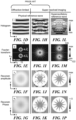
- FIG. 1A A generic, prior art holography apparatus is shown in Fig. 1A in which a field U s ( r ) , scattered by a complex object 10 (the amplitude and phase of which are represented in Figs. 1B and 1C , respectively), is imaged onto a detector plane 12 and superimposed with a known reference field, U r ( r ) , yielding an image-plane hologram, I ( r ) , where r is a vector denoting spatial position.
- Holographic techniques are described generally by Hariharan, Basics of Holography , ⁇ 1.6, (Cambridge UP, 2002), hereinafter, "Hariharan (2002),".
- FT Fourier transform
- the first term is a constant, proportional to the square of the reference amplitude, and may be subtracted or ignored.
- the second, autocorrelation, term is the square of the scattered field and is typically considered negligible with respect to the other terms and may be made so by increasing the amplitude of the reference field.
- a r ⁇ U s ⁇ and conjugate term, A r U s ⁇ ⁇ , proportional, respectively, to the scattered field and its conjugate, are shifted by - k ⁇ and k ⁇ , i.e., they are shifted by 2
- the conjugate of a complex quantity has an imaginary component of equal magnitude and opposite sign.
- Either direct or conjugate image, once filtered, may be referred to herein as an "isolated crossterm.”
- off-axis holography provides a means to determine the complex field, both phase and amplitude, from a single image so long as the field is band-limited.
- the physics of wave propagation guarantees that the scattered field is spatially bandlimited to the Ewald circle of reflection, which is to say that the support of ⁇ s is contained within a circle of radius 2 ⁇ / ⁇ .
- the component of the wavevector of the reference wave in the detector plane may likewise be as large as 2 ⁇ / ⁇ .
- the direct and conjugate terms may always be determined separately by off-axis holography with sufficiently oblique illumination.
- Fig. 1D is a calculated hologram derived using the diffraction-limited optical setup of Fig. 1A , while, in the FT of Fig. 1D shown in Fig. 1E , the direct 14 and conjugate 15 terms have separated into the upper and lower halves of the FT plane and do not appreciably overlap because k ⁇ is of a magnitude larger than the spatial bandwidth (the width of the Fourier distribution of the field).
- the reference wavevector may always be made sufficiently large (to separate the direct and conjugate terms) by oblique incidence of the reference wave, as taught by Leith et al., Reconstructed Wavefronts and Communication Theory, J.Opt. Soc. Am., vol.
- SNOM scanning near-field optical microscopy
- a particularly successful variant of SNOM is the scattering-type SNOM (s-SNOM).
- s-SNOM is described, for example, by Keilmann et al., Near-Field Microscopy by Elastic Light Scattering from a Tip, Phil. Trans. R. Soc. Lond. A, vol. 362, pp. 787-805 (2004 ).
- a sharp local probe is placed near or at the surface of a sample, very often an atomic force microscope (AFM) probe.
- the probe-sample system is illuminated from the far-field.
- the local probe produces a strong local field and acts to couple out the local scattered fields, thus probing the high spatial-frequency near-field.
- the probe is scanned over the surface of the sample and the scattered field intensity is recorded as a function of tip position.
- the resolution in s-SNOM is effectively independent of wavelength and depends only on the tip sharpness.
- Figs. 1H-1K where the situation is simulated in which the diffraction-limited imaging system of Fig. 1A has been replaced by an unspecified superresolved imaging system with a resolution of ⁇ /100, where ⁇ is the wavelength.
- the reference wave U r ( r ) remains the same as used in Fig. 1D-1G , such that the interference fringes (in Fig. 1H ) are necessarily much larger than the smallest features of the sample (shown in Fig. 1B ) that are being imaged.
- the direct and conjugate terms overlap as shown in the FT in Fig 11 , and the reconstruction of both the amplitude (Fig. IJ) and phase (Fig. lK) of the field suffers from serious artifacts.
- SRW synthetic reference wave
- SOH Synthetic Optical Holography
- scattering-type scanning near-field optical microscopy is combined with synthetic reference wave holography to achieve nanoscale infrared images with unprecedented speed and simplicity.
- s-SNOM scattering-type scanning near-field optical microscopy
- a 2.25-megapixel image of nanowire arrays, acquired in less than an hour will be shown as an example of how the present invention may be applied.
- Methods in accordance with the present invention may advantageously shift phase-resolved SNOM from the kilopixel range into the realm of digital cameras. They may also be advantageously applied to many kinds of scanning microscopy, for instance, confocal microscopy, structured illumination, STED, Raman and two-photon scanning microscopy.
- the scattered field is characterized by a frequency that is distinct from any frequency characterizing the illuminating beam
- a reference beam is employed that is coherently converted to the frequency of the scattered field of interest.
- image shall refer to any multidimensional representation, whether in tangible or otherwise perceptible form, or otherwise, whereby a value of some characteristic (amplitude, phase, etc.) is associated with each of a plurality of locations corresponding to dimensional coordinates of an object in physical space, though not necessarily mapped one-to-one thereonto.
- a value of some characteristic amplitude, phase, etc.
- the graphic display of the spatial distribution of some field either scalar or vectorial, such as field intensity or phase, for example, constitutes an image. So, also, does an array of numbers, such as a 3D holographic dataset, in a computer memory or holographic medium.
- imaging refers to the rendering of a stated physical characteristic in terms of one or more images.
- hologram An image (in the generalized sense defined in the preceding paragraph) containing both phase and amplitude information associated with a scattered field may be referred to herein as a "hologram.” It is to be understood that, for further analysis or display of data, not all of the information contained within a hologram must be used.
- object shall refer, interchangeably, to a tangible, non-transitory physical medium or object capable of being rendered as an image, whether in transmission or in scattering.
- the "incident field” shall refer to that field present in the absence of the sample
- the "scattered field” is defined to be the difference between the total field at the detector when the sample is present and the incident field.
- the difference between the total field measured in the vicinity of the sample or in the far field may arise due to elastic or inelastic processes, such as diffraction, scattering, fluorescence, stimulated emission or stimulated emission depletion, etc.
- the field at the sample may be referred to as "the local field.”
- the local field may be reflected, transmitted, or scattered towards the detector, and, in other instances, the local field may be guided to a detector, via a tapered glass fiber, transmission line, or otherwise.
- the field at the detector shall be referred to as "a field associated with the scattered field,” whether the local field propagates to the detector via free space, or whether the field is guided to the detector.
- tip 222 may serve for purposes both of a “local probe” and a “near field probe,”.
- a “near field probe” is merely one form of a local probe, and both terms are now rigorously defined to avoid any misunderstanding:
- a “local probe,” as the term is used herein, shall be defined as a localization of the field used to probe the sample by any means. This includes, for example, a focus, associated with a focal point which is scanned. Such a focus may be formed by refractive, reflective, or diffractive elements.
- the local probe may also be formed by other means of field-localization such as the placement of an aperture in the near-zone of the sample.
- the local probe may generally interrogate a finite volume of the sample but is associated with a point that is scanned.
- a “near field probe,” as used herein, is a local probe that, additionally, consists of a material element which interacts with the sample through the field in the near zone of the sample, that is in the region where evanescent fields are appreciable.
- the near-field probe will usually consist of elements which are of high spatial-frequency, that is, it has features with a local radius of curvature smaller than the wavelength.
- the probe like the local probe of which it is a special case, is associated with a point which is scanned. It may be made of any material, but is commonly metallic, or a semiconductor, or a dielectric.
- the common near-field probe is a sharp needle-like structure with a tip brought into close proximity or even touching the sample.
- ⁇ shall designate the propagation axis where an illuminating beam is incident upon a sample, while x ⁇ and ⁇ shall designate axes transverse to the propagation axis.
- white light position referring to any interferometer, shall denote the point where the phase difference between light traversing both interferometer arms is zero for all wavelengths.
- a source of electromagnetic radiation (also referred to herein as a “source,” or as an “illuminating source”) may be referred to as a “broadband source” when it is characterized by a bandwidth which exceeds the spectral resolution of the detection scheme, in the case of spectrally resolved measurements, or by a bandwidth which exceeds the frequency defined by the inverse of the longest delay introduced in the reference arm.
- sources characterized herein as broadband include thermal radiation sources such as a glow bar, as conventionally employed in Fourier transform infrared (FTIR) spectroscopy, and plasma sources such as a current-induced high-temperature argon arc source, described by Bridges, et al., Characterization of argon arc source in the infrared, Metrologia, vol. 32, pp. 625-628 (1995 ).
- coherent broadband infrared light may be generated by a difference frequency generator (DFG), as described by Amarie et al., Broadband-infrared assessment of phonon resonance in scattering-type near-field microscopy, Phys. Rev. B, vol. 83, 045404, (2011 ).
- DFG difference frequency generator
- sources that emit multiple discrete wavelengths simultaneously include sources that emit multiple discrete wavelengths simultaneously, ⁇ 1 , ⁇ 2 , ..., ⁇ N .
- sources include: frequency comb light sources, lasers emitting multiple-frequency radiation, gas discharge lamps, and emission from a broadband source filtered with a Fabry-Perot resonator.
- monochromatic sources such as quantum cascade lasers or gas lasers, for example, which continuously emit at the same single wavelength.
- monochromatic frequency scanning sources may be employed, emitting radiation at only one single wavelength at a given time. The wavelength may be swept between two defined limits. The wavelength sweeping may be continuous, partially continuous or discrete, manual or automatic. For discrete sweeping, the wavelengths ⁇ 1 , ⁇ 2 , ..., ⁇ N are sequentially emitted.
- monochromatic frequency scanning sources include quantum cascade lasers, gas lasers and other laser types using a motorized grating or rotating mirror to sweep the frequency.
- Methodachromatic frequency scanning sources emit radiation simultaneously at a number M of discrete wavelengths numbered ⁇ 1 , ⁇ 2 , ..., ⁇ M . Each individual wavelength ⁇ m may be swept from wavelength ⁇ m,a to wavelength ⁇ m,b . Sweeping may be discrete, partially continuous or continuous. Sweeping of the wavelength ⁇ m may be independently from the weeping of other wavelengths, or, alternatively, all wavelengths ⁇ m may be swept dependently.
- An example of emission falling within the rubric of a multichromatic frequency scanning source is emission from several monochromatic frequency scanning sources superimposed to form a single output beam, where each source may be swept independently.
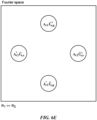
- Figs. 1L-1P illustrate a simulation of superresolved imaging as would apply in a case where an hyperoscillatory reference field were to be available.
- the results of Fourier transforming a hologram obtained using the system of Fig. 1A have been combined with a reference field adequate to separate the field and its conjugate as in Fig. 1E .
- a simulated hologram obtained under these conditions is shown in Fig. 1L .
- the rate of phase variation of the reference field was chosen so that the phase cycles through 2 ⁇ every 4 pixels in the y-direction.
- the reference wavevector is thus a quarter of the total bandwidth of the image and provides minimal overlap (in the Fourier-space transform shown in Fig. 1M ) between the field and its conjugate.
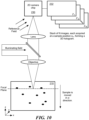
- SRWs Use of SRWs, defined above, is introduced herein as a new concept in holography, as applied to imaging systems that make use of serial data acquisition such as confocal microscopy ( Fig. 2A ) or scanning near-field optical microscopy (SNOM) ( Fig. 2B ), and additional embodiments developed in the course of the following description.
- serial data acquisition such as confocal microscopy ( Fig. 2A ) or scanning near-field optical microscopy (SNOM) ( Fig. 2B ), and additional embodiments developed in the course of the following description.
- the reference field is varied across the image to encode the amplitude and phase of the scattered light.
- the reference field is varied across the image to encode the amplitude and phase of the scattered light.
- the reference field is varied across the image to encode the amplitude and phase of the scattered light.
- Eq. (1) is the generic expression of a synthetic hologram, where U s may be any field scattered or reflected in a scanning microscopy setup. It is identical to a wide-field hologram, from which amplitude and phase of U s may be recovered by standard reconstruction methods.
- the synthetic reference wave (SRW), introduced in accordance with the present invention, solves the fundamental problem of generating hyperoscillatory reference fields, and it also provides a means for readily implementing novel holographic schemes in a number of serial coherent imaging modalities.
- SRW synthetic reference wave
- ⁇ is the optical frequency and c is the velocity of light
- the reference field may be adjusted arbitrarily (in the sense defined above) between measurements so as to achieve any desired spatial dependence.
- the reference field, whose phase and amplitude may, in principle, both be controlled independently of the rest of the experiment, also may be taken to be a function of time U r [r(t)] A r (t)e -i ⁇ r(t) .
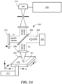
- Fig. 2A depicts salient features of a confocal microscopy system, designated generally by numeral 200.
- a quasi-monochromatic source 202 preferably a single-mode laser in the embodiment shown, emits one or more substantially coherent beams 204 of light.
- Beam 204 may be characterized by a wavelength ⁇ , or by a plurality of wavelengths, such as a comb of wavelengths generated when source 202 operates in a mode-locked modality, for example.
- the interrogating beam may also be a beam of electromagnetic waves of any energy, or an acoustic beam, or a beam of massive particles, as long as a mechanism exists for controlling the phase of the reference beam.
- a source 202 that is pulsed, or that is swept in frequency, is also within the scope of the present invention.
- a scanning near-field optical microscope 220 (described infra, with reference to Fig. 2B ) may also be swept in frequency, within the scope of the present invention.
- time-resolved detection allows for deriving a hologram as a function of wavelength, allowing for far-field spectroscopic imaging, as with quantum cascade lasers in the infrared, for example.
- quantum cascade lasers in the infrared for example.
- Beam 204 is split in a Michelson (or other) interferometric configuration, by means of beamsplitter 206, for example.
- Fig. 2A is only one example of the many configurations that may be practiced within the scope of the present invention.
- a portion of beam 204, denoted sample beam 226 (or, equivalently, illuminating beam 205) impinges onto a sample 210, via illumination optics such as focusing lens 208 such that, where the beam impinges upon the sample, the beam is at, or approaching, a physical focus, thereby concentrating the power in the beam at the sample or at a portion thereof.
- Sample 210 may be any sort of physical medium characterized by an extent in the x ⁇ - ⁇ plane, transverse to the axis of incidence of the sample beam U s .
- Sample 210 may also be referred to herein, interchangeably, as a "physical medium,” or as a “specimen.”
- Sample beam 226 moves sequentially to successive fields of view, designated generally by numeral 201, relative to sample 210, and it is to be understood that it is relative motion between axis ⁇ of sample beam 226 and sample 210 that is important, and either (or both) may be moved, by means of an actuator 211 (shown solely by way of example) within the lab frame, within the context of the present invention.
- numeral 210 may designate, particularly, the sample surface upon which illuminating beam 205 impinges, as required by context.
- a second portion of beam 204 is used to form reference beam U r , the phase of which may be modified by phase modulator 212 (depicted as a translating mirror, by way of example, although any means, such as a spatial light modulator (SLM), etc., is within the scope of the present invention).
- phase modulator 212 depictted as a translating mirror, by way of example, although any means, such as a spatial light modulator (SLM), etc., is within the scope of the present invention.
- Alternative methods for generating the reference beam U r include the use of a separate source that emits coherently with source 202 at either the same frequency or at a different frequency.
- a further method for controlling the phase of the reference beam U r is made available by detuning the emission frequency of the second source with respect to the frequency that is to be detected in the scattered field U s .
- modulation as referring to phase in the context of any sort of interferometric measurement is to be understood as applying either to a reference beam or to a signal beam, or to any combination of the two such that the relative phase between the reference and scattered waves incident upon a detector is varied.
- modulation techniques encompassed within the scope of the present invention are described below.
- Reference beam U r directed via beam splitter 206, onto photodetector (or other appropriate) detector 214 (otherwise referred to herein as a "detector"), having been varied in phase as a function of the position of sample 210 being imaged, may be referred to as the artificial reference field.
- photodetector shall denote any device that generates an electrical signal related to the number (or flux) of photons impinging upon the detector, and is thus sensitive to the square of the amplitude of the incident field.
- processor 230 When the field U s scattered from the sample, or a field with a field scattered from the sample, in the sense defined above, is superimposed with one or more reference beams U r at detector 214, a detector signal derived from detector 214 is processed by processor 230 such that an interferogram is recorded and subsequently processed as described in detail hereinafter.
- Processor 230 may be referred to interchangeably herein as a controller.
- the combination of components used to form an interferogram may be referred to collectively herein as an interferometer, designated generally by numeral 216 (shown in Fig. 2D ).
- Confocal microscopy is a particularly advantageous embodiment of the present invention because the scanning may be performed in three dimensions.
- the added dimensionality makes even more space available in the Fourier domain for the multiplexing of signals, as discussed in further detail below.
- An alternative embodiment of the present invention is a scanning near-field optical microscopy (SNOM) apparatus, designated generally by numeral 220 in Fig. 2B .
- Sub-optical-wavelength-dimensioned local tip 222 (also referred to herein as a "probe tip,” “scanning tip,” “near-field probe,” “local probe,” or “tip,” but see the cautionary note in the following paragraph”) is scanned across sample 210, probing the surface with evanescent waves, with signal beam 226 and scattered field U s coupled in the far field via coupling mirror 224.
- tip 222 may serve for purposes both of a "local probe” and a “near field probe,” these are utterly separate functional concepts and must, under no circumstances, ever be conflated.
- a “near field probe” is merely one form of a local probe, and both terms have been rigorously defined in the Definition section above, which definitions are to apply under all circumstances.
- Scanning tip 222 may be the cantilevered tip of an atomic force microscope (AFM), for example.
- AFM atomic force microscope
- phase modulator 212 depicted, for example, as a moving mirror, generates U r as the artificial reference field.
- an illumination scheme may be employed, where the illuminating beam is s-polarized, i.e., parallel to the long axis of an object being imaged (a nanoantenna in Example I below), and perpendicular to the probing tip 222, in order to ensure an efficient excitation of the imaged object and to avoid a direct excitation of the tip 222.
- a nanoantenna in Example I below a nanoantenna in Example I below
- the remaining near-field signal arises from the interaction of the end of tip with the sample where a highly localized field is generated and it is this signal that is desired for purposes of near-field imaging. This part of the signal is strongly dependent on the height of the tip above the sample.
- demodulation It is typical in SNOM that the signal is obtained by tapping the tip 222 and locking in that tapping or recording harmonics of that tapping. This processing of the signal is referred to herein as "demodulation.” It is the common practice because it separates the signal for the so-called background. In nanoholography, the background is in the low-frequency part of the hologram and so demodulation is not typically necessary. It is possible to directly record the detector signal, reconstruct holograms and apply a method to remove the background in the images. For example, a linear function or any other function from the approach curve may be subtracted to remove the background, and thus demodulation is not the only method to do this. Thus, as should be made abundantly clear, demodulation is not necessary for holographic SNOM, indeed, this may be a particular advantage of SOH in some cases.
- tip 222 taps the surface 210 and background signal is rejected in the signal acquired by demodulation of higher harmonics of the tapping frequency ⁇ .
- tip 222 may oscillate at a frequency, say, in the sub-MHz range, for example (tapping-mode AFM), and by subsequent demodulation of the detector signal at 3 ⁇ .
- SNOM modalities are provided by way of example only, and not by way of limitation of the scope of the present invention.
- the near-field probe (whether a cantilever AFM tip, or any other nanoprobe, moved by any means) may move in a volume above the physical medium being imaged, but the invention does not require that it be so moved.
- Other techniques of volume scanning are discussed below, with reference to Figs. 7A and 7B .
- probe 222 shown in Fig. 2B
- probe 222 used, in this embodiment, as a near-field probe, need not be moved periodically in a dimension transverse to the surface ("tapping mode") in order to reject background signal, since background may be removed by filtration in the Fourier space, or by any method that a practitioner, in exercising design choice, elects to employ.
- slow tip deflection modes such as peak force, and contact modes may be practiced to derive amplitude and phase data in accordance with the present invention, however they are not required to be practiced, and are only mentioned by way of example.
- the SRW of the present invention is introduced with any chosen spatial dependence, by controlling the reference field as a function of time. Included in the possible reference fields is the hyperoscillatory plane wave needed in a superresolved hologram, a nanohologram.
- the FT of the data is as in Eq. (2), and exhibits an effective k ⁇ determined by ⁇ .
- the effective k ⁇ may be made as large as desired, making accessible the hyperoscillatory fields needed in super-resolved imaging and near-field phase-resolved imaging, nanoholography.
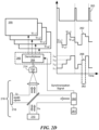
- Illumination source 240 in the embodiment of Fig. 2C , is a source emitting a plurality of wavelengths ⁇ 1 , ⁇ 2 , ..., ⁇ n ,... ⁇ N .
- a SOH method is performed, as described with reference to either of the foregoing Figs. 2A and 2B , and with the flowchart described below with reference to Fig. 3 .
- a dispersive element 242 such as a grating, for example, is disposed before one or more detectors 244 to spectrally analyze the combined field 246 consisting of the reference beam and the scattered field.
- Dispersive element 242 splits the wavelengths ⁇ 1 , ⁇ 2 , ... ⁇ n ,... ⁇ N into several monochromatic beams 247.
- dispersive element 242 may include a prism, or any other dispersive element.
- Detection is performed by an array of one-pixel detectors 244. Each detector (designated by an index #n) detects the beam related to a corresponding wavelength ⁇ n . Recording the n th detected signal 248 as a function of probe position is performed in order to obtain the corresponding n th hologram 255. The recording of all detector signals #1 to #N is performed simultaneously, thus a stack of N holograms is recorded. Each hologram pertains solely a single corresponding wavelength ⁇ n . Processing of each hologram 255 proceeds as described for the SOH method as generally described herein with respect to a single-wavelength source.
- the number of detectors 244 may be greater or fewer than the number N of discrete wavelengths ⁇ i emitted by source 240, although use of fewer detectors results in a loss of information.
- source 240 may be a continuum source, with individual detectors 244 detecting a portion of the spectrum dispersed by dispersive element 242.
- source 240 may include a broadband source, in another embodiment of the invention.
- each one-pixel detector 244 detects a wavelength band [ ⁇ n-1 , ⁇ n+ ⁇ ].
- the n th hologram #n contains amplitude and phase information on the scattered field that is spectrally integrated from ⁇ n- ⁇ to ⁇ n- ⁇ .
- Illumination source 260 is a monochromatic frequency scanning source.
- the SOH method is performed, as described herein with reference to Figs. 2A , 2B , and 3 , as if a single-wavelength source were to be used.
- the method depicted in Fig. 2D is distinct, however, in that source 260 is swept discretely, thus emitting sequentially at wavelengths ⁇ 1 , ⁇ 2 , ..., ⁇ n ,... ⁇ N , as plotted by trace 268 as a function of time.
- the detection is performed with a single-pixel detector 214.
- the local probe 222 (shown in Fig. 2B ) or illuminating beam 205 (shown in Fig. 2A ) is moved to a position on sample 210 in synchrony with synchronization signal 261 and one frequency sweep of the source 260 is executed.
- reference mirror 212 (or any equivalent reference-beam-phase-modulating modality) is fixed.
- the detector signal 262 is recorded during the source sweep.
- a demultiplexer 264 applied to detector signal 262 yields the detector signal I n at wavelength ⁇ n .
- the detector signal I n is stored in the n th hologram 255.
- each hologram 255 contains only a single wavelength ⁇ n .
- Processing of each hologram 255 is performed by the SOH method, as described herein, assuming a single-wavelength source.
- trace 268 of source wavelength as a function of time shows time segments 262 of emission by source 260 at each wavelength to be substantially equal in duration
- embodiments in which wavelength segments are sampled for unequal durations of time are also within the scope of the present invention.
- the reference phase governing, for example, by an offset in the position of mirror 212, may be changed during the course of a frequency sweep of source 260.
- Source 260 may send a synchronization signal 263 when a new sweep is started.
- a further synchronization signal (not shown) may be sent, as well, at each wavelength switch from ⁇ n to ⁇ n+1 .
- These synchronization signals 263 may be used by the device that records the detector signal (SOH controller 265) to achieve the demultiplexing of the detector signal.
- the functionality of a demultiplexer is designated by numeral 264, although it is understood that demultiplexing may be performed by controller 265.
- the synchronization signal may be of either electrical or optical format (such as a TTL signal via cable or optical cable) or, it may involve a change of the source emission ( e.g ,. blanking or attenuation of the source emission during a short time). Synchronization signals are not required, however, in order to implement the methods described with reference to Fig. 2D .
- a synchronization signal 263 may also be issued by the SOH controller, telling the source 260 to (a) start a new sweep, or to (b) switch the wavelength of emission from ⁇ n to ⁇ n+1 .
- a synchronization signal 263 may also be
- parallel multiplexing techniques described with reference to Fig. 2C may be combined with serial multiplexing techniques that have been described with reference to Fig. 2D .
- Spectrally sweeping This method yields N holograms 268 where the wavelengths ⁇ 1,n to ⁇ M,n are encoded in a single hologram, #n. Processing the N holograms yields a total of N ⁇ M amplitude and phase images.
- Variant embodiments employing multiple reference arms, as described with reference to Fig. 6D, for example, are all within the scope of the present invention as claimed.
- the intensity of emission by source 260 may be recorded in parallel with transcription into digital memory of the corresponding hologram 268, as common in instrumentation. This may be accomplished by adding a further detector (not shown) to the setup, or with the same detector 214 used for recording the hologram data. In the latter case, a multiplex approach may be employed for mixing the hologram data with the reference measurement data, thus allowing for demultiplexing after the detector signal has been recorded.
- the instantaneous wavelength of the source emission may be determined independently by an appropriate measurement. For example, this can be accomplished by recording an interferogram of the source emission, either with the interferometer 216 used for recording the hologram or with an additional interferometer setup. For example, the wavelength may be determined with a spectrometer.
- a reference measurement may be obtained by comparing different harmonics of the detector signal.
- the recording of multiple demodulated harmonics is described below with reference to Fig. 7 .
- the desired signal is contained in higher-harmonics n ⁇ with n>1, while harmonics 0 ⁇ and 1 ⁇ mostly contain the background signal. In some circumstances, the latter may be assumed to be spectrally independent and thus serve as a reference for the desired signal at frequency n ⁇ , with n>1.
- a reference measurement may be obtained by comparing the detector signal at the different heights of the local probe.
- the reference measurements may be used for correcting errors of source 210 in tuning to the same wavelength ⁇ n with the same emission intensity in repeated measurements, as in repeated sweeps at different locations on sample 210 of local probe 222 or illuminating beam 205.
- phase function ⁇ r (t) as a function of time t largely considers a linear ramp as a function of time, it is to be understood that such consideration is only by way of example and for heuristic convenience. In point of fact, various functions oftime may be advantageous under different circumstances.
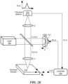
- One specific way to implement a phase function is to describe it as a function of the (x,y) position of the local probe, i.e. , ⁇ r (x,y). In case a piezo-actuated reference mirror 212 is used, for example, this can be accomplished as shown in Fir. 2E.
- any of the modalities such as spectroscopic dispersion of a broadband source after recombination of sample and reference beams, or temporal sweeping of monochromatic or polychromatic sources
- the data are equivalent, and similar approaches may be applied to processing data.
- acquired data may be considered as simply a (Q+1)-dimensional hologram, where the raw data are acquired in a space-frequency domain.
- FT Fourier transform
- the stack of 2D holograms may be merged to a 3D data volume. Processing of the data then is applied to the 3D data volume, rather than to the 2D holograms individually. This transfers the individual 2D SRWs to a single 3D SRW.
- a separation of the direct and conjugate term is possible when the variations in at least one axis are not too rapid.
- scattered field U s may be associated with tip 222 acting as a near-field probe, as defined above.
- ⁇ is typically chosen so that k x ⁇ x ⁇ 2 ⁇ .
- the shift, k ⁇ should be a quarter of the bandwidth in order to maximize separation of the direct and conjugate images while avoiding aliasing. This implies that the phase should complete a 2 ⁇ cycle every 4 pixels.
- the spatial sampling rate of the image is preferably chosen so that the bandwidth of the image (that is, the full-width at half-maximum (FWHM)) is no more than half the total bandwidth available. Regardless of the actual spatial bandwidth of the sample, the effective tip radius ⁇ sets a best-possible resolution and hence limits the bandwidth of the acquired image to 2 ⁇ / ⁇ .
- the hologram By acquiring data at a spatial sampling rate of half the tip radius or finer, the hologram is guaranteed to provide enough bandwidth to separate the direct and conjugate images with an optimum effective k ⁇ .
- the sampling requirement may be relaxed, as may the magnitude of k ⁇ .
- filtering may be applied in order to reduce or eliminate the autocorrelation term.
- An increase in both the sampling rate and k ⁇ provides as large a separation of the desired (direct image) signal from the autocorrelation as may be indicated.
- Phase-resolved SNOM requires that the motion of the mirror be synchronized with the motion of the probe. This then greatly increases cost and complexity.
- the phase is determined at each pixel individually, this has meant that phase-resolved near-field imaging has, to-date, been slower than amplitude-only SNOM and atomic force microscopy, and therefore provides smaller images than the AFM on which it is based. Because only one datum needs to be acquired at each pixel and no synchronization is require between the probe and the reference arm, data may be acquired very fast using nanoholography, in principle as fast as AFM.
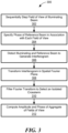
- Steps in accordance with methods of the present invention are depicted, by way of example, in flowchart 300 of Fig. 3 .
- a field of view of one or more quasi-monochromatic beams is sequentially stepped (302) in a transverse plane with respect to propagation axis of the illuminating beams.
- a specified phase is associated (304) with an artificial reference field for each field of view.
- the illuminating and reference beams are combined and detected (306) to generate an interferogram, which is then transformed (308) into a transform plane, and filtered (310) to isolate a crossterm. Transformation of the data takes advantage of mutual information available across pixels.
- Transformation is typically by Fourier transform into a spatial Fourier transform space, however it is to be understood that, within the scope of the present invention, other transforms, including specialized linear and non-linear transforms, may be employed.
- transforms including specialized linear and non-linear transforms, may be employed.
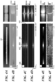
- FIG. 4A shows the IR-gap nanoantenna consisting of two coaligned metal nanorods, each 3.6 um in length and 100 nm win width, that are separated by a 100 nm wide gap.
- a close inspection of the gap region (digital zoom-in shown in the right column of Fig. 4C reveals individual fringes: Lines showing strong contrast (white and black colors) correspond to a constructive interference of the scattered antenna near fields and the reference wave, while the uniform grey-colored lines reflect a destructive interference.
- the s-SNOM employed in this Example is based on an atomic force microscope (AFM) where a dielectric tip acts as a scattering near-field probe 222.
- the tip is scanned over the surface of the sample, and the p-polarized scattered field is recorded as a function of tip position spaced at 10 nm intervals.
- the light scattered out of the tip-sample system was superimposed with a reference field with a linear-in-time phase function.
- the reference phase was controlled to change by 2 ⁇ every 4 steps in the y-direction, as in the simulation shown in Fig. 1(e) , resulting in an SRW that is hyperoscillatory with magnitude of k ⁇ that is 232 times the free-space wavenumber.
- Fig. 4A shows the topography of an IR-gap antenna 401
- Fig. 4B shows a simultaneously acquired hologram of the IR-gap antenna.
- the Fourier Transform (FT) of the hologram is calculated, and depicted in Fig. 4C .
- FIG. 4E shows the resulting amplitude map
- Fig. 4F shows the resulting phase map.
- This field distribution reveals the typical dipolar mode of an optical antenna, characterized by strong field values at the rod extremities known to oscillate out-of-phase by 180°.
- This example clearly reveals the capability of nanoscale-resolved amplitude- and phase-imaging with an artificial reference wave.
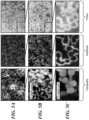
- Fig. 5A depicts an unprecedented 20 ⁇ m ⁇ 20 ⁇ m, 2.25 Megapixel (1500 ⁇ 1500) optical near-field phase and amplitude image, acquired in 55 minutes.
- the sample 210 is a polished cross section of a ZnO nanowire array that shows a characteristic near-field amplitude and phase contrast owing to a radial doping profile. On each nanowire, a ring-like contrast is apparent in both amplitude and phase
- FIG. 5A The topography and optical images in Fig. 5A show the full measured area. To reveal individual wires, an exploded view of the boxed area is shown in Fig. 5B , while another subsequently exploded view is shown in 5C. Note that the exploded views are digital zoom-ins into the data of Fig 5A and were not obtained by rescanning at high-resolution, rather, all displayed data were acquired in a single continuous scan over 55 minutes. A pixel is 13 nm wide, smaller than the tip radius of 20 nm, and, thus, the images are resolution-limited by the radius of the tip rather than sampling rate.
- the images clearly show the ring-like shapes in the amplitude and phase images with a lateral resolution of 13 nm (apparent, for example, in the dark rim between two bright rings in Fig.5C ).
- the ability to record nanoscale-resolved optical images of a width of tens of micrometers allows for an easy and fast identification of single isolated nanowires from the vast number of clustered nanowires.
- Nanoholography makes this emerging technology more broadly accessible by easing implementation, and more practically useful by dramatically reducing imaging time.
- the SRW concept opens new horizons in holography. Holography is no longer constrained to physically realizable reference fields. These ideas may be applied advantageously not only to near-field methods like SNOM where nanoholography is made possible, but also to other scanned imaging techniques including far-field scanning methods like scanning confocal microscopy where the probe position, r ( t ) , is replaced by the position of the focus.
- Nonlinear (in time) reference wave functions may be used to provide a rapidly oscillation reference in select regions of the sample and so acquire high spatial-bandwidth data only where needed, further speeding image acquisition.
- Reconfigurable reference fields may be made into Hadamard masks or random basis functions used to implement compressive holography, recently shown great potential in imaging sparse objects from minimal data sets.
- the reference field may be controlled by feedback from the AFM topography to paint onto the acquired image a linear phase gradient that follows the contours of the sample.
- Specialized SRWs may be tailored to rapidly identify defects and irregularities in manufactured samples.
- Synthetic optical holography may advantageously provide the fastest image acquisition in near-field phase imaging today, improving imaging times by one to two orders of magnitude. While current schemes rely on pixel-by-pixel interferometry, where many data must be acquired for each pixel, in holography the information is distributed (multiplexed) so that only one datum is acquired at each pixel Thus, the speed of imaging in nanoholography is only limited by the mechanical speed of the underlying AFM. Moreover, nanoholography is relatively easy to implement. With constant-velocity scanning and a linear phase ramp in the reference, there is no synchronization required between the reference arm and the probe.
- An error in synchronization between scanning tip position and phase simply amounts to an offset in the origin of time for the phase function, and the additional global phase, may be wrapped into ⁇ 0 .
- the optical system essentially becomes decoupled from the mechanical AFM system, greatly simplifying implementation.
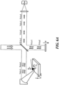
- wavelength multiplexing may be accomplished with a single reference arm, as shown in Fig. 6A , where two frequencies, ⁇ 1 and ⁇ 2 are shown for heuristic convenience, although the extension to n frequencies is evident to a person of ordinary skill in the art.
- a single reference arm displacement produces different phase ramps for the different frequency components of the field, ⁇ 1 and ⁇ 2 .
- a particularly advantageous embodiment may be employed in conjunction with confocal microscopy where the field of view 201 (shown in Fig. 2A ) may be scanned in three dimensions.
- a spatial Fourier transform volume depicted in Fig. 6C , is ample for accommodation of a large number of direct crossterms 630, 634, 636, and 638, and their respect conjugates 632, allowing for their separate filtering and the derivation of distinct amplitude and phase images at multiple wavelengths.
- multiple reference arms designated generally by numerals 650 and 652, each with respective phase modulators 654 and 656, opens up other possibilities.
- Multiplexed signals with a variety of rates of phase variation map to a variety of regions in the Fourier transform domain, designated generally by numeral 620 in Fig. 6C , even for fields at the same frequency, ⁇ .
- the multiplexed waves may be characterized by various features which allow their separation post-hoc. For example, and without limitation, the multiplexed waves may vary in frequency, polarization, time of arrival at the detector, etc. With sufficient separation in the Fourier domain, as shown in Fig. 6E , the complex fields may again be recovered by appropriate filtering.
- the reference field may be split into two orthogonal polarization states, and the phase of two states may be varied at a different rates ⁇ s and ⁇ p .
- the wavevectors k s ⁇ and k p ⁇ are not required to bear any relation to one another within the scope of the present invention.
- Stepping the local probe to a plurality of successive probe positions in three dimensions may be implemented by literally stepping the probe in three dimensions. This means that the probe position is updated and the probe remains stationary at that position during some time. In SNOM, however, local probe 222 is vibrated in height, thus the third dimension is not accessed in a discrete, but rather in a continuous, fashion. This allows for treating this situation as a 2D stepping process for the x,y coordinates and using multiplexing to encode the height variation. Data can be recovered using a time-division demultiplexing approach or a spectral-domain demultiplexing approach, quite similar to methods described above in the context of Spectrally-Resolved SOH. At each voxel, amplitude and phase are obtained.
- This data set can be used for tomographic reconstruction as described in Sun et al., Nanoscale optical tomography using volume-scanning near-field microscopy, Applied Physics Letters, vol. 95, pp. 121108-121108-3, (2009 ).
- SOH may similarly also apply to other methods that use vibration of the local probe, as will be apparent to persons of ordinary skill in the art.
- stepping may be continuous in one, two, or all, dimensions, within the scope of the present invention.
- N is not limited in principle, although data processing constraints require that N be finite.
- Recording the demodulated signals D n as a function of the probe position yields a stack of holograms #0...#N 703.
- vibration of the local probe, at frequency ⁇ , with waveform 708, as described above, and subsequent time-division demultiplexing of the detector signal I (706) yields N holograms 703.
- the time-division demultiplexing is depicted in Fig. 7C , showing sampling at points 707 during the course of each vibration cycle.
- the sampling rate is chosen such that N data points are acquired during time T.
- Each data point #n contains the momentary detector signal I at the time when the data point #n was recorded.
- Storing the data point #n as a function of the probe position produces a hologram #n.
- a stack of hologram #1...#N is obtained.
- Mechanical stepping of the probe is only one way of scanning that may be employed in recording a hologram in accordance with the present invention.
- Other parameters characterizing a physical medium may also be scanned within the scope of the invention.
- Other scanning methods include: (a) scanning a voltage applied across a portion of the sample, (b) scanning the temperature of the sample, (c) scanning any other physical parameter, such as magnetic field, applied to a portion of the sample, or (d) "scanning" the time by monitoring a dynamic process or movement of a developing sample.
- the x- and y-axes of the hologram do not indicate distance, but rather voltage, temperature, time etc. This applies to all SOH methods.
- a “scanning mechanism” shall refer to any one of the physical devices, all known in the art, for imposing the aforesaid variations in the values of physical parameters associated with a sample.
- locus The value of a scanned parameter at any particular step of the scanning process shall be referred to herein as a "locus" (or plural, "loci").
- locus is a dimension of a hologram that need not be physical space but may include such parameters characterizing the sample such as voltage, temperature, etc.
- each applied variation spans a new dimension of the hologram. For example, scanning the local probe in x,y directions and further varying the sample voltage creates a 3-dimensional hologram.
- scanning methods may be applied to other parts of a microscope setup are also within the scope of the present invention.
- scanning may be applied to the source 204 or to modulators introduced in the interferometer 216 (shown in Fig. 2D ).
- multiplexed SOH has been described above in the context of a swept source (with reference to Fig. 2D , for example) and a mechanical vibration of a local probe (described above, with reference to Fig. 7B , which depicts the special example of a near-field probe, not to be mistaken for the general case of a local probe), it is to be understood that other multiplexing modalities of SOH may be practiced without straying from the scope of the present invention as claimed.
- scanning may also be applied to such other quantities as (a) scanning a voltage applied to part of the sample 210 or (b) illuminating the sample 210 with a second source to provoke changes in the sample.
- multiplexing may also be applied to other parts of a microscope setup. For example, multiplexing may be applied to the source or to modulators introduced in the interferometer 216.
- FTIR symmetric Fourier Transform Infrared
- FTIR configuration 800 of Fig. 8 the illuminating and reference beams both fall on the sample 210, and the total field 802 scattered from the sample is collected and measured as a function of reference arm delay.
- intensity may be obtained as a function of frequency.
- This configuration is typically used with sources 240 emitting a plurality of wavelengths. SOH is performed as described in previous descriptions of multi-wavelength operation.
- the frequency information is encoded spatially across the hologram. This is in contradistinction to common FTIR, where the frequency information is temporally encoded by taking an interferogram at each pixel.
- Fig. 8 is compatible with stepping the local probe, the combined beam or the sample, in arbitrary dimensions, i.e., in 1 dimension (line), 2 dimensions (image), or 3 dimensions (volume).
- the scattered field is evaluated for only a single position of the local probe or illuminating beam at a given time.
- the superposition with the reference field is detected by a one-pixel detector.
- This concept can be extended by detecting the scattered field in a spatially-resolved way, described, now, with reference to Fig. 9 .
- one or more illuminating beams may impinge upon the sample 210 and the scattered light U s from one or more positions on the sample may be detected in parallel at a given time.
- an array of one-pixel detectors is used.
- each one-pixel detector is assigned to a specific position on the sample, which can be conveniently done by an imaging system using lenses.
- This extension allows acquisition of data for a single hologram in a parallel fashion.
- the hologram data may be recorded line-wise instead of pixel wise.
- This embodiment of the present invention also advantageously provides for simultaneous acquisition of a plurality of holograms.
- Beam 204 from source 202 is split by beamsplitter 206 into illuminating beam 205 and reference beam U r .
- Beam 204 from source 202 is split by beamsplitter 206 into illuminating beam 205 and reference beam U r .
- scattered beam U s from sample 210 is collected by imaging system 820 and combined with reference beam U r at line camera 824, spatially resolving the x direction.
- a phase function is generated with reference beam U r by employing amplitude or phase modulation.
- the signal of the detectors is recorded as a function of the sample position, thus a line of the hologram is obtained, and a 2D hologram 824 is obtained by line-wise recording the data.
- the hologram 824 may then be processed using SOH techniques elsewhere described herein.
- the reference beam may also be superimposed with the scattered fields at the camera by sending the reference beam through the camera lens, and/or at normal incidence to line camera 822.
- an image camera (two-dimensional) 830 may be employed for generating an interferogram 832 at each of a plurality of positions of sample 210, stepped in the z direction (normal to camera array 830), based on superposition of scattering and reference beams.
- Three-dimensional holograms are obtained by plane-wise recording the interferometric data, and processed as described above. Again, oblique incidence of reference beam U r is not required.
- a contemporaneous data set may be analyzed, and images may be derived on the basis on a partial dataset acquired to an intermediate point in the course of sequential scanning. This allows for a provisional view of analyzed data, while additional data are continuously acquired and aggregated in a larger data set, on the basis of which amplitude and phase images may be recalculated.
- a "two-line" method similar to what is done in phase-stepping homodyne interferometry, may be employed, but the 90-degree phase steps are taken across adjacent lines using the SRW method.
- the first line can be considered to contain the cosine term, the second line the sine term, the third line the -cosine term and so forth, of the complex-valued electric field E s of the sample arm.
- New Line 1 1 * Line 1 + 1 i * Line 2
- New Line 2 1 i * Line 2 ⁇ 1 * Line 3 .
- N-lines can be combined to form one line, as described in phase-stepping homodyne interferometry.
- the autocorrelation term C can be suppressed.
- sets of four pixels may be grouped, assuming the scattered field to be the same at each pixel. Given the values of the SRW, the data may then be fit to a sinusoid. Such an approach is very local and could be implemented fast as data are collected. It can also be implemented with any SRW as long as the SRW varies enough to produce sufficiently linearly independent data. That is, the SRW need not mimic a plane wave. It is, however, also over-constrained, in that it reduces the number of unknowns by a factor of 4. Thus, this approach fails to make use of some of the available information across pixels, so-called mutual information.
- a subset of the data may be treated by the classical FT method. That is, the SRW behaves like a plane-wave over a block of the data and this block of data is treated in the usual way by FT-filter-IFT.
- This allows for a windowed approach to the problem, taking advantage of the mutual information across the block and allowing for adaptive sampling schemes to treat samples that have patches of high variation and low variation. The disadvantage is that this approach ignores available information across blocks.
- the N-pixel data problem can be thought of in a more general setting as a problem of solving for the 2N unknowns that represent the scattered field, with M discrete frequencies, and, without spectrally-resolved detection, this becomes 2MN unknowns from N data.
- the complex scattered field at each frequency may be determined from data at four pixels by assuming the scattered field is the same at all four pixels and then fitting the data to two sinusoids.
- the data consist if N pixels at M frequencies and the result data set of MN data must be used to found the 2MN unknown values of the scattered field.
- this can be accomplished with the usual FT-filter-IFT approach but now in one dimension higher.
- the key point is an assumption that reduced the unknowns by at least a factor of two. This can also be done by taking patches of the data as described above for the single-frequency case.
- Typical piezo stages have a travel range of between several 100s of micrometers to a few millimeters. Particularly for longer wavelengths such as infrared light and THz light, these ranges fall a bit short for generating large k-vectors or for recording holograms with 1000s of lines. This situation is worse if frequency-multiplexing without wrapping, as described herein, is applied. Consequently, it is advantageous to amplify the motion of a single piezo stage-mounted mirror 860 in its effect on the phase by having the beam 861 make multiple passes between mirrors, one a fixed mirror 862, and another piezo-mounted 860.
- Figs. 11A, 11B, and 11C show 1-, 2- and 4-fold increases in the phase modulating effect of motion of piezo-mounted mirror 860.
- a first piezo stage 870 (preferably, with a large travel range) scans a linear ramp.
- the k y vector is generated and, optionally, also phase wrapping.
- a second piezo stage 872 (preferably, with medium travel range and quick response) scans a linear ramp in synchronization with the probe stepping. When the recording of a new line starts, the second piezo stage starts the scan of a linear ramp. The linear ramp is scanned while the line is recorded.
- the resultant reference phase 874 is plotted vs. time in Fig. 11D .
- the first piezo stage mirror 870 need not be synchronized with stepping the local probe 222 or illuminating beam 205, and, moreover, that the function of the two piezo stages 870 and 872 can be achieved with a suitably driven single stage.
- modulation while generally described in the context of varying the relative phase between a field scattered by a sample and a reference beam is not so limited, within the scope of the present invention, and is merely described in those terms for convenience of description and heuristic purposes.
- modulation A variety of means for controlling, and, thus, modulating, the relative amplitude and phase of the reference beam relative to the scattered beam are now described by way of example, and without limitation.
- phase modulation may be deliberately employed for the generation of phase functions, a phase modulation by some of these methods could occur without intention, thus producing unwanted phase shifts in the reconstructed images.
- Such contributions may be corrected for, by, for example, (a) calibration measurements or (b) by taking into account the actual geometry and other factors of the setup to create a correction function.
- the foregoing discussion applies to amplitude modulation and to any other modulation as well.
- phase modulation and other modulation techniques of the reference arm are a fundamental part of SOH. Any errors introduced in the modulation may degrade the performance of SOH, consequently, care must be taken to compensate for errors introduced during the course of phase modulation.
- a piezo stage 870 shown, for example, in Fig. 11C
- a non-zero error (bias) may remain even in the static case.
- FIG. 12 An embodiment of the present invention is now described with reference to Fig. 12 , allowing for the implementation of SOH techniques described herein in confocal microscopes where galvo beam scanners 880 are employed.
- a lens 882 By placing a lens 882 in front of reference mirror 884, light 886 is reflected back in the same angle.
- the reference beam passes through pin hole 888 in front of detector 214 at any angle of the beam scanners 880 (i.e., the reference beam is properly descanned).
- the lens 882 may be replaced by a retroreflector or any other kind of optical component that reflects light back to its source. In this case, a lens is not necessary.
- Lens 882 and mirror 884 are mounted on a linear piezo stage 890 and moved together to generate a phase function.
- Infrared holography where phase contrast in reflection or scattering yields a measure of absorption: It has recently been demonstrated that the phase in a SNOM experiment may be related to the local absorption. Using sources emitting a plurality of wavelengths, swept-sources or broadband sources, complex-valued spectra from the sample may be obtained. The complex-valued spectra not only contain the reflection coefficient, as it would be obtained from a non-interferometric measurement, but also the absorption of the sample. More details on this application may be found in Huth et al., Infrfared-Spectroscopic Nanoimaging with a Thermal Source, Nature Materials, viol. 10, pp. 352-56 (2011 ).
- holograms measured with SOH may be turned into classical viewable holograms. Additionally, raw holograms from experiments involving a plurality of frequencies may be recorded by a processor and turned into classical viewable color holograms by means of a printer. It is, moreover, possible to process SOH holograms, magnifying imaged structures to visible scales.
- THz Holography in Microscopy and Scanning Systems SOH can also be applied to THz frequencies because the key element of SOH is the reflection of light from a mirror which works from visible to THz frequencies, and even x-ray mirrors and radar mirrors are possible. Imaging is difficult in the THz region of the spectrum because camera technology is lacking. This makes the SOH concept attractive for THz because only a one-pixel detector is needed. SOH with THz radiation may enable holographic microscopy at THz, yielding amplitude and phase maps of the sample. Moreover, a 3D THz scanner using SOH techniques may be used in security. A depth range of a few meter can be expected for THz. This makes THz radiations particularly attractive for 3D scanner of large objects such as humans, cars etc.
- Rapid SNOM and Megapixel SNOM In SNOM, amplitude- and phase-resolved measurement of the light that is scattered or collected by tip 222 (shown, for example, in Fig. 2B ) is usually performed with interferometric methods. Among these are homodyne, heterodyne, pseudoheterodyne and phase-shifting. SOH can replace these interferometric methods, thus yielding amplitude- and phase-resolved near-field imaging. The advantage is a gain in speed and simplicity. With SOH, extremely short integration times are possible, enabling pixel rates well above 1 kHz. In comparison to interferometric methods, a factor of >10 in speed can be expected.
- the ability to record more than 1000 pixels per second enables applications such as the acquisition of megapixel near-field images with SNOM in times on the order of minutes or hours. This is useful for screening applications in biomedicine, graphene production, semiconductor fabrication, etc.
- a further application is rapid SNOM where a kilopixel near-field image can be recorded in a time frame on the order of seconds. Acquiring a series of near-field images allows the visualization of dynamic processes.
- Embodiments of the present invention may advantageously be considered as interferometric amplification of scatter signals, potentially by several orders of magnitude, thereby advantageously providing for the measurement and imaging, with substantial signal-to-noise, of weak signals.
- advantage may be provided even with respect to intensity images (squaring amplitude images) with respect to non-holographic modalities.
- certain disclosed methods for nanoholographic imaging may be implemented as a computer program product for use with a computer system.
- Such implementations may include a series of computer instructions fixed either on a tangible medium, such as a computer readable medium (e.g., a diskette, CD-ROM, ROM, or fixed disk) or transmittable to a computer system, via a modem or other interface device, such as a communications adapter connected to a network over a medium.
- the medium may be either a tangible medium (e.g., optical or analog communications lines) or a medium implemented with wireless techniques (e.g., microwave, infrared or other transmission techniques).
- the series of computer instructions embodies all or part of the functionality previously described herein with respect to the system.
- Such computer instructions can be written in a number of programming languages for use with many computer architectures or operating systems. Furthermore, such instructions may be stored in any memory device, such as semiconductor, magnetic, optical or other memory devices, and may be transmitted using any communications technology, such as optical, infrared, microwave, or other transmission technologies. It is expected that such a computer program product may be distributed as a removable medium with accompanying printed or electronic documentation (e.g., shrink wrapped software), preloaded with a computer system (e.g., on system ROM or fixed disk), or distributed from a server or electronic bulletin board over the network (e.g., the Internet or World Wide Web). Of course, some embodiments of the invention may be implemented as a combination of both software (e.g., a computer program product) and hardware. Still other embodiments of the invention are implemented as entirely hardware, or entirely software (e.g., a computer program product).
- a scanning near-field probe may be served by a nanoparticle inserted into the sample and driven, for instance by a magnetic field, or allowed to drift by Brownian motion or some other diffusive process.
- An appropriately fast-rising phase ramp of the reference may then be used with assumptions about the particle path to a 1-D hologram of the field scattered by the particle-sample system as the particle moves.
- illuminating beam or reference beam may propagate as a free-space-propagating beam or as a guided beam.
Landscapes
- Physics & Mathematics (AREA)
- General Physics & Mathematics (AREA)
- Chemical & Material Sciences (AREA)
- Analytical Chemistry (AREA)
- Optics & Photonics (AREA)
- Engineering & Computer Science (AREA)
- Computing Systems (AREA)
- Theoretical Computer Science (AREA)
- Holo Graphy (AREA)
- Investigating Or Analysing Materials By Optical Means (AREA)
Claims (17)
- Procédé permettant de générer un hologramme caractérisant un champ diffracté émanant d'un échantillon, le procédé comprenant :la fourniture d'un faisceau lumineux (204) ;le balayage séquentiel d'une position d'une sonde par rapport à l'échantillon (210), dans lequel la sonde comprend un foyer du faisceau lumineux (205) adapté pour illuminer l'échantillon (210) ou une pointe de sonde (222) illuminée par le faisceau lumineux (205) ;la génération d'un faisceau de référence (Ur) à partir du faisceau lumineux (204) par un séparateur de faisceau et l'imposition d'une fonction de phase spécifiée sur le faisceau de référence (Ur) comme une fonction de temps par rapport à une position de balayage de la sonde pendant un déroulement du balayage séquentiel, dans lequel la fonction de phase est quasi-constante au cours du balayage de chaque position ;la superposition au faisceau de référence (Ur) d'un champ associé à un champ diffracté par l'échantillon (Us) ;la détection du faisceau de référence superposé et du champ associé au champ diffracté par l'échantillon pour chaque position afin de produire un signal détecté ; etl'enregistrement du signal détecté comme une fonction de position afin d'obtenir un hologramme, comprenant en outre le traitement de l'hologramme pour générer une image d'au moins l'une parmi la phase et l'amplitude associées au champ diffracté.
- Procédé selon la revendication 1,
dans lequel le traitement de l'hologramme comprend :la transformation de l'hologramme en un espace de transformation ;le filtrage de la transformation pour isoler un terme croisé unique ; etla retransformation du terme croisé unique pour générer une image d'au moins l'une parmi la phase et l'amplitude associées au champ diffracté. - Procédé selon la revendication 1, dans lequel le balayage d'une position de la sonde par rapport à l'échantillon (210) comporte le balayage de l'échantillon en trois dimensions, dans lequel, lorsque la sonde est la pointe de sonde, ladite pointe de sonde (222) est éventuellement une sonde de champ proche et éventuellement une pointe en porte-à-faux d'un microscope à force atomique.
- Procédé selon la revendication 1, dans lequel le balayage séquentiel d'une position de la sonde (222) par rapport à l'échantillon (210) comporte le passage du faisceau lumineux à une pluralité de positions à des champs de vision successifs, chaque champ de vision englobant une partie de l'échantillon (210), ou le balayage séquentiel de la sonde à une pluralité de positions à des champs de vision successifs du faisceau lumineux, chaque champ de vision englobant une partie de l'échantillon.
- Procédé selon la revendication 1, dans lequel au moins l'un parmi le faisceau lumineux (204) et le faisceau de référence (Ur) est quasi-monochromatique.
- Procédé selon la revendication 1, dans lequel au moins l'un parmi le faisceau lumineux (204) et le faisceau de référence (Ur) comporte une pluralité de longueurs d'onde et éventuellement une pluralité de longueurs d'onde distinctes.
- Procédé selon la revendication 1, comprenant en outre le balayage d'une longueur d'onde caractérisant le faisceau lumineux (204).
- Procédé selon la revendication 7, comprenant en outre :la résolution en longueur d'onde du faisceau de référence superposé (Ur) et du champ associé au champ diffracté pour chaque position afin de produire une pluralité de signaux de détecteur ; etl'enregistrement du signal détecté comme une fonction de position afin d'obtenir un hologramme pour chacun de la pluralité de signaux de détecteur.
- Procédé selon la revendication 3,
dans lequel la pointe de sonde (222) est une sonde locale et dans lequel le balayage par rapport à l'échantillon est réalisé par la vibration d'une pointe locale de la sonde locale à une fréquence fondamentale, comprenant éventuellement en outre la démodulation simultanée des signaux de détecteur à des harmoniques de la fréquence fondamentale. - Appareil selon la revendication 2,
dans lequel le terme croisé est l'un parmi un terme direct et un terme conjugué dans une transformée de Fourier de l'hologramme. - Procédé selon la revendication 1, dans lequel l'imposition d'une fonction de phase spécifiée à un faisceau de référence (Ur) par rapport à la position de balayage de la sonde comporte la modulation d'une phase caractérisant le faisceau de référence (Ur), éventuellement par une modulation de phase du champ de référence par réflexion sur un miroir mobile.
- Procédé selon la revendication 1, dans lequel l'imposition d'une fonction de phase spécifiée à un faisceau de référence (Ur) par rapport à la position de balayage de la sonde comporte l'incrémentation d'une phase caractérisant le faisceau de référence comme une fonction linéaire du temps, éventuellement l'enveloppement de la phase modulo 2π.
- Procédé selon la revendication 1, dans lequel le faisceau lumineux comporte un faisceau de photons, et éventuellement dans lequel au moins l'un parmi le faisceau lumineux et le faisceau de référence :se propage dans l'espace libre ; oucomprend une onde guidée.
- Appareil permettant l'imagerie d'au moins l'une parmi une phase et une amplitude caractérisant un champ diffracté émanant d'un échantillon, l'appareil comprenant :une source (202) permettant la génération d'un faisceau lumineux (204, 208), la source (202) émettant éventuellement plusieurs longueurs d'onde, de manière séquentielle et/ou simultanée ;un mécanisme de balayage permettant le balayage séquentiel d'une position d'une sonde par rapport à l'échantillon (210), dans lequel la sonde comprend un foyer du faisceau lumineux (205) étant adapté pour illuminer l'échantillon (210) ou une pointe de sonde (222) illuminée par le faisceau lumineux (205) ;un modulateur de phase (212) permettant l'imposition d'une fonction de phase spécifique à un faisceau de référence (Ur), généré à partir du faisceau lumineux par un séparateur de faisceau, comme une fonction de temps par rapport à une position de balayage de la sonde pendant le déroulement d'un balayage séquentiel, dans lequel la fonction de phase est quasi-constante au cours du balayage de chaque position ;un détecteur (214) permettant la détection du faisceau de référence superposé (Ur) et d'un champ associé à un champ diffracté par l'échantillon (Us) pour générer un signal de détecteur, le signal de détecteur étant enregistré comme une fonction de position afin d'obtenir un hologramme ; etun processeur (230) permettant le traitement de l'hologramme pour générer une image d'au moins l'une parmi la phase et l'amplitude associées au champ diffracté par l'échantillon (Us).
- Appareil selon la revendication 14,
dans lequel le mécanisme de balayage est au moins l'un parmi une sonde locale à balayage, une sonde de champ proche à balayage, une pointe en porte-à-faux d'un microscope à force atomique. - Appareil selon la revendication 14,
comprenant en outre un élément dispersif permettant de résoudre les composantes de longueur d'onde avant la détection. - Appareil selon la revendication 14,
dans lequel la source (202) est configurée pour émettre plusieurs longueurs d'onde, de manière séquentielle et/ou simultanée.
Applications Claiming Priority (2)
| Application Number | Priority Date | Filing Date | Title |
|---|---|---|---|
| US201261705296P | 2012-09-25 | 2012-09-25 | |
| PCT/US2013/030411 WO2014051680A1 (fr) | 2012-09-25 | 2013-03-12 | Holographie optique synthétique |
Publications (4)
| Publication Number | Publication Date |
|---|---|
| EP2951647A1 EP2951647A1 (fr) | 2015-12-09 |
| EP2951647A4 EP2951647A4 (fr) | 2016-10-19 |
| EP2951647B1 true EP2951647B1 (fr) | 2025-06-18 |
| EP2951647C0 EP2951647C0 (fr) | 2025-06-18 |
Family
ID=50388839
Family Applications (1)
| Application Number | Title | Priority Date | Filing Date |
|---|---|---|---|
| EP13841978.3A Active EP2951647B1 (fr) | 2012-09-25 | 2013-03-12 | Holographie optique synthétique |
Country Status (3)
| Country | Link |
|---|---|
| US (1) | US9213313B2 (fr) |
| EP (1) | EP2951647B1 (fr) |
| WO (1) | WO2014051680A1 (fr) |
Families Citing this family (31)
| Publication number | Priority date | Publication date | Assignee | Title |
|---|---|---|---|---|
| JP2014082541A (ja) * | 2012-10-12 | 2014-05-08 | National Institute Of Information & Communication Technology | 互いに類似した情報を含む複数画像のデータサイズを低減する方法、プログラムおよび装置 |
| US9658247B2 (en) | 2013-03-15 | 2017-05-23 | Anasys Instruments | Method and apparatus for infrared scattering scanning near-field optical microscopy with high speed point spectroscopy |
| US10117583B2 (en) | 2014-10-22 | 2018-11-06 | illumiSonics, Inc. | Photoacoustic remote sensing (PARS) |
| JP6630120B2 (ja) | 2015-11-06 | 2020-01-15 | 浜松ホトニクス株式会社 | 画像取得装置、画像取得方法、及び空間光変調ユニット |
| US10228389B2 (en) | 2015-12-02 | 2019-03-12 | Bruker Nano, Inc. | Method and apparatus for infrared scattering scanning near-field optical microscopy with background suppression |
| US10327646B2 (en) | 2016-02-02 | 2019-06-25 | Illumisonics Inc. | Non-interferometric photoacoustic remote sensing (NI-PARS) |
| GB2547929B (en) * | 2016-03-03 | 2018-02-21 | Daqri Holographics Ltd | Display system |
| US10241131B2 (en) * | 2016-08-28 | 2019-03-26 | Bruker Nano, Inc. | Method and apparatus for chemical and optical imaging with a broadband source |
| JP6803196B2 (ja) * | 2016-10-27 | 2020-12-23 | オリンパス株式会社 | 顕微鏡装置 |
| US10627338B2 (en) | 2017-03-23 | 2020-04-21 | Illumisonics Inc. | Camera-based photoacoustic remote sensing (C-PARS) |
| EP3382467B1 (fr) * | 2017-03-27 | 2025-06-18 | IMEC vzw | Dispositif, système et procédé d'imagerie holographique |
| WO2018194985A1 (fr) * | 2017-04-19 | 2018-10-25 | Drs Network & Imaging Systems, Llc | Imageur hyper-spectral actif |
| US10416609B1 (en) * | 2018-03-07 | 2019-09-17 | The Government Of The United States Of America As Represented By The Secretary Of The Air Force | Single shot imaging using digital holography receiver |
| US10778912B2 (en) * | 2018-03-31 | 2020-09-15 | Open Water Internet Inc. | System and device for optical transformation |
| JP2022524857A (ja) | 2019-03-15 | 2022-05-10 | イルミソニックス インコーポレイテッド | 単一光源光音響リモートセンシング(ss-pars) |
| CN110297418B (zh) * | 2019-07-11 | 2020-08-25 | 中国地质大学(北京) | 一种基于太赫兹衍射图分解的太赫兹波数字全息成像方法 |
| KR102798792B1 (ko) * | 2019-12-02 | 2025-04-22 | 삼성전자주식회사 | Cdi 기반 검사 장치 및 방법 |
| CA3161943A1 (fr) | 2019-12-19 | 2021-06-24 | Parsin Haji Reza | Detection photoacoustique a distance (pars) et procedes d'utilisation associes |
| US11122978B1 (en) | 2020-06-18 | 2021-09-21 | Illumisonics Inc. | PARS imaging methods |
| US11786128B2 (en) | 2020-06-18 | 2023-10-17 | Illumisonics Inc. | PARS imaging methods |
| EP3922977B1 (fr) * | 2020-06-08 | 2024-08-07 | Universität für Bodenkultur Wien | Procédé pour déterminer une propriété d'une particule dans un milieu |
| EP3940393B1 (fr) | 2020-07-17 | 2026-02-11 | attocube systems GmbH | Procédé pour référencer une mesure de champ proche avec correction de dérive et de fluctuation |
| CN111984209B (zh) * | 2020-09-02 | 2023-01-20 | 暨南大学 | 可显示双套彩色打印和全息图像的超构表面及其设计方法 |
| TR202020477A2 (tr) * | 2020-12-14 | 2021-01-21 | Dokuz Eyluel Ueniversitesi Rektoerluegue | Akusti̇k modül i̇çeren bi̇r di̇ji̇tal hologram görüntüleme ci̇hazi |
| CN112729555B (zh) * | 2020-12-18 | 2022-03-25 | 中国科学院合肥物质科学研究院 | 标准温度法和相对谱线法同步诊断等离子体温度场的方法 |
| CN113156792B (zh) * | 2021-02-09 | 2022-03-18 | 北京理工大学 | 基于级联超颖表面的平移全息复用方法 |
| US11860087B2 (en) * | 2021-04-02 | 2024-01-02 | The Board Of Trustees Of The University Of Illinois | Method and apparatus for nanoscale infrared absorption tomography |
| CN113093499B (zh) * | 2021-04-15 | 2022-03-01 | 中国地质大学(北京) | 一种离散孔径内推的太赫兹数字全息成像方法和系统 |
| CN113203687B (zh) * | 2021-04-29 | 2023-09-08 | 深圳大学 | 一种基于复合相位超构表面的多维度成像方法及装置 |
| US20260044030A1 (en) * | 2022-06-06 | 2026-02-12 | The Board Of Trustees Of The Leland Stanford Junior University | Multi-dimensional convolution operation enabled by photonic frequency synthetic dimensions |
| EP4662479A1 (fr) | 2023-02-08 | 2025-12-17 | Illumisonics Inc. | Système de détection à distance d'absorption de photons pour évaluation histologique de tissus |
Family Cites Families (18)
| Publication number | Priority date | Publication date | Assignee | Title |
|---|---|---|---|---|
| US3640598A (en) | 1967-08-23 | 1972-02-08 | Holotron Corp | Technique of holography by source scanning |
| US3856986A (en) | 1968-12-06 | 1974-12-24 | American Express Invest | Scanned holography systems using temporal modulation |
| US3760344A (en) | 1971-07-28 | 1973-09-18 | Battelle Development Corp | Scanned holography with a rotating extended source |
| US3889226A (en) | 1971-07-28 | 1975-06-10 | Battelle Development Corp | Scanned holography by sector scanning |
| AU4177397A (en) * | 1997-09-03 | 1999-03-22 | Environmental Research Institute Of Michigan | System and method for three-dimensional imaging |
| US6262818B1 (en) * | 1998-10-07 | 2001-07-17 | Institute Of Applied Optics, Swiss Federal Institute Of Technology | Method for simultaneous amplitude and quantitative phase contrast imaging by numerical reconstruction of digital holograms |
| GB0022503D0 (en) | 2000-09-13 | 2000-11-01 | Univ Northumbria Newcastle | Microwve holographic measuring method and apparatus |
| US7221760B2 (en) * | 2001-03-30 | 2007-05-22 | The University Of Connecticut | Information security using digital holography |
| US7359065B2 (en) * | 2005-07-14 | 2008-04-15 | Coherix, Inc. | Method of combining holograms |
| US7602501B2 (en) * | 2006-07-10 | 2009-10-13 | The Board Of Trustees Of The University Of Illinois | Interferometric synthetic aperture microscopy |
| US8331019B2 (en) | 2007-01-26 | 2012-12-11 | New York University | Holographic microscopy of holographically trapped three-dimensional nanorod structures |
| US7978343B2 (en) | 2008-03-21 | 2011-07-12 | The Board Of Trustees Of The University Of Illinois | Nanoscale optical tomography based on volume-scanning near-field microscopy |
| KR101125842B1 (ko) * | 2010-02-26 | 2012-03-28 | 지니포토닉스(주) | 3파장 디지털 홀로그래픽 현미경의 자료처리 방법 |
| CN201804207U (zh) * | 2010-04-23 | 2011-04-20 | 张瑞聪 | 多彩全像的影像合成设备的光偏移补偿装置 |
| WO2011149405A1 (fr) | 2010-05-24 | 2011-12-01 | Phase Holographic Imaging Phi Ab | Microscopie holographique numérique d'objets biologiques translucides |
| JP5358530B2 (ja) | 2010-07-28 | 2013-12-04 | 日立コンシューマエレクトロニクス株式会社 | 光情報記録再生装置及び再生装置 |
| US8976433B2 (en) * | 2010-12-17 | 2015-03-10 | Canon Kabushiki Kaisha | Apparatus and method for irradiating a scattering medium |
| EP2565725B1 (fr) * | 2011-09-02 | 2014-04-30 | Mitutoyo Corporation | Methode et appareil pour la reconstruction exacte de l'onde d'objet en holographie numérique hors axe |
-
2013
- 2013-03-12 EP EP13841978.3A patent/EP2951647B1/fr active Active
- 2013-03-12 WO PCT/US2013/030411 patent/WO2014051680A1/fr not_active Ceased
- 2013-03-12 US US14/389,921 patent/US9213313B2/en active Active
Non-Patent Citations (1)
| Title |
|---|
| RENÉ DÄNDLIKER ET AL: "Measuring optical phase singularities at subwavelength resolution; Measuring optical phase singularities at subwavelength resolution", JOURNAL OF OPTICS. A, PURE AND APPLIED OPTICS, INSTITUTE OF PHYSICS PUBLISHING, BRISTOL, GB, vol. 6, no. 5, 1 May 2004 (2004-05-01), pages S189 - S196, XP020081431, ISSN: 1464-4258, DOI: 10.1088/1464-4258/6/5/009 * |
Also Published As
| Publication number | Publication date |
|---|---|
| EP2951647A1 (fr) | 2015-12-09 |
| US20150077819A1 (en) | 2015-03-19 |
| EP2951647A4 (fr) | 2016-10-19 |
| US9213313B2 (en) | 2015-12-15 |
| WO2014051680A1 (fr) | 2014-04-03 |
| EP2951647C0 (fr) | 2025-06-18 |
Similar Documents
| Publication | Publication Date | Title |
|---|---|---|
| US9213313B2 (en) | Synthetic optical holography | |
| Wu et al. | Imaging biological tissue with high-throughput single-pixel compressive holography | |
| Chen et al. | Superoscillation: from physics to optical applications | |
| US7978346B1 (en) | Methods and systems for realizing high resolution three-dimensional optical imaging | |
| Takeda | Fourier fringe analysis and its application to metrology of extreme physical phenomena: a review | |
| US8558998B2 (en) | Fourier domain sensing | |
| US20170023472A1 (en) | Apparatus and method for quantitive phase tomography through linear scanning with coherent and non-coherent detection | |
| US20130070251A1 (en) | Systems and Methods of Dual-Plane Digital Holographic Microscopy | |
| Park et al. | Low-coherence optical diffraction tomography using a ferroelectric liquid crystal spatial light modulator | |
| Morrill et al. | Measuring subwavelength spatial coherence with plasmonic interferometry | |
| Naik et al. | Coherence holography by achromatic 3-D field correlation of generic thermal light with an imaging Sagnac shearing interferometer | |
| Brooks et al. | Temporal and spectral multiplexing for EUV multibeam ptychography with a high harmonic light source | |
| Ma et al. | Resolution enhancement in digital holographic microscopy with structured illumination | |
| Kashter et al. | Sparse synthetic aperture with Fresnel elements (S-SAFE) using digital incoherent holograms | |
| Joseph et al. | Improving the space-bandwidth product of structured illumination microscopy using a transillumination configuration | |
| Kurekci et al. | Single-pixel multimode fiber spectrometer via wavefront shaping | |
| Taddese et al. | Jones tomographic diffractive microscopy with a polarized array sensor | |
| Tenner et al. | Fourier transform holography with extended references using a coherent ultra-broadband light source | |
| Petrov et al. | Ghost imaging with auxiliary multiplex channels: a review of the latest results | |
| Jordan et al. | Superoscillations and physical applications | |
| Psota et al. | Image plane digital holographic microscope for the inspection of ferroelectric single crystals | |
| Daixuan et al. | Imaging biological tissue with high-throughput single-pixel compressive holography | |
| Petrov et al. | Reconstruction enhancement of noisy data in terahertz pulse time-domain holography by iterative procedure | |
| Machikhin et al. | Single-shot multi-spectral digital holographic imaging through acousto-optic wavelength scanning | |
| Amann et al. | Three-dimensional hyperspectral imaging with optical microcombs |
Legal Events
| Date | Code | Title | Description |
|---|---|---|---|
| PUAI | Public reference made under article 153(3) epc to a published international application that has entered the european phase |
Free format text: ORIGINAL CODE: 0009012 |
|
| 17P | Request for examination filed |
Effective date: 20150730 |
|
| AK | Designated contracting states |
Kind code of ref document: A1 Designated state(s): AL AT BE BG CH CY CZ DE DK EE ES FI FR GB GR HR HU IE IS IT LI LT LU LV MC MK MT NL NO PL PT RO RS SE SI SK SM TR |
|
| AX | Request for extension of the european patent |
Extension state: BA ME |
|
| DAX | Request for extension of the european patent (deleted) | ||
| A4 | Supplementary search report drawn up and despatched |
Effective date: 20160916 |
|
| RIC1 | Information provided on ipc code assigned before grant |
Ipc: G03H 1/04 20060101AFI20160912BHEP Ipc: G01Q 60/18 20100101ALI20160912BHEP Ipc: G03H 1/08 20060101ALI20160912BHEP |
|
| STAA | Information on the status of an ep patent application or granted ep patent |
Free format text: STATUS: EXAMINATION IS IN PROGRESS |
|
| 17Q | First examination report despatched |
Effective date: 20191014 |
|
| REG | Reference to a national code |
Ref country code: DE Ref legal event code: R079 Free format text: PREVIOUS MAIN CLASS: G03H0001040000 Ipc: G03H0001140000 Ref document number: 602013086837 Country of ref document: DE |
|
| RIC1 | Information provided on ipc code assigned before grant |
Ipc: G03H 5/00 20060101ALI20230221BHEP Ipc: G02B 21/00 20060101ALI20230221BHEP Ipc: G03H 1/04 20060101ALI20230221BHEP Ipc: G03H 1/26 20060101ALI20230221BHEP Ipc: G03H 1/00 20060101ALI20230221BHEP Ipc: G03H 1/14 20060101AFI20230221BHEP |
|
| GRAP | Despatch of communication of intention to grant a patent |
Free format text: ORIGINAL CODE: EPIDOSNIGR1 |
|
| STAA | Information on the status of an ep patent application or granted ep patent |
Free format text: STATUS: GRANT OF PATENT IS INTENDED |
|
| INTG | Intention to grant announced |
Effective date: 20250120 |
|
| GRAS | Grant fee paid |
Free format text: ORIGINAL CODE: EPIDOSNIGR3 |
|
| GRAA | (expected) grant |
Free format text: ORIGINAL CODE: 0009210 |
|
| STAA | Information on the status of an ep patent application or granted ep patent |
Free format text: STATUS: THE PATENT HAS BEEN GRANTED |
|
| AK | Designated contracting states |
Kind code of ref document: B1 Designated state(s): AL AT BE BG CH CY CZ DE DK EE ES FI FR GB GR HR HU IE IS IT LI LT LU LV MC MK MT NL NO PL PT RO RS SE SI SK SM TR |
|
| REG | Reference to a national code |
Ref country code: GB Ref legal event code: FG4D |
|
| REG | Reference to a national code |
Ref country code: CH Ref legal event code: EP |
|
| REG | Reference to a national code |
Ref country code: DE Ref legal event code: R096 Ref document number: 602013086837 Country of ref document: DE |
|
| REG | Reference to a national code |
Ref country code: CH Ref legal event code: EP |
|
| REG | Reference to a national code |
Ref country code: IE Ref legal event code: FG4D |
|
| U01 | Request for unitary effect filed |
Effective date: 20250709 |
|
| U07 | Unitary effect registered |
Designated state(s): AT BE BG DE DK EE FI FR IT LT LU LV MT NL PT RO SE SI Effective date: 20250715 |
|
| PG25 | Lapsed in a contracting state [announced via postgrant information from national office to epo] |
Ref country code: GR Free format text: LAPSE BECAUSE OF FAILURE TO SUBMIT A TRANSLATION OF THE DESCRIPTION OR TO PAY THE FEE WITHIN THE PRESCRIBED TIME-LIMIT Effective date: 20250919 Ref country code: NO Free format text: LAPSE BECAUSE OF FAILURE TO SUBMIT A TRANSLATION OF THE DESCRIPTION OR TO PAY THE FEE WITHIN THE PRESCRIBED TIME-LIMIT Effective date: 20250918 |
|
| PG25 | Lapsed in a contracting state [announced via postgrant information from national office to epo] |
Ref country code: HR Free format text: LAPSE BECAUSE OF FAILURE TO SUBMIT A TRANSLATION OF THE DESCRIPTION OR TO PAY THE FEE WITHIN THE PRESCRIBED TIME-LIMIT Effective date: 20250618 |
|
| PG25 | Lapsed in a contracting state [announced via postgrant information from national office to epo] |
Ref country code: RS Free format text: LAPSE BECAUSE OF FAILURE TO SUBMIT A TRANSLATION OF THE DESCRIPTION OR TO PAY THE FEE WITHIN THE PRESCRIBED TIME-LIMIT Effective date: 20250918 |
|
| PG25 | Lapsed in a contracting state [announced via postgrant information from national office to epo] |
Ref country code: IS Free format text: LAPSE BECAUSE OF FAILURE TO SUBMIT A TRANSLATION OF THE DESCRIPTION OR TO PAY THE FEE WITHIN THE PRESCRIBED TIME-LIMIT Effective date: 20251018 |
|
| PG25 | Lapsed in a contracting state [announced via postgrant information from national office to epo] |
Ref country code: SM Free format text: LAPSE BECAUSE OF FAILURE TO SUBMIT A TRANSLATION OF THE DESCRIPTION OR TO PAY THE FEE WITHIN THE PRESCRIBED TIME-LIMIT Effective date: 20250618 |
|
| PG25 | Lapsed in a contracting state [announced via postgrant information from national office to epo] |
Ref country code: CZ Free format text: LAPSE BECAUSE OF FAILURE TO SUBMIT A TRANSLATION OF THE DESCRIPTION OR TO PAY THE FEE WITHIN THE PRESCRIBED TIME-LIMIT Effective date: 20250618 |
|
| PG25 | Lapsed in a contracting state [announced via postgrant information from national office to epo] |
Ref country code: PL Free format text: LAPSE BECAUSE OF FAILURE TO SUBMIT A TRANSLATION OF THE DESCRIPTION OR TO PAY THE FEE WITHIN THE PRESCRIBED TIME-LIMIT Effective date: 20250618 |
|
| PG25 | Lapsed in a contracting state [announced via postgrant information from national office to epo] |
Ref country code: SK Free format text: LAPSE BECAUSE OF FAILURE TO SUBMIT A TRANSLATION OF THE DESCRIPTION OR TO PAY THE FEE WITHIN THE PRESCRIBED TIME-LIMIT Effective date: 20250618 |
|
| PG25 | Lapsed in a contracting state [announced via postgrant information from national office to epo] |
Ref country code: ES Free format text: LAPSE BECAUSE OF FAILURE TO SUBMIT A TRANSLATION OF THE DESCRIPTION OR TO PAY THE FEE WITHIN THE PRESCRIBED TIME-LIMIT Effective date: 20250618 |
|
| PGFP | Annual fee paid to national office [announced via postgrant information from national office to epo] |
Ref country code: GB Payment date: 20260327 Year of fee payment: 14 |
|
| PLBE | No opposition filed within time limit |
Free format text: ORIGINAL CODE: 0009261 |
|
| STAA | Information on the status of an ep patent application or granted ep patent |
Free format text: STATUS: NO OPPOSITION FILED WITHIN TIME LIMIT |
|
| REG | Reference to a national code |
Ref country code: CH Ref legal event code: L10 Free format text: ST27 STATUS EVENT CODE: U-0-0-L10-L00 (AS PROVIDED BY THE NATIONAL OFFICE) Effective date: 20260430 |
|
| U20 | Renewal fee for the european patent with unitary effect paid |
Year of fee payment: 14 Effective date: 20260327 |