EP2951833B1 - Programmierung von bipolarem widerstandsspeicher - Google Patents
Programmierung von bipolarem widerstandsspeicher Download PDFInfo
- Publication number
- EP2951833B1 EP2951833B1 EP14702536.5A EP14702536A EP2951833B1 EP 2951833 B1 EP2951833 B1 EP 2951833B1 EP 14702536 A EP14702536 A EP 14702536A EP 2951833 B1 EP2951833 B1 EP 2951833B1
- Authority
- EP
- European Patent Office
- Prior art keywords
- state
- memory device
- programming
- memory
- electrode
- Prior art date
- Legal status (The legal status is an assumption and is not a legal conclusion. Google has not performed a legal analysis and makes no representation as to the accuracy of the status listed.)
- Not-in-force
Links
Images


Classifications
-
- G—PHYSICS
- G11—INFORMATION STORAGE
- G11C—STATIC STORES
- G11C13/00—Digital stores characterised by the use of storage elements not covered by groups G11C11/00, G11C23/00, or G11C25/00
- G11C13/0002—Digital stores characterised by the use of storage elements not covered by groups G11C11/00, G11C23/00, or G11C25/00 using resistive RAM [RRAM] elements
- G11C13/0021—Auxiliary circuits
- G11C13/0069—Writing or programming circuits or methods
-
- G—PHYSICS
- G11—INFORMATION STORAGE
- G11C—STATIC STORES
- G11C13/00—Digital stores characterised by the use of storage elements not covered by groups G11C11/00, G11C23/00, or G11C25/00
- G11C13/0002—Digital stores characterised by the use of storage elements not covered by groups G11C11/00, G11C23/00, or G11C25/00 using resistive RAM [RRAM] elements
- G11C13/0007—Digital stores characterised by the use of storage elements not covered by groups G11C11/00, G11C23/00, or G11C25/00 using resistive RAM [RRAM] elements comprising metal oxide memory material, e.g. perovskites
-
- G—PHYSICS
- G11—INFORMATION STORAGE
- G11C—STATIC STORES
- G11C13/00—Digital stores characterised by the use of storage elements not covered by groups G11C11/00, G11C23/00, or G11C25/00
- G11C13/0002—Digital stores characterised by the use of storage elements not covered by groups G11C11/00, G11C23/00, or G11C25/00 using resistive RAM [RRAM] elements
- G11C13/0009—RRAM elements whose operation depends upon chemical change
- G11C13/0011—RRAM elements whose operation depends upon chemical change comprising conductive bridging RAM [CBRAM] or programming metallization cells [PMCs]
-
- G—PHYSICS
- G11—INFORMATION STORAGE
- G11C—STATIC STORES
- G11C13/00—Digital stores characterised by the use of storage elements not covered by groups G11C11/00, G11C23/00, or G11C25/00
- G11C13/0002—Digital stores characterised by the use of storage elements not covered by groups G11C11/00, G11C23/00, or G11C25/00 using resistive RAM [RRAM] elements
- G11C13/0021—Auxiliary circuits
- G11C13/0061—Timing circuits or methods
-
- G—PHYSICS
- G11—INFORMATION STORAGE
- G11C—STATIC STORES
- G11C14/00—Digital stores characterised by arrangements of cells having volatile and non-volatile storage properties for back-up when the power is down
- G11C14/0054—Digital stores characterised by arrangements of cells having volatile and non-volatile storage properties for back-up when the power is down in which the volatile element is a SRAM cell
- G11C14/009—Digital stores characterised by arrangements of cells having volatile and non-volatile storage properties for back-up when the power is down in which the volatile element is a SRAM cell and the nonvolatile element is a resistive RAM element, i.e. programmable resistors, e.g. formed of phase change or chalcogenide material
-
- H—ELECTRICITY
- H03—ELECTRONIC CIRCUITRY
- H03K—PULSE TECHNIQUE
- H03K3/00—Circuits for generating electric pulses; Monostable, bistable or multistable circuits
- H03K3/02—Generators characterised by the type of circuit or by the means used for producing pulses
- H03K3/353—Generators characterised by the type of circuit or by the means used for producing pulses by the use, as active elements, of field-effect transistors with internal or external positive feedback
- H03K3/356—Bistable circuits
-
- G—PHYSICS
- G11—INFORMATION STORAGE
- G11C—STATIC STORES
- G11C13/00—Digital stores characterised by the use of storage elements not covered by groups G11C11/00, G11C23/00, or G11C25/00
- G11C13/0002—Digital stores characterised by the use of storage elements not covered by groups G11C11/00, G11C23/00, or G11C25/00 using resistive RAM [RRAM] elements
- G11C13/0021—Auxiliary circuits
- G11C13/0069—Writing or programming circuits or methods
- G11C2013/0073—Write using bi-directional cell biasing
-
- G—PHYSICS
- G11—INFORMATION STORAGE
- G11C—STATIC STORES
- G11C2213/00—Indexing scheme relating to G11C13/00 for features not covered by this group
- G11C2213/70—Resistive array aspects
- G11C2213/78—Array wherein the memory cells of a group share an access device, all the memory cells of the group having a common electrode and the access device being not part of a word line or a bit line driver
-
- G—PHYSICS
- G11—INFORMATION STORAGE
- G11C—STATIC STORES
- G11C2213/00—Indexing scheme relating to G11C13/00 for features not covered by this group
- G11C2213/70—Resistive array aspects
- G11C2213/79—Array wherein the access device being a transistor
-
- G—PHYSICS
- G11—INFORMATION STORAGE
- G11C—STATIC STORES
- G11C2213/00—Indexing scheme relating to G11C13/00 for features not covered by this group
- G11C2213/70—Resistive array aspects
- G11C2213/82—Array having, for accessing a cell, a word line, a bit line and a plate or source line receiving different potentials
Definitions
- the invention relates to a method for programming at least one bipolar switching memory device, for example of the CBRAM or RRAM type, as well as a method for programming a differential memory cell comprising at least two bipolar switching memory devices.
- the invention also relates to an electronic circuit comprising at least one bipolar switching memory device and making it possible to program the memory device.
- non-volatile memories such as for example magnetic memories (MRAM, STTRAM), phase change material memories (PCRAM), or resistive memories (CBRAM, RRRAM or ReRAM, OxReRAM).
- MRAM magnetic memories
- PCRAM phase change material memories
- CBRAM resistive memories
- RRRAM resistive memories
- OxReRAM OxReRAM
- These memories can store at least two different states in a non-volatile manner.
- These memories are either unipolar, that is to say can be programmed in one or the other of the two memory states by applying writing voltages, or currents, of different values but of the same polarity, or bipolar, that is to say can be programmed in one or the other of the two memory states by applying voltages, or currents, of writing of opposite polarities such as for example by making circulate in the memory of the currents of opposite directions .
- a resistive type memory element In a resistive type memory element, the transition from a first memory state to a second memory state corresponds to an abrupt change between a high resistivity state (HRS for “High-Resistance State”, or OFF state) and a low state. low resistivity (LRS for "Low-Resistance State", or ON state).
- HRS High-Resistance State
- LVS Low-Resistance State
- Such a memory element of the bipolar resistive type comprises a stack of an active electrode formed on a solid electrolyte itself formed on an inert electrode.
- the solid electrolyte which is for example composed of chalcogenide, oxide, nitride, carbide or else amorphous silicon, serves as a memory material.
- the active electrode is composed of metal such as silver or copper and is able to deliver ions, for example of the Ag + or Cu 2+ type, in order to form conductive filaments between the two electrodes when the memory element is in the ON state.
- the inert electrode is for example composed of a metal such as tungsten or platinum.
- the active electrode When a positive voltage is applied between the active electrode and the inert electrode (positive electric potential on the active electrode and zero electric potential on the inert electrode), the active electrode oxidizes and metal ions (e.g. example of Ag + or Cu 2+ type depending on the nature of the metal of the active electrode) are delivered by the active electrode in the electrolyte to the inert electrode to form conductive filaments electrically connecting the two electrodes.
- metal ions e.g. example of Ag + or Cu 2+ type depending on the nature of the metal of the active electrode
- Such bipolar programming memory devices therefore have the drawbacks of requiring the application of a negative voltage to the terminals of the electrodes of the memory device, via the application of a negative electric potential to the active electrode, in order to carry out the programming of 'one of the memory states (OFF state).
- Each of the documents US 2007/0041242 and US 2012/0243297 describes a method of programming a bipolar switching memory device.
- Each of the documents US 2011/0235393 and US 2012/0063201 discloses means for controlling the gate of an access transistor, allowing the passage of a current through the access transistor after the application of the programming voltages.
- the present invention provides an electronic circuit according to claim 1.
- FIG. 1 represents an electronic circuit 100 according to a first embodiment, comprising a non-volatile memory device 102 with bipolar switching intended to be programmed by implementing an example of a programming method.
- the memory device 102 is of the ReRAM type and comprises a solid electrolyte 104 of the resistive type arranged between an active electrode 106 and an inert electrode 108.
- the active electrode 106 and the inert electrode 108 form the terminals of the memory device 102 to which a programming voltage of the memory device 102 is intended to be applied.
- the inert electrode 108 is electrically connected to a first electrically conductive line 110 to which a control signal ("WRITE") is intended to be applied.
- the active electrode 106 is electrically connected to the drain of a transistor 112 of the MOS type, corresponding to a selection transistor of the memory device 102.
- the transistor 112 is of the NMOS type.
- the transistor 112 could be of the PMOS type, or be replaced by a CMOS gate comprising an NMOS transistor connected in parallel to a PMOS transistor.
- the source of transistor 112 is electrically connected to a second electrically conductive line 114 to which a data signal (“DATA”) is intended to be applied.
- DATA data signal
- a selection signal (“SEL”) is intended to be applied to the gate of transistor 112 (the selection signal is adapted depending on whether transistor 112 is of the NMOS or PMOS type, or corresponds to a CMOS gate).
- the selection transistor 112 makes it possible to electrically connect the active electrode 106 of the memory device 102 to the second electrically conductive line 114 when programming of the memory device 102 must be carried out.
- the second electrically conductive line 114 corresponds to first means capable of applying, to the memory device.
- active electrode 106 of the memory device 102, the data signal, and the first electrically conductor 110 forms second means capable of applying, to the inert electrode 108 of the memory device 102, the control signal.
- the DATA, SEL and WRITE signals correspond here to electrical potentials capable of taking two values corresponding respectively to states 0 and 1.
- the values of the electrical potentials corresponding to binary states 0 and 1 of the DATA and WRITE signals depend in particular on the characteristics and on the the technology for producing the memory device 102.
- the electrical potentials corresponding to the same state 0 or 1 are similar or substantially similar for the two signals DATA and WRITE.
- state 0 of the DATA and WRITE signals corresponds for example to a zero electric potential
- state 1 of these signals corresponds for example to a positive electric potential whose value depends on the materials used:
- the programming voltage is for example equal to approximately 0.5 V (value varying according to the thickness of the Hafnium oxide), while for a CBRAM type memory device, the programming voltage may be between approximately 0.2 V and 1.5 V.
- the values of the electrical potentials corresponding respectively to binary states 0 and 1 of the signal SEL depend in particular on the characteristics and of the technology for making transistor 112.
- the programming voltage of memory device 102 that is to say the difference in potentials applied to the terminals of memory device 102, is equal to approximately 0 , 5 V.
- state 0 of signal SEL corresponds for example to a zero electric potential
- state 1 of this signal corresponds for example to an electric potential greater than the threshold voltage of the transistor so that that - here is a driver.
- the memory state programmed in the memory device 102 is called MEM and corresponds either to a state with high resistivity HRS, called high state and represented on the timing diagrams as a binary value equal to 1, and a low resistivity state LRS, called state. low and represented on the timing diagrams as a binary value equal to 0.
- MEM The memory state programmed in the memory device 102 is called MEM and corresponds either to a state with high resistivity HRS, called high state and represented on the timing diagrams as a binary value equal to 1, and a low resistivity state LRS, called state. low and represented on the timing diagrams as a binary value equal to 0.
- the memory device 102 is programmed to the low state when the DATA signal is at the 1 state and the WRITE signal is at the 0 state
- memory device 102 is programmed to the high state when the DATA signal is at the 0 state and the WRITE signal is at the 1 state.
- the electronic circuit 100 comprises other memory devices comprising their terminals electrically connected to the first electrically conductive line 110 and to the second electrically conductive line 114 via a selection transistor, for example similar to the transistor 112.
- the programming has taken place. then takes place in the memory devices for which the selection transistor is in the on state.
- the signal SEL goes to state 1 so that the selection transistor 112 is in the on state. and that the active electrode 106 is found electrically connected to the second electrically conductive line 114.
- the signal SEL goes to state 1 during this duration d in order to avoid any programming of the memory device 102 in a state other than that desired, outside this duration d.
- the signal SEL is at state 0, and passes to state 1 just after t 1 and returns to state 0 just before t 2 .
- the activation of the signal SEL therefore occurs once the signal DATA is stabilized at the value representative of the data to be stored.
- the duration during which the signal SEL is at state 1, which corresponds to the duration during which a current can pass through the memory device 102, is called the programming duration, this programming duration being included in the duration d.
- control signal WRITE passes from state 1 to state 0.
- An instant t 3 included between t 1 and t 2 , corresponds at the instant at which the control signal WRITE changes from state 1 to state 0.
- signals to state 1 are applied to each of the two electrodes 106 and 108 of the memory device 102.
- the same electric potential is therefore applied to each of the terminals of the memory device 102, which is equivalent to the application of a zero voltage to the terminals of the memory device 102.
- An initial memory state MEM of the memory device 102 therefore does not change during this first part of the duration d and remains in the low or high state depending on the initial memory state of the memory device 102.
- the control signal WRITE is at state 0. Because the data signal DATA is always at state 1, the memory device 102 therefore sees at its terminals a voltage of approximately 0.5 V, that is to say here a positive electric potential of 0.5 V applied to the active electrode 106 and a zero electric potential applied to the inert electrode 108.
- the memory state MEM of the device memory 102 then goes low at time t 3 if the initial memory state corresponds to the high state, or remains low if the latter corresponds to the initial memory state.
- the data signal DATA returns to state 0. Because the control signal WRITE is still at state 0, the same electric potential is therefore applied to the two terminals 106. , 108 of the memory device 102, which is equivalent to the application of no voltage (or of a zero voltage) to the terminals of the memory device 102.
- the memory state MEM of the memory device 102 therefore does not change and remains at low state.
- the signal SEL returns to 0 before the data signal DATA and / or the control signal WRITE change value and are capable of modifying the memory state MEM of the memory device 102.
- the signal SEL it is possible to change the signal SEL to state 0 as soon as the desired information is stored in the memory device 102, that is to say here during the second part of the duration d ranging from t 3 to t 2 .
- the signal SEL it would be possible for the signal SEL to go from state 1 to state 0 after t 2 , under the condition that the signals DATA and WRITE both remain at state 0 after t 2 so as not to modify the programming state of the memory device 102.
- it is preferable that the signal SEL goes back to state 0 when the DATA signal is still in its stabilized state.
- the data signal DATA goes to state 0 for a period d, corresponding to t 2 -t 1 on the example of figure 3 .
- the signal SEL goes to state 1 from t 1 so that the transistor 112 is in the on state and that the active electrode 106 is found electrically connected to the second electrically conductive line 114.
- the signal SEL is found at state 1 at time t4, a little after t 1 .
- the data signal DATA is already stabilized at state 0. Because the control signal WRITE is at state 1 at time t 4 , the memory device 102 therefore sees to its terminals a voltage equivalent to -0.5 V, formed here by a positive electric potential of 0.5 V applied to the inert electrode 108 and a zero electric potential applied to the active electrode 106.
- the memory state MEM of the device memory 102 then goes high at the instant t 4 or remains in the high state if this corresponds to the initial memory state.
- control signal WRITE goes from state 1 to state 0.
- This change of state does not affect the state stored in the memory device 102 because during the second part of the duration d ranging from t 3 to t 2 , a signal at state 0 is applied to each of the two electrodes 106 and 108 of the memory device 102. The same electric potential is therefore applied to each of the two terminals 106, 108 of the memory device 102, which is equivalent to the application of no voltage or of a zero voltage to the terminals of the device. memory 102.
- the memory state MEM of the memory device 102 therefore does not change and remains in the high state during this second part of the duration d.
- the signal SEL returns to state 0 before the data signal DATA returns to state 1 because otherwise, the stored state MEM would return to the low state.
- the signal DATA is stored such that a state 0 of this signal is stored in the form of a high state of the memory device 102, and that a state 1 of the DATA signal is stored as a low state of memory device 102.
- control signal WRITE used for programming low of memory device 102 is the same as that used for programming high of memory device 102. Thus, it is not necessary to adapt this. control signal WRITE depending on the state in which memory device 102 is intended to be programmed.
- the data signal DATA is applied to the first electrically conductive line 110 and the control signal WRITE is applied to the second electrically conductive line 114.
- This is equivalent to reversing the disposition of the memory device 102 by compared to the configuration shown on the figure 1 , that is to say to electrically connect the inert electrode 108 to the drain of the selection transistor 112 and to electrically connect the active electrode 106 to the first transmission line 110.
- the memorized memory state MEM in memory device 102 is such that memory device 102 is high when the stored DATA data signal is at 1, and is low when the stored DATA data signal is at state 0.
- the selection transistor 112 is not interposed between the active electrode 106 and the second transmission line 114, but between the inert electrode 108 and the first electrically conductive line 110, or that the source of the transistor 112 is electrically connected to one of the terminals of memory device 102, or else electronic circuit 100 does not include this selection transistor 112.
- the writing of a memory state in the memory device 102 is obtained thanks to the fact that during the duration d, the control signal WRITE changes from state 1 to state 0.
- the control signal WRITE changes from state 0 to state 1.
- the programming method described here allows the programming of the memory device 102 in one or the other of the two high or low states due to the fact that during the duration d of programming of the memory device 102 during which the signal of data DATA is in the state that one wishes to memorize (or in the opposite state to that which will be memorized), the control signal WRITE passes through the two states 1 and 0, whatever the order in which these two states are achieved by the WRITE signal.
- the control signal WRITE used for low programming of memory device 102 is also the same as that used for high programming of memory device 102.
- the WRITE signal changes state only once.
- the signal WRITE passes several times from state 1 to state 0 and vice versa.
- the control signal WRITE is at state 1 for a first part of the duration d corresponding approximately to half of this duration d, and is at state 0 for a second part of the duration d corresponding approximately to half of this duration.
- duration d (in other words, the change of state of the control signal WRITE takes place approximately at half of this duration d).
- the part of the duration d during which the control signal WRITE is at state 0 is shorter or longer than the part of the duration d during which the control signal WRITE is at.
- CBRAM Conductive bridging RAM
- the figure 4 shows an electronic circuit 200 according to a second embodiment comprising two non-volatile memory devices 102.1 and 102.2 with bipolar switching similar to the memory device 102 previously described and intended to be programmed in a complementary manner (that is to say in two different states ) via the programming method described above.
- the electronic circuit 200 comprises a first electrically conductive line 110 electrically connected to the drain of a selection transistor 112.
- the source of the selection transistor 112 is electrically connected to the inert electrode 108.1 of the first memory device 102.1 and to the active electrode 106.2 of the second memory device 102.2.
- the control signal WRITE similar to that previously described in connection with the first electronic circuit 100 is applied to the first electrically conductive line 110.
- the signal SEL also similar to that previously described is applied to the gate of the selection transistor 112.
- a first data signal DATA / Vdd is applied to the active electrode 106.1 of the first memory device 102.1 via means not shown on the figure 4
- a second data signal DATA / Gnd is applied to the inert electrode 108.2 of the second memory device 102.2.
- the source of the selection transistor 112 as well as the inert electrode 108.1 of the first memory device 102.1 and the active electrode 106.2 of the second memory device 102.2 are electrically connected to the gate of a second transistor 202 whose on or off state is intended to be controlled as a function of the value of the states stored in the memory devices 102.1 and 102.2.
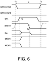
- the first DATA / Vdd data signal When the electronic circuit 200 is in “programming” mode, that is to say when the states memorized by the memory devices 102.1 and 102.2 are programmed, the first DATA / Vdd data signal then assumes a value similar to that of the second DATA / Gnd data signal.
- the electronic circuit 200 When the electronic circuit 200 is in “control” mode, that is to say when the memory devices 102.1 and 102.2 are used to control the setting to the on or off state of the second transistor 202, the first data signal DATA / Vdd is at state 1 (corresponding to the electric potential Vdd) and the second data signal DATA / Gnd is at state 0 (corresponding to a zero electric potential).
- the first DATA / Vdd data signal being by default (in “command” mode) at state 1, it is left at state 1 throughout the duration of "programming" mode when the first memory device 102.1 to intended to be programmed low and that the second memory device 102.2 is intended to be programmed high.
- the second DATA / Gnd data signal is by default (in "command” mode) at state 0, it goes to state 1 for the duration of programming, corresponding to t 2 -t 1 , of circuit 200.
- the signal SEL goes to state 1 during this duration d so that the transistor 112 is on and the inert electrode 108.1 of the first memory device 102.1 and the active electrode 106.2 of the second memory device 102.2 are on. are electrically connected to the first electrically conductive line 110 and subjected to the electric potential of the control signal WRITE during the programming phase of these devices.
- the programming duration of the memory devices 102.1 and 102.1 corresponding to the duration during which the signal SEL is at state 1, is therefore included in the duration d.
- the control signal WRITE passes from state 1 to state 0.
- the instant t 3 included between t 1 and t 2 , corresponds to the instant from which the WRITE control signal is at state 0.
- a signal to state 1 is applied to each of the two electrodes of each of the memory devices 102.1 and 102.2.
- the same electric potential is therefore applied to the two terminals 106, 108 of each of the memory devices 102.1 and 102.2, which is equivalent to the application of no voltage or of a zero voltage to the terminals of the memory devices 102.1 and 102.2 .
- the memory state MEM1 of the first memory device 102.1 and the memory state MEM2 of the second memory device 102.2 therefore do not change and remain in their respective initial state during this part of the duration d.
- the control signal WRITE is at state 0. Because the data signals DATA / Vdd and DATA / Gnd are always at state 1, the first memory device 102.1 therefore sees at its terminals a voltage of 0.5 V, that is to say here a positive electric potential of 0.5 V applied to its active electrode 106.1 and a zero electric potential applied to its inert electrode 108.1.
- the memory state MEM1 of the first memory device 102.1 then goes low at the instant t 3 if the initial memory state corresponds to the high state, or remains in the low state if the latter corresponds to l 'initial memory state MEM1.
- the second memory device 102.2 sees at its terminals a voltage equivalent to -0.5 V, that is to say here a positive electric potential of 0.5 V applied to its inert electrode 108.2 and a zero electric potential applied on its active electrode 106.2.
- the memory state MEM2 of the second memory device 102.2 then goes high at the instant t 3 if the initial memory state corresponds to the low state, or remains high if the latter corresponds to l 'MEM2 initial memory state.
- the electronic circuit 200 exits the “programming” mode to return to the “control” mode.
- the first data signal DATA / Vdd remains at state 1 and the second data signal DATA / Gnd returns to state 0.
- the signal SEL returns to state 0 before the data signal DATA / Gnd and / or the control signal WRITE change value and modify the states stored in the memory devices 102.1 and 102.2. The signal SEL therefore returns to state 0 between times t 3 and t 2 .
- the programming of the memory devices 102.1 and 102.2 is triggered by the passage from state 1 to state 0 of the control signal WRITE during the period d.
- the second DATA / Gnd data signal being by default (in "command" mode) at state 0, that is left at state 0 throughout the programming period when the first memory device 102.1 is intended to be programmed at the high state and that the second memory device 102.2 is intended to be programmed in the low state.
- the first data signal DATA / Vdd is by default at state 1, this goes to state 0 during the programming period.
- the signal SEL goes to state 1 so that the transistor 112 is on and the inert electrode 108.1 of the first memory device 102.1 and the active electrode 106.2 of the second memory device 102.2 are electrically connected to the first electrically conductive line 110.
- the signal SEL is at state 1 (at the instant t 4 ). Because the control signal WRITE is at state 1, the first memory device 102.1 therefore sees at its terminals, from time t 4 , a voltage equivalent to -0.5 V formed by a positive electric potential 0.5 V applied to the inert electrode 108.1 and a zero electric potential applied to the active electrode 106.1.
- the memory state MEM1 of the first memory device 102.1 passes or remains in the high state at the instant t 4 .
- the second memory device 102.2 sees at its terminals a voltage of 0.5 V (positive electric potential of 0.5 V applied to the active electrode 106.2 and zero electric potential applied to the inert electrode 108.2).
- the memory state MEM2 of the second memory device 102.2 goes or remains in the low state at the instant t 4 .
- the control signal WRITE passes from state 1 to state 0. This change of state does not affect the states stored in the memory devices 102.1 and 102.2 (equivalent to the application of a substantially zero voltage to the terminals of each of the memory devices 102.1 and 102.2).
- the signal SEL then returns to state 0 before the data signal DATA returns to state 1, that is to say before t 2 .
- control signal WRITE used for programming low of the first memory device 102.1 and high of the second memory device 102.2 is the same as that used for programming high of the first memory device 102.1 and in the low state of the second memory device 102.2.
- the electronic circuit 200 is in “control” mode.
- the transistor 202 is then controlled by the states stored in the memory devices 102.1 and 102.2.
- the voltage which is found applied to the gate of transistor 202 is then close to zero voltage, blocking the transistor 202 (represented by the signal Sw at state 0 on the figure 6 ).
- the time for one of the memory devices 102.1 or 102.2 to go from the high state to the low state is less than the time for the other memory device to go from the low state to high state (on figures 5 and 6 , these times are represented as being equivalent for reasons of simplification). Thus, this prevents the electronic circuit 200 from ending up in an undesirable transient state in which the two memory devices 102.1 and 102.2 are simultaneously low.
- the wiring of the electronic circuit 200 is modified such that the active electrode 106.1 of the first memory device 102.1 and the inert electrode 108.2 of the second memory device 102.2 are electrically connected to the source of the selection transistor 112, and that the DATA / Vdd and DATA / Gnd signals are intended to be applied respectively to the inert electrode 108.1 of the first memory device 102.1 and to the active electrode 106.2 of the second memory device 102.2.
- the states stored in the memory devices 102.1 and 102.2 would be inverted with respect to those previously described in connection with these figures.
- control signal WRITE changes from state 0 to state 1. It is also possible that the part of the time d during which the control signal WRITE is at state 0 is shorter or longer than that during which the control signal WRITE is at state. 1.
- the two inert electrodes 108.1 and 108.2 (or the two active electrodes 106.1 and 106.2) of the two memory devices 102.1 and 102.2 are electrically connected to the source of the transistor 112.
- the first DATA / Vdd data signal applied to the active electrode 106.1 (or the inert electrode 108.1) of the first memory device 102.1 has the inverse value of the second DATA / Gnd data signal applied to the active electrode 106.2 (the inert electrode 108.2) of the second memory device 102.2.
- the figure 7 shows another electronic circuit 300 according to a third embodiment using bipolar non-volatile memory devices programmed two by two in a complementary manner as previously described for the electronic circuit 200.
- the electronic circuit 300 is here a correspondence table (or LUT for Look-Up Table) of the FPGA type comprising an n-bit multiplexer 302, with n integer greater than 1.
- Each of the n inputs of the multiplexer 302 is connected to one of the memory elements 304.1 to 304.n each formed by two devices memories 102.1 and 102.2, similar to those previously described, programmed in a complementary manner, and of a selection transistor 112.
- the multiplexer 302 can output the values stored in the memory elements 304.1 to 304.n, and therefore in the memory devices 102.1 and 102.2 of these memory elements, as a function of control signals, or addressing signals, applied at the input of multiplexer 3 02.
- the figure 8 shows another electronic circuit 400 according to a fourth embodiment corresponding to a system of programmable interconnections.
- This circuit 400 comprises in particular two inputs 402.1, 402.2, two outputs 404.1, 404.2 corresponding to the outputs of two inverters 405.1 and 405.2, and four bipolar non-volatile memory devices 102.1 to 102.4.
- the circuit 400 is able to deliver to one and / or the other of the two outputs 404.1, 404.2 the values of the signals applied to one and / or the other of the two inputs 402.1, 402.2 depending on the high state or bottom of each of the four memory devices 102.1 - 102.4.
- the 0 and 1 states that the outputs 404.1 and 404.2 can take can correspond respectively to a zero reference voltage and a voltage V DD for example equal to 0.5 V.
- each of the four memory devices 102.1 - 102.4 is carried out in a manner analogous to that previously described in connection with the figures 1 to 3 .
- the control signal WRITE is intended to be applied to the inert electrodes of the first and of the second memory devices 102.1 and 102.2 when a first selection transistor 112.1 is on, the on or off state of this first selection transistor 112.1 being controlled. via a SELWL signal applied to the gate of this transistor 112.1.
- This same control signal WRITE is also intended to be applied to the inert electrodes of the third and of the fourth memory device 102.3, 102.4 when a second selection transistor 112.2 is on, the on or off state of this second selection transistor 112.2 being controlled via a signal SELWH applied to the gate of this transistor 112.2.
- a first data signal DATA0 is intended to be applied to the active electrodes of the first and of the third memory device 102.1, 102.3 when a third selection transistor 112.3 is on, the on or off state of this third selection transistor 112.2 being controlled via a SELW signal applied to the gate of this transistor 112.3.
- a second data signal DATA1 is intended to be applied to the active electrode 106.2 of the second and of the fourth memory device 102.2, 102.4 when a fourth selection transistor 112.4 is on, the on or off state of this fourth selection transistor 112.4 being controlled via the signal SELW applied to the gate of this transistor 112.4.
- the first memory device 102.1 and the third memory device 102.3 are programmed in a complementary manner in order to avoid simultaneously interconnecting the two inputs 402.1 and 402.2 on the single output 404.1.
- the second memory device 102.2 and fourth memory device 102.4 are programmed in a complementary manner in order to avoid simultaneously interconnecting the two inputs 402.1 and 402.2 on the output 404.2.
- the first input 402.1 is connected to the input of a first 3-state (or “tri-state”) gate 406.1, formed by two PMOS transistors and two NMOS transistors and also receiving as input the signal SELW and another signal SELWB which is complementary to the signal SELW (that is to say will be at state 1 when SELW will be at state 0, and vice versa).
- a first 3-state gate 406.1 formed by two PMOS transistors and two NMOS transistors and also receiving as input the signal SELW and another signal SELWB which is complementary to the signal SELW (that is to say will be at state 1 when SELW will be at state 0, and vice versa).
- the second input 402.2 is connected to the input of a second 3-state gate 406.2 also receiving as input the signals SELW and SELWB.
- Circuit 400 is in switching mode (as opposed to programming mode in which the memory states of the memory devices 102.1 - 102.4 are defined), in which it switches the inputs 402.1, 402.2 to the desired outputs 404.1, 404.2, when the signal SELW is at state 0, that the signal SELWB is state 1, and that the signals SELWL and SELWH are at state 0.
- state 0 or 1 applied to the first input 402.1 is found on the inert electrodes of the first and of the second memory device 102.1, 102.2
- the state 0 or 1 applied to the second input 402.2 is found on the inert electrodes of the third and of the fourth memory device 102.3, 102.4.
- states 0 or 1 of one and / or other of inputs 402.1 and 402.2 are found on one and / or the other of outputs 404.1, 404.2 .
- This programming of the memory devices in two distinct phases also makes it possible to avoid short-circuiting the two inputs 402.1, 402.2 between them.
- the signal SELW goes to state 1 and the signal SELWB goes to state 0, thus switching the circuit 400 to programming mode .
- the SELWL signal goes to state 1 and the SELWH signal is to state 0, which implies that only the two memory devices 102.1 and 102.2 will be programmed (because state 1 of SELWL makes the first selection transistor 112.1 on and that state 0 of SELWH blocks the second selection transistor 112.2).
- the control signal WRITE goes from state 1 to state 0, which causes the storage of the state of the data signal DATA0 in the first memory device 102.1 and the storage of the state of the data signal DATA1 in the second memory device 102.2.
- the signal SELW goes to state 0 and the signal SELWB goes to state 1, thus causing the circuit 400 to pass into switching mode.
- the states of the inputs 402.1, 402.2 are then routed to the outputs 404.1, 404.2 according to the storage states of the memory devices 102.1 - 102.4.
- the signals SELWL and SELWH are at state 0 in order to prevent the control signal WRITE from disturbing the routing of the input signals.
- the SELW signal returns to state 1 and the SELWB signal returns to state 0, thus switching circuit 400 to programming mode .
- the SELWL signal remains at state 1 and the SELWH signal changes to state 1, which implies that only the two memory devices 102.3 and 102.4 will be programmed (because state 1 of SELWH makes the second selection transistor 112.2 on and that state 0 of SELWL blocks the first selection transistor 112.1).
- the control signal WRITE changes from state 0 to state 1, which causes the storage of the state of the data signal DATA0 in the third memory device 102.3 and the storage of the state of the data signal DATA1 in the fourth memory device 102.4.
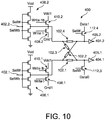
- FIG. 10 An alternative embodiment of the electronic circuit 400 is shown in figure 10 .
- the selection transistors 112.1 and 112.2 are each replaced by two complementary PMOS and NMOS transistors referenced 408.1, 410.1, 408.2 and 410.2 which, depending on the states of four signals WRITEL, WRITELB, WRITEH and WRITEHB (with WRITELB complementary to WRITEL, and WRITEHB complementary to WRITEH), apply a potential V DD1 or a zero reference potential Gnd1 to the inert electrodes of the memory devices 102.1-102.4.
- This variant embodiment makes it possible to clearly dissociate the operating voltages and the programming voltages, which makes it possible to avoid, in normal operation (transmission of signals from the input to the output), from modifying the state of the resistors. Voltages below the resistance programming threshold are used in this case.
- a flip-flop consists of two locking devices, or latchs, connected in series: one of the master type and the other of the slave type.
- part of the slave interlock device holds information and is able to restore it when power is restored.
- resistive memory devices in the slave locking device (or the master), as described for example in the document of W. Zhao et al., “Spin-MTJ based Non-Volatile Flip-Flop”, Proceedings of the 7th IEEE International Conf
- Bipolar non-volatile memory devices programmed via a method similar to that described above can advantageously be used to produce such locking devices.
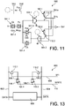
- the figure 11 shows an electronic circuit 500 according to a fifth embodiment comprising bipolar non-volatile memory devices programmed in a manner analogous to the memory devices described above.
- This electronic circuit 500 represents the slave locking device of a retention latch using two resistive bipolar memory devices 102.1 and 102.2 which are programmed in a manner analogous to that previously described.
- the two memory devices 102.1 and 102.2 here have the same orientation, that is to say each have their active electrode electrically connected to a common input to which a control signal WRITE is applied.
- the device 500 has an “In” input and four CMOS transmission gates 501.1 to 501.4 controlled by signals Ck and Pu (and their complementary signals Ckb and Pub) and an “Out” output.
- the internal state of the device 500 corresponding to the outputs of two CMOS inverters 504.1 and 504.2 whose inputs are connected to the CMOS transmission gates 501.2 to 501.4, is copied into the two memory devices 102.1 and 102.2 by making two access transistors conductive. 112.1 and 112.2 via a selection signal SPu applied to their gates (the inert electrodes of memory devices 102.1 and 102.2 are connected to the drains of transistors 112.1 and 112.2 respectively), then by performing a transition (change from state 0 to state 1, or change from state 1 to state 0) on the WRITE signal.
- One of the two memory devices 102.1, 102.2 is programmed during state 1 of the WRITE signal, and the other is programmed during state 0 of the WRITE signal.
- the 510 signals shown on the figure 12 correspond to the signals Ck, Pu, SPu and WRITE during this programming phase of the memory devices 102.1 and 102.2.
- the two memory devices 102.1 and 102.2 are used to reset the internal nodes of the device 500 to the starting state, at the outputs of the CMOS inverters 504.1 and 504.2.
- the signal Pu is activated (mi at state 1) to loop back the device 500 and disconnect it from the master locking device to which the slave locking device 500 is coupled.
- the memory devices 102.1 and 102.2 are connected. to the internal nodes by activating the signal SPu (set to state 1).
- the WRITE signal goes to state 1 (link to Vdd).
- the resistors of the memory devices 102.1 and 102.2 (one in the high state and the other in the low state) create an imbalance which will force the slave locking device 500 to its initial state. .
- the additional programming of the memory devices 102.1 and 102.2 makes it possible to correctly reset the slave locking device 500 on re-energization, and this naturally because the two internal nodes of the circuit are always in opposite states (because they are separated by an inverter). .
- the circles shown in dotted lines each correspond to a MOS transistor making it possible to apply or not the voltage Vdd to the CMOS inverters 504.1 and 504.2.
- the 512 signals shown on the figure 12 correspond to the WRITE, Pu, SPu and vdd signals during this phase of re-energizing the slave locking device 500.
- the figure 13 shows an electronic circuit 600 according to a sixth embodiment forming a differential cell of RRAM type and comprising bipolar non-volatile memory devices programmed in a manner analogous to memory devices previously described. Such a cell is in particular intended to form one of the multiple memory cells of a memory circuit.
- the circuit 600 comprises a first memory device 102.1, the inert electrode 108.1 of which is connected to a first electrically conductive line 110 (which could be arranged in a column and connected to other memory devices) to which is applied a control signal WRITE and whose active electrode 106.1 is connected to the source of a first access transistor 112.1, and also comprises a second memory device 102.2 whose inert electrode 108.2 is also connected to the first electrically conductive line 110 and whose electrode active 106.2 is connected to the source of a second access transistor 112.2.
- the drain of the first access transistor 112.1 is connected to a second electrically conductive line 602 on which is applied a first data signal DATA and the drain of the second access transistor 112.2 is connected to a third electrically conductive line 604 on which is applied. applied a second data signal / DATA whose state is complementary to that of the first data signal DATA.
- the electrically conductive lines 602 and 604 are oriented in a column so that they can be connected to other memory cells.
- the gates of the two transistors 112.1 and 112.2 are connected to a fourth electrically conductive line 606 to which a selection signal SEL is applied.
- the two memory devices 102.1 and 102.2 are intended to be programmed in a complementary manner.
- the fourth electrically conductive line 606 corresponds to a word select line.
- the access transistors make it possible, in addition to accessing the memory devices 102.1 and 102.2 when programming these devices, to limit the current flowing through these memory devices 102.1 and 102.2.
- the figure 14 represents a timing diagram of the signals of circuit 600 during programming of memory devices 102.1 and 102.2.
- the first data signal DATA goes to state 1 and the second data signal / DATA goes to state 0.
- the control signal WRITE passes also at state 1 at approximately time t 1 (or remains at state 1).
- the signal SEL goes to state 1, thus turning on the access transistors 112.1 and 112.2, and thus causing the second memory device 102.2 to go high.
- the control signal WRITE goes to state 0, causing the first memory device 102.1 to go low.
- the signal SEL returns to state 0.
- the data signals DATA and / DATA can then change state without modifying the memory state of the memory devices 102.1 and 102.2.
- the programming variants described above can apply to the programming of the memory devices 102.1, 102.2 of this circuit 600.
- Such a differential memory cell can be coupled to one or more SRAM 608 type memory cells programmed via the same DATA and / DATA data signals.
- the inert electrode of one of the memory devices 102.1, 102.2 is connected to the source of the corresponding access transistor, and that the active electrode of this memory device is then connected to the first line electrically conductive 110.
- the same data signal passes over the electrically conductive lines 602 and 604.
- the two memory devices 102.1 and 102.2 are then programmed during the same part of the duration d (when the WRITE signal is at state 0 or 1).
- the duration of programming from the high state to the low state is less than the duration of programming from the low state to the high state, this prevents the circuit 600 from ending up in an undesirable transient state. in which the two memory devices 102.1 and 102.2 would be in the low state simultaneously.
- the electronic circuits 100 to 600 are generally produced in large numbers within FPGA type circuits, in which the signals used are pooled between all the electronic circuits.
Landscapes
- Chemical & Material Sciences (AREA)
- Engineering & Computer Science (AREA)
- Materials Engineering (AREA)
- Semiconductor Memories (AREA)
- Read Only Memory (AREA)
Claims (6)
- Elektronische Schaltung (200), umfassend eine erste Speichervorrichtung (102.1) mit bipolarer Umschaltung, umfassend eine erste Elektrode (106.1) und eine zweite Elektrode (108.1), an deren Anschlüssen eine Programmierspannung, die dazu ausgelegt ist, die erste Speichervorrichtung (102.1) in einen Zustand mit hohem Widerstand oder mit niedrigem Widerstand zu programmieren, angelegt werden kann, wobei die elektronische Schaltung (200) umfasst:- eine Selektionsvorrichtung (112), die elektrisch mit der ersten Speichervorrichtung (102.1) verbunden ist, und einen ersten Transistor umfasst, der eine erste Source- oder Drain-Elektrode hat, die mit der zweiten Elektrode (108.1) der ersten Speichervorrichtung (102.1) verbunden ist, wobei dieser erste Transistor ein MOS-Transistor ist;- eine zweite Speichervorrichtung (102.2), die dazu ausgelegt ist, in einen Zustand komplementär zu jenem programmiert zu sein, in den die erste Speichervorrichtung (102.1) programmiert werden kann, wobei die zweite Elektrode (108.1) der ersten Speichervorrichtung (102.1) elektrisch mit einer von einer ersten Elektrode (106.2) und einer zweite Elektrode (108.2) der zweiten Speichervorrichtung (102.2) verbunden ist,wobei die erste und die zweite Speichervorrichtung (102.1, 102.2) eine Spannungsteilerbrücke bilden, bei der eine Ausgangsspannung an der zweiten Elektrode (108.1) der ersten Speichervorrichtung (102, 102.1) erhalten wird, wobei die elektronische Schaltung ferner einen zweiten MOS-Transistor (202) umfasst, dessen Durchlass- oder Sperrzustand eine Funktion der komplementären Zustände der ersten Speichervorrichtung (102.1) und der zweiten Speichervorrichtung (102.2) ist, und dessen Steuergate elektrisch mit der zweiten Elektrode der ersten Speichervorrichtung (102.1) verbunden ist;wobei die elektronische Schaltung (200) dadurch gekennzeichnet ist, dass sie umfasst:- erste Mittel (114), die dazu ausgelegt sind, an die erste Elektrode (106.1) der ersten Speichervorrichtung (102.1) ein Datensignal anzulegen, das während einer Dauer d einen konstanten Zustand 0 oder 1 aufweist, der für den Zustand repräsentativ ist, in den die erste Speichervorrichtung (102.1) programmiert werden kann,- zweite Mittel (110), die dazu ausgelegt sind, an eine zweite Drain- oder Sourceelektrode des ersten Transistors ein Steuersignal anzulegen, das im Verlauf der Dauer d wenigstens eine Alternierung eines Zustands 1 und eines Zustands 0 aufweist, wobei dieses Steuersignal während einer Programmierung der ersten Speichervorrichtung (102.1) in einem Zustand mit hohem Widerstand oder in einem Zustand mit niedrigem Widerstand ähnlich ist,wobei die Zustände 0 und 1 des Datensignals und des Steuersignals elektrischen Potenzialen von Null beziehungsweise positiv entsprechen, die dazu ausgelegt sind, die Programmierspannung zu bilden, wenn eines von dem Datensignal und dem Steuersignal im Zustand 0 ist und das andere von dem Datensignal und dem Steuersignal im Zustand 1 ist,wobei die elektronische Schaltung (200) ferner Mittel zur Steuerung des Gates des ersten Transistors umfasst, die dazu konfiguriert sind, während eines Schreibzyklus ausschließlich während einer Programmierdauer, die streng in der Dauer d enthalten ist, den Durchlass eines Stroms durch den ersten Transistor hindurch zu erlauben, um an die Anschlüsse der ersten und der zweiten Elektrode (106.1, 108.1) der ersten Speichervorrichtung (102.1) die Programmierspannung anzulegen,wobei der Übergang von einem der Zustände 0 und 1 des Steuersignals in den anderen der Zustände 0 und 1 des Steuersignals dazu ausgelegt ist, während der Programmierdauer gesteuert zu werden,und ferner umfassend dritte Mittel, die dazu ausgelegt sind, ein zweites Datensignal an die andere von der ersten Elektrode (106.2) und der zweiten Elektrode (108.2) der zweiten Speichervorrichtung (102.2) anzulegen.
- Elektronische Schaltung (200) nach Anspruch 1, bei der die erste und die zweite Speichervorrichtung (102, 102.1, 102.2) vom Typ CBRAM oder RRAM sind, wobei die ersten Elektroden (106, 106.1, 106.2) und die zweiten Elektroden (108, 108.1, 108.2) der ersten und der zweiten Speichervorrichtung (102, 102.1, 102.2) aktiven Elektroden beziehungsweise inerten Elektroden der ersten und der zweiten Speichervorrichtung (102, 102.1, 102.2) entsprechen, oder umgekehrt.
- Elektronische Schaltung (200) nach einem der vorhergehenden Ansprüche, bei der das Steuersignal während eines ersten Teils der Dauer d im Zustand 1 ist und während eines zweiten Teils der Dauer d im Zustand 0 ist, wobei der erste Teil der Dauer d einer kürzeren oder längeren Dauer entspricht als jene des zweiten Teils der Dauer d.
- Elektronische Schaltung (200) nach einem der vorhergehenden Ansprüche, bei der das Steuersignal im Verlauf der Dauer d mehrere Alternierungen zwischen den Zuständen 1 und 0 aufweist.
- Elektronische Schaltung (200) nach einem der vorhergehenden Ansprüche, bei der die zweiten Mittel eine erste elektrisch leitfähige Leitung (110) umfassen, die elektrisch mit der zweiten Elektrode des ersten Transistors (112) verbunden ist.
- Speicherschaltung, umfassend mehrere elektronische Schaltungen (200) nach einem der vorhergehenden Ansprüche, bei der die zweiten Mittel (114, 110) von jeder elektronischen Schaltung (200) mehreren elektronischen Schaltungen (200) gemeinsam sind.
Applications Claiming Priority (2)
| Application Number | Priority Date | Filing Date | Title |
|---|---|---|---|
| FR1350796A FR3001571B1 (fr) | 2013-01-30 | 2013-01-30 | Procede de programmation d'un dispositif memoire a commutation bipolaire |
| PCT/EP2014/051753 WO2014118255A1 (fr) | 2013-01-30 | 2014-01-30 | Procede de programmation d'un dispositif memoire resistif a commutation bipolaire |
Publications (2)
| Publication Number | Publication Date |
|---|---|
| EP2951833A1 EP2951833A1 (de) | 2015-12-09 |
| EP2951833B1 true EP2951833B1 (de) | 2021-09-22 |
Family
ID=48170704
Family Applications (1)
| Application Number | Title | Priority Date | Filing Date |
|---|---|---|---|
| EP14702536.5A Not-in-force EP2951833B1 (de) | 2013-01-30 | 2014-01-30 | Programmierung von bipolarem widerstandsspeicher |
Country Status (4)
| Country | Link |
|---|---|
| US (1) | US10566055B2 (de) |
| EP (1) | EP2951833B1 (de) |
| FR (1) | FR3001571B1 (de) |
| WO (1) | WO2014118255A1 (de) |
Families Citing this family (15)
| Publication number | Priority date | Publication date | Assignee | Title |
|---|---|---|---|---|
| TWI570723B (zh) * | 2015-02-16 | 2017-02-11 | 華邦電子股份有限公司 | 電阻式記憶體及量測該電阻式記憶體的量測系統 |
| US10048893B2 (en) * | 2015-05-07 | 2018-08-14 | Apple Inc. | Clock/power-domain crossing circuit with asynchronous FIFO and independent transmitter and receiver sides |
| US9627058B2 (en) * | 2015-06-17 | 2017-04-18 | Macronix International Co., Ltd. | Resistance random access memory with accurate forming procedure, operating method thereof and operating system thereof |
| CN105118528B (zh) * | 2015-07-14 | 2017-11-24 | 江苏时代全芯存储科技有限公司 | 非挥发性记忆装置、可编程电路以及内容可定址记忆体 |
| CN105097023B (zh) * | 2015-07-22 | 2017-12-12 | 江苏时代全芯存储科技有限公司 | 非挥发性存储单元以及非挥发性存储装置 |
| US9577009B1 (en) * | 2015-11-13 | 2017-02-21 | Taiwan Semiconductor Manufacturing Co., Ltd. | RRAM cell with PMOS access transistor |
| WO2017131628A1 (en) | 2016-01-26 | 2017-08-03 | Hewlett Packard Enterprise Development Lp | Memristive bit cell with switch regulating components |
| GB2548081B (en) * | 2016-02-23 | 2019-10-02 | Univ Oxford Brookes | Logic gate |
| US20200295761A1 (en) * | 2016-05-13 | 2020-09-17 | Nec Corporation | Reconfigurable circuit and the method for using the same |
| US10348306B2 (en) | 2017-03-09 | 2019-07-09 | University Of Utah Research Foundation | Resistive random access memory based multiplexers and field programmable gate arrays |
| US10319439B1 (en) | 2018-05-15 | 2019-06-11 | International Business Machines Corporation | Resistive processing unit weight reading via collection of differential current from first and second memory elements |
| US10754921B2 (en) * | 2019-01-16 | 2020-08-25 | International Business Machines Corporation | Resistive memory device with scalable resistance to store weights |
| DE102019132067A1 (de) | 2019-01-25 | 2020-07-30 | Taiwan Semiconductor Manufacturing Co., Ltd. | Strombegrenzer für speichervorrichtung |
| US10991426B2 (en) * | 2019-01-25 | 2021-04-27 | Taiwan Semiconductor Manufacturing Company, Ltd. | Memory device current limiter |
| FR3161980A1 (fr) * | 2024-05-03 | 2025-11-07 | Commissariat à l'Energie Atomique et aux Energies Alternatives | Lecture différentielle multi-valuée d’un dispositif mémoire |
Family Cites Families (36)
| Publication number | Priority date | Publication date | Assignee | Title |
|---|---|---|---|---|
| US6295241B1 (en) * | 1987-03-30 | 2001-09-25 | Kabushiki Kaisha Toshiba | Dynamic random access memory device |
| KR900015148A (ko) * | 1989-03-09 | 1990-10-26 | 미다 가쓰시게 | 반도체장치 |
| US5250856A (en) * | 1989-12-28 | 1993-10-05 | North American Philips Corp. | Differential input buffer-inverters and gates |
| US5204541A (en) * | 1991-06-28 | 1993-04-20 | Texas Instruments Incorporated | Gated thyristor and process for its simultaneous fabrication with high- and low-voltage semiconductor devices |
| JPH10172287A (ja) * | 1996-12-05 | 1998-06-26 | Mitsubishi Electric Corp | スタティック型半導体記憶装置 |
| US6229161B1 (en) * | 1998-06-05 | 2001-05-08 | Stanford University | Semiconductor capacitively-coupled NDR device and its applications in high-density high-speed memories and in power switches |
| US6413806B1 (en) * | 2000-02-23 | 2002-07-02 | Motorola, Inc. | Semiconductor device and method for protecting such device from a reversed drain voltage |
| JP2002093154A (ja) * | 2000-09-11 | 2002-03-29 | Oki Electric Ind Co Ltd | 強誘電体メモリ |
| JP4691624B2 (ja) * | 2003-03-31 | 2011-06-01 | 学校法人近畿大学 | ラティラルバイポーラcmos集積回路 |
| WO2006073060A1 (ja) * | 2004-12-16 | 2006-07-13 | Nec Corporation | 半導体記憶装置 |
| US7599210B2 (en) * | 2005-08-19 | 2009-10-06 | Sony Corporation | Nonvolatile memory cell, storage device and nonvolatile logic circuit |
| US7511532B2 (en) | 2005-11-03 | 2009-03-31 | Cswitch Corp. | Reconfigurable logic structures |
| US7209384B1 (en) * | 2005-12-08 | 2007-04-24 | Juhan Kim | Planar capacitor memory cell and its applications |
| US20070217266A1 (en) * | 2005-12-11 | 2007-09-20 | Juhan Kim | Static random access memory |
| US20070132049A1 (en) | 2005-12-12 | 2007-06-14 | Stipe Barry C | Unipolar resistance random access memory (RRAM) device and vertically stacked architecture |
| CN101542730B (zh) * | 2007-06-05 | 2011-04-06 | 松下电器产业株式会社 | 非易失性存储元件和其制造方法、以及使用了该非易失性存储元件的非易失性半导体装置 |
| US7869251B2 (en) * | 2008-09-26 | 2011-01-11 | Lsi Corporation | SRAM based one-time-programmable memory |
| US7974117B2 (en) | 2008-10-30 | 2011-07-05 | Seagate Technology Llc | Non-volatile memory cell with programmable unipolar switching element |
| US8630113B1 (en) * | 2008-11-25 | 2014-01-14 | Altera Corporation | Apparatus for memory with improved performance and associated methods |
| KR101549979B1 (ko) | 2009-03-02 | 2015-09-03 | 삼성전자주식회사 | 양방향 저항성 메모리 장치, 이를 포함하는 메모리 시스템,및 그것의 데이터 입력 방법 |
| JP5001464B2 (ja) * | 2010-03-19 | 2012-08-15 | パナソニック株式会社 | 不揮発性記憶素子、その製造方法、その設計支援方法および不揮発性記憶装置 |
| JP5333311B2 (ja) * | 2010-03-26 | 2013-11-06 | ソニー株式会社 | 不揮発性記憶装置 |
| JP5589577B2 (ja) * | 2010-06-10 | 2014-09-17 | ソニー株式会社 | 抵抗変化型メモリデバイス |
| US8355271B2 (en) * | 2010-11-17 | 2013-01-15 | Sandisk 3D Llc | Memory system with reversible resistivity-switching using pulses of alternate polarity |
| JP2012203944A (ja) * | 2011-03-24 | 2012-10-22 | Toshiba Corp | 抵抗変化型メモリ |
| US8451675B2 (en) * | 2011-03-31 | 2013-05-28 | Mosys, Inc. | Methods for accessing DRAM cells using separate bit line control |
| US8526220B2 (en) * | 2011-06-12 | 2013-09-03 | International Business Machines Corporation | Complementary SOI lateral bipolar for SRAM in a low-voltage CMOS platform |
| WO2012178114A2 (en) * | 2011-06-24 | 2012-12-27 | Rambus Inc. | Resistance memory cell |
| US8760790B2 (en) * | 2012-03-08 | 2014-06-24 | Lsi Corporation | Analog tunneling current sensors for use with disk drive storage devices |
| US8854902B2 (en) * | 2012-05-18 | 2014-10-07 | Stmicroelectronics International N.V. | Write self timing circuitry for self-timed memory |
| US9030886B2 (en) * | 2012-12-07 | 2015-05-12 | United Microelectronics Corp. | Memory device and driving method thereof |
| FR3001310B1 (fr) | 2013-01-21 | 2015-02-27 | Commissariat Energie Atomique | Interface de reseau sur puce dotee d'un systeme adaptatif de declenchement d'envoi de donnees |
| FR3009772B1 (fr) | 2013-08-14 | 2015-09-25 | Commissariat Energie Atomique | Circuit logique a interrupteurs mecaniques a faible consommation |
| JP5841212B1 (ja) * | 2014-09-04 | 2016-01-13 | トヨタ自動車株式会社 | 電源システム |
| US9460771B2 (en) * | 2014-09-25 | 2016-10-04 | Kilopass Technology, Inc. | Two-transistor thyristor SRAM circuit and methods of operation |
| WO2016167756A1 (en) * | 2015-04-15 | 2016-10-20 | Hewlett Packard Enterprise Development Lp | Resistive random access memory (rram) system |
-
2013
- 2013-01-30 FR FR1350796A patent/FR3001571B1/fr not_active Expired - Fee Related
-
2014
- 2014-01-30 EP EP14702536.5A patent/EP2951833B1/de not_active Not-in-force
- 2014-01-30 US US14/764,790 patent/US10566055B2/en not_active Expired - Fee Related
- 2014-01-30 WO PCT/EP2014/051753 patent/WO2014118255A1/fr not_active Ceased
Also Published As
| Publication number | Publication date |
|---|---|
| FR3001571A1 (fr) | 2014-08-01 |
| US10566055B2 (en) | 2020-02-18 |
| EP2951833A1 (de) | 2015-12-09 |
| US20150371705A1 (en) | 2015-12-24 |
| FR3001571B1 (fr) | 2016-11-25 |
| WO2014118255A1 (fr) | 2014-08-07 |
Similar Documents
| Publication | Publication Date | Title |
|---|---|---|
| EP2951833B1 (de) | Programmierung von bipolarem widerstandsspeicher | |
| EP2993786B1 (de) | Mit einer nicht-flüchtigen absicherung ausgestattetes gatter c | |
| EP1438722B1 (de) | Magnetspeicher mit schreibsperrauswahl und schreibverfahren dafür | |
| FR2976712A1 (fr) | Element de memoire non-volatile | |
| FR3009421A1 (fr) | Cellule memoire non volatile | |
| EP3154061B1 (de) | Verfahren und schaltkreis zur steuerung des stroms einer programmierung in einer nicht-flüchtigen speichermatrix | |
| FR2970592A1 (fr) | Cellule mémoire volatile/non volatile programmable | |
| EP2821998B1 (de) | Nichtflüchtige Speichervorrichtung | |
| FR2970590A1 (fr) | Cellule mémoire volatile/non volatile sans charge | |
| FR2976711A1 (fr) | Cellule memoire avec memorisation volatile et non volatile | |
| EP2425434A1 (de) | Memristor-bauelement mit einem widerstand, der durch bewegen einer magnetischen wand durch spintransfer einstellbar ist, und verwendung des memristors in einem neuronalen netzwerk | |
| EP3010022A1 (de) | Speicherzelle mit lese-transistoren vom typ tfet und mosfet | |
| EP4078678A1 (de) | Elementarzelle, die einen resistiven speicher und eine vorrichtung zum bilden eines selektors umfasst, zellenmatrix, zugehörige herstellungs- und initialisierungsverfahren | |
| EP2689422A1 (de) | Logische speicherarchitektur, insbesondere für mram, pcram oder rram | |
| EP2987168B1 (de) | Speicherzelle mit nichtflüchtigem datenspeicher | |
| EP4224477A1 (de) | Dreidimensionale speicherstruktur zur speicherberechnung | |
| FR3104812A1 (fr) | Cellule elementaire comportant une memoire resistive et procede d’initialisation associe | |
| EP2987167B1 (de) | Nichtflüchtiger speicher | |
| FR2979737A1 (fr) | Cellule memoire sram non volatile amelioree | |
| EP4198985A1 (de) | Resistiver speicher mit selektor ausgestattet mit schreibkondensator und schreibverfahren dafür | |
| EP2685457B1 (de) | Nicht-flüchtiges elektronisches Logikmodul | |
| EP4697332A1 (de) | Magnetoresistiver speicher mit integrierten wählern | |
| FR3035998A1 (fr) | Non-volatile memory with programming circuit | |
| FR2970591A1 (fr) | Cellule mémoire volatile et non volatile combinee | |
| WO2012069719A2 (fr) | Mémoire électronique |
Legal Events
| Date | Code | Title | Description |
|---|---|---|---|
| PUAI | Public reference made under article 153(3) epc to a published international application that has entered the european phase |
Free format text: ORIGINAL CODE: 0009012 |
|
| 17P | Request for examination filed |
Effective date: 20150806 |
|
| AK | Designated contracting states |
Kind code of ref document: A1 Designated state(s): AL AT BE BG CH CY CZ DE DK EE ES FI FR GB GR HR HU IE IS IT LI LT LU LV MC MK MT NL NO PL PT RO RS SE SI SK SM TR |
|
| AX | Request for extension of the european patent |
Extension state: BA ME |
|
| RIN1 | Information on inventor provided before grant (corrected) |
Inventor name: BELLEVILLE, MARC Inventor name: CLERMIDY, FABIEN Inventor name: ONKARAIAH, SANTHOSH |
|
| DAX | Request for extension of the european patent (deleted) | ||
| STAA | Information on the status of an ep patent application or granted ep patent |
Free format text: STATUS: EXAMINATION IS IN PROGRESS |
|
| 17Q | First examination report despatched |
Effective date: 20180502 |
|
| GRAP | Despatch of communication of intention to grant a patent |
Free format text: ORIGINAL CODE: EPIDOSNIGR1 |
|
| STAA | Information on the status of an ep patent application or granted ep patent |
Free format text: STATUS: GRANT OF PATENT IS INTENDED |
|
| RIN1 | Information on inventor provided before grant (corrected) |
Inventor name: CLERMIDY, FABIEN Inventor name: BELLEVILLE, MARC Inventor name: ONKARAIAH, SANTHOSH |
|
| INTG | Intention to grant announced |
Effective date: 20210507 |
|
| GRAS | Grant fee paid |
Free format text: ORIGINAL CODE: EPIDOSNIGR3 |
|
| GRAA | (expected) grant |
Free format text: ORIGINAL CODE: 0009210 |
|
| STAA | Information on the status of an ep patent application or granted ep patent |
Free format text: STATUS: THE PATENT HAS BEEN GRANTED |
|
| AK | Designated contracting states |
Kind code of ref document: B1 Designated state(s): AL AT BE BG CH CY CZ DE DK EE ES FI FR GB GR HR HU IE IS IT LI LT LU LV MC MK MT NL NO PL PT RO RS SE SI SK SM TR |
|
| REG | Reference to a national code |
Ref country code: GB Ref legal event code: FG4D Free format text: NOT ENGLISH |
|
| REG | Reference to a national code |
Ref country code: IE Ref legal event code: FG4D Free format text: LANGUAGE OF EP DOCUMENT: FRENCH |
|
| REG | Reference to a national code |
Ref country code: DE Ref legal event code: R096 Ref document number: 602014080238 Country of ref document: DE |
|
| REG | Reference to a national code |
Ref country code: CH Ref legal event code: EP Ref country code: AT Ref legal event code: REF Ref document number: 1432941 Country of ref document: AT Kind code of ref document: T Effective date: 20211015 |
|
| REG | Reference to a national code |
Ref country code: LT Ref legal event code: MG9D |
|
| REG | Reference to a national code |
Ref country code: NL Ref legal event code: MP Effective date: 20210922 |
|
| PG25 | Lapsed in a contracting state [announced via postgrant information from national office to epo] |
Ref country code: BG Free format text: LAPSE BECAUSE OF FAILURE TO SUBMIT A TRANSLATION OF THE DESCRIPTION OR TO PAY THE FEE WITHIN THE PRESCRIBED TIME-LIMIT Effective date: 20211222 Ref country code: LT Free format text: LAPSE BECAUSE OF FAILURE TO SUBMIT A TRANSLATION OF THE DESCRIPTION OR TO PAY THE FEE WITHIN THE PRESCRIBED TIME-LIMIT Effective date: 20210922 Ref country code: FI Free format text: LAPSE BECAUSE OF FAILURE TO SUBMIT A TRANSLATION OF THE DESCRIPTION OR TO PAY THE FEE WITHIN THE PRESCRIBED TIME-LIMIT Effective date: 20210922 Ref country code: NO Free format text: LAPSE BECAUSE OF FAILURE TO SUBMIT A TRANSLATION OF THE DESCRIPTION OR TO PAY THE FEE WITHIN THE PRESCRIBED TIME-LIMIT Effective date: 20211222 Ref country code: SE Free format text: LAPSE BECAUSE OF FAILURE TO SUBMIT A TRANSLATION OF THE DESCRIPTION OR TO PAY THE FEE WITHIN THE PRESCRIBED TIME-LIMIT Effective date: 20210922 Ref country code: RS Free format text: LAPSE BECAUSE OF FAILURE TO SUBMIT A TRANSLATION OF THE DESCRIPTION OR TO PAY THE FEE WITHIN THE PRESCRIBED TIME-LIMIT Effective date: 20210922 Ref country code: HR Free format text: LAPSE BECAUSE OF FAILURE TO SUBMIT A TRANSLATION OF THE DESCRIPTION OR TO PAY THE FEE WITHIN THE PRESCRIBED TIME-LIMIT Effective date: 20210922 |
|
| REG | Reference to a national code |
Ref country code: AT Ref legal event code: MK05 Ref document number: 1432941 Country of ref document: AT Kind code of ref document: T Effective date: 20210922 |
|
| PG25 | Lapsed in a contracting state [announced via postgrant information from national office to epo] |
Ref country code: LV Free format text: LAPSE BECAUSE OF FAILURE TO SUBMIT A TRANSLATION OF THE DESCRIPTION OR TO PAY THE FEE WITHIN THE PRESCRIBED TIME-LIMIT Effective date: 20210922 Ref country code: GR Free format text: LAPSE BECAUSE OF FAILURE TO SUBMIT A TRANSLATION OF THE DESCRIPTION OR TO PAY THE FEE WITHIN THE PRESCRIBED TIME-LIMIT Effective date: 20211223 |
|
| PG25 | Lapsed in a contracting state [announced via postgrant information from national office to epo] |
Ref country code: AT Free format text: LAPSE BECAUSE OF FAILURE TO SUBMIT A TRANSLATION OF THE DESCRIPTION OR TO PAY THE FEE WITHIN THE PRESCRIBED TIME-LIMIT Effective date: 20210922 |
|
| PGFP | Annual fee paid to national office [announced via postgrant information from national office to epo] |
Ref country code: DE Payment date: 20220114 Year of fee payment: 9 |
|
| PG25 | Lapsed in a contracting state [announced via postgrant information from national office to epo] |
Ref country code: IS Free format text: LAPSE BECAUSE OF FAILURE TO SUBMIT A TRANSLATION OF THE DESCRIPTION OR TO PAY THE FEE WITHIN THE PRESCRIBED TIME-LIMIT Effective date: 20220122 Ref country code: SK Free format text: LAPSE BECAUSE OF FAILURE TO SUBMIT A TRANSLATION OF THE DESCRIPTION OR TO PAY THE FEE WITHIN THE PRESCRIBED TIME-LIMIT Effective date: 20210922 Ref country code: RO Free format text: LAPSE BECAUSE OF FAILURE TO SUBMIT A TRANSLATION OF THE DESCRIPTION OR TO PAY THE FEE WITHIN THE PRESCRIBED TIME-LIMIT Effective date: 20210922 Ref country code: PT Free format text: LAPSE BECAUSE OF FAILURE TO SUBMIT A TRANSLATION OF THE DESCRIPTION OR TO PAY THE FEE WITHIN THE PRESCRIBED TIME-LIMIT Effective date: 20220124 Ref country code: PL Free format text: LAPSE BECAUSE OF FAILURE TO SUBMIT A TRANSLATION OF THE DESCRIPTION OR TO PAY THE FEE WITHIN THE PRESCRIBED TIME-LIMIT Effective date: 20210922 Ref country code: NL Free format text: LAPSE BECAUSE OF FAILURE TO SUBMIT A TRANSLATION OF THE DESCRIPTION OR TO PAY THE FEE WITHIN THE PRESCRIBED TIME-LIMIT Effective date: 20210922 Ref country code: ES Free format text: LAPSE BECAUSE OF FAILURE TO SUBMIT A TRANSLATION OF THE DESCRIPTION OR TO PAY THE FEE WITHIN THE PRESCRIBED TIME-LIMIT Effective date: 20210922 Ref country code: EE Free format text: LAPSE BECAUSE OF FAILURE TO SUBMIT A TRANSLATION OF THE DESCRIPTION OR TO PAY THE FEE WITHIN THE PRESCRIBED TIME-LIMIT Effective date: 20210922 Ref country code: CZ Free format text: LAPSE BECAUSE OF FAILURE TO SUBMIT A TRANSLATION OF THE DESCRIPTION OR TO PAY THE FEE WITHIN THE PRESCRIBED TIME-LIMIT Effective date: 20210922 Ref country code: AL Free format text: LAPSE BECAUSE OF FAILURE TO SUBMIT A TRANSLATION OF THE DESCRIPTION OR TO PAY THE FEE WITHIN THE PRESCRIBED TIME-LIMIT Effective date: 20210922 |
|
| PGFP | Annual fee paid to national office [announced via postgrant information from national office to epo] |
Ref country code: FR Payment date: 20220131 Year of fee payment: 9 |
|
| REG | Reference to a national code |
Ref country code: DE Ref legal event code: R097 Ref document number: 602014080238 Country of ref document: DE |
|
| PG25 | Lapsed in a contracting state [announced via postgrant information from national office to epo] |
Ref country code: DK Free format text: LAPSE BECAUSE OF FAILURE TO SUBMIT A TRANSLATION OF THE DESCRIPTION OR TO PAY THE FEE WITHIN THE PRESCRIBED TIME-LIMIT Effective date: 20210922 |
|
| PLBE | No opposition filed within time limit |
Free format text: ORIGINAL CODE: 0009261 |
|
| STAA | Information on the status of an ep patent application or granted ep patent |
Free format text: STATUS: NO OPPOSITION FILED WITHIN TIME LIMIT |
|
| 26N | No opposition filed |
Effective date: 20220623 |
|
| PG25 | Lapsed in a contracting state [announced via postgrant information from national office to epo] |
Ref country code: MC Free format text: LAPSE BECAUSE OF FAILURE TO SUBMIT A TRANSLATION OF THE DESCRIPTION OR TO PAY THE FEE WITHIN THE PRESCRIBED TIME-LIMIT Effective date: 20210922 |
|
| REG | Reference to a national code |
Ref country code: CH Ref legal event code: PL |
|
| GBPC | Gb: european patent ceased through non-payment of renewal fee |
Effective date: 20220130 |
|
| REG | Reference to a national code |
Ref country code: BE Ref legal event code: MM Effective date: 20220131 |
|
| PG25 | Lapsed in a contracting state [announced via postgrant information from national office to epo] |
Ref country code: LU Free format text: LAPSE BECAUSE OF NON-PAYMENT OF DUE FEES Effective date: 20220130 Ref country code: GB Free format text: LAPSE BECAUSE OF NON-PAYMENT OF DUE FEES Effective date: 20220130 |
|
| PG25 | Lapsed in a contracting state [announced via postgrant information from national office to epo] |
Ref country code: SI Free format text: LAPSE BECAUSE OF FAILURE TO SUBMIT A TRANSLATION OF THE DESCRIPTION OR TO PAY THE FEE WITHIN THE PRESCRIBED TIME-LIMIT Effective date: 20210922 Ref country code: BE Free format text: LAPSE BECAUSE OF NON-PAYMENT OF DUE FEES Effective date: 20220131 |
|
| PG25 | Lapsed in a contracting state [announced via postgrant information from national office to epo] |
Ref country code: LI Free format text: LAPSE BECAUSE OF NON-PAYMENT OF DUE FEES Effective date: 20220131 Ref country code: CH Free format text: LAPSE BECAUSE OF NON-PAYMENT OF DUE FEES Effective date: 20220131 |
|
| PG25 | Lapsed in a contracting state [announced via postgrant information from national office to epo] |
Ref country code: IT Free format text: LAPSE BECAUSE OF FAILURE TO SUBMIT A TRANSLATION OF THE DESCRIPTION OR TO PAY THE FEE WITHIN THE PRESCRIBED TIME-LIMIT Effective date: 20210922 Ref country code: IE Free format text: LAPSE BECAUSE OF NON-PAYMENT OF DUE FEES Effective date: 20220130 |
|
| REG | Reference to a national code |
Ref country code: DE Ref legal event code: R119 Ref document number: 602014080238 Country of ref document: DE |
|
| PG25 | Lapsed in a contracting state [announced via postgrant information from national office to epo] |
Ref country code: DE Free format text: LAPSE BECAUSE OF NON-PAYMENT OF DUE FEES Effective date: 20230801 |
|
| PG25 | Lapsed in a contracting state [announced via postgrant information from national office to epo] |
Ref country code: FR Free format text: LAPSE BECAUSE OF NON-PAYMENT OF DUE FEES Effective date: 20230131 |
|
| PG25 | Lapsed in a contracting state [announced via postgrant information from national office to epo] |
Ref country code: HU Free format text: LAPSE BECAUSE OF FAILURE TO SUBMIT A TRANSLATION OF THE DESCRIPTION OR TO PAY THE FEE WITHIN THE PRESCRIBED TIME-LIMIT; INVALID AB INITIO Effective date: 20140130 |
|
| PG25 | Lapsed in a contracting state [announced via postgrant information from national office to epo] |
Ref country code: SM Free format text: LAPSE BECAUSE OF FAILURE TO SUBMIT A TRANSLATION OF THE DESCRIPTION OR TO PAY THE FEE WITHIN THE PRESCRIBED TIME-LIMIT Effective date: 20210922 Ref country code: MK Free format text: LAPSE BECAUSE OF FAILURE TO SUBMIT A TRANSLATION OF THE DESCRIPTION OR TO PAY THE FEE WITHIN THE PRESCRIBED TIME-LIMIT Effective date: 20210922 Ref country code: CY Free format text: LAPSE BECAUSE OF FAILURE TO SUBMIT A TRANSLATION OF THE DESCRIPTION OR TO PAY THE FEE WITHIN THE PRESCRIBED TIME-LIMIT Effective date: 20210922 |
|
| PG25 | Lapsed in a contracting state [announced via postgrant information from national office to epo] |
Ref country code: TR Free format text: LAPSE BECAUSE OF FAILURE TO SUBMIT A TRANSLATION OF THE DESCRIPTION OR TO PAY THE FEE WITHIN THE PRESCRIBED TIME-LIMIT Effective date: 20210922 |
|
| PG25 | Lapsed in a contracting state [announced via postgrant information from national office to epo] |
Ref country code: MT Free format text: LAPSE BECAUSE OF FAILURE TO SUBMIT A TRANSLATION OF THE DESCRIPTION OR TO PAY THE FEE WITHIN THE PRESCRIBED TIME-LIMIT Effective date: 20210922 |