EP2952065B1 - Dispositif et procédé servant à faire fonctionner des del - Google Patents
Dispositif et procédé servant à faire fonctionner des del Download PDFInfo
- Publication number
- EP2952065B1 EP2952065B1 EP14712184.2A EP14712184A EP2952065B1 EP 2952065 B1 EP2952065 B1 EP 2952065B1 EP 14712184 A EP14712184 A EP 14712184A EP 2952065 B1 EP2952065 B1 EP 2952065B1
- Authority
- EP
- European Patent Office
- Prior art keywords
- led module
- module
- led
- data channel
- driver module
- Prior art date
- Legal status (The legal status is an assumption and is not a legal conclusion. Google has not performed a legal analysis and makes no representation as to the accuracy of the status listed.)
- Active
Links
Images

Classifications
-
- H—ELECTRICITY
- H05—ELECTRIC TECHNIQUES NOT OTHERWISE PROVIDED FOR
- H05B—ELECTRIC HEATING; ELECTRIC LIGHT SOURCES NOT OTHERWISE PROVIDED FOR; CIRCUIT ARRANGEMENTS FOR ELECTRIC LIGHT SOURCES, IN GENERAL
- H05B47/00—Circuit arrangements for operating light sources in general, i.e. where the type of light source is not relevant
- H05B47/10—Controlling the light source
- H05B47/175—Controlling the light source by remote control
- H05B47/18—Controlling the light source by remote control via data-bus transmission
-
- A—HUMAN NECESSITIES
- A21—BAKING; EDIBLE DOUGHS
- A21C—MACHINES OR EQUIPMENT FOR MAKING OR PROCESSING DOUGHS; HANDLING BAKED ARTICLES MADE FROM DOUGH
- A21C3/00—Machines or apparatus for shaping batches of dough before subdivision
- A21C3/04—Dough-extruding machines ; Hoppers with moving elements, e.g. rollers or belts as wall elements for drawing the dough
-
- H—ELECTRICITY
- H04—ELECTRIC COMMUNICATION TECHNIQUE
- H04L—TRANSMISSION OF DIGITAL INFORMATION, e.g. TELEGRAPHIC COMMUNICATION
- H04L12/00—Data switching networks
- H04L12/28—Data switching networks characterised by path configuration, e.g. LAN [Local Area Networks] or WAN [Wide Area Networks]
- H04L12/40—Bus networks
- H04L12/40006—Architecture of a communication node
-
- H—ELECTRICITY
- H05—ELECTRIC TECHNIQUES NOT OTHERWISE PROVIDED FOR
- H05B—ELECTRIC HEATING; ELECTRIC LIGHT SOURCES NOT OTHERWISE PROVIDED FOR; CIRCUIT ARRANGEMENTS FOR ELECTRIC LIGHT SOURCES, IN GENERAL
- H05B45/00—Circuit arrangements for operating light-emitting diodes [LED]
-
- H—ELECTRICITY
- H05—ELECTRIC TECHNIQUES NOT OTHERWISE PROVIDED FOR
- H05B—ELECTRIC HEATING; ELECTRIC LIGHT SOURCES NOT OTHERWISE PROVIDED FOR; CIRCUIT ARRANGEMENTS FOR ELECTRIC LIGHT SOURCES, IN GENERAL
- H05B45/00—Circuit arrangements for operating light-emitting diodes [LED]
- H05B45/10—Controlling the intensity of the light
- H05B45/12—Controlling the intensity of the light using optical feedback
-
- H—ELECTRICITY
- H05—ELECTRIC TECHNIQUES NOT OTHERWISE PROVIDED FOR
- H05B—ELECTRIC HEATING; ELECTRIC LIGHT SOURCES NOT OTHERWISE PROVIDED FOR; CIRCUIT ARRANGEMENTS FOR ELECTRIC LIGHT SOURCES, IN GENERAL
- H05B45/00—Circuit arrangements for operating light-emitting diodes [LED]
- H05B45/20—Controlling the colour of the light
- H05B45/22—Controlling the colour of the light using optical feedback
-
- H—ELECTRICITY
- H05—ELECTRIC TECHNIQUES NOT OTHERWISE PROVIDED FOR
- H05B—ELECTRIC HEATING; ELECTRIC LIGHT SOURCES NOT OTHERWISE PROVIDED FOR; CIRCUIT ARRANGEMENTS FOR ELECTRIC LIGHT SOURCES, IN GENERAL
- H05B45/00—Circuit arrangements for operating light-emitting diodes [LED]
- H05B45/30—Driver circuits
- H05B45/357—Driver circuits specially adapted for retrofit LED light sources
- H05B45/3574—Emulating the electrical or functional characteristics of incandescent lamps
- H05B45/3575—Emulating the electrical or functional characteristics of incandescent lamps by means of dummy loads or bleeder circuits, e.g. for dimmers
-
- H—ELECTRICITY
- H05—ELECTRIC TECHNIQUES NOT OTHERWISE PROVIDED FOR
- H05B—ELECTRIC HEATING; ELECTRIC LIGHT SOURCES NOT OTHERWISE PROVIDED FOR; CIRCUIT ARRANGEMENTS FOR ELECTRIC LIGHT SOURCES, IN GENERAL
- H05B45/00—Circuit arrangements for operating light-emitting diodes [LED]
- H05B45/50—Circuit arrangements for operating light-emitting diodes [LED] responsive to malfunctions or undesirable behaviour of LEDs; responsive to LED life; Protective circuits
- H05B45/56—Circuit arrangements for operating light-emitting diodes [LED] responsive to malfunctions or undesirable behaviour of LEDs; responsive to LED life; Protective circuits involving measures to prevent abnormal temperature of the LEDs
-
- H—ELECTRICITY
- H05—ELECTRIC TECHNIQUES NOT OTHERWISE PROVIDED FOR
- H05B—ELECTRIC HEATING; ELECTRIC LIGHT SOURCES NOT OTHERWISE PROVIDED FOR; CIRCUIT ARRANGEMENTS FOR ELECTRIC LIGHT SOURCES, IN GENERAL
- H05B45/00—Circuit arrangements for operating light-emitting diodes [LED]
- H05B45/30—Driver circuits
- H05B45/355—Power factor correction [PFC]; Reactive power compensation
-
- H—ELECTRICITY
- H05—ELECTRIC TECHNIQUES NOT OTHERWISE PROVIDED FOR
- H05B—ELECTRIC HEATING; ELECTRIC LIGHT SOURCES NOT OTHERWISE PROVIDED FOR; CIRCUIT ARRANGEMENTS FOR ELECTRIC LIGHT SOURCES, IN GENERAL
- H05B45/00—Circuit arrangements for operating light-emitting diodes [LED]
- H05B45/30—Driver circuits
- H05B45/37—Converter circuits
- H05B45/3725—Switched mode power supply [SMPS]
- H05B45/385—Switched mode power supply [SMPS] using flyback topology
-
- H—ELECTRICITY
- H05—ELECTRIC TECHNIQUES NOT OTHERWISE PROVIDED FOR
- H05B—ELECTRIC HEATING; ELECTRIC LIGHT SOURCES NOT OTHERWISE PROVIDED FOR; CIRCUIT ARRANGEMENTS FOR ELECTRIC LIGHT SOURCES, IN GENERAL
- H05B45/00—Circuit arrangements for operating light-emitting diodes [LED]
- H05B45/30—Driver circuits
- H05B45/37—Converter circuits
- H05B45/3725—Switched mode power supply [SMPS]
- H05B45/39—Circuits containing inverter bridges
-
- H—ELECTRICITY
- H05—ELECTRIC TECHNIQUES NOT OTHERWISE PROVIDED FOR
- H05B—ELECTRIC HEATING; ELECTRIC LIGHT SOURCES NOT OTHERWISE PROVIDED FOR; CIRCUIT ARRANGEMENTS FOR ELECTRIC LIGHT SOURCES, IN GENERAL
- H05B47/00—Circuit arrangements for operating light sources in general, i.e. where the type of light source is not relevant
- H05B47/10—Controlling the light source
- H05B47/175—Controlling the light source by remote control
- H05B47/18—Controlling the light source by remote control via data-bus transmission
- H05B47/183—Controlling the light source by remote control via data-bus transmission using digital addressable lighting interface [DALI] communication protocols
-
- H—ELECTRICITY
- H05—ELECTRIC TECHNIQUES NOT OTHERWISE PROVIDED FOR
- H05B—ELECTRIC HEATING; ELECTRIC LIGHT SOURCES NOT OTHERWISE PROVIDED FOR; CIRCUIT ARRANGEMENTS FOR ELECTRIC LIGHT SOURCES, IN GENERAL
- H05B47/00—Circuit arrangements for operating light sources in general, i.e. where the type of light source is not relevant
- H05B47/10—Controlling the light source
- H05B47/175—Controlling the light source by remote control
- H05B47/18—Controlling the light source by remote control via data-bus transmission
- H05B47/184—Controlling the light source by remote control via data-bus transmission using digital multiplexed [DMX] communication protocols
Definitions
- the invention relates to a device for operating LEDs according to claim 1 and a method for operating LEDs according to claim 16.
- Such devices are used in lighting systems to achieve a colored or flat lighting of rooms, paths or escape routes. Usually, the bulbs are driven by operating devices and activated as needed. For such illumination, organic or inorganic light emitting diodes (LED) are used as the light source.
- LED organic or inorganic light emitting diodes
- light-emitting diodes are also increasingly being used as the light source.
- the efficiency and luminous efficacy of light-emitting diodes is being increased more and more so that they are already being used in various general lighting applications.
- light emitting diodes are point sources of light and emit strong focused light out.
- a device for operating LEDs according to the preamble of patent claim 1 and a corresponding method according to the preamble of claim 16 are known from the patent DE102010031242A1 known.
- the patent US2009 / 289579A1 also discloses an apparatus and method for operating LEDs.
- today's LED lighting systems often have the disadvantage that the color output or the brightness can change as a result of aging or by replacement of individual LEDs or LED modules.
- the secondary optics has an impact on the thermal management, as the heat radiation is hindered. In addition, it may come due to aging and heat to a change in the phosphor of the LED.
- This object is achieved according to the invention for a generic device by the characterizing features of claim 1 and for a method according to the invention by the characterizing features of claim 16. Particularly advantageous embodiments of the invention are described in the subclaims.
- the solution according to the invention for a device for operating LEDs is based on the idea that an LED module with at least one LED is driven by a driver module, wherein the LED module via a first terminal of the driver Module is supplied with a current and a second terminal is preferably present as a ground connection.
- the LED module has a third terminal formed as a data channel. The third terminal is connected to the driver module with a voltage applied to the data channel supplied by the driver module.
- the inventive solution also relates to a device for operating LEDs, comprising a driver module, and an LED module controlled by the driver module with at least one LED, wherein the LED module via a first terminal of the driver module with a Power is supplied and a second terminal, preferably as a ground connection, is provided, wherein the LED module via a third terminal, which is formed as a data channel, is connected to the driver module, wherein on the data channel a Voltage is applied, which is fed by the driver module.
- the LED module is designed to short the voltage on the data channel for sending information.
- the information sent by the LED module contains information about a parameter of the LED module or the status of the LED module.
- the voltage on the data channel is used to power a logic circuit on the LED module.
- the voltage supplied by the driver module to the data channel is switched off after a start phase of the driver module.
- the voltage on the data channel may be used to power a sensor located on the LED module or connected to the LED module.
- the information sent by the LED module may include information about the status of the sensor or a signal detected by the sensor.
- An address information can be transmitted via the data channel.
- the driver module may also supply a voltage to the data channel if the LED module is not powered by the first terminal from the driver module.
- the LED module may also send information if the LED module is not powered by the first connection from the driver module.
- the LED module may have a memory that can be read by the driver module via the data channel.
- the driver module may be configured to monitor the voltage at its output for the data channel and to evaluate a change in the voltage at that output as transmission of information.
- the driver module may temporarily lower the voltage at its output for the data channel, preferably in the form of a pulse modulated signal to send information to the driver module.
- the driver module can regularly read the memory of the LED module and after the replacement of the LED module, the read memory information can be stored in the memory of the new LED module.
- the driver module can power multiple LED modules via the same power supply connector and share information with multiple LED modules over the same connector for the data channel.
- One or more LED modules can be switched off by transmitting corresponding switch-off information to these LED modules via the data channel, which then interrupt the current through the LED.
- the sensor may be a color sensor (eg CCD sensor) or brightness sensor.
- the color sensor or brightness sensor may be placed so that it can receive a portion of the light emitted by the LED modules.
- the color sensor or brightness sensor may be shielded from ambient light and receive only light emitted by the LED modules.
- the sensor may be a presence sensor or motion sensor.
- an art load connected to the port for the data channel, which art load loads the data channel and this load can be evaluated by the driver module as information from the LED module.
- the art load can be formed by a passive component, preferably a resistor.
- the driver module may be configured to receive both analog information, preferably due to the stress of a plastic load, as well as digital information, preferably by pulse width modulated signals, from the LED module.
- the invention also relates to a luminaire with LED, comprising a device according to the invention.
- the invention also relates to a method for operating LEDs, wherein LED module with at least one LED is driven by a driver module, and a data channel for transmitting information about the LED module is present, wherein the data channel of the driver module is supplied with a voltage and the LED module is adapted to change the voltage on the data channel for transmitting information, for example, short-circuit or reduce by load.
- the information from the LED module may be sent upon request by the driver module.
- the data channel can also be powered by the driver module in a standby mode with a voltage and communication between the LED module and the driver module can also be possible in this standby mode. For example, a unidirectional or bidirectional communication between LED module and driver module may be possible.
- Fig. 1 shows an embodiment of the LED module 11 according to the invention
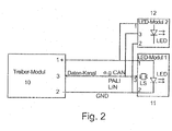
- Fig. 2 shows an embodiment of the device according to the invention with two LED modules (LED module 11, LED module 21) and a driver module 10th
- This device has a driver module 10, and an LED module 10 controlled by the driver module 10 with at least one LED 5.
- the driver module 10 has a first terminal, via which the LED module 11 connected thereto can be supplied with power by the driver module 10. This current is used to power the LED 5. Furthermore, the driver module 10 has a second terminal, which is preferably present as a ground connection (GND).
- GND ground connection
- the LED module 11 has a first terminal 1, via which the LED module is supplied by the driver module with a current and via a second terminal 2, preferably as a ground connection. There may be several LEDs 5 on a common LED module 11.
- the second terminal 2 can also form a virtual ground for the LED module 11, this means that this can form a local ground reference point for the LED module 11, wherein this local ground reference point does not have to be the mass of the driver module 10.
- this local ground reference point does not have to be the mass of the driver module 10.
- the second terminal 2 on the driver module 10 is not directly connected to ground, however, the associated second terminal 2 on the LED module 11 may act as a local ground when measurements on the LED module 11 with respect to done on this point.
- the LED module 11 and the driver module 10 have a third terminal 3, which is designed as a data channel.
- the terminals for the data channel from the LED module 11 and the driver module 10 are connected to each other, on the data channel is a voltage which is supplied by the driver module 10.
- the terminals of the driver module 10 and the LED module 11 are connected via the wiring 4. It is thus a connection for feeding the LED next to a ground connection and a data channel available.
- the LED module 11 is configured to short the voltage on the data channel for sending information. This can be done for example by a switch S1, which briefly closes the third terminal (data channel) to the second terminal (local ground connection (GND)) short.
- a switch S1 which briefly closes the third terminal (data channel) to the second terminal (local ground connection (GND)) short.
- the information sent by the LED module 11 contains information about a parameter of the LED module 11 or the status of the LED module 11.
- the driver module 10 according to the information sent by the LED module 11 to adjust its operation and For example, adjust the current accordingly, with which the LED module 11 is fed via the first terminal 1.
- the voltage on the data channel is used to supply a logic circuit (LS) on the LED module 11.
- the logic circuit may include, for example, a microcontroller that can monitor the voltage on the data channel and also control the transmission of a signal on the data channel.
- the logic circuit can drive a switch S1 which briefly closes the third terminal (data channel) to the second terminal (local ground connection (GND)).
- the voltage may be used on the data channel to power a sensor S disposed on the LED module 11 or connected to the LED module 11.
- the information sent by the LED module 11 may include information about the status of the sensor S or a signal detected by the sensor S.
- An address information can be transmitted via the data channel. In this way, when connecting a plurality of LED modules to a driver module 10, the individual LED modules can be identified and the LED modules can individually and selectively give feedback (send specific information).
- the information from the LED module 11 may be sent upon request by the driver module 10.
- the driver module 10 may also supply a voltage to the data channel (terminal 3) when the LED module 11 is not powered via the first terminal 1 from the driver module 10 with a current.
- the LED module 11 may also send information when the LED module 11 is not powered by the driver module 10 via the first terminal 1.
- the data channel 3 can also be powered in a standby mode by the driver module 10 with a voltage and communication between the LED module 11 and the driver module 10 is possible in this standby mode.
- the LED module 11 may have a memory that can be read by the driver module 10 via the data channel.
- the driver module 10 may be configured to monitor the voltage at its output for the data channel (terminal 3) and a change in the voltage at that output may be evaluated as transmission of information. This evaluation of the voltage at the third terminal 3 (data channel) can thus be used to receive information sent by the LED module 11.
- the driver module 10 may temporarily lower the voltage at its output for the data channel, preferably in the form of a pulse modulated signal to send information to the LED module 11.
- the driver module 10 can regularly read the memory of the LED module 11 and after the replacement of the LED module 11, the read memory information in the memory of the new LED module 11 are stored.
- the signaling for reading the memory on the LED module 11 can be done by the user by a switching sequence on the supply voltage, a digital control command or by other signaling.
- the driver module 10 can forward the information stored in the memory after reading from an LED module 11 via the data channel also to other LED modules.
- the data channel can be designed, for example, for a communication between LED module 11 and driver module 10 in accordance with an existing protocol such as DALI, LJN or CAN or another defined protocol.
- the defined protocol may also be a specific protocol for the exchange of data between LED modules and driver modules.
- the driver module 10 may power a plurality of LED modules via the same first power supply terminal 1 and exchange information with a plurality of LED modules via the same third terminal 3 for the data channel.
- one or more LED modules 11, 12 can be switched off by transmitting a corresponding switch-off information to these LED modules 11, 12 via the data channel, and these then interrupt the current through the LED.
- the sensor S may be a color sensor (eg CCD sensor or a photodiode with color filter).
- the color sensor may be placed so that it can receive a portion of the light emitted by the LED modules.
- the color sensor may be placed so that it is shielded from ambient light and can receive only light emitted by the LED modules.
- the sensor S can also be placed on the reflector of the LED lamp.
- the sensor S may be placed so that it directly or indirectly receives the light of the LED of the LED module.
- the sensor S may be a brightness sensor (eg a photodiode).
- the sensor S may be an ambient light sensor or an artificial light sensor.
- the sensor S for example an artificial light sensor, may be placed so that it is sealed off from ambient light and can only receive light emitted by the LED modules.
- the sensor S may be placed so that it directly or indirectly receives the light of the LED of the LED module.
- the sensor S preferably as an ambient light sensor, may be placed so that it can only receive ambient light and is shielded from light emitted by the LED modules.
- Such a partition can be achieved for example by a color filter or by a physical separation such as a kind of partition between LED and sensor S.
- the sensor S can also be placed on the reflector of the LED lamp.
- the sensor S may also be a presence sensor or motion sensor. Additionally or alternatively, the sensor S may also be a temperature sensor.
- the sensor S can also be formed by a combination of several different sensors.
- a plurality of sensors can be located in a housing, which are evaluated by common electronics (also possible as a multi-chip arrangement).
- an infrared sensor may be present to receive control signals of an infrared remote control.
- a radio receiver may be present to receive control signals of a wireless control device such as a smartphone with a radio transmitter (eg Bluetooth, Ziogbee or WLAN) or a wireless light control transmitter (eg wireless DALI).
- a radio transmitter eg Bluetooth, Ziogbee or WLAN
- a wireless light control transmitter eg wireless DALI
- the driver module 10 can, according to the received information Adjust the operation of the LED module 11. For example, it may increase the current through the LED when a presence sensor or motion sensor detects a person, or it may lower the current when the ambient light exceeds a predetermined minimum brightness.
- a temperature sensor is present on the LED module 11, it can also transmit an excess temperature as information over the data channel to the driver module 10 and the driver module 10 can then lower or interrupt the current through the LED.
- the brightness of the LED module 11 can also be controlled via this sensor S by the sensor S receiving the received control signal from the LED module 11 over the data Channel transmitted to the driver module 10 and the driver module 10 then according to the supply of the LED module via the first terminal 1 adapts, for example, according to the specification of the control signal adjusts the current for the LED.
- a control signal such as an infrared sensor or radio receiver
- the LED module 11 may also be arranged an art load connected to the terminal 3 for the data channel, this art load loading the data channel and this loading by the driver module 10 as information from the LED module 11 can be evaluated.
- the art load may preferably be formed by a passive component, preferably a resistor.
- the value of the artificial load in this case represents a coding of a characteristic value of the LED module 11, for example an operating parameter or the color or dominant wavelength of the LED module 11.
- the value of the artificial load may include information about the nominal operating current of the LED module. Play module 11.
- the resistance of the art load may be in a linearly proportional or inversely proportional relationship to the nominal operating current of the LED module 11, or alternatively may be in an exponential or logarithmic relationship to the nominal operating current of the LED module 11.
- the driver module 10 may be configured to receive both analog information, preferably due to exposure to a plastic load, as well as digital information, preferably by pulse width modulated signals, from the LED module 11.
- a luminaire with LED comprising one can be constructed according to the invention
- a method for operating LEDs is also possible, wherein an LED module 11 with at least one LED is driven by a driver module 10, and a data channel for transmitting information via the LED module 11 is provided, wherein the Data channel is supplied by the driver module 10 with a voltage and the LED module 11 is adapted to short-circuit the voltage on the data channel for transmitting information.
- the driver module 10 feeds the terminal 3 and thus the data channel only after starting or switching on with a voltage to read within a start phase information from the LED module 11 via the data channel, and after the start phase turn off the voltage at the third terminal and thus disable the data channel again.
- the data channel is repeatedly reactivated briefly after a certain time to read again information from the LED module 11 or to start a query or certain information or even brightness commands or other instructions to send the LED module 11. It would also be possible to monitor in this way an aging or running time of the LED module 11. The information from the LED module 11 may be sent upon request by the driver module 10.
- the data channel can also be powered in a stand-by mode by the driver module 10 with a voltage and communication between the LED module 11 and driver module 10 may also be possible in this stand-by mode, that is, for example the LEDs are off.
- a further monitoring using one or more sensors of the LED module 11 also take place when the LED of the LED module 11 are turned off and no voltage is applied to the first input 1 for feeding the LED 5.
- the LED module 11 may have a memory for storing information about the LED module 11, wherein the information in the memory can optionally also be changed.
- the information in the memory can be changed based on a calibration measurement.
- the information in the memory can be changed by a correction factor.
- the correction factor may depend on the aging or the operating time of the LED module.
- the correction factor may be dependent on the temperature of the LED module.
- the driver module 10 may include a switching regulator, such as an AC-DC converter.
- the driver module 10 may include a PFC (Active Power Factor Correction Circuit).
- the driver module 10 may have a potential separation.
- the driver module 10 may include a floating switch regulator such as an isolated flyback converter or an isolated half-bridge converter.
- the driver module 10 can optionally have an interface for user control, for example for adjusting the brightness. This interface can be designed, for example, for connection to a lighting control system such as DALI or DMX.
Landscapes
- Engineering & Computer Science (AREA)
- Life Sciences & Earth Sciences (AREA)
- Food Science & Technology (AREA)
- Computer Networks & Wireless Communication (AREA)
- Signal Processing (AREA)
- Circuit Arrangement For Electric Light Sources In General (AREA)
- Control Of Indicators Other Than Cathode Ray Tubes (AREA)
Claims (16)
- Dispositif de commande de LED, comprenant :un module pilote (10), le module pilote comprenant un régulateur de commutation, un circuit de correction de facteur de puissance, une séparation de potentiel et/ou une interface de commande par l'utilisateur ; etun module LED (11), avec au moins une LED (5), commandé par le module pilote (10) ;le module LED (11) étant alimenté en courant par l'intermédiaire d'un branchement (1) par le module pilote (10) et un deuxième branchement (2) étant prévu, de préférence en tant que liaison avec la masse (GND) ;le module LED (11) étant relié au module pilote (10) par l'intermédiaire d'un troisième branchement (3), qui est conçu comme un canal de données, une tension étant appliquée au canal de données, qui est alimentée par le module pilote (10) ;le module LED (11) étant conçu pour envoyer des informations, les informations envoyées par le module LED (11) contenant un renseignement concernant un paramètre du module LED (11) ou le statut du module LED (11), le module LED (11) étant conçu, pour l'envoi des informations, pour court-circuiter la tension au niveau du canal de données ; etla tension au niveau du canal de données étant utilisée pour alimenter un circuit logique sur le module LED (11) ;caractérisé en ce quele dispositif est conçu pour couper la tension traversant le module pilote (10) au niveau du canal de données après une phase de démarrage du module pilote (10).
- Dispositif de commande de LED selon la revendication 1,
caractérisé en ce que
la tension au niveau du canal de connées est utilisé en outre pour alimenter un capteur, qui est disposé sur le module LED (11) et qui est relié avec le module LED (11). - Dispositif de commande de LED selon la revendication 2,
caractérisé en ce que
les informations envoyées par le module LED (11) contiennent un renseignement concernant le statut du capteur ou un signal détecté par le capteur (S). - Dispositif de commande de LED selon l'une des revendications précédentes,
caractérisé en ce que
une information d'adresse est transmise par l'intermédiaire du canal de données. - Dispositif de commande de LED selon l'une des revendications précédentes,
caractérisé en ce que
le module pilote (10) applique également une tension au canal de données, lorsque le module LED (11) n'est pas alimenté en courant par l'intermédiaire du premier branchement par le module pilote (10). - Dispositif de commande de LED selon l'une des revendications précédentes,
caractérisé en ce que
le module LED (11) envoie également des informations lorsque le module LED (11) n'est pas alimenté en courant par l'intermédiaire du premier branchement (1) par le module pilote (10). - Dispositif de commande de LED selon l'une des revendications précédentes,
caractérisé en ce que
le module LED (11) dispose d'une mémoire, qui peut être lue par le module pilote (10) par l'intermédiaire du canal de données. - Dispositif de commande de LED selon l'une des revendications précédentes,
caractérisé en ce que
le module pilote (10) est conçu pour surveiller la tension à sa sortie (3) pour le canal de données et analyser une modification de la tension à cette sortie (3) en tant que transmission d'informations. - Dispositif de commande de LED selon l'une des revendications précédentes,
caractérisé en ce que
le module pilote (10) peut abaisser brièvement la tension à sa sortie (3) pour le canal de données,
de préférence sous la forme d'un signal modulé par impulsions, afin d'envoyer une information au module LED (11). - Dispositif de commande de LED selon la revendication 7,
caractérisé en ce que
le module pilote (10) peut lire régulièrement la mémoire du module LED (11) et, après le remplacement du module LED, les infirmations lues dans la mémoire peuvent être enregistrées dans la mémoire du nouveau module LED. - Dispositif de commande de LED selon l'une des revendications précédentes,
caractérisé en ce que
le module pilote (10) peut alimenter en courant plusieurs modules LED par l'intermédiaire du même branchement (1) pour l'alimentation en courant et peut échanger des infirmations avec plusieurs modules LED par l'intermédiaire du même branchement (3) pour le canal de données. - Dispositif de commande de LED selon l'une des revendications précédentes,
caractérisé en ce que
un ou plusieurs modules LED peuvent être arrêtés en transmettant par l'intermédiaire du canal de données une information d'arrêt correspondante à ces modules LED et ceux-ci interrompent alors le courant à travers les LED (5). - Dispositif de commande de LED selon la revendication 2,
caractérisé en ce que
le capteur (S) est un capteur de couleur, par exemple un capteur CCD. - Dispositif de commande de LED selon la revendication 13,
caractérisé en ce que
le capteur de couleur est positionné de façon à ce qu'il puisse recevoir une partie de la lumière émise par les modules LED. - Dispositif de commande de LED selon l'une des revendications précédentes,
caractérisé en ce que
sur le module LED (11) est disposée une charge factice qui est reliée avec le branchement (3) pour le canal de données, cette charge factice sollicitant le canal de données et cette charge étant analysée par le module pilote (10) comme une information provenant du module LED (11). - Procédé de commande de LED comprenant les étapes suivantes :commande d'un module LED (11) avec au moins une LED (5) par un module pilote (10), qui comprend un régulateur de commutation, un circuit de correction de facteur de puissance, une séparation de potentiel et/ou une interface de commande par l'utilisateur, un canal de données étant prévu pour la transmission d'informations par l'intermédiaire du module LED (11) ;alimentation du module LED (11) en courant par le module pilote (10) par l'intermédiaire d'un premier branchement (1), le module LED comprenant un deuxième branchement (2), de préférence sous la forme d'une liaison à la masse (GND) et étant relié avec le module pilote (10) par l'intermédiaire d'un troisième branchement (3) qui est conçu comme le canal de données ;alimentation du canal de données par le module pilote (10) avec une tension ;utilisation de la tension appliquée au canal de données pour alimenter un circuit logique sur le module LED (11) et court-circuitage de la tension appliquée au canal de données pour l'envoi d'informations à l'aide du module LED (11) ;les informations envoyées par le module LED (11) contenant un renseignement concernant un paramètre du module LED (11) ou le statut du module LED (11),caractérisé parl'arrêt de la tension appliquée par le module pilote (10) au canal de données après une phase de démarrage du module pilote (10).
Applications Claiming Priority (2)
| Application Number | Priority Date | Filing Date | Title |
|---|---|---|---|
| ATGM29/2013U AT14580U1 (de) | 2013-01-31 | 2013-01-31 | Vorrichtung zum Betreiben von LEDs |
| PCT/AT2014/000022 WO2014117193A2 (fr) | 2013-01-31 | 2014-01-31 | Dispositif servant à faire fonctionner des del |
Publications (2)
| Publication Number | Publication Date |
|---|---|
| EP2952065A2 EP2952065A2 (fr) | 2015-12-09 |
| EP2952065B1 true EP2952065B1 (fr) | 2018-08-08 |
Family
ID=51263066
Family Applications (1)
| Application Number | Title | Priority Date | Filing Date |
|---|---|---|---|
| EP14712184.2A Active EP2952065B1 (fr) | 2013-01-31 | 2014-01-31 | Dispositif et procédé servant à faire fonctionner des del |
Country Status (5)
| Country | Link |
|---|---|
| US (1) | US9743485B2 (fr) |
| EP (1) | EP2952065B1 (fr) |
| CN (1) | CN104956772A (fr) |
| AT (1) | AT14580U1 (fr) |
| WO (1) | WO2014117193A2 (fr) |
Families Citing this family (5)
| Publication number | Priority date | Publication date | Assignee | Title |
|---|---|---|---|---|
| US9544972B2 (en) * | 2014-11-10 | 2017-01-10 | General Electric Company | Gate voltage threshold turn off for maintaining voltage supply during standby mode of a lighting system |
| DE102016221772A1 (de) * | 2016-11-07 | 2018-05-09 | Bayerische Motoren Werke Aktiengesellschaft | Beleuchtungsvorrichtung und Beleuchtungssystem für ein Kraftfahrzeug sowie Verfahren zum Betreiben eines Beleuchtungssystems für ein Kraftfahrzeug |
| DE102016226016A1 (de) * | 2016-12-22 | 2018-06-28 | Osram Gmbh | SCHALTUNGSANORDNUNG ZUM BETREIBEN VON LICHTQUELLEN UND SENSOR ZUM ANSCHLIEßEN AN EINE SCHALTUNGSANORDNUNG |
| DE102018209561B3 (de) | 2018-06-14 | 2019-09-26 | H4X E.U. | Ansteuervorrichtung für eine led-leuchte und verfahren zur ansteuerung einer led-leuchte |
| JP2020047508A (ja) * | 2018-09-20 | 2020-03-26 | パナソニックIpマネジメント株式会社 | 照明システム及び照明システムの設定方法 |
Citations (1)
| Publication number | Priority date | Publication date | Assignee | Title |
|---|---|---|---|---|
| DE102010031242A1 (de) * | 2010-03-19 | 2011-09-22 | Tridonic Ag | LED-Beleuchtungssystem mit Betriebsdatenspeicher |
Family Cites Families (23)
| Publication number | Priority date | Publication date | Assignee | Title |
|---|---|---|---|---|
| DE19852350A1 (de) | 1998-11-13 | 2000-05-18 | Hella Kg Hueck & Co | Diagnosesystem für das Vorschaltgerät einer Hochdruckgasentladungslampe in einem Kraftfahrzeug |
| DE19852351A1 (de) | 1998-11-13 | 2000-05-18 | Hella Kg Hueck & Co | Diagnosesystem für eine LED-Leuchte in einem Kraftfahrzeug |
| DE102004027932A1 (de) | 2004-06-08 | 2005-12-29 | Volkswagen Ag | Beleuchtungseinrichtung für ein Fahrzeug umfassend einen Sensor |
| WO2006056066A1 (fr) | 2004-11-29 | 2006-06-01 | Tir Systems Ltd. | Unite d'eclairage modulaire integree |
| US8829799B2 (en) * | 2006-03-28 | 2014-09-09 | Wireless Environment, Llc | Autonomous grid shifting lighting device |
| US8994276B2 (en) * | 2006-03-28 | 2015-03-31 | Wireless Environment, Llc | Grid shifting system for a lighting circuit |
| US8323189B2 (en) * | 2006-05-12 | 2012-12-04 | Bao Tran | Health monitoring appliance |
| US20090322251A1 (en) * | 2006-06-27 | 2009-12-31 | Koninklijke Philips Electronics N.V. | Large area lighting |
| WO2008061560A1 (fr) | 2006-11-22 | 2008-05-29 | Patent-Treuhand-Gesellschaft für elektrische Glühlampen mbH | Luminaire coloré et procédé de génération d'une lumière colorée de localisation chromatique prédéfinie grâce à un luminaire |
| US8400061B2 (en) * | 2007-07-17 | 2013-03-19 | I/O Controls Corporation | Control network for LED-based lighting system in a transit vehicle |
| US8258702B2 (en) * | 2008-05-21 | 2012-09-04 | Ford Global Technologies, Llc | Ambient LED lighting system and method |
| US8476788B2 (en) * | 2008-09-27 | 2013-07-02 | Witricity Corporation | Wireless energy transfer with high-Q resonators using field shaping to improve K |
| US20120119698A1 (en) * | 2008-09-27 | 2012-05-17 | Aristeidis Karalis | Wireless energy transfer for vehicles |
| US8461722B2 (en) * | 2008-09-27 | 2013-06-11 | Witricity Corporation | Wireless energy transfer using conducting surfaces to shape field and improve K |
| US8587153B2 (en) * | 2008-09-27 | 2013-11-19 | Witricity Corporation | Wireless energy transfer using high Q resonators for lighting applications |
| US20100176733A1 (en) * | 2009-01-14 | 2010-07-15 | Purespectrum, Inc. | Automated Dimming Methods and Systems For Lighting |
| GB2473142B (en) * | 2009-09-01 | 2017-03-01 | Fisher Rosemount Systems Inc | Integrated bus controller and power supply device for use in a process control system |
| AU2010326847A1 (en) * | 2009-12-04 | 2012-06-21 | Osram Ag | A method for controlling the operation of an electronic converter, and a corresponding electronic converter, lighting system and software product |
| WO2011087684A1 (fr) | 2010-01-13 | 2011-07-21 | Masco Corporation | Systèmes de commande basse tension et procédés associés |
| EP2375858A1 (fr) | 2010-04-07 | 2011-10-12 | polynom ag | Circuit électronique pour la mesure de la luminosité de diodes luminescentes utilisées dans une lampe de secours |
| DE102010050747A1 (de) | 2010-11-08 | 2012-05-10 | Vishay Electronic Gmbh | Schaltungsanordnung zum Betreiben einer Leuchtdiode |
| GB2491550A (en) * | 2011-01-17 | 2012-12-12 | Radiant Res Ltd | A hybrid power control system using dynamic power regulation to increase the dimming dynamic range and power control of solid-state illumination systems |
| DE102011113080A1 (de) * | 2011-02-18 | 2012-08-23 | Volkswagen Aktiengesellschaft | Verfahren und Vorrichtung zur Diagnose von Leuchtmitteln in einem Fahrzeug |
-
2013
- 2013-01-31 AT ATGM29/2013U patent/AT14580U1/de not_active IP Right Cessation
-
2014
- 2014-01-31 EP EP14712184.2A patent/EP2952065B1/fr active Active
- 2014-01-31 CN CN201480006592.6A patent/CN104956772A/zh active Pending
- 2014-01-31 WO PCT/AT2014/000022 patent/WO2014117193A2/fr not_active Ceased
- 2014-01-31 US US14/761,531 patent/US9743485B2/en not_active Expired - Fee Related
Patent Citations (1)
| Publication number | Priority date | Publication date | Assignee | Title |
|---|---|---|---|---|
| DE102010031242A1 (de) * | 2010-03-19 | 2011-09-22 | Tridonic Ag | LED-Beleuchtungssystem mit Betriebsdatenspeicher |
Also Published As
| Publication number | Publication date |
|---|---|
| AT14580U1 (de) | 2016-01-15 |
| WO2014117193A2 (fr) | 2014-08-07 |
| US20150351173A1 (en) | 2015-12-03 |
| US9743485B2 (en) | 2017-08-22 |
| EP2952065A2 (fr) | 2015-12-09 |
| CN104956772A (zh) | 2015-09-30 |
| WO2014117193A3 (fr) | 2015-01-29 |
Similar Documents
| Publication | Publication Date | Title |
|---|---|---|
| EP2510747B1 (fr) | Lampes à diodes asservies pour rénovation et système d'éclairage avec lampe à diodes | |
| EP2952065B1 (fr) | Dispositif et procédé servant à faire fonctionner des del | |
| EP3270663B1 (fr) | Module led remplaçable ayant une mémoire et alimentation en courant pour cela | |
| EP3069573B1 (fr) | Module de del, convertisseur de del et procédé permettant de faire fonctionner au moins une diode electroluminescente | |
| DE102017115152A1 (de) | Signalgeber und beleuchtungssystem | |
| DE102015211454A1 (de) | Sensorspeisung mit einem Konstantstrom-Konverter für Leuchtmittel | |
| DE102017115133A1 (de) | Signalempfangsvorrichtung, Signalübertragungsvorrichtung, Lichtsystem, Beleuchtungsvorrichtung und Beleuchtungssystem | |
| EP2952061B1 (fr) | Dispositif de fonctionnement de del | |
| WO2017080828A1 (fr) | Système d'éclairage et procédé d'alimentation d'un module de transmission sans fil | |
| EP3222064B1 (fr) | Moyen d'éclairage, système et procédé de communication | |
| DE102014202720A1 (de) | Beleuchtungssystem | |
| EP2335454A2 (fr) | Dispositif pour faire fonctionner des del | |
| WO2016065382A1 (fr) | Procédé de commande pour un dispositif de fonctionnement de moyen d'éclairage | |
| WO2017157848A1 (fr) | Appareil d'exploitation très fonctionnel | |
| WO2013023230A2 (fr) | Procédé d'addressage d'appareils d'actionnement d'éléments luminescents | |
| EP3182800B1 (fr) | Appareil de commande pour un système d'éclairage | |
| EP3637959B1 (fr) | Composant semi-conducteur | |
| DE102015207331A1 (de) | Verfahren zur Adressierung von Leuchtmittelbetriebsgeräten | |
| DE212014000113U1 (de) | Beleuchtungssystem zur Ansteuerung von Leuchtmittelbetriebsgeräten | |
| EP2425683B1 (fr) | Interface pour installation d'éclairage | |
| EP3021644A1 (fr) | Appareil de commande a del sans fil programmable | |
| DE112012004148B4 (de) | Verfahren und Beleuchtungssystem zur Ansteuerung von zumindest zwei unabhängig voneinander ansteuerbaren Leuchtdioden | |
| EP2510750B1 (fr) | Circuit d'excitation pour une del | |
| WO2011003916A1 (fr) | Appareil destiné à faire fonctionner un élément lumineux | |
| DE102014223730A1 (de) | Leuchtmittel, System und Kommunikationsverfahren |
Legal Events
| Date | Code | Title | Description |
|---|---|---|---|
| PUAI | Public reference made under article 153(3) epc to a published international application that has entered the european phase |
Free format text: ORIGINAL CODE: 0009012 |
|
| 17P | Request for examination filed |
Effective date: 20150710 |
|
| AK | Designated contracting states |
Kind code of ref document: A2 Designated state(s): AL AT BE BG CH CY CZ DE DK EE ES FI FR GB GR HR HU IE IS IT LI LT LU LV MC MK MT NL NO PL PT RO RS SE SI SK SM TR |
|
| AX | Request for extension of the european patent |
Extension state: BA ME |
|
| RIN1 | Information on inventor provided before grant (corrected) |
Inventor name: NESENSOHN, CHRISTIAN Inventor name: SCHOENBERGER, JOHN Inventor name: MOOSMANN, FLORIAN Inventor name: MARENT, GUENTER Inventor name: LOCHMANN, FRANK Inventor name: PACHLER, PETER Inventor name: HORN, FRANK Inventor name: RIEMER, STEFFEN Inventor name: DUENSER, MATHIAS Inventor name: JUEN, REINHOLD Inventor name: KLEBER, NORBERT |
|
| DAX | Request for extension of the european patent (deleted) | ||
| STAA | Information on the status of an ep patent application or granted ep patent |
Free format text: STATUS: EXAMINATION IS IN PROGRESS |
|
| 17Q | First examination report despatched |
Effective date: 20170104 |
|
| REG | Reference to a national code |
Ref country code: DE Ref legal event code: R079 Ref document number: 502014009129 Country of ref document: DE Free format text: PREVIOUS MAIN CLASS: H05B0037020000 Ipc: H05B0033080000 |
|
| GRAP | Despatch of communication of intention to grant a patent |
Free format text: ORIGINAL CODE: EPIDOSNIGR1 |
|
| STAA | Information on the status of an ep patent application or granted ep patent |
Free format text: STATUS: GRANT OF PATENT IS INTENDED |
|
| RIC1 | Information provided on ipc code assigned before grant |
Ipc: H05B 33/08 20060101AFI20180426BHEP Ipc: A21C 3/04 20060101ALI20180426BHEP Ipc: H05B 37/02 20060101ALI20180426BHEP |
|
| INTG | Intention to grant announced |
Effective date: 20180524 |
|
| GRAS | Grant fee paid |
Free format text: ORIGINAL CODE: EPIDOSNIGR3 |
|
| GRAA | (expected) grant |
Free format text: ORIGINAL CODE: 0009210 |
|
| STAA | Information on the status of an ep patent application or granted ep patent |
Free format text: STATUS: THE PATENT HAS BEEN GRANTED |
|
| AK | Designated contracting states |
Kind code of ref document: B1 Designated state(s): AL AT BE BG CH CY CZ DE DK EE ES FI FR GB GR HR HU IE IS IT LI LT LU LV MC MK MT NL NO PL PT RO RS SE SI SK SM TR |
|
| REG | Reference to a national code |
Ref country code: GB Ref legal event code: FG4D Free format text: NOT ENGLISH |
|
| REG | Reference to a national code |
Ref country code: CH Ref legal event code: EP Ref country code: AT Ref legal event code: REF Ref document number: 1028598 Country of ref document: AT Kind code of ref document: T Effective date: 20180815 |
|
| REG | Reference to a national code |
Ref country code: IE Ref legal event code: FG4D Free format text: LANGUAGE OF EP DOCUMENT: GERMAN |
|
| REG | Reference to a national code |
Ref country code: DE Ref legal event code: R096 Ref document number: 502014009129 Country of ref document: DE |
|
| REG | Reference to a national code |
Ref country code: NL Ref legal event code: MP Effective date: 20180808 |
|
| REG | Reference to a national code |
Ref country code: LT Ref legal event code: MG4D |
|
| PG25 | Lapsed in a contracting state [announced via postgrant information from national office to epo] |
Ref country code: LT Free format text: LAPSE BECAUSE OF FAILURE TO SUBMIT A TRANSLATION OF THE DESCRIPTION OR TO PAY THE FEE WITHIN THE PRESCRIBED TIME-LIMIT Effective date: 20180808 Ref country code: IS Free format text: LAPSE BECAUSE OF FAILURE TO SUBMIT A TRANSLATION OF THE DESCRIPTION OR TO PAY THE FEE WITHIN THE PRESCRIBED TIME-LIMIT Effective date: 20181208 Ref country code: RS Free format text: LAPSE BECAUSE OF FAILURE TO SUBMIT A TRANSLATION OF THE DESCRIPTION OR TO PAY THE FEE WITHIN THE PRESCRIBED TIME-LIMIT Effective date: 20180808 Ref country code: PL Free format text: LAPSE BECAUSE OF FAILURE TO SUBMIT A TRANSLATION OF THE DESCRIPTION OR TO PAY THE FEE WITHIN THE PRESCRIBED TIME-LIMIT Effective date: 20180808 Ref country code: NL Free format text: LAPSE BECAUSE OF FAILURE TO SUBMIT A TRANSLATION OF THE DESCRIPTION OR TO PAY THE FEE WITHIN THE PRESCRIBED TIME-LIMIT Effective date: 20180808 Ref country code: BG Free format text: LAPSE BECAUSE OF FAILURE TO SUBMIT A TRANSLATION OF THE DESCRIPTION OR TO PAY THE FEE WITHIN THE PRESCRIBED TIME-LIMIT Effective date: 20181108 Ref country code: FI Free format text: LAPSE BECAUSE OF FAILURE TO SUBMIT A TRANSLATION OF THE DESCRIPTION OR TO PAY THE FEE WITHIN THE PRESCRIBED TIME-LIMIT Effective date: 20180808 Ref country code: GR Free format text: LAPSE BECAUSE OF FAILURE TO SUBMIT A TRANSLATION OF THE DESCRIPTION OR TO PAY THE FEE WITHIN THE PRESCRIBED TIME-LIMIT Effective date: 20181109 Ref country code: NO Free format text: LAPSE BECAUSE OF FAILURE TO SUBMIT A TRANSLATION OF THE DESCRIPTION OR TO PAY THE FEE WITHIN THE PRESCRIBED TIME-LIMIT Effective date: 20181108 Ref country code: SE Free format text: LAPSE BECAUSE OF FAILURE TO SUBMIT A TRANSLATION OF THE DESCRIPTION OR TO PAY THE FEE WITHIN THE PRESCRIBED TIME-LIMIT Effective date: 20180808 |
|
| PG25 | Lapsed in a contracting state [announced via postgrant information from national office to epo] |
Ref country code: HR Free format text: LAPSE BECAUSE OF FAILURE TO SUBMIT A TRANSLATION OF THE DESCRIPTION OR TO PAY THE FEE WITHIN THE PRESCRIBED TIME-LIMIT Effective date: 20180808 Ref country code: LV Free format text: LAPSE BECAUSE OF FAILURE TO SUBMIT A TRANSLATION OF THE DESCRIPTION OR TO PAY THE FEE WITHIN THE PRESCRIBED TIME-LIMIT Effective date: 20180808 Ref country code: AL Free format text: LAPSE BECAUSE OF FAILURE TO SUBMIT A TRANSLATION OF THE DESCRIPTION OR TO PAY THE FEE WITHIN THE PRESCRIBED TIME-LIMIT Effective date: 20180808 |
|
| PG25 | Lapsed in a contracting state [announced via postgrant information from national office to epo] |
Ref country code: RO Free format text: LAPSE BECAUSE OF FAILURE TO SUBMIT A TRANSLATION OF THE DESCRIPTION OR TO PAY THE FEE WITHIN THE PRESCRIBED TIME-LIMIT Effective date: 20180808 Ref country code: CZ Free format text: LAPSE BECAUSE OF FAILURE TO SUBMIT A TRANSLATION OF THE DESCRIPTION OR TO PAY THE FEE WITHIN THE PRESCRIBED TIME-LIMIT Effective date: 20180808 Ref country code: IT Free format text: LAPSE BECAUSE OF FAILURE TO SUBMIT A TRANSLATION OF THE DESCRIPTION OR TO PAY THE FEE WITHIN THE PRESCRIBED TIME-LIMIT Effective date: 20180808 Ref country code: ES Free format text: LAPSE BECAUSE OF FAILURE TO SUBMIT A TRANSLATION OF THE DESCRIPTION OR TO PAY THE FEE WITHIN THE PRESCRIBED TIME-LIMIT Effective date: 20180808 Ref country code: EE Free format text: LAPSE BECAUSE OF FAILURE TO SUBMIT A TRANSLATION OF THE DESCRIPTION OR TO PAY THE FEE WITHIN THE PRESCRIBED TIME-LIMIT Effective date: 20180808 |
|
| REG | Reference to a national code |
Ref country code: DE Ref legal event code: R097 Ref document number: 502014009129 Country of ref document: DE |
|
| PG25 | Lapsed in a contracting state [announced via postgrant information from national office to epo] |
Ref country code: SM Free format text: LAPSE BECAUSE OF FAILURE TO SUBMIT A TRANSLATION OF THE DESCRIPTION OR TO PAY THE FEE WITHIN THE PRESCRIBED TIME-LIMIT Effective date: 20180808 Ref country code: DK Free format text: LAPSE BECAUSE OF FAILURE TO SUBMIT A TRANSLATION OF THE DESCRIPTION OR TO PAY THE FEE WITHIN THE PRESCRIBED TIME-LIMIT Effective date: 20180808 Ref country code: SK Free format text: LAPSE BECAUSE OF FAILURE TO SUBMIT A TRANSLATION OF THE DESCRIPTION OR TO PAY THE FEE WITHIN THE PRESCRIBED TIME-LIMIT Effective date: 20180808 |
|
| PGFP | Annual fee paid to national office [announced via postgrant information from national office to epo] |
Ref country code: AT Payment date: 20190129 Year of fee payment: 6 |
|
| PLBE | No opposition filed within time limit |
Free format text: ORIGINAL CODE: 0009261 |
|
| STAA | Information on the status of an ep patent application or granted ep patent |
Free format text: STATUS: NO OPPOSITION FILED WITHIN TIME LIMIT |
|
| 26N | No opposition filed |
Effective date: 20190509 |
|
| PG25 | Lapsed in a contracting state [announced via postgrant information from national office to epo] |
Ref country code: MC Free format text: LAPSE BECAUSE OF FAILURE TO SUBMIT A TRANSLATION OF THE DESCRIPTION OR TO PAY THE FEE WITHIN THE PRESCRIBED TIME-LIMIT Effective date: 20180808 Ref country code: SI Free format text: LAPSE BECAUSE OF FAILURE TO SUBMIT A TRANSLATION OF THE DESCRIPTION OR TO PAY THE FEE WITHIN THE PRESCRIBED TIME-LIMIT Effective date: 20180808 |
|
| REG | Reference to a national code |
Ref country code: CH Ref legal event code: PL |
|
| PG25 | Lapsed in a contracting state [announced via postgrant information from national office to epo] |
Ref country code: LU Free format text: LAPSE BECAUSE OF NON-PAYMENT OF DUE FEES Effective date: 20190131 |
|
| REG | Reference to a national code |
Ref country code: BE Ref legal event code: MM Effective date: 20190131 |
|
| REG | Reference to a national code |
Ref country code: DE Ref legal event code: R084 Ref document number: 502014009129 Country of ref document: DE |
|
| REG | Reference to a national code |
Ref country code: IE Ref legal event code: MM4A |
|
| REG | Reference to a national code |
Ref country code: DE Ref legal event code: R079 Ref document number: 502014009129 Country of ref document: DE Free format text: PREVIOUS MAIN CLASS: H05B0033080000 Ipc: H05B0045000000 |
|
| PG25 | Lapsed in a contracting state [announced via postgrant information from national office to epo] |
Ref country code: BE Free format text: LAPSE BECAUSE OF NON-PAYMENT OF DUE FEES Effective date: 20190131 |
|
| PG25 | Lapsed in a contracting state [announced via postgrant information from national office to epo] |
Ref country code: CH Free format text: LAPSE BECAUSE OF NON-PAYMENT OF DUE FEES Effective date: 20190131 Ref country code: LI Free format text: LAPSE BECAUSE OF NON-PAYMENT OF DUE FEES Effective date: 20190131 |
|
| PG25 | Lapsed in a contracting state [announced via postgrant information from national office to epo] |
Ref country code: IE Free format text: LAPSE BECAUSE OF NON-PAYMENT OF DUE FEES Effective date: 20190131 |
|
| PG25 | Lapsed in a contracting state [announced via postgrant information from national office to epo] |
Ref country code: TR Free format text: LAPSE BECAUSE OF FAILURE TO SUBMIT A TRANSLATION OF THE DESCRIPTION OR TO PAY THE FEE WITHIN THE PRESCRIBED TIME-LIMIT Effective date: 20180808 |
|
| PG25 | Lapsed in a contracting state [announced via postgrant information from national office to epo] |
Ref country code: PT Free format text: LAPSE BECAUSE OF FAILURE TO SUBMIT A TRANSLATION OF THE DESCRIPTION OR TO PAY THE FEE WITHIN THE PRESCRIBED TIME-LIMIT Effective date: 20181208 Ref country code: MT Free format text: LAPSE BECAUSE OF FAILURE TO SUBMIT A TRANSLATION OF THE DESCRIPTION OR TO PAY THE FEE WITHIN THE PRESCRIBED TIME-LIMIT Effective date: 20180808 |
|
| REG | Reference to a national code |
Ref country code: AT Ref legal event code: MM01 Ref document number: 1028598 Country of ref document: AT Kind code of ref document: T Effective date: 20200131 |
|
| PG25 | Lapsed in a contracting state [announced via postgrant information from national office to epo] |
Ref country code: AT Free format text: LAPSE BECAUSE OF NON-PAYMENT OF DUE FEES Effective date: 20200131 |
|
| PG25 | Lapsed in a contracting state [announced via postgrant information from national office to epo] |
Ref country code: CY Free format text: LAPSE BECAUSE OF FAILURE TO SUBMIT A TRANSLATION OF THE DESCRIPTION OR TO PAY THE FEE WITHIN THE PRESCRIBED TIME-LIMIT Effective date: 20180808 |
|
| PG25 | Lapsed in a contracting state [announced via postgrant information from national office to epo] |
Ref country code: HU Free format text: LAPSE BECAUSE OF FAILURE TO SUBMIT A TRANSLATION OF THE DESCRIPTION OR TO PAY THE FEE WITHIN THE PRESCRIBED TIME-LIMIT; INVALID AB INITIO Effective date: 20140131 |
|
| PGFP | Annual fee paid to national office [announced via postgrant information from national office to epo] |
Ref country code: FR Payment date: 20220126 Year of fee payment: 9 |
|
| PG25 | Lapsed in a contracting state [announced via postgrant information from national office to epo] |
Ref country code: MK Free format text: LAPSE BECAUSE OF FAILURE TO SUBMIT A TRANSLATION OF THE DESCRIPTION OR TO PAY THE FEE WITHIN THE PRESCRIBED TIME-LIMIT Effective date: 20180808 |
|
| P01 | Opt-out of the competence of the unified patent court (upc) registered |
Effective date: 20230530 |
|
| PG25 | Lapsed in a contracting state [announced via postgrant information from national office to epo] |
Ref country code: FR Free format text: LAPSE BECAUSE OF NON-PAYMENT OF DUE FEES Effective date: 20230131 |
|
| PGFP | Annual fee paid to national office [announced via postgrant information from national office to epo] |
Ref country code: DE Payment date: 20250129 Year of fee payment: 12 |
|
| PGFP | Annual fee paid to national office [announced via postgrant information from national office to epo] |
Ref country code: GB Payment date: 20250121 Year of fee payment: 12 |