EP2952070B1 - Méthode et appareil pour diriger un faisceau neutre - Google Patents
Méthode et appareil pour diriger un faisceau neutre Download PDFInfo
- Publication number
- EP2952070B1 EP2952070B1 EP14745537.2A EP14745537A EP2952070B1 EP 2952070 B1 EP2952070 B1 EP 2952070B1 EP 14745537 A EP14745537 A EP 14745537A EP 2952070 B1 EP2952070 B1 EP 2952070B1
- Authority
- EP
- European Patent Office
- Prior art keywords
- gas
- neutral
- cluster
- cluster ion
- gcib
- Prior art date
- Legal status (The legal status is an assumption and is not a legal conclusion. Google has not performed a legal analysis and makes no representation as to the accuracy of the status listed.)
- Not-in-force
Links
- 230000007935 neutral effect Effects 0.000 title claims description 169
- 238000000034 method Methods 0.000 title claims description 41
- 150000002500 ions Chemical class 0.000 claims description 135
- 238000010884 ion-beam technique Methods 0.000 claims description 50
- 230000001133 acceleration Effects 0.000 claims description 27
- 239000002245 particle Substances 0.000 claims description 22
- 238000010494 dissociation reaction Methods 0.000 claims description 12
- 230000005593 dissociations Effects 0.000 claims description 12
- 150000001875 compounds Chemical class 0.000 claims description 8
- 238000004519 manufacturing process Methods 0.000 claims description 5
- 239000007789 gas Substances 0.000 description 83
- 238000012545 processing Methods 0.000 description 70
- 239000000178 monomer Substances 0.000 description 61
- 238000004980 dosimetry Methods 0.000 description 28
- 238000005259 measurement Methods 0.000 description 22
- 230000008569 process Effects 0.000 description 16
- 230000007246 mechanism Effects 0.000 description 15
- 239000000463 material Substances 0.000 description 13
- 238000010438 heat treatment Methods 0.000 description 12
- 230000033001 locomotion Effects 0.000 description 11
- 230000004907 flux Effects 0.000 description 10
- 239000012634 fragment Substances 0.000 description 10
- XKRFYHLGVUSROY-UHFFFAOYSA-N Argon Chemical compound [Ar] XKRFYHLGVUSROY-UHFFFAOYSA-N 0.000 description 8
- 230000000694 effects Effects 0.000 description 8
- 238000000605 extraction Methods 0.000 description 8
- 230000008901 benefit Effects 0.000 description 7
- 230000005684 electric field Effects 0.000 description 7
- 230000001965 increasing effect Effects 0.000 description 7
- IJGRMHOSHXDMSA-UHFFFAOYSA-N Atomic nitrogen Chemical compound N#N IJGRMHOSHXDMSA-UHFFFAOYSA-N 0.000 description 6
- 230000015572 biosynthetic process Effects 0.000 description 5
- 238000013467 fragmentation Methods 0.000 description 5
- 238000006062 fragmentation reaction Methods 0.000 description 5
- 230000037361 pathway Effects 0.000 description 5
- 229910052786 argon Inorganic materials 0.000 description 4
- 238000011109 contamination Methods 0.000 description 4
- 238000013461 design Methods 0.000 description 4
- 238000009826 distribution Methods 0.000 description 4
- 238000001704 evaporation Methods 0.000 description 4
- 230000008020 evaporation Effects 0.000 description 4
- 239000000203 mixture Substances 0.000 description 4
- 230000004048 modification Effects 0.000 description 4
- 238000012986 modification Methods 0.000 description 4
- 238000000926 separation method Methods 0.000 description 4
- 230000001629 suppression Effects 0.000 description 4
- 238000000576 coating method Methods 0.000 description 3
- 230000005284 excitation Effects 0.000 description 3
- 239000010408 film Substances 0.000 description 3
- 230000001678 irradiating effect Effects 0.000 description 3
- 229910052757 nitrogen Inorganic materials 0.000 description 3
- CURLTUGMZLYLDI-UHFFFAOYSA-N Carbon dioxide Chemical compound O=C=O CURLTUGMZLYLDI-UHFFFAOYSA-N 0.000 description 2
- -1 argon Chemical compound 0.000 description 2
- QVGXLLKOCUKJST-UHFFFAOYSA-N atomic oxygen Chemical compound [O] QVGXLLKOCUKJST-UHFFFAOYSA-N 0.000 description 2
- 230000005540 biological transmission Effects 0.000 description 2
- 238000012937 correction Methods 0.000 description 2
- 230000007423 decrease Effects 0.000 description 2
- 238000005530 etching Methods 0.000 description 2
- 239000011521 glass Substances 0.000 description 2
- 239000011810 insulating material Substances 0.000 description 2
- 230000002452 interceptive effect Effects 0.000 description 2
- 239000010410 layer Substances 0.000 description 2
- 238000011068 loading method Methods 0.000 description 2
- 238000006386 neutralization reaction Methods 0.000 description 2
- 230000003472 neutralizing effect Effects 0.000 description 2
- 150000004767 nitrides Chemical class 0.000 description 2
- 239000001301 oxygen Substances 0.000 description 2
- 229910052760 oxygen Inorganic materials 0.000 description 2
- 230000035515 penetration Effects 0.000 description 2
- 230000000737 periodic effect Effects 0.000 description 2
- 229920000642 polymer Polymers 0.000 description 2
- 238000005086 pumping Methods 0.000 description 2
- 230000005855 radiation Effects 0.000 description 2
- 230000002829 reductive effect Effects 0.000 description 2
- 239000004065 semiconductor Substances 0.000 description 2
- 238000004544 sputter deposition Methods 0.000 description 2
- 239000010409 thin film Substances 0.000 description 2
- 238000009825 accumulation Methods 0.000 description 1
- 229910002092 carbon dioxide Inorganic materials 0.000 description 1
- 239000001569 carbon dioxide Substances 0.000 description 1
- 229910010293 ceramic material Inorganic materials 0.000 description 1
- 230000008859 change Effects 0.000 description 1
- 238000006243 chemical reaction Methods 0.000 description 1
- 238000004140 cleaning Methods 0.000 description 1
- 238000001816 cooling Methods 0.000 description 1
- 238000005260 corrosion Methods 0.000 description 1
- 230000007797 corrosion Effects 0.000 description 1
- 238000004132 cross linking Methods 0.000 description 1
- 238000000151 deposition Methods 0.000 description 1
- 230000008021 deposition Effects 0.000 description 1
- 230000001066 destructive effect Effects 0.000 description 1
- 230000001627 detrimental effect Effects 0.000 description 1
- 239000012777 electrically insulating material Substances 0.000 description 1
- 230000005686 electrostatic field Effects 0.000 description 1
- 230000003628 erosive effect Effects 0.000 description 1
- 230000003116 impacting effect Effects 0.000 description 1
- 239000012535 impurity Substances 0.000 description 1
- 230000001939 inductive effect Effects 0.000 description 1
- 239000011261 inert gas Substances 0.000 description 1
- 230000002401 inhibitory effect Effects 0.000 description 1
- 239000012212 insulator Substances 0.000 description 1
- 230000003993 interaction Effects 0.000 description 1
- 238000000752 ionisation method Methods 0.000 description 1
- 230000001788 irregular Effects 0.000 description 1
- 238000012423 maintenance Methods 0.000 description 1
- 230000014759 maintenance of location Effects 0.000 description 1
- 238000003913 materials processing Methods 0.000 description 1
- MYWUZJCMWCOHBA-VIFPVBQESA-N methamphetamine Chemical compound CN[C@@H](C)CC1=CC=CC=C1 MYWUZJCMWCOHBA-VIFPVBQESA-N 0.000 description 1
- 238000002156 mixing Methods 0.000 description 1
- 229910052756 noble gas Inorganic materials 0.000 description 1
- 150000002835 noble gases Chemical class 0.000 description 1
- 239000000615 nonconductor Substances 0.000 description 1
- 230000003287 optical effect Effects 0.000 description 1
- 238000005457 optimization Methods 0.000 description 1
- 238000006116 polymerization reaction Methods 0.000 description 1
- 230000003252 repetitive effect Effects 0.000 description 1
- 238000011160 research Methods 0.000 description 1
- 230000002441 reversible effect Effects 0.000 description 1
- 238000003860 storage Methods 0.000 description 1
- 239000002344 surface layer Substances 0.000 description 1
- 238000011144 upstream manufacturing Methods 0.000 description 1
Images



Classifications
-
- H—ELECTRICITY
- H01—ELECTRIC ELEMENTS
- H01J—ELECTRIC DISCHARGE TUBES OR DISCHARGE LAMPS
- H01J37/00—Discharge tubes with provision for introducing objects or material to be exposed to the discharge, e.g. for the purpose of examination or processing thereof
- H01J37/02—Details
- H01J37/04—Arrangements of electrodes and associated parts for generating or controlling the discharge, e.g. electron-optical arrangement or ion-optical arrangement
- H01J37/147—Arrangements for directing or deflecting the discharge along a desired path
- H01J37/1472—Deflecting along given lines
- H01J37/1474—Scanning means
-
- H—ELECTRICITY
- H05—ELECTRIC TECHNIQUES NOT OTHERWISE PROVIDED FOR
- H05H—PLASMA TECHNIQUE; PRODUCTION OF ACCELERATED ELECTRICALLY-CHARGED PARTICLES OR OF NEUTRONS; PRODUCTION OR ACCELERATION OF NEUTRAL MOLECULAR OR ATOMIC BEAMS
- H05H3/00—Production or acceleration of neutral particle beams, e.g. molecular or atomic beams
-
- H—ELECTRICITY
- H01—ELECTRIC ELEMENTS
- H01J—ELECTRIC DISCHARGE TUBES OR DISCHARGE LAMPS
- H01J37/00—Discharge tubes with provision for introducing objects or material to be exposed to the discharge, e.g. for the purpose of examination or processing thereof
- H01J37/30—Electron-beam or ion-beam tubes for localised treatment of objects
- H01J37/317—Electron-beam or ion-beam tubes for localised treatment of objects for changing properties of the objects or for applying thin layers thereon, e.g. for ion implantation
-
- H—ELECTRICITY
- H05—ELECTRIC TECHNIQUES NOT OTHERWISE PROVIDED FOR
- H05H—PLASMA TECHNIQUE; PRODUCTION OF ACCELERATED ELECTRICALLY-CHARGED PARTICLES OR OF NEUTRONS; PRODUCTION OR ACCELERATION OF NEUTRAL MOLECULAR OR ATOMIC BEAMS
- H05H3/00—Production or acceleration of neutral particle beams, e.g. molecular or atomic beams
- H05H3/02—Molecular or atomic-beam generation, e.g. resonant beam generation
-
- H—ELECTRICITY
- H01—ELECTRIC ELEMENTS
- H01J—ELECTRIC DISCHARGE TUBES OR DISCHARGE LAMPS
- H01J2237/00—Discharge tubes exposing object to beam, e.g. for analysis treatment, etching, imaging
- H01J2237/004—Charge control of objects or beams
- H01J2237/0041—Neutralising arrangements
-
- H—ELECTRICITY
- H01—ELECTRIC ELEMENTS
- H01J—ELECTRIC DISCHARGE TUBES OR DISCHARGE LAMPS
- H01J2237/00—Discharge tubes exposing object to beam, e.g. for analysis treatment, etching, imaging
- H01J2237/04—Means for controlling the discharge
- H01J2237/047—Changing particle velocity
- H01J2237/0473—Changing particle velocity accelerating
- H01J2237/04735—Changing particle velocity accelerating with electrostatic means
-
- H—ELECTRICITY
- H01—ELECTRIC ELEMENTS
- H01J—ELECTRIC DISCHARGE TUBES OR DISCHARGE LAMPS
- H01J2237/00—Discharge tubes exposing object to beam, e.g. for analysis treatment, etching, imaging
- H01J2237/06—Sources
- H01J2237/08—Ion sources
- H01J2237/0812—Ionized cluster beam [ICB] sources
-
- H—ELECTRICITY
- H01—ELECTRIC ELEMENTS
- H01J—ELECTRIC DISCHARGE TUBES OR DISCHARGE LAMPS
- H01J2237/00—Discharge tubes exposing object to beam, e.g. for analysis treatment, etching, imaging
- H01J2237/15—Means for deflecting or directing discharge
- H01J2237/1502—Mechanical adjustments
- H01J2237/1503—Mechanical scanning
-
- H—ELECTRICITY
- H01—ELECTRIC ELEMENTS
- H01J—ELECTRIC DISCHARGE TUBES OR DISCHARGE LAMPS
- H01J2237/00—Discharge tubes exposing object to beam, e.g. for analysis treatment, etching, imaging
- H01J2237/15—Means for deflecting or directing discharge
- H01J2237/151—Electrostatic means
- H01J2237/1518—Electrostatic means for X-Y scanning
Definitions
- This invention relates generally to a method and apparatus for steering or directing a neutral beam in a neutral beam processing tool or other apparatus. More specifically, it relates to steering, directing or aligning an accelerated Neutral Beam derived from an accelerated gas-cluster ion-beam (GCIB).
- GCIB gas-cluster ion-beam
- the Neutral Beam is preferably an accelerated neutral monomer beam derived from a GCIB.
- GCIB has a distinct advantage over conventional ion beams in that a gas-cluster ion with a single or small multiple charge enables the transport and control of a much larger mass-now (a cluster may consist of hundreds or thousands of molecules) compared to a conventional ion (an ionized single atom, molecule, or molecular fragment.)
- a gas-cluster ion with a single or small multiple charge enables the transport and control of a much larger mass-now (a cluster may consist of hundreds or thousands of molecules) compared to a conventional ion (an ionized single atom, molecule, or molecular fragment.)
- surfaces processed using ions often suffer from charge-induced damage resulting from abrupt discharge of accumulated charges, or production of damaging electrical field-induced stress in the material (again resulting from accumulated charges.)
- GCIBs have an advantage due to their relatively low charge per mass, but in some instances may not eliminate the target-charging problem
- GCIBs have an advantage, but they do not fully eliminate the space charge beam transport problem.
- Neutral Beams derived from accelerated GCIBs completely avoid the problems that result from transport of charges to the workpiece as well as the problems related to transporting charged beams over long distances.
- a difficulty in working with neutral beams is that they are not readily manipulated by electrostatic and magnetic fields.
- processes such as beam alignment, beam centering, and beam scanning are much more difficult to remedy when neutral beams are employed.
- Often minor misalignments of the initial gas-cluster jet from which a Neutral Beam may be generated through neutralization of an accelerated GCIB can result in a Neutral Beam that is not well aligned with the beamline and workpiece.
- Even when the initial beam is well aligned through careful design or adjustment small changes in the positioning or alignment of downstream beamline elements as may arise during routine equipment cleaning or other maintenance can result in misalignment which is difficult to remedy because of the relative difficulty of manipulating a neutral beam.
- Neutral Beams have heretofore been limited to using mechanical scanning of the workpiece through the stationary beam in order to achieve uniform scanning of workpieces larger than the beam dimensions.
- United States Patent specification No. US 2012/045615 - A1 discloses an apparatus, method and products thereof provide an accelerated neutral beam derived from an accelerated gas cluster ion beam for processing materials.
- Japanese Patent specification No. JP H11 185647 discloses a suppressor electrode, an earth electrode and a suppressor region plate which can be individually position-adjusted by drive devices, and the longitudinal interval, vertical position, lateral position and tilt angle are adjusted in the ion beam advancing direction.
- a feedback control mechanism receives current values from a suppressing current measuring device and an ion beam current measuring device respectively and receives the position information of an extracting electrode system from an extracting electrode system control mechanism, and it calculates the position adjustment quantity and direction based on the input information and feeds-back them to the extracting electrode system control mechanism to suppress a suppressing current value to the minimum and to obtain the aimed ion beam current quantity, thereby the life of the extracting electrode system is extended.
- the accelerated gas-cluster ions are subsequently dissociated or partially dissociated using non-contaminating methods into neutral particles and charged particles.
- the neutral particles may be neutral clusters and/or neutral monomers, preferably neutral monomers.
- the original charges that formed the gas-cluster ions are removed from the beam, leaving an accelerated neutral beam that has been shown to be superior for many workpiece processing requirements.
- the beam is essentially a gas-cluster ion-beam that can be manipulated by electrostatic fields.
- the trajectory of the ions can be influenced to provide alignment, deflection, or scanning.
- the trajectories thus formed become the subsequent trajectories of the Neutral Beam derived from the GCIB following dissociation and separation of the charged portions.
- the trajectory changes thus provided give a means of correction for angular misalignments of the initial GCIB or neutral gas jet, providing deflections to the Neutral Beam, and/or providing scanning of the Neutral Beam.
- GCIB gas-cluster ion-beam
- gas-cluster ion are intended to encompass not only ionized beams and ions, but also accelerated beams and ions that have had a portion of their charge states modified (including neutralized) following their acceleration.
- the terms “GCIB” and “gas-cluster ion-beam” are intended to encompass all beams that comprise accelerated gas-cluster ions even though they may also comprise non-clustered particles.
- Neutral Beam is intended to mean a beam of neutral gas clusters and/or neutral monomers derived from an accelerated gas-cluster ion-beam and wherein the acceleration results from acceleration of a gas-cluster ion-beam.
- the term “monomer” refers equally to either a single atom or a single molecule.
- the terms "atom,” “molecule,” and “monomer” may be used interchangeably and all refer to the appropriate monomer that is characteristic of the gas under discussion (either a component of a cluster, a component of a cluster ion, or an atom or molecule).
- a monatomic gas like argon may be referred to in terms of atoms, molecules, or monomers and each of those terms means a single atom.
- a diatomic gas like nitrogen it may be referred to in terms of atoms, molecules, or monomers, each term meaning a diatomic molecule.
- a molecular gas like CH 4 may be referred to in terms of atoms, molecules, or monomers, each term meaning a five atom molecule, and so forth.
- One embodiment of the invention provides an apparatus for controlling a direction and alignment of a Neutral Beam as defined in the appended claims 1-5.
- the accelerating electrode may be spaced from the exit aperture sufficiently to allow tilting of the accelerating electrode.
- Another embodiment of the present invention provides a method for producing a deflection and alignment of a Neutral Beam as defined in appended claims 6 to 11.
- the accelerating electrode may be spaced from the exit aperture sufficiently to allow tilting of the accelerating electrode.
- the first and second tilt axes may be perpendicular to each other and to the initial path.
- the method may further comprise the step of variably controlling the first and second tilt angles to produce a scanned Neutral Beam scanned in two dimensions.
- gas-cluster ions are formed from clusters of large numbers (having a typical distribution of several hundreds to several thousands with a mean value of a few thousand) of weakly bound atoms or molecules of materials that are gaseous under conditions of standard temperature and pressure (commonly oxygen, nitrogen, or an inert gas such as argon, for example, but any condensable gas can be used to generate gas-cluster ions) with each cluster sharing one or more electrical charges, and which are accelerated together through large electric potential differences (on the order of from about 3 kV to about 70 kV or more) to have high total energies.
- gas-cluster ions After gas-cluster ions have been formed and accelerated, their charge states may be altered or become altered (even neutralized) by collisions with other cluster ions, other neutral clusters, or residual background gas particles, and thus they may fragment or may be induced to fragment into smaller cluster ions or into monomer ions and/or into neutralized smaller clusters and neutralized monomers, but the resulting cluster ions, neutral clusters, and monomer ions and neutral monomers tend to retain the relatively high velocities and energies that result from having been accelerated through large electric potential differences, with the accelerated gas-cluster ion energy being distributed over the fragments.
- the energies of individual atoms within a large gas-cluster ion are very small, typically a few eV to some tens of eV, the atoms penetrate through, at most, only a few atomic layers of a target surface during impact.
- This shallow penetration typically a few nanometers to about ten nanometers, depending on the beam acceleration
- the resulting neutral monomers When accelerated gas-cluster ions are fully dissociated and neutralized, the resulting neutral monomers will have energies approximately equal to the total energy of the original accelerated gas-cluster ion, divided by the numbers, N I , of monomers that comprised the original gas-cluster ion at the time it was accelerated.
- Such dissociated neutral monomers will have energies on the order of from about 1 eV to tens or even as much as a few thousands of eV, depending on the original accelerated energy of the gas-cluster ion and the size of the gas-cluster ion at the time of acceleration.
- Gas-cluster ion-beams are generated and transported for purposes of irradiating a workpiece according to known techniques.
- Various types of holders are known in the art for holding the object in the path of the GCIB for irradiation and for manipulating the object to permit irradiation of a multiplicity of portions of the object.
- Neutral Beams may be generated and transported for purposes of irradiating a workpiece according to techniques taught herein.
- Various embodiments of the present invention may employ a high beam purity method and system for deriving from an accelerated gas-cluster ion-beam an accelerated neutral gas cluster and/or preferably monomer beam that can be employed for a variety of types of surface and shallow subsurface materials processing and which is capable, for many applications, of superior performance compared to conventional GCIB processing.
- a Neutral Beam apparatus can provide well-focused, accelerated, intense neutral monomer beams with particles having energies in the range of from about 1 eV to as much as a few thousand eV. This is an energy range in which it has heretofore been impractical with simple, relatively inexpensive apparatus to form intense neutral beams.
- accelerated Neutral Beams are generated by first forming a conventional accelerated GCIB, then partly or essentially fully dissociating it by methods and operating conditions that do not introduce impurities into the beam, then separating the remaining charged portions of the beam from the neutral portion, and subsequently using the resulting accelerated Neutral Beam for workpiece processing.
- the Neutral Beam produced may be a mixture of neutral gas monomers and gas clusters or may essentially consist entirely or almost entirely of neutral gas monomers. It is preferred that the accelerated Neutral Beam is a fully dissociated neutral monomer beam.
- Neutral Beams that may be produced by the methods and apparatus of this disclosure, are that they may be used to process electrically insulating materials without producing damage to the material due to charging of the surfaces of such materials by beam transported charges as commonly occurs for all ionized beams including GCIB.
- ions often contribute to damaging or destructive charging of thin dielectric films such as oxides, nitrides, etc.
- the use of Neutral Beams can enable successful beam processing of polymer, dielectric, and/or other electrically insulating or high electrical resistivity materials, coatings, and films in applications where ion beams may produce undesired side effects due to surface or other charging effects.
- Examples include (without limitation) processing of corrosion inhibiting coatings, and irradiation cross-linking and/or polymerization of organic films. Further examples include Neutral Beam processing of glass, polymer, and ceramic materials as well as thin film dielectric coatings such as oxides, nitrides, glasses, etc.
- accelerated neutral monomer beams derived from an accelerated GCIB when used in surface modification applications, is that they form a much shallower disrupted layer in the processed surface when compared even with GCIBs used in the same way.
- the parent GCIB from which accelerated Neutral Beams may be formed by the methods and apparatus of this disclosure, comprises ions it is readily accelerated to desired energy and is readily focused using conventional ion beam techniques. Upon subsequent dissociation and separation of the charged ions from the neutral particles, the neutral beam particles tend to retain their focused trajectories and may be transported for extensive distances with good effect.
- the induced heating of the gas-cluster ions by the radiant thermal energy in the tube results in excitement and/or heating of the gas-cluster ions and causes subsequent evolution of monomers from the beam.
- crossing the gas-cluster ion-beam by a gas jet of the same gas or mixture as the source gas used in formation of the GCIB (or other non-contaminating gas) results in collisions of monomers of the gas in the gas jet with the gas clusters in the ion beam producing excitement and/or heating of the gas-cluster ions in the beam and subsequent evolution of monomers from the excited gas-cluster ions.
- a cluster may remain un-ionized or may acquire a charge state, q, of one or more charges (by ejection of electrons from the cluster by an incident electron).
- the ionizer operating conditions influence the likelihood that a gas cluster will take on a particular charge state, with more intense ionizer conditions resulting in greater probability that a higher charge state will be achieved. More intense ionizer conditions resulting in higher ionization efficiency may result from higher electron flux and/or higher (within limits) electron energy.
- the gas cluster is typically extracted from the ionizer, focused into a beam, and accelerated by failing through an electric field.
- the amount of acceleration of the gas-cluster ion is readily controlled by controlling the magnitude of the accelerating electric field.
- Typical commercial GCIB processing tools generally provide for the gas-cluster ions to be accelerated by an electric field having an adjustable accelerating potential, V Acc , typically of, for example, from about 1KV to 70 kV (but not limited to that range - V Acc up to 200 kV or even more may be feasible).
- the accelerated energy per cluster is qV Acc eV.
- gas-cluster ions From a given ionizer with a given ionization efficiency, gas-cluster ions will have a distribution of charge states from zero (not ionized) to a higher number such as, for example, 6 (or with high ionizer efficiency, even more), and the most probable and mean values of the charge state distribution also increase with increased ionizer efficiency (higher electron flux and/or energy). Higher ionizer efficiency also results in increased numbers of gas-cluster ions being formed in the ionizer. In many cases, GCIB processing throughput increases when operating the ionizer at high efficiency results in increased GCIB current.
- a downside of such operation is that multiple charge states that may occur on intermediate size gas-cluster ions can increase crater and/or rough interface formation by those ions, and often such effects may operate counterproductively to the intent of the processing.
- selection of the ionizer operating parameters tends to involve more considerations than just maximizing beam current.
- use of a "pressure cell" may be employed to permit operating an ionizer at high ionization efficiency while still obtaining acceptable beam processing performance by moderating the beam energy by gas collisions in an elevated pressure "pressure cell.”
- cluster fragments retain energy in proportion to their new size (N) and so become less energetic while essentially retaining the accelerated velocity of the initial unfragmented gas-cluster ion.
- N new size
- the change of energy with retention of velocity following collisions has been experimentally verified (as for example reported in Toyoda, N. et al., "Cluster size dependence on energy and velocity distributions of gas-cluster ions after collisions with residual gals," Nucl. Instr. & Meth. in Phys. Research B 257 (2007), pp 662-665 ). Fragmentation may also result in redistribution of charges in the cluster fragments.
- Some uncharged fragments likely result and multi-charged gas-cluster ions may fragment into several charged gas-cluster ions and perhaps some uncharged fragments. It is understood by the inventors that design of the focusing fields in the ionizer and the extraction region may enhance the focusing of the smaller gas-cluster ions and monomer ions to increase the likelihood of collision with larger gas-cluster ions in the beam extraction region and in the downstream beam, thus contributing to the dissociation and/or fragmenting of the gas-cluster ions.
- background gas pressure in the ionizer, acceleration region, and beamline may optionally be arranged to have a higher pressure than is normally utilized for good GCIB transmission. This can result in additional evolution of monomers from gas-cluster ions (beyond that resulting from the heating and/or excitement resulting from the initial gas cluster ionization event). Pressure may be arranged so that gas-cluster ions have a short enough mean-free-path and a long enough flight path between ionizer and workpiece that they must undergo multiple collisions with background gas molecules.
- the cluster will have energy of approximately qV Acc /N I eV per monomer, where N I is the number of monomers in the cluster ion at the time of acceleration. Except for the smallest gas-cluster ions, a collision of such an ion with a background gas monomer of the same gas as the cluster source gas will result in additional deposition of approximately qV Acc /N I eV into the gas-cluster ion.
- This energy is relatively small compared to the overall gas-cluster ion energy (qV Acc ) and generally results in excitation or heating of the cluster and in subsequent evolution of monomers from the cluster. It is believed that such collisions of larger clusters with background gas seldom fragment the cluster but rather heats and/or excites it to result in evolution of monomers by evaporation or similar mechanisms. Regardless of the source of the excitation that results in the evolution of a monomer or monomers from a gas-cluster ion, the evolved monomer(s) have approximately the same energy per particle, qV Acc /N I eV, and retain approximately the same velocity and trajectory as the gas-cluster ion from which they have evolved.
- the remaining charged particles (gas-cluster ions, particularly small and intermediate size gas-cluster ions and some charged monomers, but also including any remaining large gas-cluster ions) in the beam are separated from the neutral portion of the beam, leaving only a Neutral Beam for processing the workpiece.
- the fraction of power in the neutral beam components relative to that in the full (charged plus neutral) beam delivered at the processing target is in the range of from about 5% to 95%, so by the separation methods and apparatus it is possible to deliver that portion of the kinetic energy of the full accelerated charged beam to the target as a Neutral Beam.
- the dissociation of the gas-cluster ions and thus the production of high neutral monomer beam energy is facilitated by 1) Operating at higher acceleration voltages. This increases qV Acc /N for any given cluster size. 2) Operating at high ionizer efficiency. This increases qV Acc /N for any given cluster size by increasing q and increases cluster-ion on cluster-ion collisions in the extraction region due to the differences in charge states between clusters; 3) Operating at a high ionizer, acceleration region, or beamline pressure or operating with a gas jet crossing the beam, or with a longer beam path, all of which increase the probability of background gas collisions for a gas-cluster ion of any given size; 4) Operating with laser irradiation or thermal radiant heating of the beam, which directly promote evolution of monomers from the gas-cluster ions; and 5) Operating at higher nozzle gas flow, which increases transport of gas, clustered and perhaps unclustered into the GCIB trajectory, which increases collisions resulting in greater evolution of monomers.
- a Neutral Beam power sensor is used to facilitate dosimetry when irradiating a workpiece with a Neutral Beam.
- the Neutral Beam sensor is a thermal sensor that intercepts the beam (or optionally a known sample of the beam). The rate of rise of temperature of the sensor is related to the energy flux resulting from energetic beam irradiation of the sensor. The thermal measurements must be made over a limited range of temperatures of the sensor to avoid errors due to thermal re-radiation of the energy incident on the sensor.
- the beam power watts
- V Acc the beam acceleration voltage.
- the energy (joules) received by the workpiece is the product of the beam power and the irradiation time.
- the processing effect of such a beam when it processes an extended area is distributed over the area (for example, cm 2 ).
- a processing dose in terms of irradiated ions/cm 2 , where the ions are either known or assumed to have at the time of acceleration an average charge state, q, and to have been accelerated through a potential difference of, V Acc volts, so that each ion carries an energy of V Acc eV (an eV is approximately 1.6 x 10 -19 joule).
- an ion beam dose for an average charge state, q, accelerated by V Acc and specified in ions/cm 2 corresponds to a readily calculated energy dose expressible in joules/cm 2 .
- the value of q at the time of acceleration and the value of V Acc is the same for both of the (later- formed and separated) charged and uncharged fractions of the beam.
- the power in the two (neutral and charged) fractions of the GCIB divides proportional to the mass in each beam fraction.
- the energy dose (joules/cm 2 ) deposited by the Neutral Beam is necessarily less than the energy dose deposited by the full GCIB.
- a thermal sensor to measure the power in the full GCIB P G and that in the Neutral Beam P N (which is commonly found to be about 5% to 95% that of the full GCIB) it is possible to calculate a compensation factor for use in the Neutral Beam processing dosimetry.
- P N is aP G
- a Neutral Beam process dose compensated in this way is sometimes described as having an energy/cm 2 equivalence of a dose of ions/cm 2 .
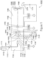
- a low-pressure vessel 1102 has three fluidly connected chambers: a nozzle chamber 1104, an ionization/acceleration chamber 1106, and a processing chamber 1108.
- the three chambers are evacuated by vacuum pumps 1146a, 1146b, and 1146c, respectively.
- a pressurized condensable source gas 1112 (for example argon) stored in a gas storage cylinder 1111 flows through a gas metering valve 1113 and a feed tube 1114 into a stagnation chamber 1116.
- Pressure (typically a few atmospheres) in the stagnation chamber 1116 results in ejection of gas into the substantially lower pressure vacuum through a nozzle 1110, resulting in formation of a supersonic gas jet 1118. Cooling, resulting from the expansion in the jet, causes a portion of the gas jet 1118 to condense into clusters, each consisting of from several to several thousand weakly bound atoms or molecules.
- a gas skimmer aperture 1120 is employed to control flow of gas into the downstream chambers by partially separating gas molecules that have not condensed into a cluster jet from the cluster jet.
- Suitable condensable source gases 1112 include, but are not limited to argon and other condensable noble gases, nitrogen, carbon dioxide, oxygen, and many other gases and/or gas mixtures.
- an ionizer 1122 that is typically an electron impact ionizer that produces electrons by thermal emission from one or more incandescent filaments 1124 (or from other suitable electron sources) and accelerates and directs the electrons, enabling them to collide with gas clusters in the gas jet 1118.
- Electron impacts with gas clusters eject electrons from some portion of the gas clusters, causing those clusters to become positively ionized. Some clusters may have more than one electron ejected and may become multiply ionized.
- a suppressor electrode 1142, and grounded electrode 1144 extract the cluster ions from the ionizer exit aperture 1126, accelerate them to a desired energy (typically with acceleration potentials of from several hundred V to several tens ofkV), and focuses them to form a GCIB 1128.
- the suppressor electrode 1142 is not strictly required and may be omitted.
- the region that the GCIB 1128 traverses between the ionizer exit aperture 126 and the suppressor electrode 1142 is referred to as the extraction region.
- the axis (determined at the nozzle 1110), of the supersonic gas jet 1118 containing gas clusters is substantially the same as the axis 1154 of the GCIB 1128.
- Filament power supply 1136 provides filament voltage V f to heat the ionizer filament 1124.
- Anode power supply 1134 provides anode voltage V A to accelerate thermoelectrons emitted from filament 1124 to cause the thermoelectrons to irradiate the cluster-containing gas jet 1118 to produce cluster ions.
- a suppression power supply 1138 supplies suppression voltage V S (on the order of several hundred to a few thousand volts) to bias suppressor electrode 1142 (when employed). When suppressor electrode 1142 is omitted, as described below, the suppression power supply 1138 may also be omitted.
- Accelerator power supply 1140 supplies acceleration voltage V Acc to bias the ionizer 1122 with respect to suppressor electrode 1142 and grounded electrode 1144 so as to result in a total GCIB acceleration potential equal to V Acc .
- Suppressor electrode 1142 serves to extract ions from the ionizer exit aperture 1126 of ionizer 1122 and to prevent undesired electrons from entering the ionizer 1122 from downstream, and to form a focused GCIB 1128.
- a workpiece 1160 which may (for example) be a medical device, a semiconductor material, an optical element, or other workpiece to be processed by GCIB processing, is held on a workpiece holder 1162, which disposes the workpiece in the path of the GCIB 1128.
- the workpiece holder is attached to but electrically insulated from the processing chamber 1108 by an electrical insulator 1164.
- GCIB 1128 striking the workpiece 1160 and the workpiece holder 1162 flows through an electrical lead 1168 to a dose processor 1170.
- a beam gate 1172 controls transmission of the GCIB 1128 along axis 1154 to the workpiece 1160.
- the beam gate 1172 typically has an open state and a closed state that is controlled by a linkage 1174 that may be (for example) electrical, mechanical, or electromechanical.
- Dose processor 1170 controls the open/closed state of the beam gate 1172 to manage the GCIB dose received by the workpiece 1160 and the workpiece holder 1162. In operation, the dose processor 1170 opens the beam gate 1172 to initiate GCIB irradiation of the workpiece 1160.
- Dose processor 1170 typically integrates GCIB electrical current arriving at the workpiece 1160 and workpiece holder 1162 to calculate an accumulated GCIB irradiation dose. At a predetermined dose, the dose processor 1170 closes the beam gate 1172, terminating processing when the predetermined dose has been achieved.
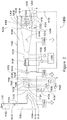
- FIG. 2 shows a schematic illustrating elements of another GCIB processing apparatus 1200 for workpiece processing using a GCIB, wherein scanning of the ion beam and manipulation of the workpiece is employed.
- a workpiece 1160 to be processed by the GCIB processing apparatus 1200 is held on a workpiece holder 1202, disposed in the path of the GCIB 1128.
- the workpiece holder 1202 is designed to manipulate workpiece 1160, as may be required for uniform processing.
- Any workpiece surfaces that are non-planar, for example, spherical or cup-like, rounded, irregular, or other un-flat configuration, may be oriented within a range of angles with respect to the beam incidence to obtain optimal GCIB processing of the workpiece surfaces.
- the workpiece holder 1202 can be fully articulated for orienting all non-planar surfaces to be processed in suitable alignment with the GCIB 1128 to provide processing optimization and uniformity. More specifically, when the workpiece 1160 being processed is non-planar, the workpiece holder 1202 may be rotated in a rotary motion 1210 and articulated in articulation motion 1212 by an articulation/rotation mechanism 1204.
- the articulation/rotation mechanism 1204 may permit 360 degrees of device rotation about longitudinal axis 1206 (which is coaxial with the axis 1154 of the GCIB 1128) and sufficient articulation about an axis 1208 perpendicular to axis 1206 to maintain the workpiece surface to within a desired range of beam incidence.
- a scanning system may be desirable to produce uniform irradiation of a large workpiece.
- two pairs of orthogonally oriented electrostatic scan plates 1130 and 1132 may be utilized to produce a raster or other scanning pattern over an extended processing area.
- a scan generator 1156 provides X-axis scanning signal voltages to the pair of scan plates 1132 through lead pair 1159 and Y-axis scanning signal voltages to the pair of scan plates 1130 through lead pair 1158.
- the scanning signal voltages are commonly triangular waves of different frequencies that cause the GCIB 1128 to be converted into a scanned GCIB 1148, which scans the entire surface of the workpiece 1160.
- a scanned beam-defining aperture 1214 defines a scanned area.
- the scanned beam-defining aperture 1214 is electrically conductive and is electrically connected to the low-pressure vessel 1102 wall and supported by support member 1220.
- the workpiece holder 1202 is electrically connected via a flexible electrical lead 1222 to a faraday cup 1216 that surrounds the workpiece 1160 and the workpiece holder 1202 and collects all the current passing through the defining aperture 1214.
- the workpiece holder 1202 is electrically isolated from the articulation/rotation mechanism 1204 and the faraday cup 1216 is electrically isolated from and mounted to the low-pressure vessel 1102 by insulators 1218. Accordingly, all current from the scanned GCIB 1148, which passes through the scanned beam-defining aperture 1214 is collected in the faraday cup 1216 and flows through electrical lead 1224 to the dose processor 1170. In operation, the dose processor 1170 opens the beam gate 1172 to initiate GCIB irradiation of the workpiece 1160. The dose processor 1170 typically integrates GCIB electrical current arriving at the workpiece 1160 and workpiece holder 1202 and faraday cup 1216 to calculate an accumulated GCIB irradiation dose per unit area.
- the dose processor 1170 closes the beam gate 1172, terminating processing when the predetermined dose has been achieved.
- the workpiece 1160 may be manipulated by the articulation/rotation mechanism 1204 to ensure processing of all desired surfaces.
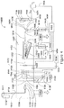
- FIG. 3 is a schematic of a Neutral Beam processing apparatus 1300 of an exemplary type that may be employed for Neutral Beam processing according to embodiments of the invention. It uses electrostatic deflection plates to separate the charged and uncharged portions of a GCIB, A beamline chamber 1107 encloses the ionizer and accelerator regions and the workpiece processing regions. The beamline chamber 1107 has high conductance and so the pressure is substantially uniform throughout. A vacuum pump 1146b evacuates the beamline chamber 1107. Gas flows into the beamline chamber 1107 in the form of clustered and unclustered gas transported by the gas jet 1118 and in the form of additional unclustered gas that leaks through the gas skimmer aperture 1120.
- a pressure sensor 1330 transmits pressure data from the beamline chamber 1107 through an electrical cable 1332 to a pressure sensor controller 1334, which measures and displays pressure in the beamline chamber 1107.
- the pressure in the beamline chamber 1107 depends on the balance of gas flow into the headline chamber 1107 and the pumping speed of the vacuum pump 1146b.
- the pressure in the beamline chamber 1107 equilibrates at a pressure, PB, determined by design and by nozzle flow.
- the beam flight path from grounded electrode 1144 to workpiece holder 162 is for example, 100 cm.
- PB may be approximately 6 x 10 -5 torr (8 x 10 -3 pascal).
- the product of pressure and beam path length is approximately 6 x 10 -3 torr-cm (0,8 pascal-cm) and the gas target thickness for the beam is approximately 1,94 x 10 14 gas molecules per cm 2 , which is observed to be effective for dissociating the gas-cluster ions in the GCIB 1128.
- V Acc may be for example 30kV and the GCIB 1128 is accelerated by that potential.
- a pair of deflection plates (1302 and 1304) is disposed about the axis 1154 of the GCIB 1128.
- a deflector power supply 1306 provides a positive deflection voltage V D to deflection plate 1302 via electrical lead 1308.
- Deflection plate 1304 is connected to electrical ground by electrical lead 1312 and through current sensor/display 1310.
- Deflector power supply 1306 is manually controllable.
- V D may be adjusted from zero to a voltage sufficient to completely deflect the ionized portion 1316 of the GCIB 1128 onto the deflection plate 1304 (for example a few thousand volts).
- I D flows through electrical lead 1312 and current sensor/display 1310 for indication.
- V D is zero, the GCIB 1128 is undeflected and travels to the workpiece 1160 and the workpiece holder 1162.
- the GCIB beam current I B is collected on the workpiece 1160 and the workpiece holder 1162 and flows through electrical lead 1168 and current sensor/display 1320 to electrical ground. I B is indicated on the current sensor/display 1320.
- a beam gate 1172 is controlled through a linkage 1338 by beam gate controller 1336. Beam gate controller 1336 may be manual or may be electrically or mechanically timed by a preset value to open the beam gate 1172 for a predetermined interval. In use, V D is set to zero and the beam current, I B , striking the workpiece holder is measured. Based on previous experience for a given GCIB process recipe, an initial irradiation time for a given process is determined based on the measured current, I B .
- V D is increased until all measured beam current is transferred from I B to I D and I D no longer increases with increasing V D .
- a Neutral Beam 1314 comprising energetic dissociated components of the initial GCIB 1128 irradiates the workpiece holder 1162.
- the beam gate 1172 is then closed and the workpiece 1160 placed onto the workpiece holder 1162 by conventional workpiece loading means (not shown).
- the beam gate 1172 is opened for the predetermined initial radiation time.
- the workpiece may be examined and the processing time adjusted as necessary to calibrate the duration of Neutral Beam processing based on the measured GCIB beam current I B . Following such a calibration process, additional workpieces may be processed using the calibrated exposure duration.
- the Neutral Beam 1314 contains a repeatable fraction of the initial energy of the accelerated GCIB 1128.
- the remaining ionized portion 1316 of the original GCIB 1128 has been removed from the Neutral Beam 1314 and is collected by the grounded deflection plate 1304.
- the ionized portion 1316 that is removed from the Neutral Beam 1314 may include monomer ions and gas-cluster ions including intermediate size gas-cluster ions. Because of the monomer evaporation mechanisms due to cluster heating during the ionization process, intra-beam collisions, background gas collisions, and other causes (all of which result in erosion of clusters) the Neutral Beam substantially consists of neutral monomers, while the separated charged particles are predominately cluster ions. The inventors have confirmed this by suitable measurements that include re-ionizing the Neutral Beam and measuring the charge to mass ratio of the resulting ions. As will be shown below, certain superior process results are obtained by processing workpieces using this Neutral Beam.
- FIG. 4 is a schematic of a Neutral Beam processing apparatus 1400 as may, for example, be used in generating Neutral Beams as may be employed in embodiments of the invention. It uses a thermal sensor for Neutral Beam measurement.
- a thermal sensor 1402 attaches via low thermal conductivity attachment 1404 to a rotating support arm 1410 attached to a pivot 1412.
- Actuator 1408 moves thermal sensor 1402 via a reversible rotary motion 1416 between positions that intercept the Neutral Beam 1314 or GCIB 1128 and a parked position indicated by 1414 where the thermal sensor 1402 does not intercept any beam.
- thermal sensor 1402 When thermal sensor 1402 is in the parked position (indicated by 1414) the GCIB 1128 or Neutral Beam 1314 continues along path 1406 for irradiation of the workpiece 1160 and/or workpiece holder 1162.
- a thermal sensor controller 1420 controls positioning of the thermal sensor 1402 and performs processing of the signal generated by thermal sensor 1402.
- Thermal sensor 1402 communicates with the thermal sensor controller 1420 through an electrical cable 1418.
- Thermal sensor controller 1420 communicates with a dosimetry controller 1432 through an electrical cable 1428.
- a beam current measurement device 1424 measures beam current I B flowing in electrical lead 1168 when the GCIB 1128 strikes the workpiece 1160 and/or the workpiece holder 1162.
- Beam current measurement device 1424 communicates a beam current measurement signal to dosimetry controller 1432 via electrical cable 1426.
- Dosimetry controller 1432 controls setting of open and closed states for beam gate 1172 by control signals transmitted via linkage 1434.
- Dosimetry controller 1432 controls deflector power supply 1440 via electrical cable 1442 and can control the deflection voltage V D between voltages of zero and a positive voltage adequate to completely deflect the ionized portion 1316 of the GCIB 1128 to the deflection plate 1304.
- the resulting current I D is measured by current sensor 1422 and communicated to the dosimetry controller 1432 via electrical cable 1430.
- dosimetry controller 1432 sets the thermal sensor 1402 to the parked position 1414, opens beam gate 1172, and sets V D to zero so that the full GCIB 1128 strikes the workpiece holder 1162 and/or workpiece 1160.
- the dosimetry controller 1432 records the beam current I B transmitted from beam current measurement device 1424.
- the dosimetry controller 1432 then moves the thermal sensor 1402 from the parked position 1414 to intercept the GCIB 1128 by commands relayed through thermal sensor controller 1420.
- Thermal sensor controller 1420 measures the beam energy flux of GCIB 1128 by calculation based on the heat capacity of the sensor and measured rate of temperature rise of the thermal sensor 1402 as its temperature rises through a predetermined measurement temperature (for example 70 degrees C) and communicates the calculated beam energy flux to the dosimetry controller 1432 which then calculates a calibration of the beam energy flux as measured by the thermal sensor 1402 and the corresponding beam current measured by the beam current measurement device 1424.
- the dosimetry controller 1432 parks the thermal sensor 1402 at parked position 1414, allowing it to cool and commands application of positive V D to deflection plate 1302 until the entire current I D due to the ionized portion of the GCIB 1128 is transferred to the deflection plate 1304.
- the current sensor 1422 measures the corresponding I D and communicates it to the dosimetry controller 1432.
- the dosimetry controller also moves the thermal sensor 1402 from parked position 1414 to intercept the Neutral Beam 1314 by commands relayed through thermal sensor controller 420.
- Thermal sensor controller 420 measures the beam energy flux of the Neutral Beam 1314 using the previously determined calibration factor and the rate of temperature rise of the thermal sensor 1402 as its temperature rises through the predetermined measurement temperature and communicates the Neutral Beam energy flux to the dosimetry controller 1432.
- the dosimetry controller 1432 calculates a neutral beam fraction, which is the ratio of the thermal measurement of the Neutral Beam 1314 energy flux to the thermal measurement of the full GCIB 1128 energy flux at sensor 1402.
- the dosimetry controller 1432 Before beginning processing, the dosimetry controller 1432 also measures the current, I D , and determines a current ratio between the initial values of I B and I D . During processing, the instantaneous I D measurement multiplied by the initial I B /I D ratio may be used as a proxy for continuous measurement of the I B and employed for dosimetry during control of processing by the dosimetry controller 1432. Thus the dosimetry controller 1432 can compensate any beam fluctuation during workpiece processing, just as if an actual beam current measurement for the full GCIB 1128 were available. The dosimetry controller uses the neutral beam fraction to compute a desired processing time for a particular beam process. During the process, the processing time can be adjusted based on the calibrated measurement of I D for correction of any beam fluctuation during the process.
- FIG 5 is a schematic of a somewhat simplified Neutral Beam processing apparatus 1500 as may, for example, be used in generating deflected, aligned, or scanned Neutral Beams as may be employed in embodiments of the invention. It is identical to the Neutral Beam processing apparatus 1400 shown previously, with a simplification to the beam extraction and acceleration scheme employed at the exit of the ionizer. The simplification of Neutral Beam processing apparatus 1500 is omission of the suppression power supply 1138 and the suppressor electrode 1142 (both shown in Figure 4 , Neutral Beam processing apparatus 1400).
- ground electrode 1144 serves to extract ions from the ionizer 1122 and to accelerate the gas-cluster ions and to form the GCIB 1128.
- Accelerator power supply 1140 supplies acceleration voltage V Acc to bias the ionizer 1122 with respect to grounded electrode 1144 so as to result in a total GCIB acceleration potential equal to V Acc .
- the Neutral Beam processing system 1500 is somewhat simplified in comparison to the Neutral Beam processing system 1400, at the expense of somewhat heavier current loading of the accelerator power supply 1140 that provides V ACC .
- FIG. 6 is a schematic 600 showing a concept underlying embodiments of the invention that permit mechanical steering of the Neutral Beam in a Neutral Beam apparatus similar to the simplified Neutral Beam processing apparatus 1500 shown previously in Figure 5 .
- a gas jet 1118 enters ionizer 1122 where it is ionized to form a gas-cluster ion-beam travelling along a path 606 (or 606') which are extracted from the ionizer exit aperture 1126 by the electric field between ionizer exit aperture 1126 and ground electrode 1144'.
- ionizer 1122 and ionizer exit aperture 1126 are biased as shown in previous Figure 5 .
- Ground electrode 1144' is grounded as was ground electrode 1144 in previous Figure 5 .
- ground electrode 1144' is similar to previously shown ground electrode 1144, except it is tilted slightly with respect to the path of gas-cluster ions 606 by a tilt angle 602 that is less than 90 degrees.
- the distortion of the electric field between ionizer exit aperture 1126 and the ground electrode 1144' causes deflection of the gas-cluster ions that would otherwise follow path 606 onto path 606' with a resulting beam deflection angle 604 that is greater than zero degrees.
- the beam deflection angle 604 is varied, with 604 increasing as 602 decreases.
- the beam deflection angle 604 of the GCIB increases and the GCIB becomes GCIB 1128' deflected from original GCIB 1128.
- the tilt angle 602 is preferably less than 90 degrees and greater than 70 degrees with respect to the initial path.
- dissociation of the deflected accelerated GCIB 1128' proceeds.
- the pair of deflection plates (1302 and 1304) are biased as shown previously in Figure 5 .
- the ionized portion 1316 of the GCIB 1128' is deflected onto the deflection plate 1304 and a deflected neutral beam 1314' that is free of charged particles is transmitted.
- the path of the deflected neutral beam 1314' is deflected from the path of neutral beam 1314 that occurs when the tilt angle 602 of the ground electrode 1144' is 90 degrees.
- Figures 7A and 7B are two orthogonal views of a tiltable ground electrode assembly 700 that is compatible with the simplified Neutral Beam processing apparatus 1500 shown in Figure 5 .
- Figure 7A is a sectional view looking along the direction of the path of gas-cluster ions 606 and looking away from the ionizer and towards the downstream workpiece.
- a tiltable ground electrode 702 is mounted in a gimbal arrangement in a tiltable ground electrode support 704.
- Tiltable ground electrode 702 can be tilted about a first tilt axis 710, which may be a horizontal axis and also about as second tilt axis 716, which may be a vertical axis.
- Axes 710 and 716 are preferably but not necessarily orthogonal to one another.
- a first tilt actuator 708 provides a first rotary motion 712 to tilt the gimbal ring 706 and the tiltable ground electrode about the first tilt axis 710
- a second tilt actuator 714 provides a second rotary motion 718 to tilt the tiltable ground electrode about the second tilt axis 716 relative to the gimbal ring 706.
- the first tilt actuator 708 and the second tilt actuator 714 may be actuated independently or simultaneously to tilt about either or both of the tilt axes 710 and 716.
- Tilt actuators 708 and 714 may either or both be either manually actuated or actuated by a controllable system such as a stepper motor under electronic control.
- the compound tilt angle resulting from the compound rotary motions 712 and 718 result in a particular tilt of the tiltable ground electrode 702.
- the rotary motions 712 and 718 may be periodic and produce a continuously varying compound tilting of the tiltable ground electrode 702 for beam scanning.
- Figure 7B is a sectional view orthogonal to the view of 7A and is shown in section.
- the path of the gas-cluster ions 606 (having been extracted from an upstream ionizer not shown in this view) enters the ground electrode aperture 720 and departs as an accelerated GCIB. 1128.
- the accelerated GCIB may also depart as deflected GCIBs 1128' or 1128" (for examples).
- the accelerated GCIB may depart in the downstream direction of GCIB. 1128, 1128', or 1128" but also deflected into or out of the plane of the paper in a compound beam deflection angle.
- the beam is scanned.
- small angular adjustments to tiltable ground electrode 702 can be employed to bring the exiting beam into alignment with desired GCIB 1128 pathway.
- FIG 8 is a schematic of a Neutral Beam processing apparatus 1550 as may, for example, be used in generating Neutral Beams as may be employed in embodiments of the invention.
- a tiltable ground electrode assembly 700 contains a tiltable ground electrode 702.
- Compound tilt motions 1556 permit steering the downstream GCIB 1128 along a desired pathway 1510 or other pathways (1508 for example) to align the downstream beam path as desired.
- a downstream neutral beam sensor for example a thermal sensor 1402 having a small sensitive area 1512 can be used to align the downstream Neutral Beam 1314 toward a workpiece 1160 or other selected spot.
- a method and apparatus for controlling the direction of a Neutral Beam derived from a GCIB includes an acceleration electrode having an aperture encircling a beam path for a GCIB portion of the beam and a mounting apparatus for the electrode enabling tilting of the electrode in polar directions relative to the beam path.
- the electrode is mounted for tilting along two axes that are generally orthogonal to the beam path and the axes may be orthogonal to each other. Tilting of the electrode may be precisely electrically controlled to provide beam scanning and beam alignment and otherwise provide deflection to the GCIB portion of the beam.
- a thermal sensor may be included in a Neutral Beam portion for measuring beam power. The area of the sensor exposable to the Neutral Beam may be limited as a means of beam alignment.
Landscapes
- Physics & Mathematics (AREA)
- Spectroscopy & Molecular Physics (AREA)
- Engineering & Computer Science (AREA)
- Plasma & Fusion (AREA)
- Chemical & Material Sciences (AREA)
- Analytical Chemistry (AREA)
- Electron Sources, Ion Sources (AREA)
- Particle Accelerators (AREA)
- Radiation-Therapy Devices (AREA)
Claims (11)
- Appareil pour le contrôle d'une direction et d'un alignement d'un faisceau neutre issu d'un faisceau d'ions d'amas gazeux, l'appareil comprenant :a. un appareil (1100) pour former un faisceau d'ions d'amas gazeux (1128) ayant un axe initial déterminé au niveau d'une buse à jet de gaz (1110) dans une source d'ions (1126) qui a une ouverture de sortie encerclant l'axe initial et une électrode d'accélération (1144', 702) espacée de l'ouverture de sortie, ladite électrode d'accélération ayant une ouverture (720) encerclant l'axe initial ;dans lequel l'électrode d'accélération et son ouverture (720) sont configurées pour être inclinées à un premier angle d'inclinaison le long d'un premier axe d'inclinaison, par rapport à l'axe initial du faisceau d'ions d'amas gazeux (1128) ;dans lequel en outre l'électrode d'accélération est configurée pour être électriquement polarisée par rapport à la source d'ions (1126) pour accélérer et cibler le faisceau d'ions d'amas gazeux (1128) dans une région entre l'ouverture de sortie (702) de la source d'ions et l'ouverture de l'électrode d'accélération ;dans lequel encore en outre l'électrode d'accélération et son ouverture sont configurées pour être inclinées à un second angle d'inclinaison le long d'un second axe d'inclinaison par rapport au trajet initial du faisceau d'ions d'amas gazeux (1128) et la déviation résultante est une déviation composite, les premier et second axes d'inclinaison étant distincts, etdans lequel encore en outre le premier angle d'inclinaison et le second angle d'inclinaison permettent un alignement et conduisent à une déviation du faisceau d'ions d'amas gazeux (1128) à l'écart de l'axe initial le long d'un premier trajet dévié ;b. un espace de glissement pour le faisceau d'ions d'amas gazeux (1128) dévié, une dissociation d'ions d'amas gazeux ayant lieu dans le faisceau d'ions d'amas gazeux (1128) accéléré et ciblé, produisant des particules neutres accélérées et ciblées ; etc. des moyens (1302, 1304) pour la séparation d'ions à partir de particules neutres pour retirer des ions à partir du trajet de faisceau dévié, de sorte que les particules neutres accélérées suivent le trajet de faisceau dévié (1154) en tant que faisceau neutre.
- Appareil (1100) de la revendication 1, dans lequel le premier angle d'inclinaison est inférieur à 90 degrés et, facultativement, dans lequel le premier angle d'inclinaison est supérieur à 70 degrés.
- Appareil (1100) de la revendication 1, dans lequel le premier angle d'inclinaison est variable de manière contrôlée et la déviation résultante du faisceau d'ions d'amas gazeux (1128) est variable.
- Appareil (1100) de la revendication 1, dans lequel le second angle d'inclinaison est(a) inférieur à 90 degrés et supérieur à 70 degrés ; ou(b) variable de manière contrôlée et la déviation résultante du faisceau d'ions d'amas gazeux (1128) est variable.
- Appareil (1100) de la revendication 1, dans lequel le premier angle d'inclinaison et le second angle d'inclinaison sont chacun variables de manière contrôlée et, facultativement, comprenant en outre des moyens pour le contrôle des premier et second angles d'inclinaison pour produire un faisceau neutre à balayage tramé.
- Procédé pour la production d'une déviation et d'un alignement d'un faisceau neutre issu d'un faisceau d'ions d'amas gazeux (1128) ayant un axe initial déterminé au niveau d'une buse à jet de gaz (1126) dans une source d'ions (1126) qui a une ouverture de sortie encerclant l'axe initial, le procédé comprenant les étapes suivantes consistant à :a. encercler l'axe initial avec une ouverture (720) dans une électrode d'accélération espacée de l'ouverture de sortie ;b. polariser électriquement l'électrode d'accélération par rapport à la source d'ions (1126) pour fournir un faisceau d'ions d'amas gazeux accéléré et ciblé dans une région d'accélération entre l'ouverture de sortie de la source d'ions et l'ouverture (720) de l'électrode d'accélération ;c. incliner en premier lieu l'électrode d'accélération et son ouverture (720) à un premier angle d'inclinaison, le long d'un premier axe d'inclinaison, par rapport à l'axe initial du faisceau d'ions d'amas gazeux, le faisceau d'ions d'amas gazeux étant dévié à l'écart de l'axe initial le long d'un premier trajet dévié ;d. incliner en second lieu l'électrode d'accélération et son ouverture (720) à un second angle d'inclinaison, le long d'un second axe d'inclinaison distinct du premier axe d'inclinaison, par rapport à l'axe initial du faisceau d'ions d'amas gazeux, produisant une déviation résultante qui est une déviation composite ;e. fournir un espace de glissement pour le faisceau d'ions d'amas gazeux dévié, une dissociation d'ions d'amas gazeux ayant lieu dans le faisceau d'ions d'amas gazeux accéléré et ciblé, produisant des particules neutres accélérées et ciblées ; etf. séparer des ions à partir de particules neutres pour retirer des ions à partir du trajet de faisceau dévié (1154), permettant aux particules neutres accélérées et ciblées de suivre le trajet de faisceau dévié (1154) en tant que faisceau neutre.
- Procédé de la revendication 6, dans lequel le premier angle d'inclinaison est(a) inférieur à 90 degrés et supérieur à 70 degrés ; ou(b) variable de manière contrôlée et l'on fait varier la déviation résultante du faisceau d'ions d'amas gazeux.
- Procédé de la revendication 6, dans lequel le second angle d'inclinaison est(a) inférieur à 90 degrés et supérieur à 70 degrés par rapport à l'axe initial ; ou(b) variable de manière contrôlée et l'on fait varier la déviation résultante du faisceau d'ions d'amas gazeux.
- Procédé de la revendication 6, dans lequel on fait varier le premier angle d'inclinaison et le second angle d'inclinaison chacun de manière contrôlée et les premier et second axes d'inclinaison sont distincts.
- Procédé de la revendication 6, dans lequel les premier et second axes d'inclinaison sont perpendiculaires l'un à l'autre et à l'axe initial.
- Procédé de la revendication 10, comprenant en outre l'étape consistant à contrôler de manière variable les premier ou second angles d'inclinaison pour produire(a) un faisceau neutre balayé ; ou(b) un faisceau neutre balayé, balayé en deux dimensions.
Applications Claiming Priority (2)
| Application Number | Priority Date | Filing Date | Title |
|---|---|---|---|
| US201361760238P | 2013-02-04 | 2013-02-04 | |
| PCT/US2014/014720 WO2014121285A2 (fr) | 2013-02-04 | 2014-02-04 | Méthode et appareil pour diriger un faisceau neutre |
Publications (3)
| Publication Number | Publication Date |
|---|---|
| EP2952070A2 EP2952070A2 (fr) | 2015-12-09 |
| EP2952070A4 EP2952070A4 (fr) | 2016-10-12 |
| EP2952070B1 true EP2952070B1 (fr) | 2018-05-30 |
Family
ID=51263133
Family Applications (1)
| Application Number | Title | Priority Date | Filing Date |
|---|---|---|---|
| EP14745537.2A Not-in-force EP2952070B1 (fr) | 2013-02-04 | 2014-02-04 | Méthode et appareil pour diriger un faisceau neutre |
Country Status (5)
| Country | Link |
|---|---|
| US (2) | US20150366044A1 (fr) |
| EP (1) | EP2952070B1 (fr) |
| JP (1) | JP6408490B2 (fr) |
| RU (1) | RU2653581C2 (fr) |
| WO (1) | WO2014121285A2 (fr) |
Families Citing this family (8)
| Publication number | Priority date | Publication date | Assignee | Title |
|---|---|---|---|---|
| US10825685B2 (en) | 2010-08-23 | 2020-11-03 | Exogenesis Corporation | Method for neutral beam processing based on gas cluster ion beam technology and articles produced thereby |
| CN103180030B (zh) | 2010-08-23 | 2017-04-12 | 艾克索乔纳斯公司 | 基于气体团簇离子束技术的中性射束处理方法和设备 |
| US10181402B2 (en) * | 2010-08-23 | 2019-01-15 | Exogenesis Corporation | Method and apparatus for neutral beam processing based on gas cluster ion beam technology and articles produced thereby |
| US9540725B2 (en) * | 2014-05-14 | 2017-01-10 | Tel Epion Inc. | Method and apparatus for beam deflection in a gas cluster ion beam system |
| US9685298B1 (en) * | 2016-02-01 | 2017-06-20 | Varian Semiconductor Equipment Associates, Inc. | Apparatus and method for contamination control in ion beam apparatus |
| US11643724B2 (en) * | 2019-07-18 | 2023-05-09 | Asm Ip Holding B.V. | Method of forming structures using a neutral beam |
| DE112022000720T5 (de) * | 2021-01-22 | 2023-11-16 | Exogenesis Corporation | Mit einem beschleunigten neutralen atomstrahl (bnas) modifiziertes polypropylen zur reduzierung der bakterienbesiedlung ohne antibiotika |
| US20230402284A1 (en) * | 2022-06-10 | 2023-12-14 | Applied Materials, Inc. | Patterning layer modification using directional radical ribbon beam |
Family Cites Families (21)
| Publication number | Priority date | Publication date | Assignee | Title |
|---|---|---|---|---|
| NL278803A (fr) * | 1961-05-25 | |||
| US3588230A (en) * | 1969-01-13 | 1971-06-28 | Us Navy | Adjustable lens mount |
| JPS5719946A (en) * | 1980-07-11 | 1982-02-02 | Hitachi Ltd | Ion take-out section for ion injector |
| DE3235068A1 (de) * | 1982-09-22 | 1984-03-22 | Siemens AG, 1000 Berlin und 8000 München | Varioformstrahl-ablenkobjektiv fuer neutralteilchen und verfahren zu seinem betrieb |
| US4775789A (en) * | 1986-03-19 | 1988-10-04 | Albridge Jr Royal G | Method and apparatus for producing neutral atomic and molecular beams |
| JPS6412453A (en) * | 1987-07-06 | 1989-01-17 | Fuji Electric Co Ltd | Ion implanter |
| US4935623A (en) * | 1989-06-08 | 1990-06-19 | Hughes Aircraft Company | Production of energetic atom beams |
| JPH08184698A (ja) * | 1994-12-28 | 1996-07-16 | Ebara Corp | 高速原子線装置 |
| US5693939A (en) * | 1996-07-03 | 1997-12-02 | Purser; Kenneth H. | MeV neutral beam ion implanter |
| JPH11185647A (ja) * | 1997-12-22 | 1999-07-09 | Nec Corp | イオン源装置 |
| US6441382B1 (en) * | 1999-05-21 | 2002-08-27 | Axcelis Technologies, Inc. | Deceleration electrode configuration for ultra-low energy ion implanter |
| DE60041149D1 (de) * | 1999-12-06 | 2009-01-29 | Tel Epion Inc | Gerät zum glätten von substraten mittels gas-cluster-ionenstrahlung |
| JP3727050B2 (ja) * | 2001-01-19 | 2005-12-14 | 住友イートンノバ株式会社 | イオン注入装置及びそのイオンソース系の調節方法。 |
| JP4449064B2 (ja) * | 2003-01-27 | 2010-04-14 | ティーイーエル エピオン インク. | ガスクラスタ・イオン・ビームを測定しかつ制御する方法とそのための装置 |
| JP5100963B2 (ja) * | 2004-11-30 | 2012-12-19 | 株式会社Sen | ビーム照射装置 |
| US7825389B2 (en) * | 2007-12-04 | 2010-11-02 | Tel Epion Inc. | Method and apparatus for controlling a gas cluster ion beam formed from a gas mixture |
| RU2362277C1 (ru) * | 2008-02-14 | 2009-07-20 | Федеральное государственное унитарное предприятие "Всероссийский научно-исследовательский институт автоматики им. Н.Л. Духова" (ФГУП "ВНИИА") | Способ генерации нейтронных импульсов |
| US7994488B2 (en) * | 2008-04-24 | 2011-08-09 | Axcelis Technologies, Inc. | Low contamination, low energy beamline architecture for high current ion implantation |
| EP2567012B1 (fr) * | 2010-05-05 | 2015-12-16 | Exogenesis Corporation | Procédés d'amélioration des caractéristiques de bioactivité d'une surface et objets ayant des surfaces améliorées par ce procédé |
| US8481960B2 (en) * | 2010-06-28 | 2013-07-09 | Varian Semiconductor Equipment Associates, Inc. | Deceleration lens |
| CN103180030B (zh) * | 2010-08-23 | 2017-04-12 | 艾克索乔纳斯公司 | 基于气体团簇离子束技术的中性射束处理方法和设备 |
-
2014
- 2014-02-04 EP EP14745537.2A patent/EP2952070B1/fr not_active Not-in-force
- 2014-02-04 US US14/763,989 patent/US20150366044A1/en not_active Abandoned
- 2014-02-04 RU RU2015137676A patent/RU2653581C2/ru active
- 2014-02-04 WO PCT/US2014/014720 patent/WO2014121285A2/fr not_active Ceased
- 2014-02-04 JP JP2015556236A patent/JP6408490B2/ja active Active
-
2019
- 2019-09-19 US US16/576,458 patent/US20200022247A1/en not_active Abandoned
Non-Patent Citations (1)
| Title |
|---|
| None * |
Also Published As
| Publication number | Publication date |
|---|---|
| JP2016507133A (ja) | 2016-03-07 |
| RU2015137676A (ru) | 2017-03-10 |
| JP6408490B2 (ja) | 2018-10-17 |
| WO2014121285A2 (fr) | 2014-08-07 |
| WO2014121285A3 (fr) | 2015-02-19 |
| US20200022247A1 (en) | 2020-01-16 |
| EP2952070A2 (fr) | 2015-12-09 |
| EP2952070A4 (fr) | 2016-10-12 |
| HK1218828A1 (en) | 2017-03-10 |
| RU2653581C2 (ru) | 2018-05-15 |
| US20150366044A1 (en) | 2015-12-17 |
Similar Documents
| Publication | Publication Date | Title |
|---|---|---|
| US20200022247A1 (en) | Method and apparatus for directing a neutral beam | |
| KR101603196B1 (ko) | 조정가능한 통공을 구비한 이온 소스 | |
| EP2608872B1 (fr) | Procédé et appareil de traitement par faisceau neutre basés sur la technologie des faisceaux ioniques d'agrégats gazeux | |
| EP2748835B1 (fr) | Procédés et appareils pour employer un faisceau neutre accéléré pour une analyse de surface améliorée | |
| JP4449064B2 (ja) | ガスクラスタ・イオン・ビームを測定しかつ制御する方法とそのための装置 | |
| JP2008518407A (ja) | ガスクラスターイオンビーム形成のためのイオナイザおよび方法 | |
| JP2016524277A (ja) | イオン注入システムにおける抽出電極アッセンブリの電圧変調 | |
| US20160004152A1 (en) | Defect reduction in a substrate treatment method | |
| CN1922707A (zh) | 调制离子束电流 | |
| US9117628B2 (en) | Diagnostic method and apparatus for characterization of a neutral beam and for process control therewith | |
| HK1218828B (en) | Method and apparatus for directing a neutral beam | |
| US20150351892A1 (en) | Treatment method for inhibiting platelet attachment and articles treated thereby | |
| US20240018003A1 (en) | Using anab technology to remove production processing residuals from graphene | |
| US10971324B2 (en) | Treatment method for inhibiting platelet attachment and articles treated thereby | |
| HK1198727B (en) | Diagnostic method and apparatus for characterization of a neutral beam and for process control therewith |
Legal Events
| Date | Code | Title | Description |
|---|---|---|---|
| PUAI | Public reference made under article 153(3) epc to a published international application that has entered the european phase |
Free format text: ORIGINAL CODE: 0009012 |
|
| 17P | Request for examination filed |
Effective date: 20150904 |
|
| AK | Designated contracting states |
Kind code of ref document: A2 Designated state(s): AL AT BE BG CH CY CZ DE DK EE ES FI FR GB GR HR HU IE IS IT LI LT LU LV MC MK MT NL NO PL PT RO RS SE SI SK SM TR |
|
| AX | Request for extension of the european patent |
Extension state: BA ME |
|
| DAX | Request for extension of the european patent (deleted) | ||
| REG | Reference to a national code |
Ref country code: DE Ref legal event code: R079 Ref document number: 602014026246 Country of ref document: DE Free format text: PREVIOUS MAIN CLASS: H05H0003020000 Ipc: H01J0037147000 |
|
| A4 | Supplementary search report drawn up and despatched |
Effective date: 20160912 |
|
| RIC1 | Information provided on ipc code assigned before grant |
Ipc: H01J 37/317 20060101ALI20160906BHEP Ipc: H05H 3/02 20060101ALI20160906BHEP Ipc: H01J 37/147 20060101AFI20160906BHEP |
|
| GRAP | Despatch of communication of intention to grant a patent |
Free format text: ORIGINAL CODE: EPIDOSNIGR1 |
|
| STAA | Information on the status of an ep patent application or granted ep patent |
Free format text: STATUS: GRANT OF PATENT IS INTENDED |
|
| INTG | Intention to grant announced |
Effective date: 20171208 |
|
| GRAS | Grant fee paid |
Free format text: ORIGINAL CODE: EPIDOSNIGR3 |
|
| GRAA | (expected) grant |
Free format text: ORIGINAL CODE: 0009210 |
|
| STAA | Information on the status of an ep patent application or granted ep patent |
Free format text: STATUS: THE PATENT HAS BEEN GRANTED |
|
| AK | Designated contracting states |
Kind code of ref document: B1 Designated state(s): AL AT BE BG CH CY CZ DE DK EE ES FI FR GB GR HR HU IE IS IT LI LT LU LV MC MK MT NL NO PL PT RO RS SE SI SK SM TR |
|
| REG | Reference to a national code |
Ref country code: GB Ref legal event code: FG4D |
|
| REG | Reference to a national code |
Ref country code: CH Ref legal event code: EP |
|
| REG | Reference to a national code |
Ref country code: AT Ref legal event code: REF Ref document number: 1004465 Country of ref document: AT Kind code of ref document: T Effective date: 20180615 |
|
| REG | Reference to a national code |
Ref country code: IE Ref legal event code: FG4D |
|
| REG | Reference to a national code |
Ref country code: DE Ref legal event code: R096 Ref document number: 602014026246 Country of ref document: DE |
|
| REG | Reference to a national code |
Ref country code: NL Ref legal event code: MP Effective date: 20180530 |
|
| REG | Reference to a national code |
Ref country code: LT Ref legal event code: MG4D |
|
| PG25 | Lapsed in a contracting state [announced via postgrant information from national office to epo] |
Ref country code: SE Free format text: LAPSE BECAUSE OF FAILURE TO SUBMIT A TRANSLATION OF THE DESCRIPTION OR TO PAY THE FEE WITHIN THE PRESCRIBED TIME-LIMIT Effective date: 20180530 Ref country code: CY Free format text: LAPSE BECAUSE OF FAILURE TO SUBMIT A TRANSLATION OF THE DESCRIPTION OR TO PAY THE FEE WITHIN THE PRESCRIBED TIME-LIMIT Effective date: 20180530 Ref country code: FI Free format text: LAPSE BECAUSE OF FAILURE TO SUBMIT A TRANSLATION OF THE DESCRIPTION OR TO PAY THE FEE WITHIN THE PRESCRIBED TIME-LIMIT Effective date: 20180530 Ref country code: BG Free format text: LAPSE BECAUSE OF FAILURE TO SUBMIT A TRANSLATION OF THE DESCRIPTION OR TO PAY THE FEE WITHIN THE PRESCRIBED TIME-LIMIT Effective date: 20180830 Ref country code: NO Free format text: LAPSE BECAUSE OF FAILURE TO SUBMIT A TRANSLATION OF THE DESCRIPTION OR TO PAY THE FEE WITHIN THE PRESCRIBED TIME-LIMIT Effective date: 20180830 Ref country code: ES Free format text: LAPSE BECAUSE OF FAILURE TO SUBMIT A TRANSLATION OF THE DESCRIPTION OR TO PAY THE FEE WITHIN THE PRESCRIBED TIME-LIMIT Effective date: 20180530 Ref country code: LT Free format text: LAPSE BECAUSE OF FAILURE TO SUBMIT A TRANSLATION OF THE DESCRIPTION OR TO PAY THE FEE WITHIN THE PRESCRIBED TIME-LIMIT Effective date: 20180530 |
|
| PG25 | Lapsed in a contracting state [announced via postgrant information from national office to epo] |
Ref country code: GR Free format text: LAPSE BECAUSE OF FAILURE TO SUBMIT A TRANSLATION OF THE DESCRIPTION OR TO PAY THE FEE WITHIN THE PRESCRIBED TIME-LIMIT Effective date: 20180831 Ref country code: HR Free format text: LAPSE BECAUSE OF FAILURE TO SUBMIT A TRANSLATION OF THE DESCRIPTION OR TO PAY THE FEE WITHIN THE PRESCRIBED TIME-LIMIT Effective date: 20180530 Ref country code: LV Free format text: LAPSE BECAUSE OF FAILURE TO SUBMIT A TRANSLATION OF THE DESCRIPTION OR TO PAY THE FEE WITHIN THE PRESCRIBED TIME-LIMIT Effective date: 20180530 Ref country code: RS Free format text: LAPSE BECAUSE OF FAILURE TO SUBMIT A TRANSLATION OF THE DESCRIPTION OR TO PAY THE FEE WITHIN THE PRESCRIBED TIME-LIMIT Effective date: 20180530 |
|
| REG | Reference to a national code |
Ref country code: AT Ref legal event code: MK05 Ref document number: 1004465 Country of ref document: AT Kind code of ref document: T Effective date: 20180530 |
|
| PG25 | Lapsed in a contracting state [announced via postgrant information from national office to epo] |
Ref country code: NL Free format text: LAPSE BECAUSE OF FAILURE TO SUBMIT A TRANSLATION OF THE DESCRIPTION OR TO PAY THE FEE WITHIN THE PRESCRIBED TIME-LIMIT Effective date: 20180530 |
|
| PG25 | Lapsed in a contracting state [announced via postgrant information from national office to epo] |
Ref country code: RO Free format text: LAPSE BECAUSE OF FAILURE TO SUBMIT A TRANSLATION OF THE DESCRIPTION OR TO PAY THE FEE WITHIN THE PRESCRIBED TIME-LIMIT Effective date: 20180530 Ref country code: CZ Free format text: LAPSE BECAUSE OF FAILURE TO SUBMIT A TRANSLATION OF THE DESCRIPTION OR TO PAY THE FEE WITHIN THE PRESCRIBED TIME-LIMIT Effective date: 20180530 Ref country code: AT Free format text: LAPSE BECAUSE OF FAILURE TO SUBMIT A TRANSLATION OF THE DESCRIPTION OR TO PAY THE FEE WITHIN THE PRESCRIBED TIME-LIMIT Effective date: 20180530 Ref country code: EE Free format text: LAPSE BECAUSE OF FAILURE TO SUBMIT A TRANSLATION OF THE DESCRIPTION OR TO PAY THE FEE WITHIN THE PRESCRIBED TIME-LIMIT Effective date: 20180530 Ref country code: PL Free format text: LAPSE BECAUSE OF FAILURE TO SUBMIT A TRANSLATION OF THE DESCRIPTION OR TO PAY THE FEE WITHIN THE PRESCRIBED TIME-LIMIT Effective date: 20180530 Ref country code: DK Free format text: LAPSE BECAUSE OF FAILURE TO SUBMIT A TRANSLATION OF THE DESCRIPTION OR TO PAY THE FEE WITHIN THE PRESCRIBED TIME-LIMIT Effective date: 20180530 Ref country code: SK Free format text: LAPSE BECAUSE OF FAILURE TO SUBMIT A TRANSLATION OF THE DESCRIPTION OR TO PAY THE FEE WITHIN THE PRESCRIBED TIME-LIMIT Effective date: 20180530 |
|
| PG25 | Lapsed in a contracting state [announced via postgrant information from national office to epo] |
Ref country code: SM Free format text: LAPSE BECAUSE OF FAILURE TO SUBMIT A TRANSLATION OF THE DESCRIPTION OR TO PAY THE FEE WITHIN THE PRESCRIBED TIME-LIMIT Effective date: 20180530 Ref country code: IT Free format text: LAPSE BECAUSE OF FAILURE TO SUBMIT A TRANSLATION OF THE DESCRIPTION OR TO PAY THE FEE WITHIN THE PRESCRIBED TIME-LIMIT Effective date: 20180530 |
|
| REG | Reference to a national code |
Ref country code: DE Ref legal event code: R097 Ref document number: 602014026246 Country of ref document: DE |
|
| PLBE | No opposition filed within time limit |
Free format text: ORIGINAL CODE: 0009261 |
|
| STAA | Information on the status of an ep patent application or granted ep patent |
Free format text: STATUS: NO OPPOSITION FILED WITHIN TIME LIMIT |
|
| 26N | No opposition filed |
Effective date: 20190301 |
|
| PG25 | Lapsed in a contracting state [announced via postgrant information from national office to epo] |
Ref country code: SI Free format text: LAPSE BECAUSE OF FAILURE TO SUBMIT A TRANSLATION OF THE DESCRIPTION OR TO PAY THE FEE WITHIN THE PRESCRIBED TIME-LIMIT Effective date: 20180530 |
|
| REG | Reference to a national code |
Ref country code: CH Ref legal event code: PL |
|
| PG25 | Lapsed in a contracting state [announced via postgrant information from national office to epo] |
Ref country code: MC Free format text: LAPSE BECAUSE OF FAILURE TO SUBMIT A TRANSLATION OF THE DESCRIPTION OR TO PAY THE FEE WITHIN THE PRESCRIBED TIME-LIMIT Effective date: 20180530 Ref country code: LU Free format text: LAPSE BECAUSE OF NON-PAYMENT OF DUE FEES Effective date: 20190204 |
|
| REG | Reference to a national code |
Ref country code: BE Ref legal event code: MM Effective date: 20190228 |
|
| REG | Reference to a national code |
Ref country code: IE Ref legal event code: MM4A |
|
| PG25 | Lapsed in a contracting state [announced via postgrant information from national office to epo] |
Ref country code: AL Free format text: LAPSE BECAUSE OF FAILURE TO SUBMIT A TRANSLATION OF THE DESCRIPTION OR TO PAY THE FEE WITHIN THE PRESCRIBED TIME-LIMIT Effective date: 20180530 |
|
| PG25 | Lapsed in a contracting state [announced via postgrant information from national office to epo] |
Ref country code: LI Free format text: LAPSE BECAUSE OF NON-PAYMENT OF DUE FEES Effective date: 20190228 Ref country code: CH Free format text: LAPSE BECAUSE OF NON-PAYMENT OF DUE FEES Effective date: 20190228 |
|
| PG25 | Lapsed in a contracting state [announced via postgrant information from national office to epo] |
Ref country code: IE Free format text: LAPSE BECAUSE OF NON-PAYMENT OF DUE FEES Effective date: 20190204 |
|
| PG25 | Lapsed in a contracting state [announced via postgrant information from national office to epo] |
Ref country code: BE Free format text: LAPSE BECAUSE OF NON-PAYMENT OF DUE FEES Effective date: 20190228 |
|
| PG25 | Lapsed in a contracting state [announced via postgrant information from national office to epo] |
Ref country code: TR Free format text: LAPSE BECAUSE OF FAILURE TO SUBMIT A TRANSLATION OF THE DESCRIPTION OR TO PAY THE FEE WITHIN THE PRESCRIBED TIME-LIMIT Effective date: 20180530 |
|
| PG25 | Lapsed in a contracting state [announced via postgrant information from national office to epo] |
Ref country code: MT Free format text: LAPSE BECAUSE OF NON-PAYMENT OF DUE FEES Effective date: 20190204 Ref country code: PT Free format text: LAPSE BECAUSE OF FAILURE TO SUBMIT A TRANSLATION OF THE DESCRIPTION OR TO PAY THE FEE WITHIN THE PRESCRIBED TIME-LIMIT Effective date: 20181001 |
|
| PG25 | Lapsed in a contracting state [announced via postgrant information from national office to epo] |
Ref country code: IS Free format text: LAPSE BECAUSE OF FAILURE TO SUBMIT A TRANSLATION OF THE DESCRIPTION OR TO PAY THE FEE WITHIN THE PRESCRIBED TIME-LIMIT Effective date: 20180930 |
|
| PG25 | Lapsed in a contracting state [announced via postgrant information from national office to epo] |
Ref country code: HU Free format text: LAPSE BECAUSE OF FAILURE TO SUBMIT A TRANSLATION OF THE DESCRIPTION OR TO PAY THE FEE WITHIN THE PRESCRIBED TIME-LIMIT; INVALID AB INITIO Effective date: 20140204 |
|
| PG25 | Lapsed in a contracting state [announced via postgrant information from national office to epo] |
Ref country code: MK Free format text: LAPSE BECAUSE OF FAILURE TO SUBMIT A TRANSLATION OF THE DESCRIPTION OR TO PAY THE FEE WITHIN THE PRESCRIBED TIME-LIMIT Effective date: 20180530 |
|
| PGFP | Annual fee paid to national office [announced via postgrant information from national office to epo] |
Ref country code: FR Payment date: 20230223 Year of fee payment: 10 |
|
| PGFP | Annual fee paid to national office [announced via postgrant information from national office to epo] |
Ref country code: GB Payment date: 20230227 Year of fee payment: 10 Ref country code: DE Payment date: 20230223 Year of fee payment: 10 |
|
| REG | Reference to a national code |
Ref country code: DE Ref legal event code: R119 Ref document number: 602014026246 Country of ref document: DE |
|
| GBPC | Gb: european patent ceased through non-payment of renewal fee |
Effective date: 20240204 |
|
| PG25 | Lapsed in a contracting state [announced via postgrant information from national office to epo] |
Ref country code: DE Free format text: LAPSE BECAUSE OF NON-PAYMENT OF DUE FEES Effective date: 20240903 |
|
| PG25 | Lapsed in a contracting state [announced via postgrant information from national office to epo] |
Ref country code: GB Free format text: LAPSE BECAUSE OF NON-PAYMENT OF DUE FEES Effective date: 20240204 |
|
| PG25 | Lapsed in a contracting state [announced via postgrant information from national office to epo] |
Ref country code: FR Free format text: LAPSE BECAUSE OF NON-PAYMENT OF DUE FEES Effective date: 20240229 |
|
| PG25 | Lapsed in a contracting state [announced via postgrant information from national office to epo] |
Ref country code: GB Free format text: LAPSE BECAUSE OF NON-PAYMENT OF DUE FEES Effective date: 20240204 Ref country code: FR Free format text: LAPSE BECAUSE OF NON-PAYMENT OF DUE FEES Effective date: 20240229 Ref country code: DE Free format text: LAPSE BECAUSE OF NON-PAYMENT OF DUE FEES Effective date: 20240903 |