EP2952087A1 - Système d'entraînement d'une moissonneuse automotrice - Google Patents
Système d'entraînement d'une moissonneuse automotrice Download PDFInfo
- Publication number
- EP2952087A1 EP2952087A1 EP15159128.6A EP15159128A EP2952087A1 EP 2952087 A1 EP2952087 A1 EP 2952087A1 EP 15159128 A EP15159128 A EP 15159128A EP 2952087 A1 EP2952087 A1 EP 2952087A1
- Authority
- EP
- European Patent Office
- Prior art keywords
- drive
- hydraulic pump
- pulley
- pump
- belt
- Prior art date
- Legal status (The legal status is an assumption and is not a legal conclusion. Google has not performed a legal analysis and makes no representation as to the accuracy of the status listed.)
- Granted
Links
Images

Classifications
-
- A—HUMAN NECESSITIES
- A01—AGRICULTURE; FORESTRY; ANIMAL HUSBANDRY; HUNTING; TRAPPING; FISHING
- A01D—HARVESTING; MOWING
- A01D69/00—Driving mechanisms or parts thereof for harvesters or mowers
-
- A—HUMAN NECESSITIES
- A01—AGRICULTURE; FORESTRY; ANIMAL HUSBANDRY; HUNTING; TRAPPING; FISHING
- A01D—HARVESTING; MOWING
- A01D69/00—Driving mechanisms or parts thereof for harvesters or mowers
- A01D69/03—Driving mechanisms or parts thereof for harvesters or mowers fluid
-
- A—HUMAN NECESSITIES
- A01—AGRICULTURE; FORESTRY; ANIMAL HUSBANDRY; HUNTING; TRAPPING; FISHING
- A01D—HARVESTING; MOWING
- A01D69/00—Driving mechanisms or parts thereof for harvesters or mowers
- A01D69/06—Gearings
-
- F—MECHANICAL ENGINEERING; LIGHTING; HEATING; WEAPONS; BLASTING
- F16—ENGINEERING ELEMENTS AND UNITS; GENERAL MEASURES FOR PRODUCING AND MAINTAINING EFFECTIVE FUNCTIONING OF MACHINES OR INSTALLATIONS; THERMAL INSULATION IN GENERAL
- F16H—GEARING
- F16H47/00—Combinations of mechanical gearing with fluid clutches or fluid gearing
- F16H47/02—Combinations of mechanical gearing with fluid clutches or fluid gearing the fluid gearing being of the volumetric type
-
- A—HUMAN NECESSITIES
- A01—AGRICULTURE; FORESTRY; ANIMAL HUSBANDRY; HUNTING; TRAPPING; FISHING
- A01D—HARVESTING; MOWING
- A01D43/00—Mowers combined with apparatus performing additional operations while mowing
- A01D43/08—Mowers combined with apparatus performing additional operations while mowing with means for cutting up the mown crop, e.g. forage harvesters
-
- F—MECHANICAL ENGINEERING; LIGHTING; HEATING; WEAPONS; BLASTING
- F16—ENGINEERING ELEMENTS AND UNITS; GENERAL MEASURES FOR PRODUCING AND MAINTAINING EFFECTIVE FUNCTIONING OF MACHINES OR INSTALLATIONS; THERMAL INSULATION IN GENERAL
- F16H—GEARING
- F16H47/00—Combinations of mechanical gearing with fluid clutches or fluid gearing
- F16H47/02—Combinations of mechanical gearing with fluid clutches or fluid gearing the fluid gearing being of the volumetric type
- F16H2047/025—Combinations of mechanical gearing with fluid clutches or fluid gearing the fluid gearing being of the volumetric type the fluid gearing comprising a plurality of pumps or motors
-
- Y—GENERAL TAGGING OF NEW TECHNOLOGICAL DEVELOPMENTS; GENERAL TAGGING OF CROSS-SECTIONAL TECHNOLOGIES SPANNING OVER SEVERAL SECTIONS OF THE IPC; TECHNICAL SUBJECTS COVERED BY FORMER USPC CROSS-REFERENCE ART COLLECTIONS [XRACs] AND DIGESTS
- Y10—TECHNICAL SUBJECTS COVERED BY FORMER USPC
- Y10T—TECHNICAL SUBJECTS COVERED BY FORMER US CLASSIFICATION
- Y10T74/00—Machine element or mechanism
- Y10T74/19—Gearing
- Y10T74/19023—Plural power paths to and/or from gearing
- Y10T74/19037—One path includes fluid drive
Definitions
- the present invention relates to a drive system according to the preamble of claim 1. Furthermore, the invention according to claim 9 relates to a forage harvester with a drive system.
- a self-propelled harvesting machine designed as a forage harvester which has an attachment for picking up crop and a retraction member which feeds the crop picked up by the attachment to a chopper device of the forage harvester downstream of the intake element, which comprises a chopper drum driven by a drive shaft.
- the forage harvester includes a drive system that includes a transfer case driven by an internal combustion engine with an output pulley.
- the driven pulley is looped around by a drive belt designed as a main belt, which, among other things, drives the chopping device and a hydraulic pump serving to drive the intake element.
- the drive of the attachment is made by a drive shaft of the cutterhead associated auxiliary gear.
- the invention is therefore based on the object, a drive system of the type mentioned in such a way that a longer life of the drive belt is achieved.
- the distribution gear is drivingly connected to the at least one first hydraulic pump.
- a main drivetrain which includes directly mechanically driven working members, and a sub-driveline comprising hydraulically driven working members provided.
- the first output pulley, the at least one drive pulley and the first belt form a main driveline.
- the at least one first pump drive pulley and the second belt form a sub-drive train.
- the first driven pulley may have a width corresponding to one of the belt widths of the first and second belts so that the first belt and the belt can wrap around the at least one first driven pulley.
- the power to be transmitted in the main drive train by means of the first belt is reduced compared to the drive system according to the prior art, in which the hydraulic pump is integrated.
- Another advantage of this arrangement in the drive system is a reduction of the axle loads in the main drive. In addition, no load changes occur in the main drive train during braking.
- the transfer case a second output pulley be assigned, which drives the at least one first hydraulic pump by means of the second belt.
- the second driven pulley may be arranged parallel to the first driven pulley.
- the second driven pulley is disposed coaxially with the first driven pulley.
- the second driven pulley can be arranged on a common output shaft of the transfer case. This makes it possible to achieve a good utilization of the available installation space.
- the second belt may drive a first hydraulic pump for driving the header and a second hydraulic pump for driving the drafting member.
- the separation of the drives for the attachment and the retraction element From the main drive has the advantage that the power to be transmitted in the main drive train is reduced.
- first hydraulic pump and the second hydraulic pump may be designed as a tandem pump, which are driven by a common first pump drive pulley.
- the second belt may drive a second pump drive pulley for driving a third hydraulic pump to drive a hydraulic pickup drive of a header designed as a pickup.
- the second pump drive pulley has the advantage that it contributes to a better guidance of the second belt.
- the second pump drive pulley can be switched by a clutch.
- This has the advantage that the drive power of the third pump is available only when needed, that is, when a header is coupled to a pick-up device to the intake of the agricultural harvesting machine.
- the second pump drive pulley can be decoupled from the second belt by a corresponding actuation of the clutch, so that the required drive power is reduced.
- the first pump, the second pump and the third pump may be arranged on a common console.
- the mountability and maintenance can be simplified.
- the invention according to claim 9 relates to a forage harvester with a drive system according to one of claims 1 to 8.
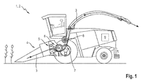
- Fig. 1 is a schematic side view of a running as a forage harvester 2 self-propelled harvester 1 shown in the crop on the field.
- the forage harvester 2 harvests or picks 4 plants from the field by means of an attachment 4 to the crop 3 obtained in the form of a Erntegutstroms (in Fig. 1 as indicated by arrows line) by working organs, which are designed as processing and conveying organs of the forage harvester 2, to lead and dump by means of a transfer device in a - not shown - loading container.
- the processing and conveying elements of the forage harvester 2 include, inter alia, a retraction member 5, which consists of several, in a feeder housing successively arranged pairs of rollers.
- a chopper 6, the comminuted by means of a rotating, equipped with knives chopper the crop in cooperation with a counter blade, one of the chaff 6 in a feed chute in Gutstromraum downstream conditioning 7 and one of the conditioning 7 in the feed chute downstream in Gutstromraum ejection accelerator 8, which the Crop material 3 is accelerated by means of rotating throw paddles for safe ejection through the transfer device.
- the attachment 4, the intake member 5, the chopper 6, the conditioning device 7 and the ejection accelerator 8 are hereinafter referred to as working organs.
- an internal combustion engine 9 is arranged, which serves the drive aforementioned work organs 4, 5, 6, 7, 8 of the forage harvester 2.
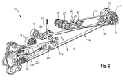
- Fig. 2 is a schematic view of a drive system 10 of the invention as a forage harvester 2 running harvester 1 shown.
- a transfer case 11 is driven by an output shaft.
- the transfer case 11 comprises a first driven pulley 12 and a second driven pulley 13, in particular as shown in FIG Fig. 3 , the one schematic partial view of the drive system 10 according to Fig. 2 from above, it can be seen.
- the first driven pulley 12 and the second driven pulley 13 are arranged coaxially with each other on an output shaft of the transfer case 11.
- the first driven pulley 12 is wrapped by a first belt 14, which wraps around a first drive pulley 16, which serves to drive the chopping device 6.
- the first drive pulley 16 are followed by a guide roller 19 and a second drive pulley 17.
- the first driven pulley 12, the first drive pulley 16 of the chopper 6, the second drive pulley 17 of the downstream ejection accelerator 8 and the first belt 14 form a main drive train, the direct mechanical drive of the chopping device 6 downstream in Gutstromraum working elements, the conditioning device 7 and the ejection accelerator 8 serves.
- a so-called load strand 15 extends between the first driven pulley 12 and the first drive pulley 16 of the chopper 6.
- the pulling direction is indicated by an arrow marked ZR.
- the guide roller 19 and a tensioning device 20 which acts on the first belt 14 by means of a tension roller 19a, the first belt 14 is guided and applied for the transmission of the drive power from the transfer case 11 on the working members 4, 5, 6, 7, 8 necessary belt tension.
- the drive of the chaffing device 6 in Gutstromraum upstream work organs, the attachment 4 and the retraction member 5 is carried by separate hydraulic motors 21 a and 21 b, arranged at the respective output shaft a propeller shaft 22a and 22b for transmitting the torque to the attachment 4 and the retraction member 5 are.
- the hydraulic motor 21 a of the retraction member 5 and the hydraulic motor 21 b of the attachment 4 are fed by a respective connected to these by a (not shown) hydraulic line first hydraulic pump 23 and second hydraulic pump 24.
- first hydraulic pump 23 and the second hydraulic pump 24 are designed as a so-called tandem pump.
- the first hydraulic pump 23 is connected via its drive shaft with the first Pump drive pulley 28 drivingly.
- the recorded by the drive shaft of the first hydraulic pump 23 line is used to a part for driving the hydraulic motor 21 a of the retraction member 5, to another part, the power absorbed the drive of the second hydraulic pump 24, which in turn the hydraulic motor 21 b of the attachment. 4 fed.
- the arrangement of the second, the hydraulic motor 21 a of the intake 5 feeding hydraulic pump 24 on the first pump drive pulley 28 remote from the side is required to stop in the event of detection of a foreign body in the retraction member 5 this immediately. This is done by interrupting the delivery of hydraulic oil from the second hydraulic pump 24 to the hydraulic motor 21 b by means of a control valve assembly to the hydraulic motor 21 b.
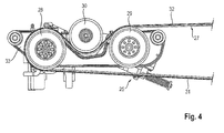
- the first hydraulic pump 23 and the second hydraulic pump 24 are driven by a belt drive comprising a second belt 27 that wraps around the second output pulley 13 and a first pump drive pulley 28 and a second pump drive pulley 29, as shown in FIG Fig. 4 in which a partial schematic view of the drive system according to Fig. 3 shown from the side is shown.
- the second driven pulley 13, the first pump driving pulley 28, and the second pump driving pulley 29 constitute a sub-drive train which serves to drive at least the first and second hydraulic pumps 23 and 24.
- the second pump drive pulley 29 is disposed downstream of the first pump drive pulley 28.
- the second pump drive pulley 29 drives a third hydraulic pump 26.
- a tension roller 30, which is coupled to the tensioning device 25, is arranged.
- the first hydraulic pump 23, the second hydraulic pump 24 and the third hydraulic pump 26 are arranged on a common bracket 33.
- the third hydraulic pump 26 is used in the present embodiment, the drive of a hydraulic Aufsammelantriebes a running as a pick-up attachment 4.
- the operation of the third hydraulic pump 26 is accordingly only required for operation of the forage harvester with a pick-up as mounted attachment.
- the third hydraulic pump 26 can be decoupled from the auxiliary drive train by means of a coupling between the drive shaft of the third hydraulic pump 26 and the second pump drive pulley 29.
- the third hydraulic pump 26 can serve as a drive for a component of a header designed as a grain cutter, which can be coupled to the forage harvester 2.
- Second belt 2 Forage First pump drive pulley 3 crop 29 Second pump drive pulley 4 header 30 idler pulley 5 feeder organ 31 load strand 6 chopper 32 loose side 7 conditioning device 33 console 8th discharge accelerator 9 internal combustion engine 10 drive system 11 Transfer Case 12 First output pulley 13 Second driven pulley 14 First strap 15 load strand 16 First drive pulley 17 Second drive pulley 18 loose side 19 idler pulley 19a idler 20 tensioning device 21a hydraulic motor 21b hydraulic motor 22a propeller shaft 22b propeller shaft 23 First hydraulic pump 24 Second hydraulic pump 25 tensioning device 26 Third hydraulic pump
Landscapes
- Life Sciences & Earth Sciences (AREA)
- Environmental Sciences (AREA)
- Engineering & Computer Science (AREA)
- General Engineering & Computer Science (AREA)
- Mechanical Engineering (AREA)
- Harvester Elements (AREA)
Applications Claiming Priority (1)
| Application Number | Priority Date | Filing Date | Title |
|---|---|---|---|
| DE102014108026.2A DE102014108026A1 (de) | 2014-06-06 | 2014-06-06 | Antriebssystem für eine selbstfahrende Erntemaschine |
Publications (2)
| Publication Number | Publication Date |
|---|---|
| EP2952087A1 true EP2952087A1 (fr) | 2015-12-09 |
| EP2952087B1 EP2952087B1 (fr) | 2017-11-01 |
Family
ID=52669542
Family Applications (1)
| Application Number | Title | Priority Date | Filing Date |
|---|---|---|---|
| EP15159128.6A Active EP2952087B1 (fr) | 2014-06-06 | 2015-03-16 | Système d'entraînement d'une moissonneuse automotrice |
Country Status (3)
| Country | Link |
|---|---|
| US (1) | US9635812B2 (fr) |
| EP (1) | EP2952087B1 (fr) |
| DE (1) | DE102014108026A1 (fr) |
Cited By (1)
| Publication number | Priority date | Publication date | Assignee | Title |
|---|---|---|---|---|
| EP4295668A1 (fr) * | 2022-06-24 | 2023-12-27 | Maschinenfabrik Bernard Krone GmbH & Co. KG | Dispositif d'alimentation pour une machine agricole |
Families Citing this family (9)
| Publication number | Priority date | Publication date | Assignee | Title |
|---|---|---|---|---|
| DE102014107921A1 (de) * | 2014-06-05 | 2015-12-17 | Claas Selbstfahrende Erntemaschinen Gmbh | Antriebssystem für eine selbstfahrende Erntemaschine |
| US10492363B2 (en) * | 2015-11-20 | 2019-12-03 | Tribine Industries Llc | Rear grain cart handling assemblies for an articulated harvesting combine |
| US11248680B2 (en) * | 2018-11-28 | 2022-02-15 | Deere & Company | System and method to reduce parasitic loads on an engine of a harvesting machine |
| DE102020111992A1 (de) | 2020-05-04 | 2021-11-04 | Claas Selbstfahrende Erntemaschinen Gmbh | Antriebssystem für eine selbstfahrende Erntemaschine |
| DE102020111993A1 (de) | 2020-05-04 | 2021-11-04 | Claas Selbstfahrende Erntemaschinen Gmbh | Antriebssystem für eine selbstfahrende Erntemaschine |
| CN113950959B (zh) * | 2021-10-15 | 2023-04-25 | 新疆新研牧神科技有限公司 | 传动系统及青贮机 |
| CN115380694B (zh) * | 2022-07-28 | 2023-09-22 | 农业农村部南京农业机械化研究所 | 一种收获机用紧凑型多输出驱动系统及农作物根果收获机 |
| DE102023106857A1 (de) | 2023-03-20 | 2024-09-26 | Claas Selbstfahrende Erntemaschinen Gmbh | Erntemaschine |
| DE102024122298A1 (de) * | 2024-08-05 | 2026-02-05 | Claas Selbstfahrende Erntemaschinen Gmbh | Landwirtschaftliche Arbeitsmaschine |
Citations (8)
| Publication number | Priority date | Publication date | Assignee | Title |
|---|---|---|---|---|
| GB703617A (en) * | 1950-05-10 | 1954-02-10 | Minneapolis Moline Co | Improvements in or relating to agricultural tractors |
| DE1221480B (de) * | 1958-06-24 | 1966-07-21 | Massey Ferguson Services Nv | Selbstfahrender Maehdrescher |
| DE102004042113A1 (de) * | 2004-08-30 | 2006-04-06 | Claas Selbstfahrende Erntemaschinen Gmbh | Antrieb einer Zuführvorrichtung für landwirtschaftliche Arbeitsmaschinen |
| US20060272496A1 (en) * | 2005-05-18 | 2006-12-07 | Ryota Ohashi | HST unit |
| EP1875933A1 (fr) | 2006-07-06 | 2008-01-09 | Debiotech S.A. | Dispositif médical pour l'administration d'une solution |
| WO2008053607A1 (fr) * | 2006-11-02 | 2008-05-08 | Yanmar Co., Ltd. | Engin de travaux de type agricole |
| DE102009028056A1 (de) * | 2008-08-12 | 2010-02-18 | Deere & Company, Moline | Selbstfahrende Erntemaschine |
| WO2013018696A1 (fr) * | 2011-08-02 | 2013-02-07 | ヤンマー株式会社 | Moissonneuse-batteuse |
Family Cites Families (30)
| Publication number | Priority date | Publication date | Assignee | Title |
|---|---|---|---|---|
| US4455812A (en) * | 1983-01-24 | 1984-06-26 | Allis-Chalmers Corp. | Combine drive with double clutch assembly |
| EP0222929B1 (fr) * | 1985-11-22 | 1989-11-08 | Deere & Company | Variateur continu de vitesse à courroie |
| US4967863A (en) * | 1987-05-15 | 1990-11-06 | Deere & Company | Compact combine drive system |
| GB2289201A (en) * | 1994-05-07 | 1995-11-15 | Ford New Holland Nv | Drive reversal for agricultural harvester |
| DE19918550A1 (de) * | 1999-04-23 | 2000-10-26 | Deere & Co | Antriebseinrichtung der Förder- und/oder Gutbearbeitungsvorrichtung einer Erntemaschine |
| US6131837A (en) * | 1999-07-28 | 2000-10-17 | New Holland North America, Inc. | Segmented crop processor roll for forage harvester |
| GB9926580D0 (en) * | 1999-11-11 | 2000-01-12 | Medicine | Crop processor and blower arrangement for a forage harvester |
| US6722112B2 (en) * | 2002-02-28 | 2004-04-20 | Deere & Company | Reverser control for a combine |
| DE10220699A1 (de) * | 2002-05-10 | 2003-12-24 | Deere & Co | Vorrichtung zur Einstellung der Schnittlänge einer Häckseleinrichtung |
| GB0212649D0 (en) * | 2002-05-31 | 2002-07-10 | Ford New Holland Nv | Utility machinery and associated reversible feeder mechanisms |
| DE10245885A1 (de) * | 2002-09-30 | 2004-04-08 | Deere & Company, Moline | Erntemaschine |
| DE102004029953A1 (de) * | 2004-06-21 | 2006-01-12 | Deere & Company, Moline | Erntevorsatzantrieb |
| EP1671530B1 (fr) * | 2004-12-18 | 2008-01-16 | Deere & Company | Machine de récolte |
| DE102005031549A1 (de) * | 2005-07-06 | 2007-01-25 | Deere & Company, Moline | Feldhäcksler und Verfahren zum Betrieb |
| US7614970B2 (en) * | 2005-07-29 | 2009-11-10 | Deere & Company | Torque sensing assembly having dual stage spring compression for an agricultural machine |
| DE102006030971A1 (de) | 2006-07-03 | 2008-01-17 | Claas Selbstfahrende Erntemaschinen Gmbh | Antriebssystem einer landwirtschaftlichen Arbeitsmaschine |
| DE102008009447B4 (de) * | 2008-02-15 | 2015-11-19 | Deere & Company | Selbstfahrende landwirtschaftliche Erntemaschine mit zwei Verbrennungsmotoren |
| DE102009002849A1 (de) * | 2008-07-11 | 2010-01-14 | Deere & Company, Moline | Antriebssystem für einen Einzugsförderer einer Erntemaschine |
| BE1018656A3 (nl) * | 2009-02-13 | 2011-06-07 | Cnh Belgium Nv | Een hakselaar met een blazer. |
| DE102009028175A1 (de) * | 2009-02-27 | 2010-09-02 | Deere & Company, Moline | Selbstfahrende Erntemaschine |
| JP5249888B2 (ja) * | 2009-09-24 | 2013-07-31 | 株式会社クボタ | 刈取収穫機の走行変速装置 |
| DE102009047343A1 (de) * | 2009-12-01 | 2011-06-09 | Deere & Company, Moline | Antriebsanordnung und Verfahren für eine Arbeitsmaschine mit zwei Verbrennungsmotoren |
| DE102010002730B4 (de) * | 2010-03-10 | 2015-12-24 | Deere & Company | Erntemaschine mit einer Transporteinrichtung für den Ein- und Ausbau einer Erntegutbearbeitungseinrichtung |
| KR101936448B1 (ko) * | 2011-03-31 | 2019-01-08 | 가부시끼 가이샤 구보다 | 변속 전동 장치 및 주행 전동 장치 |
| US8978796B2 (en) * | 2012-01-06 | 2015-03-17 | Silvio Gallazzini | Tractor having dual hydrostatic drive with single hand control and attachment adapter for powered attachments |
| US9556938B2 (en) * | 2012-11-28 | 2017-01-31 | Cnh Industrial America Llc | Belt drive having a speed selection shift mechanism |
| BE1021121B1 (nl) * | 2013-01-03 | 2016-02-15 | Cnh Industrial Belgium Nv | Een oogstmachine bevattende een stroschudderbesturingssysteem |
| DE102013103450A1 (de) * | 2013-04-08 | 2014-10-09 | Claas Selbstfahrende Erntemaschinen Gmbh | Als Riementriebe ausgebildetes Antriebssystem eines selbstfahrenden Mähdreschers |
| US9845857B2 (en) * | 2013-09-27 | 2017-12-19 | Kubota Corporation | Combine |
| DE102014107921A1 (de) * | 2014-06-05 | 2015-12-17 | Claas Selbstfahrende Erntemaschinen Gmbh | Antriebssystem für eine selbstfahrende Erntemaschine |
-
2014
- 2014-06-06 DE DE102014108026.2A patent/DE102014108026A1/de not_active Withdrawn
-
2015
- 2015-03-16 EP EP15159128.6A patent/EP2952087B1/fr active Active
- 2015-06-03 US US14/729,503 patent/US9635812B2/en not_active Expired - Fee Related
Patent Citations (8)
| Publication number | Priority date | Publication date | Assignee | Title |
|---|---|---|---|---|
| GB703617A (en) * | 1950-05-10 | 1954-02-10 | Minneapolis Moline Co | Improvements in or relating to agricultural tractors |
| DE1221480B (de) * | 1958-06-24 | 1966-07-21 | Massey Ferguson Services Nv | Selbstfahrender Maehdrescher |
| DE102004042113A1 (de) * | 2004-08-30 | 2006-04-06 | Claas Selbstfahrende Erntemaschinen Gmbh | Antrieb einer Zuführvorrichtung für landwirtschaftliche Arbeitsmaschinen |
| US20060272496A1 (en) * | 2005-05-18 | 2006-12-07 | Ryota Ohashi | HST unit |
| EP1875933A1 (fr) | 2006-07-06 | 2008-01-09 | Debiotech S.A. | Dispositif médical pour l'administration d'une solution |
| WO2008053607A1 (fr) * | 2006-11-02 | 2008-05-08 | Yanmar Co., Ltd. | Engin de travaux de type agricole |
| DE102009028056A1 (de) * | 2008-08-12 | 2010-02-18 | Deere & Company, Moline | Selbstfahrende Erntemaschine |
| WO2013018696A1 (fr) * | 2011-08-02 | 2013-02-07 | ヤンマー株式会社 | Moissonneuse-batteuse |
Cited By (1)
| Publication number | Priority date | Publication date | Assignee | Title |
|---|---|---|---|---|
| EP4295668A1 (fr) * | 2022-06-24 | 2023-12-27 | Maschinenfabrik Bernard Krone GmbH & Co. KG | Dispositif d'alimentation pour une machine agricole |
Also Published As
| Publication number | Publication date |
|---|---|
| DE102014108026A1 (de) | 2015-12-17 |
| US9635812B2 (en) | 2017-05-02 |
| EP2952087B1 (fr) | 2017-11-01 |
| US20150351324A1 (en) | 2015-12-10 |
Similar Documents
| Publication | Publication Date | Title |
|---|---|---|
| EP2952087B1 (fr) | Système d'entraînement d'une moissonneuse automotrice | |
| EP2404496B2 (fr) | Cueilleur à maïs | |
| DE102014219049B4 (de) | Feldhäcksler mit reversierbarer Konditioniereinrichtung | |
| BE1026188B1 (de) | Feldhäcksler mit schnittlängenabhängiger Drehzahl der Konditioniereinrichtung | |
| EP3906770B1 (fr) | Système d'entraînement pour un engin d'abattage-façonnage autonome | |
| EP2789222A1 (fr) | Système d'entraînement configuré sous forme d'entraînement à courroie d'une moissonneuse-batteuse automotrice | |
| EP1243173A1 (fr) | Convoyeur élévateur muni d'un capteur de force pour détecter le débit d'une moissonneuse-batteuse | |
| DE102012106603A1 (de) | Reihenunabhängig arbeitendes Vorsatzgerät zum Ernten von stängeligem Erntegut | |
| DE102009035691A1 (de) | Voratzgerät mit Querfördereinrichtung und Drehzahlanpassung | |
| DE102012101807A1 (de) | Selbstfahrende Erntemaschine | |
| BE1029376B1 (de) | Antriebsanordnung einer Konditioniereinrichtung eines Feldhäckslers mit einem elektrischen Antriebsstrang | |
| EP1875793A1 (fr) | Système de propulsion d'une machine de travail agricole | |
| DE102013108923A1 (de) | Mähdrescher mit einer Häckselvorrichtung | |
| DE102016211570B4 (de) | Antriebsanordnung zum drehzahlveränderbaren Antrieb einer mit zwei Konditionierwalzen ausgestatteten Konditioniereinrichtung eines Feldhäckslers | |
| EP2952088B1 (fr) | Système d'entraînement d'une moissonneuse automotrice | |
| DE102016103204A1 (de) | Antriebsanordnung für einen Mähdrescher | |
| DE202011002195U1 (de) | Selbstfahrende landwirtschaftliche Erntemaschine mit einem elektromotorisch angetriebenen Arbeitsorgan | |
| EP1632131A1 (fr) | Système d'entraînement d'un dispositif d'alimentation pour une machine agricole | |
| DE102006030954B4 (de) | Antriebssystem einer landwirtschaftlichen Arbeitsmaschine | |
| EP3714676B1 (fr) | Ramasseuse-hacheuse-chargeuse autonome ainsi que procédé de récolte au moyen d'une ramasseuse-hacheuse-chargeuse | |
| DE102021116753A1 (de) | Verfahren und Steuergerät zum Betreiben einer landwirtschaftlichen Erntemaschine sowie landwirtschaftliche Erntemaschine | |
| EP3906769B1 (fr) | Système d'entraînement pour un engin d'abattage-façonnage autonome | |
| EP4371393B1 (fr) | Moissonneuse automotrice | |
| DE102015100955A1 (de) | Selbstfahrende landwirtschaftliche Erntemaschine | |
| DE102023132967A1 (de) | Mähdrescher |
Legal Events
| Date | Code | Title | Description |
|---|---|---|---|
| PUAI | Public reference made under article 153(3) epc to a published international application that has entered the european phase |
Free format text: ORIGINAL CODE: 0009012 |
|
| AK | Designated contracting states |
Kind code of ref document: A1 Designated state(s): AL AT BE BG CH CY CZ DE DK EE ES FI FR GB GR HR HU IE IS IT LI LT LU LV MC MK MT NL NO PL PT RO RS SE SI SK SM TR |
|
| AX | Request for extension of the european patent |
Extension state: BA ME |
|
| 17P | Request for examination filed |
Effective date: 20160609 |
|
| RBV | Designated contracting states (corrected) |
Designated state(s): AL AT BE BG CH CY CZ DE DK EE ES FI FR GB GR HR HU IE IS IT LI LT LU LV MC MK MT NL NO PL PT RO RS SE SI SK SM TR |
|
| RAP1 | Party data changed (applicant data changed or rights of an application transferred) |
Owner name: CLAAS SELBSTFAHRENDE ERNTEMASCHINEN GMBH |
|
| GRAP | Despatch of communication of intention to grant a patent |
Free format text: ORIGINAL CODE: EPIDOSNIGR1 |
|
| RIC1 | Information provided on ipc code assigned before grant |
Ipc: A01D 69/00 20060101AFI20170615BHEP Ipc: A01D 43/08 20060101ALN20170615BHEP Ipc: A01D 69/03 20060101ALN20170615BHEP |
|
| RIC1 | Information provided on ipc code assigned before grant |
Ipc: A01D 69/00 20060101AFI20170705BHEP Ipc: A01D 43/08 20060101ALN20170705BHEP Ipc: A01D 69/03 20060101ALN20170705BHEP |
|
| INTG | Intention to grant announced |
Effective date: 20170718 |
|
| GRAS | Grant fee paid |
Free format text: ORIGINAL CODE: EPIDOSNIGR3 |
|
| GRAA | (expected) grant |
Free format text: ORIGINAL CODE: 0009210 |
|
| AK | Designated contracting states |
Kind code of ref document: B1 Designated state(s): AL AT BE BG CH CY CZ DE DK EE ES FI FR GB GR HR HU IE IS IT LI LT LU LV MC MK MT NL NO PL PT RO RS SE SI SK SM TR |
|
| REG | Reference to a national code |
Ref country code: GB Ref legal event code: FG4D Free format text: NOT ENGLISH |
|
| REG | Reference to a national code |
Ref country code: CH Ref legal event code: EP Ref country code: AT Ref legal event code: REF Ref document number: 941066 Country of ref document: AT Kind code of ref document: T Effective date: 20171115 |
|
| REG | Reference to a national code |
Ref country code: IE Ref legal event code: FG4D Free format text: LANGUAGE OF EP DOCUMENT: GERMAN |
|
| REG | Reference to a national code |
Ref country code: DE Ref legal event code: R096 Ref document number: 502015002225 Country of ref document: DE |
|
| REG | Reference to a national code |
Ref country code: NL Ref legal event code: MP Effective date: 20171101 |
|
| REG | Reference to a national code |
Ref country code: LT Ref legal event code: MG4D |
|
| PG25 | Lapsed in a contracting state [announced via postgrant information from national office to epo] |
Ref country code: ES Free format text: LAPSE BECAUSE OF FAILURE TO SUBMIT A TRANSLATION OF THE DESCRIPTION OR TO PAY THE FEE WITHIN THE PRESCRIBED TIME-LIMIT Effective date: 20171101 Ref country code: NL Free format text: LAPSE BECAUSE OF FAILURE TO SUBMIT A TRANSLATION OF THE DESCRIPTION OR TO PAY THE FEE WITHIN THE PRESCRIBED TIME-LIMIT Effective date: 20171101 Ref country code: SE Free format text: LAPSE BECAUSE OF FAILURE TO SUBMIT A TRANSLATION OF THE DESCRIPTION OR TO PAY THE FEE WITHIN THE PRESCRIBED TIME-LIMIT Effective date: 20171101 Ref country code: NO Free format text: LAPSE BECAUSE OF FAILURE TO SUBMIT A TRANSLATION OF THE DESCRIPTION OR TO PAY THE FEE WITHIN THE PRESCRIBED TIME-LIMIT Effective date: 20180201 Ref country code: FI Free format text: LAPSE BECAUSE OF FAILURE TO SUBMIT A TRANSLATION OF THE DESCRIPTION OR TO PAY THE FEE WITHIN THE PRESCRIBED TIME-LIMIT Effective date: 20171101 Ref country code: LT Free format text: LAPSE BECAUSE OF FAILURE TO SUBMIT A TRANSLATION OF THE DESCRIPTION OR TO PAY THE FEE WITHIN THE PRESCRIBED TIME-LIMIT Effective date: 20171101 |
|
| PG25 | Lapsed in a contracting state [announced via postgrant information from national office to epo] |
Ref country code: GR Free format text: LAPSE BECAUSE OF FAILURE TO SUBMIT A TRANSLATION OF THE DESCRIPTION OR TO PAY THE FEE WITHIN THE PRESCRIBED TIME-LIMIT Effective date: 20180202 Ref country code: LV Free format text: LAPSE BECAUSE OF FAILURE TO SUBMIT A TRANSLATION OF THE DESCRIPTION OR TO PAY THE FEE WITHIN THE PRESCRIBED TIME-LIMIT Effective date: 20171101 Ref country code: RS Free format text: LAPSE BECAUSE OF FAILURE TO SUBMIT A TRANSLATION OF THE DESCRIPTION OR TO PAY THE FEE WITHIN THE PRESCRIBED TIME-LIMIT Effective date: 20171101 Ref country code: HR Free format text: LAPSE BECAUSE OF FAILURE TO SUBMIT A TRANSLATION OF THE DESCRIPTION OR TO PAY THE FEE WITHIN THE PRESCRIBED TIME-LIMIT Effective date: 20171101 Ref country code: IS Free format text: LAPSE BECAUSE OF FAILURE TO SUBMIT A TRANSLATION OF THE DESCRIPTION OR TO PAY THE FEE WITHIN THE PRESCRIBED TIME-LIMIT Effective date: 20180301 Ref country code: BG Free format text: LAPSE BECAUSE OF FAILURE TO SUBMIT A TRANSLATION OF THE DESCRIPTION OR TO PAY THE FEE WITHIN THE PRESCRIBED TIME-LIMIT Effective date: 20180201 |
|
| PG25 | Lapsed in a contracting state [announced via postgrant information from national office to epo] |
Ref country code: SK Free format text: LAPSE BECAUSE OF FAILURE TO SUBMIT A TRANSLATION OF THE DESCRIPTION OR TO PAY THE FEE WITHIN THE PRESCRIBED TIME-LIMIT Effective date: 20171101 Ref country code: CZ Free format text: LAPSE BECAUSE OF FAILURE TO SUBMIT A TRANSLATION OF THE DESCRIPTION OR TO PAY THE FEE WITHIN THE PRESCRIBED TIME-LIMIT Effective date: 20171101 Ref country code: CY Free format text: LAPSE BECAUSE OF FAILURE TO SUBMIT A TRANSLATION OF THE DESCRIPTION OR TO PAY THE FEE WITHIN THE PRESCRIBED TIME-LIMIT Effective date: 20171101 Ref country code: DK Free format text: LAPSE BECAUSE OF FAILURE TO SUBMIT A TRANSLATION OF THE DESCRIPTION OR TO PAY THE FEE WITHIN THE PRESCRIBED TIME-LIMIT Effective date: 20171101 Ref country code: EE Free format text: LAPSE BECAUSE OF FAILURE TO SUBMIT A TRANSLATION OF THE DESCRIPTION OR TO PAY THE FEE WITHIN THE PRESCRIBED TIME-LIMIT Effective date: 20171101 |
|
| REG | Reference to a national code |
Ref country code: DE Ref legal event code: R097 Ref document number: 502015002225 Country of ref document: DE |
|
| PG25 | Lapsed in a contracting state [announced via postgrant information from national office to epo] |
Ref country code: PL Free format text: LAPSE BECAUSE OF FAILURE TO SUBMIT A TRANSLATION OF THE DESCRIPTION OR TO PAY THE FEE WITHIN THE PRESCRIBED TIME-LIMIT Effective date: 20171101 Ref country code: RO Free format text: LAPSE BECAUSE OF FAILURE TO SUBMIT A TRANSLATION OF THE DESCRIPTION OR TO PAY THE FEE WITHIN THE PRESCRIBED TIME-LIMIT Effective date: 20171101 Ref country code: SM Free format text: LAPSE BECAUSE OF FAILURE TO SUBMIT A TRANSLATION OF THE DESCRIPTION OR TO PAY THE FEE WITHIN THE PRESCRIBED TIME-LIMIT Effective date: 20171101 Ref country code: IT Free format text: LAPSE BECAUSE OF FAILURE TO SUBMIT A TRANSLATION OF THE DESCRIPTION OR TO PAY THE FEE WITHIN THE PRESCRIBED TIME-LIMIT Effective date: 20171101 |
|
| PLBE | No opposition filed within time limit |
Free format text: ORIGINAL CODE: 0009261 |
|
| STAA | Information on the status of an ep patent application or granted ep patent |
Free format text: STATUS: NO OPPOSITION FILED WITHIN TIME LIMIT |
|
| PG25 | Lapsed in a contracting state [announced via postgrant information from national office to epo] |
Ref country code: MT Free format text: LAPSE BECAUSE OF FAILURE TO SUBMIT A TRANSLATION OF THE DESCRIPTION OR TO PAY THE FEE WITHIN THE PRESCRIBED TIME-LIMIT Effective date: 20171101 |
|
| 26N | No opposition filed |
Effective date: 20180802 |
|
| REG | Reference to a national code |
Ref country code: CH Ref legal event code: PL |
|
| PG25 | Lapsed in a contracting state [announced via postgrant information from national office to epo] |
Ref country code: MC Free format text: LAPSE BECAUSE OF FAILURE TO SUBMIT A TRANSLATION OF THE DESCRIPTION OR TO PAY THE FEE WITHIN THE PRESCRIBED TIME-LIMIT Effective date: 20171101 Ref country code: SI Free format text: LAPSE BECAUSE OF FAILURE TO SUBMIT A TRANSLATION OF THE DESCRIPTION OR TO PAY THE FEE WITHIN THE PRESCRIBED TIME-LIMIT Effective date: 20171101 |
|
| REG | Reference to a national code |
Ref country code: IE Ref legal event code: MM4A |
|
| PG25 | Lapsed in a contracting state [announced via postgrant information from national office to epo] |
Ref country code: LU Free format text: LAPSE BECAUSE OF NON-PAYMENT OF DUE FEES Effective date: 20180316 |
|
| PG25 | Lapsed in a contracting state [announced via postgrant information from national office to epo] |
Ref country code: IE Free format text: LAPSE BECAUSE OF NON-PAYMENT OF DUE FEES Effective date: 20180316 |
|
| PG25 | Lapsed in a contracting state [announced via postgrant information from national office to epo] |
Ref country code: CH Free format text: LAPSE BECAUSE OF NON-PAYMENT OF DUE FEES Effective date: 20180331 Ref country code: LI Free format text: LAPSE BECAUSE OF NON-PAYMENT OF DUE FEES Effective date: 20180331 |
|
| PG25 | Lapsed in a contracting state [announced via postgrant information from national office to epo] |
Ref country code: FR Free format text: LAPSE BECAUSE OF NON-PAYMENT OF DUE FEES Effective date: 20180331 |
|
| GBPC | Gb: european patent ceased through non-payment of renewal fee |
Effective date: 20190316 |
|
| PG25 | Lapsed in a contracting state [announced via postgrant information from national office to epo] |
Ref country code: GB Free format text: LAPSE BECAUSE OF NON-PAYMENT OF DUE FEES Effective date: 20190316 |
|
| PG25 | Lapsed in a contracting state [announced via postgrant information from national office to epo] |
Ref country code: TR Free format text: LAPSE BECAUSE OF FAILURE TO SUBMIT A TRANSLATION OF THE DESCRIPTION OR TO PAY THE FEE WITHIN THE PRESCRIBED TIME-LIMIT Effective date: 20171101 |
|
| PG25 | Lapsed in a contracting state [announced via postgrant information from national office to epo] |
Ref country code: PT Free format text: LAPSE BECAUSE OF FAILURE TO SUBMIT A TRANSLATION OF THE DESCRIPTION OR TO PAY THE FEE WITHIN THE PRESCRIBED TIME-LIMIT Effective date: 20171101 |
|
| PG25 | Lapsed in a contracting state [announced via postgrant information from national office to epo] |
Ref country code: MK Free format text: LAPSE BECAUSE OF NON-PAYMENT OF DUE FEES Effective date: 20171101 Ref country code: HU Free format text: LAPSE BECAUSE OF FAILURE TO SUBMIT A TRANSLATION OF THE DESCRIPTION OR TO PAY THE FEE WITHIN THE PRESCRIBED TIME-LIMIT; INVALID AB INITIO Effective date: 20150316 |
|
| PG25 | Lapsed in a contracting state [announced via postgrant information from national office to epo] |
Ref country code: AL Free format text: LAPSE BECAUSE OF FAILURE TO SUBMIT A TRANSLATION OF THE DESCRIPTION OR TO PAY THE FEE WITHIN THE PRESCRIBED TIME-LIMIT Effective date: 20171101 |
|
| REG | Reference to a national code |
Ref country code: AT Ref legal event code: MM01 Ref document number: 941066 Country of ref document: AT Kind code of ref document: T Effective date: 20200316 |
|
| PG25 | Lapsed in a contracting state [announced via postgrant information from national office to epo] |
Ref country code: AT Free format text: LAPSE BECAUSE OF NON-PAYMENT OF DUE FEES Effective date: 20200316 |
|
| P01 | Opt-out of the competence of the unified patent court (upc) registered |
Effective date: 20230515 |
|
| PGFP | Annual fee paid to national office [announced via postgrant information from national office to epo] |
Ref country code: DE Payment date: 20260319 Year of fee payment: 12 |
|
| PGFP | Annual fee paid to national office [announced via postgrant information from national office to epo] |
Ref country code: BE Payment date: 20260319 Year of fee payment: 12 |