EP2952137A1 - Ultraschallbildgebungsvorrichtung und ultraschallbildgebungsverfahren - Google Patents
Ultraschallbildgebungsvorrichtung und ultraschallbildgebungsverfahren Download PDFInfo
- Publication number
- EP2952137A1 EP2952137A1 EP14746526.4A EP14746526A EP2952137A1 EP 2952137 A1 EP2952137 A1 EP 2952137A1 EP 14746526 A EP14746526 A EP 14746526A EP 2952137 A1 EP2952137 A1 EP 2952137A1
- Authority
- EP
- European Patent Office
- Prior art keywords
- amplification
- transmission
- modulated
- echo
- amplitude
- Prior art date
- Legal status (The legal status is an assumption and is not a legal conclusion. Google has not performed a legal analysis and makes no representation as to the accuracy of the status listed.)
- Withdrawn
Links
Images





Classifications
-
- G—PHYSICS
- G01—MEASURING; TESTING
- G01S—RADIO DIRECTION-FINDING; RADIO NAVIGATION; DETERMINING DISTANCE OR VELOCITY BY USE OF RADIO WAVES; LOCATING OR PRESENCE-DETECTING BY USE OF THE REFLECTION OR RERADIATION OF RADIO WAVES; ANALOGOUS ARRANGEMENTS USING OTHER WAVES
- G01S7/00—Details of systems according to groups G01S13/00, G01S15/00, G01S17/00
- G01S7/52—Details of systems according to groups G01S13/00, G01S15/00, G01S17/00 of systems according to group G01S15/00
- G01S7/52017—Details of systems according to groups G01S13/00, G01S15/00, G01S17/00 of systems according to group G01S15/00 particularly adapted to short-range imaging
- G01S7/52019—Details of transmitters
- G01S7/5202—Details of transmitters for pulse systems
-
- G—PHYSICS
- G01—MEASURING; TESTING
- G01S—RADIO DIRECTION-FINDING; RADIO NAVIGATION; DETERMINING DISTANCE OR VELOCITY BY USE OF RADIO WAVES; LOCATING OR PRESENCE-DETECTING BY USE OF THE REFLECTION OR RERADIATION OF RADIO WAVES; ANALOGOUS ARRANGEMENTS USING OTHER WAVES
- G01S15/00—Systems using the reflection or reradiation of acoustic waves, e.g. sonar systems
- G01S15/88—Sonar systems specially adapted for specific applications
- G01S15/89—Sonar systems specially adapted for specific applications for mapping or imaging
- G01S15/8906—Short-range imaging systems; Acoustic microscope systems using pulse-echo techniques
-
- A—HUMAN NECESSITIES
- A61—MEDICAL OR VETERINARY SCIENCE; HYGIENE
- A61B—DIAGNOSIS; SURGERY; IDENTIFICATION
- A61B8/00—Diagnosis using ultrasonic, sonic or infrasonic waves
- A61B8/13—Tomography
- A61B8/14—Echo-tomography
- A61B8/145—Echo-tomography characterised by scanning multiple planes
-
- A—HUMAN NECESSITIES
- A61—MEDICAL OR VETERINARY SCIENCE; HYGIENE
- A61B—DIAGNOSIS; SURGERY; IDENTIFICATION
- A61B8/00—Diagnosis using ultrasonic, sonic or infrasonic waves
- A61B8/44—Constructional features of the ultrasonic, sonic or infrasonic diagnostic device
- A61B8/4483—Constructional features of the ultrasonic, sonic or infrasonic diagnostic device characterised by features of the ultrasound transducer
-
- A—HUMAN NECESSITIES
- A61—MEDICAL OR VETERINARY SCIENCE; HYGIENE
- A61B—DIAGNOSIS; SURGERY; IDENTIFICATION
- A61B8/00—Diagnosis using ultrasonic, sonic or infrasonic waves
- A61B8/52—Devices using data or image processing specially adapted for diagnosis using ultrasonic, sonic or infrasonic waves
- A61B8/5207—Devices using data or image processing specially adapted for diagnosis using ultrasonic, sonic or infrasonic waves involving processing of raw data to produce diagnostic data, e.g. for generating an image
-
- A—HUMAN NECESSITIES
- A61—MEDICAL OR VETERINARY SCIENCE; HYGIENE
- A61B—DIAGNOSIS; SURGERY; IDENTIFICATION
- A61B8/00—Diagnosis using ultrasonic, sonic or infrasonic waves
- A61B8/54—Control of the diagnostic device
-
- G—PHYSICS
- G01—MEASURING; TESTING
- G01S—RADIO DIRECTION-FINDING; RADIO NAVIGATION; DETERMINING DISTANCE OR VELOCITY BY USE OF RADIO WAVES; LOCATING OR PRESENCE-DETECTING BY USE OF THE REFLECTION OR RERADIATION OF RADIO WAVES; ANALOGOUS ARRANGEMENTS USING OTHER WAVES
- G01S15/00—Systems using the reflection or reradiation of acoustic waves, e.g. sonar systems
- G01S15/88—Sonar systems specially adapted for specific applications
- G01S15/89—Sonar systems specially adapted for specific applications for mapping or imaging
- G01S15/8906—Short-range imaging systems; Acoustic microscope systems using pulse-echo techniques
- G01S15/8909—Short-range imaging systems; Acoustic microscope systems using pulse-echo techniques using a static transducer configuration
- G01S15/8915—Short-range imaging systems; Acoustic microscope systems using pulse-echo techniques using a static transducer configuration using a transducer array
-
- G—PHYSICS
- G01—MEASURING; TESTING
- G01S—RADIO DIRECTION-FINDING; RADIO NAVIGATION; DETERMINING DISTANCE OR VELOCITY BY USE OF RADIO WAVES; LOCATING OR PRESENCE-DETECTING BY USE OF THE REFLECTION OR RERADIATION OF RADIO WAVES; ANALOGOUS ARRANGEMENTS USING OTHER WAVES
- G01S15/00—Systems using the reflection or reradiation of acoustic waves, e.g. sonar systems
- G01S15/88—Sonar systems specially adapted for specific applications
- G01S15/89—Sonar systems specially adapted for specific applications for mapping or imaging
- G01S15/8906—Short-range imaging systems; Acoustic microscope systems using pulse-echo techniques
- G01S15/8909—Short-range imaging systems; Acoustic microscope systems using pulse-echo techniques using a static transducer configuration
- G01S15/8915—Short-range imaging systems; Acoustic microscope systems using pulse-echo techniques using a static transducer configuration using a transducer array
- G01S15/8927—Short-range imaging systems; Acoustic microscope systems using pulse-echo techniques using a static transducer configuration using a transducer array using simultaneously or sequentially two or more subarrays or subapertures
-
- G—PHYSICS
- G01—MEASURING; TESTING
- G01S—RADIO DIRECTION-FINDING; RADIO NAVIGATION; DETERMINING DISTANCE OR VELOCITY BY USE OF RADIO WAVES; LOCATING OR PRESENCE-DETECTING BY USE OF THE REFLECTION OR RERADIATION OF RADIO WAVES; ANALOGOUS ARRANGEMENTS USING OTHER WAVES
- G01S7/00—Details of systems according to groups G01S13/00, G01S15/00, G01S17/00
- G01S7/52—Details of systems according to groups G01S13/00, G01S15/00, G01S17/00 of systems according to group G01S15/00
- G01S7/52017—Details of systems according to groups G01S13/00, G01S15/00, G01S17/00 of systems according to group G01S15/00 particularly adapted to short-range imaging
- G01S7/52023—Details of receivers
- G01S7/52033—Gain control of receivers
-
- G—PHYSICS
- G01—MEASURING; TESTING
- G01S—RADIO DIRECTION-FINDING; RADIO NAVIGATION; DETERMINING DISTANCE OR VELOCITY BY USE OF RADIO WAVES; LOCATING OR PRESENCE-DETECTING BY USE OF THE REFLECTION OR RERADIATION OF RADIO WAVES; ANALOGOUS ARRANGEMENTS USING OTHER WAVES
- G01S7/00—Details of systems according to groups G01S13/00, G01S15/00, G01S17/00
- G01S7/52—Details of systems according to groups G01S13/00, G01S15/00, G01S17/00 of systems according to group G01S15/00
- G01S7/52017—Details of systems according to groups G01S13/00, G01S15/00, G01S17/00 of systems according to group G01S15/00 particularly adapted to short-range imaging
- G01S7/52023—Details of receivers
- G01S7/52036—Details of receivers using analysis of echo signal for target characterisation
- G01S7/52038—Details of receivers using analysis of echo signal for target characterisation involving non-linear properties of the propagation medium or of the reflective target
-
- G—PHYSICS
- G01—MEASURING; TESTING
- G01S—RADIO DIRECTION-FINDING; RADIO NAVIGATION; DETERMINING DISTANCE OR VELOCITY BY USE OF RADIO WAVES; LOCATING OR PRESENCE-DETECTING BY USE OF THE REFLECTION OR RERADIATION OF RADIO WAVES; ANALOGOUS ARRANGEMENTS USING OTHER WAVES
- G01S7/00—Details of systems according to groups G01S13/00, G01S15/00, G01S17/00
- G01S7/52—Details of systems according to groups G01S13/00, G01S15/00, G01S17/00 of systems according to group G01S15/00
- G01S7/52017—Details of systems according to groups G01S13/00, G01S15/00, G01S17/00 of systems according to group G01S15/00 particularly adapted to short-range imaging
- G01S7/52046—Techniques for image enhancement involving transmitter or receiver
- G01S7/52047—Techniques for image enhancement involving transmitter or receiver for elimination of side lobes or of grating lobes; for increasing resolving power
Definitions
- the present invention relates to an imaging technique in an ultrasonic imaging apparatus, and in particular, to a nonlinear imaging technique.
- image data and time-series data are generated based on the reflected wave (echo) of an ultrasonic wave emitted to an object. Since ultrasonic waves are partially reflected on a boundary where the acoustic impedance is different while propagating through the object, echo having amplitude depending on the impedance difference is generated. Accordingly, the boundary surface can be displayed as a tomographic image of the object. In this case, waveform distortion occurs due to the characteristics that the ultrasonic wave propagates faster in a portion with high sound pressure and propagates slowly in a portion with low sound pressure.
- tissue harmonic imaging TTI
- the fundamental wave component is proportional to the amplitude
- the nonlinear component generated as a waveform distortion component is proportional to the square of the amplitude of the transmitted fundamental wave sound pressure.
- the amplitude modulation method is a method of canceling the fundamental wave component using this.
- the sound pressure level (amplitude) of the second transmission is set to 1/k (k is an integer of 1 or more) of the first transmission, and the echo is multiplied by k and the result is subtracted from the echo of the first transmission, thereby obtaining a reception signal (reception beam) excluding the fundamental wave component.
- amplitude modulation method In the amplitude modulation method, as described above, two types of ultrasonic waves having the same waveform and different sound pressure levels (amplitudes) (one of the sound pressure levels is k times the other sound pressure level) are transmitted, echoes of the two ultrasonic waves are received, and the nonlinear component is extracted by arithmetic processing. Before the arithmetic processing, each is converted into an electrical signal (echo signal), and is amplified by a pre-amplifier or the like in an analog circuit. In general, in the amplifier, a range in which the linearity of the output voltage with respect to the input voltage (linear range) can be maintained is limited. Accordingly, when an input signal with a voltage larger than the linear range passes through the pre-amplifier, the waveform of the output signal is distorted or saturated (clipped).
- the amplitude modulation method when used, only the echo obtained corresponding to the ultrasonic wave having larger amplitude may exceed the linear range of the amplifier, and the waveform may be distorted or clipped.
- the amplitude ratio of two echo signals after passing through the pre-amplifier is not the same as the amplitude ratio at the time of transmission.
- a calculation is performed on the assumption that the amplitude ratio of two reception signals is the same as an amplitude ratio at the time of transmission. Therefore, since it is not possible to perform a calculation correctly, it is not possible to extract a nonlinear component with high accuracy from the reception beam finally (echo signal) obtained.
- the present invention has been made in view of the aforementioned situation, and it is an object of the present invention to provide a technique for obtaining a high-quality image by extracting only a nonlinear component with high accuracy in ultrasonic imaging using the amplitude modulation method of the THI.
- the influence of electrical distortion of the signal waveform to the two echo signals having different sound pressure levels due to analog amplification are formed to be approximately equal to each other. And then, a nonlinear component is extracted with high accuracy
- an ultrasonic imaging apparatus including: a transmission unit that transmits an ultrasonic beam multiple times to a predetermined position of an imaging target through an ultrasonic probe; a reception processing unit that receives an echo of the ultrasonic beam from the imaging target through the ultrasonic probe in a channel unit set in advance and extracts a nonlinear component after analog amplification; an image processing unit that constructs an image of the imaging target using the nonlinear component; and a control unit that controls the reception processing unit and the transmission unit.
- the multiple transmissions include one non-modulated transmission in which the ultrasonic beam is transmitted with a predetermined set amplitude, and the control unit controls the reception processing unit such that an influence on an echo due to the analog amplification is approximately the same between an echo of the non-modulated transmission and an echo of modulated transmission that is a transmission other than the non-modulated transmission.
- an ultrasonic imaging method including: obtaining echoes by performing one non-modulated transmission for transmitting an ultrasonic beam to a predetermined position of an imaging target with a set amplitude that is set in advance and one or more modulated transmissions for transmitting the ultrasonic beam with an amplitude obtained by modulating the set amplitude; making an influence of electrical distortion due to analog amplification approximately the same between the echo of the non-modulated transmission and the echo of the modulated transmission; extracting a nonlinear component from the obtained result; and constructing an image of the imaging target from the extracted nonlinear component.
- Fig. 1 is a block diagram showing the schematic configuration of the ultrasonic imaging apparatus 100 of the present embodiment.
- the ultrasonic imaging apparatus 100 of the present embodiment includes a transmission and reception switching unit 101, a transmission unit (transmission beamformer) 102, a reception processing unit 105, an image processing unit 107, and an ultrasonic probe 108.
- the ultrasonic imaging apparatus 100 further includes a user interface (UI) 121 as an interface for receiving an instruction from the user and the input of various parameters and a display unit 122 for displaying a processing result.
- UI user interface
- the ultrasonic probe 108 includes multiple electro-acoustic transducer elements (transducers) having a function of converting an electrical signal into acoustic waves and acoustic waves into an electrical signal. These electro-acoustic transducer elements form an ultrasonic transmission and reception surface by being arrayed in a one-dimensional or two-dimensional manner in a predetermined arrangement in the ultrasonic probe 108.
- the ultrasonic probe 108 is formed in an external shape suitable for being used with the ultrasonic transmission and reception surface in contact with an imaging target 120.
- the multiple arrayed electro-acoustic transducer elements are virtually or physically divided into multiple channels 801 set in advance, as shown in Fig. 2A .
- Each channel 801 is formed by one or multiple electro-acoustic transducer elements.
- the transmission unit 102 transmits a transmission signal to multiple electro-acoustic transducer elements of the ultrasonic probe 108 to drive those elements in units of the channel 801, thereby transmitting an ultrasonic beam to a predetermined position of the imaging target 120.
- the transmission unit 102 determines a waveform type and delay time, amplitude modulation, weighting, and the like for each channel 801, generates a transmission waveform (transmission signal), and transmits the transmission waveform to the transmission and reception switching unit 101.
- the control unit 106 transmits the instruction according to parameters (transmission frequency, wavenumber, transmission focus position, amplitude, and the like) received from the user through the UI 121.
- a transmission signal having a delay time matched with a transmission focus is output from the transmission unit 102 for each channel 801, and is transmitted to the electro-acoustic transducer element, which forms each channel 801 of the ultrasonic probe 108, through the transmission and reception switching unit 101.
- Each electro-acoustic transducer element converts the transmission signal into acoustic waves.
- acoustic waves transmission pulses
- a sound field an ultrasonic beam or a transmission beam focused at a focal position set by the user is formed.
- the amplitude modulation method of the THI is realized. Therefore, the transmission unit 102 of the present embodiment transmits ultrasonic beams, which have the same waveform and different sound pressure levels (amplitudes), multiple times to the predetermined position of the imaging target through the ultrasonic probe 108.
- the echo of the ultrasonic beam (transmission beam) reflected from the imaging target 120 is received by each electro-acoustic transducer element of the ultrasonic probe 108, and is converted into an electrical signal (reception signal).
- the reception signal of each electro-acoustic transducer element is transmitted to the reception processing unit 105 through the transmission and reception switching unit 101.
- the reception processing unit 105 receives the echo of the ultrasonic beam from the imaging target 120, in units of the channel 801 set in advance, through the ultrasonic probe 108, obtains digital data by digitally converting the reception signal after analog amplification, and extracts a nonlinear component included in the obtained digital data.
- the reception processing unit 105 of the present embodiment includes a reception unit (reception beamformer) 103 that obtains a reception beam by performing beam forming the digital data from each channel 801 and a signal processing unit 104 that performs arithmetic processing on the reception beam to extract a nonlinear component.
- a reception unit reception beamformer
- signal processing unit 104 that performs arithmetic processing on the reception beam to extract a nonlinear component.
- the reception unit 103 performs analog signal processing on the reception signal received by the multiple electro-acoustic elements of the ultrasonic probe 108, and then performs digital conversion to generate a reception beam.
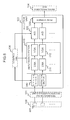
- signal amplification is performed. Therefore, as shown in Fig. 3 , the reception unit 103 includes an analog circuit (amplification section) 310 that performs analog amplification (or attenuation) of the received echo, an analog-to-digital conversion circuit (analog-to-digital conversion section; A/D conversion section) 320 that converts the echo after analog amplification into digital data, and a beam former 330.
- the beam former 330 generates a reception beam by adding the digital data of each channel 801 after applying the delay time corresponding to the focus point thereto.
- the amplification section 310 and the A/D conversion section 320 are provided for each channel of the ultrasonic probe 108.
- amplifiers such as an LNA 311 and a VGA 312 are provided.
- the amplification factor of each amplifier provided in the amplification section 310 is controlled by a control signal from the control unit 106.
- the amplification factor is changed to a amplification factor designated by the control signal.
- the signal processing unit 104 performs amplification processing, filtering processing, and signal arithmetic processing on the signal (reception beam) received from the reception unit 103. Therefore, as shown in Fig. 2B , the signal processing unit 104 includes a memory 401, an arithmetic processing section 402 that performs arithmetic processing on a signal, and a filtering section 403 that performs filtering processing.
- the amplification processing is performed according to time gain compensation (TGC), a amplification factor, or the like set by the user through the user interface 121. If necessary, the reception beam is temporarily stored in the memory 401. An output from the signal processing unit 104 is transmitted to the image processing unit 107.
- TGC time gain compensation
- the image processing unit 107 constructs image data and time-series data using a nonlinear component that is output from the signal processing unit 104.
- the constructed image data and time-series data are output to the display unit 122 so as to be displayed thereon.
- the control unit 106 controls the operations of the transmission unit 102, the reception processing unit 105, and the image processing unit 107. In the present embodiment, the control unit 106 controls the operations by transmitting a control signal to each of the units, thereby realizing the THI. Details of the control performed by the control unit 106 of the present embodiment will be described later.
- the control unit 106 includes a CPU, a memory, and a storage device, and each of the functions described above is realized when the CPU loads a program stored in the storage device to the memory and executes it.
- ultrasonic imaging apparatus 100 excluding the ultrasonic probe 108 can also be mounted in a separate housing from the ultrasonic probe 108 as a main unit. Some of the component can be disposed in the ultrasonic probe 108.
- the transmission of an ultrasonic beam to the same imaging part is performed multiple times, the echo (reception signal) of each transmission is stored, and image data of a predetermined imaging region is generated by the stored reception signals.
- the number of transmissions is 2 times will be described as an example.
- the amplitude of a transmission signal 511 is set to a predetermined amplitude (set amplitude) p, and the ultrasonic beam is transmitted.
- the amplitude of the transmission signal 521 is modulated to 1/k (k is a real number satisfying k > 1) times the set amplitude p, and the ultrasonic beam is transmitted.
- the transmission in which the amplitude of the transmission signal is the set amplitude p (first transmission) is called non-modulated transmission
- the transmission in which the amplitude of the transmission signal is set by modulating the set amplitude (second transmission) is called modulated transmission.
- 1/k is the amplitude ratio of the ultrasonic beam generated from a transmission signal 521 at the time of modulated transmission to the ultrasonic beam generated from the transmission signal 511 at the time of non-modulated transmission.
- k is also referred to as a modulation coefficient.
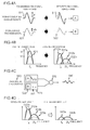
- Reception signals (echoes) obtained by the respective transmissions are assumed to be a non-modulated reception signal 512 and a modulated reception signal 522.
- the center frequency of the fundamental wave component of the transmission signal is set to f 0 .
- the main center frequency of the nonlinear component is 2f 0 .
- the nonlinear component is generated in proportion to the square of the sound pressure level (amplitude) of the echo. Therefore, as shown in Fig. 4B , the amplitude of a nonlinear component 522b of the modulated reception signal 522 is 1/k 2 of the amplitude p of a nonlinear component 512b of the non-modulated reception signal 512, and the generation rate of the nonlinear component from the modulated reception signal 522 is smaller than the generation rate from the non-modulated reception signal 512. From the law of energy conservation, the energy of fundamental wave band components 512a and 522a that are original signal components decreases according to the generated nonlinear components 522b and 512b.
- the arithmetic processing section 402 performs multiplication processing for multiplying a modulation coefficient k so that the energy of the modulated reception signal 522 matches the energy of the non-modulated reception signal 512, subtracts the result from the non-modulated reception signal 512, and extracts an acoustic distortion component (THI signal) configured to mainly include a nonlinear component.
- TTI signal acoustic distortion component
- an acoustic distortion component (THI signal) 540 configured to mainly include a nonlinear component is extracted by performing arithmetic processing 550 shown in Fig. 4C .
- arithmetic processing 550 multiplication processing 551 for multiplying the modulated reception signal 522 by k is performed to generate a signal 523 having numerically the same energy as the non-modulated reception signal 512.
- subtraction processing 552 for subtracting the generated signal 523 from the non-modulated reception signal 512 is performed.
- a fundamental wave band component 523a and a nonlinear component 523b of the signal 523 are different from the fundamental wave band component 512a and the nonlinear component 512b of the non-modulated reception signal 512. Both the differences in the two bands are caused by nonlinear propagation.
- the subtraction processing 552 not only a difference between nonlinear components 540b but also a difference between fundamental wave band components 540a is obtained as the acoustic distortion component (THI signal) 540.
- This acoustic distortion component (THI signal) 540 is a component proportional to the square of the sound pressure amplitude p of the transmission acoustic wave, and constructs an image from the THI signal to realize the THI.
- the multiplication processing 551 may be set to multiply the non-modulated reception signal 512 by 1/k.
- the arithmetic processing 550 is performed on digital data obtained by digital conversion after analog amplification in the analog amplifier.
- the dynamic range (linear amplification range) of the analog amplifier in which the linearity of the output signal to the input signal is maintained is limited.
- the amount of amplification or the phase characteristic of the output signal is deformed. This distorts the waveform of the output signal, or causes saturation (clip).
- the amplitude ratio between the non-modulated reception signal 512 and the modulated reception signal 522 after passing through the analog amplifier is also different from the amplitude ratio (1/k) before passing through the analog amplifier. Since the arithmetic processing 550 is performed on the assumption that the non-modulated reception signal 512 is an amplitude ratio (1/k) at the time of transmission, it is not possible to correctly perform the calculation if the amplitude ratio is different from the assumption.
- the amplification factor of the amplification section 310 is G
- the amplitudes of the respective output signals are p*G and p*G/k.
- the signal waveform of the output from the amplification section 310 is distorted or clipped.
- the amplitude of the output signal from the amplification section 310 of the non-modulated reception signal 512 becomes smaller than the assumption. That is, the amplitude of the non-modulated reception signal 512 after passing through the amplification section 310 is smaller than p*G. Therefore, the amplitude ratio of two signals obtained after passing through the amplification section 310 is not 1/k.
- control unit 106 controls the reception processing unit 105 such that the influence of electrical distortion on the signal waveform of the reception signal (echo) due to analog amplification is approximately the same between the reception signal obtained from the echo of the non-modulated transmission and the reception signal obtained from the echo of the modulated transmission. In the present embodiment, this is realized by controlling the amplification factor of the amplification section 310.
- control unit 106 of the present embodiment controls the amplification factor of the amplification section 310 with respect to the reception signal obtained from the echo of the modulated transmission such that the waveform distortion of the reception signal obtained from the echo of the modulated transmission after the amplification in the amplification section 310 is approximately the same as the waveform distortion of the reception signal obtained from the echo of the non-modulated transmission after the amplification in the amplification section 310.
- the amplification factor of the modulated reception signal 522 is controlled such that the waveform distortion of the modulated reception signal 522 after the amplification in the amplification section 310 is approximately the same as the waveform distortion of the non-modulated reception signal 512 after the amplification in the amplification section 310.
- the amplification factor at which the waveform distortions are approximately the same is k times the set amplification factor G, as described above.
- the set amplification factor G is an amplification factor set in the amplification section 310 in advance, and is an amplification factor of the amplification section 310 with respect to the echo of the non-modulated transmission.
- This control is performed by transmitting a control signal from the control unit 106 to the amplification section 310.
- the amplification section 310 of the present embodiment amplifies the reception signal with the set amplification factor.
- the reception signal is amplified with a amplification factor according to the control signal.
- the arithmetic processing section 402 of the signal processing unit 104 of the present embodiment only the subtraction processing 552 is performed to extract a nonlinear component. This is because the multiplication processing 551 of the arithmetic processing 550 described above is the same as processing for setting the amplification factor of the modulated reception signal 522 to k times the set amplification factor G.
- the amplification factor of the VGA 312 is changed.
- the amplification factor (set amplification factor) of the VGA 312 with respect to the non-modulated reception signal 512 is Gv
- the amplification factor of the VGA 312 with respect to the modulated reception signal 522 is set to k*Gv times.
- the modulated reception signal 522 after passing through the VGA 312 becomes a signal waveform having the features of the same electrical distortion or clipping as the non-modulated reception signal 512.
- the subtraction processing 552 is performed on these signals, electrical distortion components in the VGA 312 are canceled, and only the acoustic distortion component (THI signal) 540 generated during the propagation of the acoustic wave remains.
- the change of the amplification factor in the amplification section 310 is not limited to the VGA 312.
- the change of the amplification factor may also be performed in the LNA 311 connected before the VGA 312.
- the change of the amplification factor may be performed in any of the amplifiers.
- the number of transmissions in the amplitude modulation method is not limited to 2 times.
- the number of transmissions in the amplitude modulation method may be N times (N is an integer of 3 or more).
- N is an integer of 3 or more.
- the amplitude (set amplitude) of the non-modulated transmission is p
- the modulation coefficient of the modulated transmission that is the n-th (n is an integer of 2 or more and N or less) transmission is k n (k n > 1)
- the amplitude of the transmission signal is set to p/k n .
- the non-modulated transmission is not limited to the first transmission.
- the arithmetic processing 550 in order to make equal the sum of the energy of the non-modulated reception signal and the energy of the modulated reception signal, the difference between the energy of the non-modulated reception signal and the energy of the modulated reception signal is calculated. Therefore, when the number of transmissions is N times, in order to make equal the sum of the energy of each modulated reception signal, processing of multiplying each modulated reception signal by the modulation coefficient k n is performed, and then the average value is calculated.
- the multiplication processing 551 of multiplying the modulated reception signal by the modulation coefficient k n is calculated by the following equation (1).
- the result of the multiplication processing 551 is set to SM.
- the average value calculation process of the multiplication process result is calculated by the following equation (2).
- the result of the average value calculation process is set to SA.
- This SS is the acoustic distortion component (THI signal) 540 generated during the propagation of the acoustic wave.
- a nonlinear component is extracted by calculating the average value of digital data obtained from the echo of the modulated transmission after amplification corresponding to the modulation coefficient k n and subtracting the obtained value from the digital data obtained from the echo of the non-modulated transmission.
- the modulation coefficient k n is the inverse of the ratio of the amplitude of the ultrasonic beam of the modulated transmission to the set amplitude.
- the modulation coefficient multiplication process may be arithmetic processing for multiplying each reception signal by -k n .
- equation (3) becomes arithmetic processing for adding S 1 and SA.
- the control unit 106 transmits a control signal to the amplification section 310 for each reception of the echo in order to control the amplification factor. Specifically, when amplifying the modulated reception signal having the modulation coefficient of k n , a control signal is transmitted such that the amplification factor of the amplification section 310 becomes k n *G. G is the set amplification factor of the amplification section 310.
- the signal processing unit 104 performs only the average value calculation processing of the above equation (2) and the subtraction processing of the above equation (3).
- the number of non-modulated transmissions and the modulation coefficient of the amplitude at the time of each modulated transmission are stored in a storage device provided in the control unit 106 or the like in advance. Based on this information, the control unit 106 generates the above-described control signal, and transmits the control signal to the amplification section 310.
- one non-modulated transmission for transmitting an ultrasonic beam to the predetermined position of the imaging target with the set amplitude that is set in advance and one or more modulated transmissions for transmitting an ultrasonic beam with an amplitude obtained by modulating the set amplitude are performed to obtain each echo, the influence of electrical distortion due to analog amplification is approximately the same between the echo of the non-modulated transmission and the echo of the modulated transmission, and a nonlinear component is extracted from the obtained result.
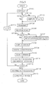
- Fig. 5 is a process flow of the THI of the present embodiment.
- the number of transmissions for creating the image data of an imaging region set in advance is N times
- the amplitude of the first transmission signal is the set amplitude p
- the modulation coefficient of the n-th transmission (second or subsequent transmission) is k n . That is, the amplitude of the transmission signal of the n-th transmission (second or subsequent transmission) is set to p/k n .
- the amplification factor of the amplification section 310 is assumed to be the set amplification factor G.
- the set amplitude p, the coefficient k n , and the set amplification factor G are determined in advance and are stored in the storage device.
- control unit 106 initializes each unit (step S1001).
- n that is used as a counter is set to 1
- the amplitude of the transmission signal is set to the set amplitude p
- the amplification factor of the amplification section 310 is set to the set amplification factor G.
- the control unit 106 determines whether or not the counter n is 1 (step S1102). If the counter n is not 1, the control unit 106 transmits a control signal to the transmission unit 102 so that the amplitude of the transmission signal is modulated to a modulation coefficient p/k n (step S1103), and the transmission unit 102 transmits an ultrasonic beam (step S1104). On the other hand, if n is 1 in step S1102, the process proceeds to step S1104 to transmit the ultrasonic beam.
- step S1106 the control unit 106 determines whether or not the counter n is 1 (step S1106). If the counter n is not 1, the control unit 106 transmits a control signal to the amplification section 310 in order to set the amplification factor to k n *G (step S1107), and the amplification section 310 amplifies a reception signal generated for each channel from the received echo (step S1108). On the other hand, if n is 1 in step S1106, the process proceeds to step S1108 in which the amplification section 310 amplifies the reception signal for each channel. The amplification factor at this time is the set amplification factor G.
- control unit 106 causes the A/D conversion section 320 to convert the reception signal for each channel after the amplification into a digital signal (step S1109), and causes the beam former 330 to perform beam forming of the digital signal for each channel to generate a reception beam (step S1110).
- the control unit 106 causes the filtering section 403 to perform filtering processing, and the result is stored in the memory 401 as digital data (step S1111).
- the control unit 106 repeats the process of steps S1102 to S1111 for all reception signals. That is, the process of steps S1102 to S1111 is repeated until n becomes N (steps S1112 and S1113).
- control unit 106 transmits a control signal to the signal processing unit 104 so that the arithmetic processing section 402 performs arithmetic processing using the digital data stored in the memory 401 (step S1114), thereby extracting a THI signal. Then, the control unit 106 causes the image processing unit 107 to construct an image using the extracted THI signal (step S1115).
- the amplitude k n of each transmission signal may differ depending on each transmission, and may be the same for the second and subsequent transmissions.
- the non-modulated transmission may not be the first transmission.
- the set amplitude is p and the set amplification factor of the amplification section 310 is G.
- a reception signal generated from the echo of the first transmission, a reception signal generated from the echo of the second transmission, and a reception signal generated from the echo of the third transmission are referred to as a first reception signal, a second reception signal, and a third reception signal, respectively.
- control unit 106 sets the amplification factor of the amplification section 310 to the set amplification factor G at the time of amplification of the first reception signal.
- a control signal is output to the amplification section 310 so that the amplification factor is set to 2*G.
- the A/D conversion section 320 digitally converts each reception signal after the amplification to obtain digital data.
- the beam former 330 performs beam forming of the obtained digital data, and then stores the result in the memory 401 as digital data.
- the arithmetic processing section 402 performs predetermined arithmetic processing using all pieces of the digital data in the memory 401.
- the second and third reception signals are amplified to twice the first reception signal. Accordingly, the sum of the energy of the second reception signal and the energy of the third reception signal is twice the energy of the first reception signal.
- the above-described average value calculation processing is performed on the digital data obtained from the second reception signal and the digital data obtained from the third reception signal. Then, the result is subtracted from the digital data obtained from the first reception signal.
- This arithmetic processing may be arithmetic processing for multiplying the addition result of the digital data obtained from the second reception signal and the digital data obtained from the third reception signal by -1/2 and adding the multiplication result and the digital data obtained from the first reception signal.
- control is performed so as to increase the amplification factor at the time of amplification of the modulated reception signal.
- the amplification factor may be reduced at the time of amplification of the non-modulated reception signal. That is, the amplification factor of the modulated reception signal may be set to the set amplification factor G as it is, and the amplification factor of the non-modulated reception signal may be set to G/k.
- the control unit 106 controls the amplification factor of the amplification section 310 with respect to the non-modulated reception signal so as to become 1/k times the set amplification factor G.
- an amplification factor with respect to the modulated reception signal is assumed to be the set amplification factor G. That is, when receiving the echo of the non-modulated transmission, the control unit 106 transmits a control signal instructing a change of the amplification factor to the amplification section 310. In addition, when receiving the echo of the modulated transmission, no control signal may be transmitted.
- the arithmetic processing section 402 performs subtraction processing after making equal the sum of the energy of the digital data obtained from the non-modulated reception signal and the energy of the digital data obtained from the modulated reception signal.
- one amplification section 310 is provided for each channel, and the amplification factor is changed when amplifying the modulated reception signal.
- the configuration of the amplification section 310 is not limited thereto.
- an amplification section to be used for amplification of the non-modulated reception signal and an amplification section to be used for amplification of the modulated reception signal may be separately provided, and an amplification section to be used may be controlled by a switch or the like.
- only an amplifier for changing the amplification factor may be provided for each transmission.
- a nonlinear component is extracted by making the influence on the echo due to analog amplification approximately the same between the echo of the non-modulated transmission and the echo of the modulated transmission.
- the influence on the echo due to analog amplification is made to be approximately the same by controlling the amplification factor of the amplification section 310.
- the amplification factor of the amplification section 310 with respect to the echo of the modulated transmission is changed.
- the amplification factor with respect to the echo of the modulated transmission is set such that the waveform distortion after the amplification in the amplification section 310 is approximately the same as the waveform distortion after the amplification of the non-modulated transmission. Specifically, when the amplitude of the ultrasonic beam at the time of modulated transmission is 1/k times the amplitude of the ultrasonic beam at the time of non-modulated transmission, the amplification factor with respect to the echo of the modulated transmission is set to k times the amplification factor with respect to the echo of the non-modulated transmission.
- the waveform distortion of the non-modulated reception signal after amplification becomes approximately the same as the waveform distortion of the modulated reception signal after amplification
- the amplitude ratio of both the non-modulated reception signal and the modulated reception signal after analog amplification is the same as that assumed. Based on this, it is possible to correctly perform subsequent arithmetic processing. Therefore, since it is possible to extract a nonlinear component with high accuracy, the obtained image quality is also improved.
- the ultrasonic imaging apparatus 100 it is necessary to simultaneously process the echoes of various strengths. This is because an imaging target that causes a strong echo and an imaging target that does not cause a strong echo may be simultaneously imaged and the strength of the echo changes depending on the position and angle of the imaging target with respect to the ultrasonic probe 108. For this reason, a high echo is received in some channels of the ultrasonic probe 108, while a low echo is received in other channels. In addition, whenever an imaging region changes, the strength of an echo received by the ultrasonic probe 108 changes in various ways.
- the ultrasonic imaging apparatus 100 may receive, in the analog circuit (amplifier). Therefore, it is difficult to make the reception signals of both the high echo and the low echo fall within the dynamic range of the amplifier in order to amplify both the signals with high accuracy.
- amplification of the signal amplitude in the amplifier is indispensable. Therefore, it is desirable to set the dynamic range of the amplifier to a range corresponding to the low echo signal. For this reason, in particular, the reception signal that becomes a high echo is easy to reach the outside of the dynamic range of the amplifier.
- the influence (electrical distortion or clipping) of the received waveform after amplification can be made to be the same. Therefore, it is possible to realize the high-accuracy nonlinear component extraction described above.
- the influence on the echo due to analog amplification is made to be approximately the same among all echoes by controlling the amplification factor of the amplification section.
- the amplification factor is changed between the modulated reception signal and the non-modulated reception signal.
- the amplification factor is changed only when the amplitude of the non-modulated reception signal deviates from the linear amplification range of the amplification section.
- the configuration of the ultrasonic imaging apparatus 100 of the present embodiment is basically the same as that of the first embodiment. In the present embodiment, however, as described above, it is determined whether or not the amplitude of the non-modulated reception signal deviates from the linear amplification range of the amplification section 310. Therefore, the configuration of the reception unit 103 is different. In addition, the processes of the signal processing unit 104 and the control unit 106 are also different. The following explanation will be focused on a configuration different from the first embodiment.
- the reception unit 103 of the present embodiment further includes a detection section 340 that is connected before the amplification section 310 and detects the amplitude of the reception signal (non-modulated reception signal) obtained from the echo of the non-modulated transmission.
- the detection section 340 receives a non-modulated reception signal and detects the maximum amplitude, and notifies the control unit 106 of the result.
- the control unit 106 of the present embodiment sends an instruction to detect the amplitude of the reception signal to the detection section 340, and determines whether or not to change the amplification factor of the amplification section 310 when amplifying the modulated reception signal according to the detection result. Then, only when it is determined that the amplification factor of the amplification section 310 when amplifying the modulated reception signal is changed, a control signal is transmitted to the amplification section 310. Otherwise, no control signal is transmitted to the amplification section 310.
- the amplification factor of the amplification section 310 when amplifying the modulated reception signal is changed.
- the determination regarding whether or not to change the amplification factor of the amplification section 310 is performed according to whether or not the maximum amplitude detected by the detection section 340 exceeds a predetermined threshold value.
- the maximum amplitude detected by the detection section 340 exceeds the predetermined threshold value, it is determined that the amplification factor of the amplification section 310 is changed.
- the threshold value is calculated in advance according to the connection order of each amplifier circuit connected within the amplification section 310 and the linear amplification range of each amplifier circuit, and is stored in the storage device of the control unit 106.
- the amplification section 310 changes the amplification factor only when a control signal is received from the control unit 106. Also in the present embodiment, as in the first embodiment, when amplifying the modulated reception signal having the modulation coefficient of k n , a control signal is transmitted such that the amplification factor of the amplification section 310 becomes k n *G. G is the set amplification factor of the amplification section 310.
- the control unit 106 of the present embodiment transmits a control signal to the signal processing unit 104.
- the arithmetic processing section 402 of the signal processing unit 104 performs the multiplication processing 551 of the above equation (1), the average value calculation processing of the above equation (2), and the subtraction processing 552 of the above equation (3), as the arithmetic processing 550.
- the multiplication processing 551 is not performed. This is because processing equivalent to the multiplication processing 551 is performed in the preceding amplification section 310.
- the detection section 340 is disposed in the first stage of the reception unit 103 in Fig. 6
- the arrangement position is not limited thereto.
- the detection section 340 may be disposed inside the amplification section 310, or may be disposed in the later stage.
- the control unit 106 determines the above threshold value in advance according to the arrangement position of the detection section 340 and the data of the linear amplification range of each amplifier circuit, and stores the threshold value in the storage device or the like.
- an amplifier circuit itself such as the LNA 311 or the VGA 312, may be configured to function as the detection section 340.
- the amplification factor of the modulated reception signal is determined according to the amplitude of the non-modulated reception signal. For this reason, non-modulated transmission is set as the first transmission.
- the flow of the process of the THI according to the amplitude modulation method of the present embodiment will be described.
- the amplification factor of the amplification section 310 when performing analog amplification of the modulated reception signal is changed.
- Fig. 7 is a process flow of the THI of the present embodiment.
- the number of transmissions for creating the image data of an imaging region set in advance is N times
- the amplitude of the first transmission signal is the set amplitude p
- the modulation coefficient of the n-th transmission (second or subsequent transmission) is k n . That is, the amplitude of the transmission signal of the n-th transmission (second or subsequent transmission) is set to p/k n .
- the amplification factor of the amplification section 310 is set to the set amplification factor G.
- the set amplitude p, the coefficient k n , and the set amplification factor G are determined in advance and are stored in the storage device.
- control unit 106 initializes each unit (step S1201).
- n that is used as a counter is set to 1
- the amplitude of the transmission signal is set to the set amplitude p
- the amplification factor of the VGA 312 is set to the set amplification factor G.
- a flag to be described later is also initialized.
- the control unit 106 determines whether or not the counter n is 1 (step S1202). If the counter n is not 1, the control unit 106 transmits a control signal to the transmission unit 102 so that the amplitude of the transmission signal is modulated to a modulation coefficient p/k n (step S1203), and the transmission unit 102 transmits an ultrasonic beam (step S1204) . On the other hand, if n is 1 in step S1202, the process proceeds to step S1204 directly to transmit the ultrasonic beam.
- control unit 106 determines whether or not the counter n is 1 (step S1206).
- the control unit 106 transmits a control signal to the detection section 340 so that the detection section 340 detects an amplitude, and receives the detection result (step S1207). Then, it is determined whether or not the received detection result is within the linear amplification range of the amplification section 310 by comparing the received detection result with the threshold value (step S1208). When the received detection result exceeds the threshold value, a flag is set (step S1209), and the process proceeds to the amplification processing of the amplification section 310 (step S1212). This flag is a flag that means increasing the amplification factor of the reception signal according to the modulated transmission. On the other hand, when the received detection result does not exceed the threshold value, no flag is set, and the process proceeds to the amplification processing (step S1212) directly.
- the control unit 106 determines whether or not a flag is set (step S1210). When a flag is set, the control unit 106 transmits a control signal to the amplification section 310 so that the amplification factor becomes k n *G (step S1211), and the amplification section 310 performs amplification processing (step S1212). On the other hand, when no flag is set, a control signal to change the amplification factor is not transmitted, and the amplification processing is performed with the amplification factor G (step S1212).
- control unit 106 causes the A/D conversion section 320 to convert the reception signal for each channel after the amplification into a digital signal (step S1213), and causes the beam former 330 to perform beam forming of the digital signal for each channel to generate a reception beam (step S1214).
- the control unit 106 causes the filtering section 403 to perform filtering processing, and the result is stored in the memory 401 as digital data (step S1215).
- the control unit 106 repeats the process of steps S1202 to S1214 for all reception signals. That is, the process of steps S1202 to S1214 is repeated until n becomes N (steps S1216 and S1217).
- the control unit 106 causes the arithmetic processing section 402 to perform arithmetic processing using the digital data stored in the memory 401 (step S1218), thereby extracting a THI signal.
- the arithmetic processing 550 described in the first embodiment is performed.
- the control unit 106 causes the image processing unit 107 to construct an image using the extracted THI signal (step S1219).
- the modulation coefficient k n to determine the amplitude of the transmission signal of each modulated transmission may differ depending on each transmission, and may be the same for all transmissions.
- a case in which the number of transmissions is 2 times and the modulation coefficient k at the time of modulated transmission is 2 will be specifically described as an example.
- the set amplitude is p and the set amplification factor of the amplification section 310 is G.
- a reception signal generated from the echo of the first transmission and a reception signal generated from the echo of the second transmission are referred to as a first reception signal and a second reception signal, respectively.
- the control unit 106 causes the detection section 340 to detect the amplitude, and determines whether or not the amplitude is equal to or less than a predetermined threshold value.
- a flag that means changing the amplification factor when receiving the second reception signal is set.
- no flag is set.
- the control unit 106 When the second reception signal is received, the control unit 106 refers to a flag. If the flag is set, the control unit 106 transmits a control signal, which instructs to set the amplification factor to 2*G, to the amplification section 310, so that the amplification section 310 performs amplification processing. Then, the arithmetic processing section 402 extracts a THI signal by subtracting the above result from the digital data generated from the first reception signal.
- the arithmetic processing section 402 extracts a THI signal by doubling the obtained digital data and subtracting the result from the digital data generated from the first reception signal.
- the arithmetic processing section 402 may be configured to multiply the digital data obtained from the second and subsequent reception signals by -1/k n and add the result and the first reception signal.
- digital data obtained from the second and subsequent reception signals may be multiplied by -1, and the result and the first reception signal may be added.
- the amplification factor of the non-modulated reception signal may be changed. That is, when the amplitude of the non-modulated reception signal is greater than the predetermined threshold value, the amplification factor of the non-modulated reception signal is set to G/k. In this case, the amplification factor of the modulated reception signal is assumed to be the set amplification factor G.
- an amplification section having an amplification factor of k and an amplification section having an amplification factor of k*G may be separately provided so that switching between amplification sections to be used is performed according to the designated amplification factor.
- the detection section 340 that detects the amplitude of the echo of the non-modulated transmission is further provided. Then, when the amplitude detected by the detection section 340 is equal to or greater than the predetermined threshold value, the control unit 106 controls the amplification factor of the amplification section 310 in the same manner as in the first embodiment. For example, only when the non-modulated reception signal 512 exceeds the linear amplification range of the amplification section 310, the amplification factor of the amplification section 310 of the modulated reception signal 522 is changed. Therefore, waveform distortions after analog amplification of the respective reception signals that form one scanning line can be efficiently made to be approximately the same compared with the first embodiment. Therefore, the same effect as in the first embodiment can be efficiently obtained.
- the present invention when the amplitude of the non-modulated reception signal exceeds the linear amplification range of the amplification section 310, the amplification factor of the amplification section 310 is controlled. In the present embodiment, however, the amplitude of the reception signal amplified by changing the amplification factor is returned to the original amplitude before the input to the signal processing unit 104 thereafter. Then, the signal processing unit 104 performs the arithmetic processing 550 regardless of the magnitude of the amplitude of the non-modulated transmission.
- the configuration of the ultrasonic imaging apparatus 100 of the present embodiment is basically the same as that of the second embodiment.
- the modulated reception signal is amplified by changing the amplification factor and is then returned to have the original amplitude.
- the reception unit 103 includes a digital gain 350, which digitally amplifies (attenuates) the reception signal after digital conversion (digital data), after the A/D conversion section 320.
- the digital gain 350 is a circuit that linearly amplifies a signal of any amplitude with a desired amplification factor. For example, a signal that has caused electrical waveform distortion in the amplification section 310 maintains the distorted waveform even after the passage of the digital gain 350.
- the modulated reception signal after amplification in the amplification section 310 is returned to have the original amplitude according to the control signal from the control unit 106.
- the control unit 106 transmits a control signal instructing the change of the amplification factor not only to the amplification section 310 but also to the digital gain 350.
- the control unit 106 controls the digital gain 350 to multiply the digital data obtained from the echo by 1/k.
- amplified data obtained by increasing the amplification factor k times in the amplification section 310 is amplified to 1/k times in the digital gain 350, thereby being returned to the original data.
- arithmetic processing in the subsequent arithmetic processing section 402 may be the arithmetic processing 550 described in the first embodiment, as in the related art. Therefore, the control unit 106 of the present embodiment transmits no control signal to the subsequent signal processing unit 104 regardless of the setting of the flag.
- the number of transmissions N is set to 2
- the first transmission is set to non-modulated transmission
- the second transmission is set to modulated transmission
- the modulation coefficient k 2 of the modulated transmission is set to 2.
- ratio of the energy of the waves of two transmission signals is 4:1.
- the second reception signal amplified with the doubled amplification factor by the amplification section 310 is amplified to 1/2 times by the subsequent digital gain 350. Accordingly, only the amplitude of the second reception signal is reduced to 1/2 times while maintaining the distorted waveform. Therefore, the energy ratio between the two signals is 4: 1 that is the same as at the time of transmission.
- subsequent arithmetic processing in the arithmetic processing section 402 is the multiplication processing 551 and the subtraction processing 552, that is, S 1 - (k 2 * S 2 ), that is, S 1 - 2 * S 2 , as in the related art.
- the control unit 106 doubles the amplification factor of the amplification section 310 with respect to the second and third reception signals.
- the energy of each reception signal after amplification is numerically the same.
- the second and third reception signals amplified with the doubled amplification factor are amplified to 1/2 times by the subsequent digital gain 350.
- the energy ratio of the respective reception signals becomes the same as at the time of transmission.
- subsequent arithmetic processing in the arithmetic processing section 402 is the multiplication processing 551, average value calculation processing, and the subtraction processing 552, that is, S 1 - (k 2 * S 2 + k 3 * S 3 )/(3 -1), that is, S 1 - (S 2 + S 3 ), as in the related art.
- the amplification factor of the non-modulated reception signal may be set to 1/k times, and may be set to k times in the digital gain 350. In this case, for the modulated reception signal, the amplification factor of the amplification section 310 is not changed, and amplification is not performed in the digital gain 350.
- the digital gain 350 is connected immediately after the A/D conversion section 320. Since the digital gain 350 is intended to change the amplitude of the reception signal after conversion into digital data, the digital gain 350 may be disposed anywhere in the reception unit 103 as long as the position is after the A/D conversion section 320. For example, the digital gain 350 may be disposed after the beam former 330.
- control unit 106 transmits a control signal to the digital gain 350 during echo reception for all modulated transmissions.
- non-modulated transmission may not be the first transmission.
- the digital gain 350 that digitally amplifies the digital data is further provided.
- the control unit 106 controls the digital gain 350 to amplify the digital data obtained from the echo to 1/k times.
- the amplification factor at the time of analog amplification of the reception signal obtained from the echo of the ultrasonic beam is changed according to the amplitude of the transmitted ultrasonic beam.
- the change is performed so that the influence on the echo due to analog amplification is approximately the same between the respective echoes.
- the amplification factor of the amplification section 310 is changed, returning to the original amplitude is performed in the digital gain 350.
- the amplitude ratio of both the non-modulated reception signal and the modulated reception signal after analog amplification is the same as that assumed. Based on this, it is possible to correctly perform subsequent arithmetic processing.
- the amplitude ratio of both signals before arithmetic processing is 1/k as in the related art.
- the conventional arithmetic processing section can be used as it is for arithmetic processing in the signal processing unit 104. Therefore, according to the present embodiment, it is possible to obtain the same effect as in the first or second embodiment without changing the signal processing unit 104.
- the influence on the echo due to analog amplification is made to be the same among reception signals by controlling the amplification factor of the amplification section.
- the arithmetic processing is performed after the beam forming of data for each channel in each of the embodiments described above, the arithmetic processing is performed before the beam forming for the data of each channel in the present embodiment.
- the ultrasonic imaging apparatus 100 of the present embodiment has basically the same configuration as in the first embodiment. However, the configuration of the reception unit 103 and the signal processing unit 104, the processing of the beam former 330, and the processing of the control unit 106 that controls these are different. Hereinafter, the present embodiment will be described focusing on the different configuration from the first embodiment.
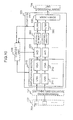
- the reception unit 103 of the present embodiment further includes a channel memory 360, in which a reception signal (digital data) after conversion in the A/D conversion section 320 is stored for each channel, and a calculator 370 that extracts a nonlinear component for each channel by performing arithmetic processing on the digital data stored in the channel memory 360.
- a channel memory 360 in which a reception signal (digital data) after conversion in the A/D conversion section 320 is stored for each channel
- a calculator 370 that extracts a nonlinear component for each channel by performing arithmetic processing on the digital data stored in the channel memory 360.
- the channel memory 360 is connected after the A/D conversion section 320, and digital data converted from each reception signal in N receptions is stored for each channel.
- the calculator 370 is connected after the channel memory 360, and performs arithmetic processing for each channel using the digital data of each channel memory 360 after N receptions.
- the average value calculation processing and the above-described subtraction processing 552 described above are performed.
- the beam former 330 of the present embodiment performs beam forming of the data after arithmetic processing. That is, beam forming of the extracted nonlinear component for each channel is performed. Then, the image processing unit 107 of the present embodiment constructs an image using the beam forming result.
- the signal processing unit 104 of the present embodiment does not need to include the arithmetic processing section 402 since the calculator 370 performs arithmetic processing.
- the amplification factor of the non-modulated reception signal may be changed.
- an amplifier may be provided for each amplification factor.
- the detection section 340 may be provided before the amplification section 310, and the amplification factor of the modulated transmission and reception signals may be changed only when the amplitude of the non-modulated reception signal exceeds the linear amplification range of the amplification section 310.
- control unit 106 when changing the amplification factor, the control unit 106 also transmits a control signal to the calculator 370.
- the calculator 370 performs not only the average value calculation processing and the subtraction processing 552 described above but also the multiplication processing 551 on the data for each channel.
- a signal amplified by changing the amplification factor may be processed to have the original amplitude before arithmetic processing.
- the same arithmetic processing as in the related art is performed for any signal.
- the channel memory 360 in which the digital data after conversion in the digital conversion section 320 is stored for each channel
- the calculator 370 that extracts the nonlinear component for each channel by performing arithmetic processing on the digital data stored in the channel memory 360
- the beam former 330 that performs beam forming of the extracted nonlinear component for each channel.
- the amplification factor at the time of analog amplification of the reception signal obtained from the echo of the ultrasonic beam is changed according to the amplitude of the transmitted ultrasonic beam. The change is performed so that the influence on the echo due to analog amplification is approximately the same between the respective echoes. Then, a nonlinear component is extracted for each channel.
- the waveform distortion of the non-modulated reception signal after amplification becomes approximately the same as the waveform distortion of the modulated reception signal after amplification
- the amplitude ratio of both the non-modulated reception signal and the modulated reception signal after analog amplification is the same as that assumed. Based on this, it is possible to correctly perform subsequent arithmetic processing.
- the digital data before beam forming is already a nonlinear component, it is sufficient to perform the beam forming processing for creating the image data of the imaging region set in advance only once. Therefore, according to the present embodiment, it is possible to extract a nonlinear component with high accuracy, in the same manner as in the first embodiment, by one beam forming processing without performing beam forming processing for each transmission. As a result, the obtained image quality is also improved.
- the influence of electrical distortion of the signal waveform received in the amplification section 310 formed by an analog amplifier is made to be approximately the same for all reception signals by using a filter.
- the present embodiment is based on the assumption that the input and output characteristics of the amplification section 310 are known.
- the ultrasonic imaging apparatus 100 of the present embodiment has basically the same configuration as in the first embodiment. However, the configuration of the reception unit 103 is different, and the processing of the control unit 106 that controls these is different. Hereinafter, the present embodiment will be described focusing on the different configuration from the first embodiment.
- the reception unit 103 of the present embodiment further includes a channel memory 360, in which digital data converted by the A/D conversion section 320 is stored for each channel, and a filter 380 that performs filtering processing on the digital data.
- the amplification section 310 of the present embodiment amplifies a non-modulated reception signal and a modulated reception signal with an amplification factor (set amplification factor) G set in advance.
- the amplification factor is not changed according to the modulated reception signal and the non-modulated reception signal.
- the channel memory 360 is connected after the A/D conversion section 320, and digital data converted from each of reception signals that are received N times is stored for each channel.
- the filter 380 of the present embodiment has approximately the same transfer function as the input and output characteristics of the amplification section 310. That is, the waveform after passing through the filter 380 shows approximately the same electrical distortion as after passing through the amplification section 310. Therefore, the filtering processing of the filter 380 of the present embodiment is processing for giving the same waveform distortion as electrical distortion that the non-modulated reception signal receives to the modulated reception signal.
- the filter 380 of the present embodiment reads data from the channel memory 360 after all transmissions are completed, and performs this filtering processing on the digital data obtained from the modulated reception signal. The filtering processing of the filter 380 is performed according to the control signal from the control unit 106.
- the beam former 330 of the present embodiment performs beam forming processing on the digital data for each channel after the filtering processing. Then, the signal processing unit 104 of the present embodiment performs the same arithmetic processing as in the first embodiment for the reception beam after the beam forming. That is, the average value calculation processing and the subtraction processing 552 are performed to extract a nonlinear component. Then, the image processing unit 107 of the present embodiment constructs an image from the nonlinear component extracted by the signal processing unit 104.
- the filter 380 of the present embodiment performs processing for giving distortion to the digital data obtained from the modulated reception signal
- the present invention is not limited thereto.
- a filter having a characteristic of restoring the electrical distortion that the non-modulated reception signal receives due to the amplification section 310 may also be used.
- the filtering processing is performed on the digital data obtained from the non-modulated reception signal, among the data of the channel memory 360, so as to correct the electrical distortion that the reception signal receives.
- the position of the filter 380 is not limited to the above-described position.
- the filter 380 may be disposed immediately after the A/D conversion section 320.
- the control unit 106 transmits a control signal instructing to perform filtering processing to the filter 380.
- the channel memory 360 may be disposed or may not.
- the filter 380 of the present embodiment may also be provided in the signal processing unit 104.
- electrical distortion received due to analog amplification is adjusted in the reception beam after beam forming. As described above, the adjustment is performed on the reception beam generated from each reception signal so that the electrical distortion received by the non-modulated reception signal is approximately the same as the electrical distortion received by the modulated reception signal.
- the configuration of the reception unit 103 is the amplification section 310, the A/D conversion section 320, and the beam former 330.
- the detection section 340 may be provided before the amplification section 310, and filtering processing may be performed by the filter 380 only when the amplitude of the non-modulated echo signal exceeds the linear amplification range of the amplification section 310.
- the control unit 106 transmits a control signal to the filter 380. That is, when the amplitude of the non-modulated reception signal is equal to or greater than the predetermined threshold value, the detection section 340 transmits a control signal to the filter 380 so as to perform filtering processing on the modulated reception signal. Alternatively, a control signal is transmitted to the filter 380 so that the waveform of the non-modulated reception signal is restored.
- the calculator 370 may be provided before the beam former 330 so that arithmetic processing is performed before beam forming.
- the calculator 370 is disposed after the filter 380.
- the signal processing unit 104 may not be provided.
- the filter 380 that performs filtering processing on the digital data after conversion in the A/D conversion section 320 is provided, and the control unit 106 makes the influence on the echo due to analog amplification approximately the same by controlling the execution of filtering.
- the filter 380 is made to execute filtering processing on the digital data obtained from the echo of the modulated transmission.
- the filter 380 is assumed to have approximately the same transfer function as electrical distortion due to analog amplification.
- the influence due to an analog circuit is made to be approximately the same for the echoes of multiple transmissions in the amplitude modulation method of the THI by correcting the waveform with the filter 380.
- the same distortion as electrical distortion that the non-modulated reception signal receives from the analog circuit is given to the modulated reception signal, or electrical distortion that the non-modulated reception signal receives is restored. Therefore, since the waveform distortion of the non-modulated reception signal after amplification becomes approximately the same as the waveform distortion of the modulated reception signal after amplification, the amplitude ratio of both the non-modulated reception signal and the modulated reception signal after analog amplification is the same as that assumed. Based on this, it is possible to correctly perform subsequent arithmetic processing. Therefore, since it is possible to extract a nonlinear component with high accuracy, the obtained image quality is also improved.
- sound pressure modulation is realized by multiplying the amplitude of the transmission waveform of the transmission beam by 1/k in the transmission unit.
- the method for realizing the modulation is not limited thereto.
- the modulation is realized by changing the area.
- the area is determined by the number of channels 801 to be driven in the ultrasonic probe 108. Therefore, the sound pressure (amplitude) of all transmission beams is adjusted by changing the number of channels to be driven (the number of electro-acoustic elements to be driven). In this case, the waveforms of transmission signals input to the respective electro-acoustic transducer elements are assumed to be the same.
- the transmission unit 102 generates an ultrasonic beam by driving multiple electro-acoustic transducer elements provided in the ultrasonic probe 108.
- the control unit 106 drives all electro-acoustic elements having a predetermined area, among the multiple electro-acoustic transducer elements, at the time of non-modulated transmission, and selectively drives only some of the electro-acoustic transducer elements having a predetermined area in units of a channel at the time of modulated transmission.
- a driving area on the ultrasonic transmission and reception surface at the time of modulated transmission is made to be smaller than that at the time of non-modulated transmission.
- N the number of transmissions N
- all channels 801 in the aperture are driven at the time of non-modulated transmission (in the first transmission).
- the channels 801 of the half at the time of non-modulated transmission are driven.
- black channels 801 are driving channels. In this case, the arrangement of channels to be driven does not matter. In this manner, it is possible to transmit the ultrasonic beam of the half of sound pressure at the time of modulated transmission.
- Fig. 11B shows driving channels at the time of each transmission when the number of transmissions N is 3.
- a serial number is given to each channel 801 from the end.
- all channels in the aperture are driven.
- odd-numbered channels 801 are driven at the time of first modulated transmission (in the second transmission)
- even-numbered channels 801 are driven at the time of the other modulated transmission (in the third transmission).
- the channel pitch becomes larger than the wavelength of the transmission pulse. For this reason, a grating lobe having directivity in a direction different from the main axis may be generated.
- the grating lobe can be reduced by driving the even-numbered channels in the third transmission as described above.
- electro-acoustic transducer elements that are selected at the time of two or more modulated transmissions are exclusively selected among the respective transmissions from electro-acoustic transducer elements driven at the time of non-modulated transmission.
- electro-acoustic transducer elements that are located exclusively as described above are temporally selected as driving channels (when selected at different transmission timings), the same effect is obtained even when the electro-acoustic transducer elements that are located exclusively are spatially selected.
- driving channels are located exclusively in the Y-direction array.
- Fig. 11C shows a case in which channels are arranged in a two-dimensional manner.
- all channels 801 in the aperture are driven.
- the channels 801 of the half at the time of non-modulated transmission are driven.
- ch#2 in the Y direction is driven.
- ch#1 in the Y direction is driven.
- ch#1 in the Y direction is driven.
- ch#1 or ch#2 in the Y direction is driven.
- channels in the Y direction may be driven any number of times. Therefore, when there is a further increase in the array in the Y direction, it is possible to adopt a configuration in which a driving channel pattern as in the second transmission of Fig. 11C is repeatedly arranged.
Landscapes
- Engineering & Computer Science (AREA)
- Physics & Mathematics (AREA)
- Remote Sensing (AREA)
- Radar, Positioning & Navigation (AREA)
- Health & Medical Sciences (AREA)
- Life Sciences & Earth Sciences (AREA)
- General Physics & Mathematics (AREA)
- Computer Networks & Wireless Communication (AREA)
- Acoustics & Sound (AREA)
- Radiology & Medical Imaging (AREA)
- Biomedical Technology (AREA)
- Molecular Biology (AREA)
- Surgery (AREA)
- Animal Behavior & Ethology (AREA)
- General Health & Medical Sciences (AREA)
- Public Health (AREA)
- Veterinary Medicine (AREA)
- Heart & Thoracic Surgery (AREA)
- Medical Informatics (AREA)
- Pathology (AREA)
- Nuclear Medicine, Radiotherapy & Molecular Imaging (AREA)
- Biophysics (AREA)
- Computer Vision & Pattern Recognition (AREA)
- Nonlinear Science (AREA)
- Gynecology & Obstetrics (AREA)
- Ultra Sonic Daignosis Equipment (AREA)
Applications Claiming Priority (2)
| Application Number | Priority Date | Filing Date | Title |
|---|---|---|---|
| JP2013019787 | 2013-02-04 | ||
| PCT/JP2014/052315 WO2014119746A1 (ja) | 2013-02-04 | 2014-01-31 | 超音波撮像装置および超音波撮像方法 |
Publications (2)
| Publication Number | Publication Date |
|---|---|
| EP2952137A1 true EP2952137A1 (de) | 2015-12-09 |
| EP2952137A4 EP2952137A4 (de) | 2016-10-05 |
Family
ID=51262443
Family Applications (1)
| Application Number | Title | Priority Date | Filing Date |
|---|---|---|---|
| EP14746526.4A Withdrawn EP2952137A4 (de) | 2013-02-04 | 2014-01-31 | Ultraschallbildgebungsvorrichtung und ultraschallbildgebungsverfahren |
Country Status (5)
| Country | Link |
|---|---|
| US (1) | US10617392B2 (de) |
| EP (1) | EP2952137A4 (de) |
| JP (1) | JP6118354B2 (de) |
| CN (1) | CN104955400B (de) |
| WO (1) | WO2014119746A1 (de) |
Cited By (3)
| Publication number | Priority date | Publication date | Assignee | Title |
|---|---|---|---|---|
| WO2020128482A1 (en) * | 2018-12-20 | 2020-06-25 | King's College London | High dynamic range non-linear ultrasound imaging |
| EP4230145A4 (de) * | 2020-11-18 | 2024-04-03 | Wuhan United Imaging Healthcare Co., Ltd. | Ultraschallbildgebungsverfahren, system und speichermedium |
| US12481044B2 (en) | 2020-11-18 | 2025-11-25 | Wuhan United Imaging Healthcare Co., Ltd. | System and method for ultrasound imaging |
Families Citing this family (6)
| Publication number | Priority date | Publication date | Assignee | Title |
|---|---|---|---|---|
| CN104546005B (zh) * | 2015-01-28 | 2017-03-15 | 声泰特(成都)科技有限公司 | 一种超声非线性成像方法及系统 |
| US11125866B2 (en) * | 2015-06-04 | 2021-09-21 | Chikayoshi Sumi | Measurement and imaging instruments and beamforming method |
| US11227214B2 (en) * | 2017-11-14 | 2022-01-18 | Advanced Micro Devices, Inc. | Memory bandwidth reduction techniques for low power convolutional neural network inference applications |
| CN110833432B (zh) * | 2018-08-15 | 2023-04-07 | 深南电路股份有限公司 | 超声波模拟前端装置及超声波成像设备 |
| CN113037433B (zh) * | 2020-03-02 | 2023-03-31 | 加特兰微电子科技(上海)有限公司 | 自动增益控制方法、传感器及无线电器件 |
| JP7721282B2 (ja) * | 2021-02-24 | 2025-08-12 | キヤノンメディカルシステムズ株式会社 | 超音波診断装置 |
Family Cites Families (18)
| Publication number | Priority date | Publication date | Assignee | Title |
|---|---|---|---|---|
| JPS61279235A (ja) | 1985-06-04 | 1986-12-10 | 松下電器産業株式会社 | 超音波診断装置 |
| US5377682A (en) * | 1991-09-05 | 1995-01-03 | Matsushita Electric Industrial Co., Ltd. | Ultrasonic probe for transmission and reception of ultrasonic wave and ultrasonic diagnostic apparatus including ultrasonic probe |
| US5577505A (en) | 1996-02-06 | 1996-11-26 | Hewlett-Packard Company | Means for increasing sensitivity in non-linear ultrasound imaging systems |
| JP3253287B2 (ja) | 1999-04-26 | 2002-02-04 | 松下電器産業株式会社 | 超音波診断装置 |
| JP2001286456A (ja) | 2000-04-04 | 2001-10-16 | Hitachi Ltd | 生体光計測装置 |
| JP2001286466A (ja) | 2000-04-07 | 2001-10-16 | Aloka Co Ltd | 超音波診断装置 |
| JP2001353155A (ja) | 2000-06-15 | 2001-12-25 | Ge Yokogawa Medical Systems Ltd | 超音波送受信方法および装置並びに超音波撮影装置 |
| JP4723747B2 (ja) | 2001-04-09 | 2011-07-13 | 株式会社東芝 | 超音波診断装置 |
| JP2003110369A (ja) * | 2001-09-27 | 2003-04-11 | Hitachi Kokusai Electric Inc | 歪み補償増幅装置 |
| US7426350B1 (en) * | 2001-10-26 | 2008-09-16 | Cisco Technology, Inc. | Hybrid optical and electrical fiber optic link linearizer |
| CN101001756A (zh) * | 2002-08-12 | 2007-07-18 | 劳伦斯·L·陈 | 图像再生和录制系统与组件及其定位、处理和控制方法 |
| JP4192598B2 (ja) | 2002-12-27 | 2008-12-10 | 株式会社日立メディコ | 超音波診断装置 |
| WO2004107981A1 (ja) * | 2003-06-03 | 2004-12-16 | Hitachi Medical Corporation | 超音波診断装置 |
| JP4583068B2 (ja) * | 2004-05-11 | 2010-11-17 | 株式会社東芝 | 超音波診断装置 |
| DE102004044581B4 (de) * | 2004-09-13 | 2014-12-18 | Pmdtechnologies Gmbh | Verfahren und Vorrichtung zur Laufzeitsensitiven Messung eines Signals |
| JP2006149502A (ja) | 2004-11-26 | 2006-06-15 | Toshiba Corp | 超音波診断装置およびその信号処理方法 |
| US20100324418A1 (en) * | 2009-06-23 | 2010-12-23 | Essa El-Aklouk | Ultrasound transducer |
| JP2013000351A (ja) * | 2011-06-16 | 2013-01-07 | Hitachi Aloka Medical Ltd | 超音波診断装置 |
-
2014
- 2014-01-31 JP JP2014559783A patent/JP6118354B2/ja active Active
- 2014-01-31 EP EP14746526.4A patent/EP2952137A4/de not_active Withdrawn
- 2014-01-31 WO PCT/JP2014/052315 patent/WO2014119746A1/ja not_active Ceased
- 2014-01-31 US US14/762,895 patent/US10617392B2/en active Active
- 2014-01-31 CN CN201480007004.0A patent/CN104955400B/zh active Active
Cited By (4)
| Publication number | Priority date | Publication date | Assignee | Title |
|---|---|---|---|---|
| WO2020128482A1 (en) * | 2018-12-20 | 2020-06-25 | King's College London | High dynamic range non-linear ultrasound imaging |
| EP4230145A4 (de) * | 2020-11-18 | 2024-04-03 | Wuhan United Imaging Healthcare Co., Ltd. | Ultraschallbildgebungsverfahren, system und speichermedium |
| US12220279B2 (en) | 2020-11-18 | 2025-02-11 | Wuhan United Imaging Healthcare Co., Ltd. | Method, system, and storage medium for ultrasonic imaging |
| US12481044B2 (en) | 2020-11-18 | 2025-11-25 | Wuhan United Imaging Healthcare Co., Ltd. | System and method for ultrasound imaging |
Also Published As
| Publication number | Publication date |
|---|---|
| CN104955400A (zh) | 2015-09-30 |
| US10617392B2 (en) | 2020-04-14 |
| JPWO2014119746A1 (ja) | 2017-01-26 |
| WO2014119746A1 (ja) | 2014-08-07 |
| EP2952137A4 (de) | 2016-10-05 |
| US20150351723A1 (en) | 2015-12-10 |
| JP6118354B2 (ja) | 2017-04-19 |
| CN104955400B (zh) | 2017-06-09 |
Similar Documents
| Publication | Publication Date | Title |
|---|---|---|
| EP2952137A1 (de) | Ultraschallbildgebungsvorrichtung und ultraschallbildgebungsverfahren | |
| EP1122556B1 (de) | Verbesserte gewebeerzeugte harmonische Bilddarstellung mit Verwendung von kodierter Anregung | |
| US6910380B2 (en) | Ultrasonic transmitting and receiving apparatus | |
| JP3423935B2 (ja) | 超音波撮像方法及び改良ゴールレイコードを用いたパルス圧縮方式に基づく装置 | |
| US7393324B2 (en) | Ultrasonic transmitting and receiving apparatus | |
| CN102469985B (zh) | 超声波诊断装置 | |
| JP5518790B2 (ja) | 超音波診断装置および超音波画像生成方法 | |
| CN103237500A (zh) | 用于波束形成中变迹的动态孔径控制和归一化 | |
| ITMI20000540A1 (it) | Sistema di generazione di immagini ad ultrasuoni con formazione difascio usando eccitazione codificata unipolare e bipolare. | |
| CN102834060B (zh) | 焦点信息确定方法及装置以及环境声速取得方法及装置 | |
| KR100406099B1 (ko) | 다단계 구조의 펄스 압축기를 이용한 초음파 영상 형성 장치 및 방법 | |
| KR101439684B1 (ko) | 초점 심도 확장 방법, 초음파 영상 표시 방법 및 이를 수행하는 초음파 시스템 | |
| TWI380014B (en) | An ultrasonic imaging equipment and method | |
| EP0989415B1 (de) | Ultraschall-Diagnosesystem | |
| KR860001814B1 (ko) | 초음파 진단 장치 | |
| JP2006217944A (ja) | 超音波診断装置 | |
| JP4828820B2 (ja) | 超音波診断装置 | |
| JP3518910B2 (ja) | 超音波診断装置 | |
| JP3253287B2 (ja) | 超音波診断装置 | |
| Ishihara et al. | Tissue harmonic imaging based on amplitude modulation by controlling number of driving elements | |
| JP4527999B2 (ja) | 超音波診断装置 | |
| JP4664209B2 (ja) | 超音波診断装置およびその撮像を実行する超音波イメージングプログラム | |
| JP3295787B2 (ja) | 超音波診断装置 | |
| JP2005312587A (ja) | 超音波診断装置 | |
| JPH03162843A (ja) | 超音波診断装置 |
Legal Events
| Date | Code | Title | Description |
|---|---|---|---|
| PUAI | Public reference made under article 153(3) epc to a published international application that has entered the european phase |
Free format text: ORIGINAL CODE: 0009012 |
|
| 17P | Request for examination filed |
Effective date: 20150904 |
|
| AK | Designated contracting states |
Kind code of ref document: A1 Designated state(s): AL AT BE BG CH CY CZ DE DK EE ES FI FR GB GR HR HU IE IS IT LI LT LU LV MC MK MT NL NO PL PT RO RS SE SI SK SM TR |
|
| AX | Request for extension of the european patent |
Extension state: BA ME |
|
| DAX | Request for extension of the european patent (deleted) | ||
| A4 | Supplementary search report drawn up and despatched |
Effective date: 20160906 |
|
| RIC1 | Information provided on ipc code assigned before grant |
Ipc: G01S 15/89 20060101ALI20160829BHEP Ipc: G01S 7/52 20060101AFI20160829BHEP |
|
| RAP1 | Party data changed (applicant data changed or rights of an application transferred) |
Owner name: HITACHI, LTD. |
|
| STAA | Information on the status of an ep patent application or granted ep patent |
Free format text: STATUS: EXAMINATION IS IN PROGRESS |
|
| 17Q | First examination report despatched |
Effective date: 20181012 |
|
| STAA | Information on the status of an ep patent application or granted ep patent |
Free format text: STATUS: THE APPLICATION IS DEEMED TO BE WITHDRAWN |
|
| 18D | Application deemed to be withdrawn |
Effective date: 20210707 |