EP2952154B1 - Procédé de fabrication de restaurations dentaires et dispositif de fabrication de céramiques dentaires - Google Patents
Procédé de fabrication de restaurations dentaires et dispositif de fabrication de céramiques dentaires Download PDFInfo
- Publication number
- EP2952154B1 EP2952154B1 EP14171268.7A EP14171268A EP2952154B1 EP 2952154 B1 EP2952154 B1 EP 2952154B1 EP 14171268 A EP14171268 A EP 14171268A EP 2952154 B1 EP2952154 B1 EP 2952154B1
- Authority
- EP
- European Patent Office
- Prior art keywords
- dental
- feeder
- channel
- dental restoration
- muffle
- Prior art date
- Legal status (The legal status is an assumption and is not a legal conclusion. Google has not performed a legal analysis and makes no representation as to the accuracy of the status listed.)
- Active
Links
Images


Classifications
-
- G—PHYSICS
- G05—CONTROLLING; REGULATING
- G05B—CONTROL OR REGULATING SYSTEMS IN GENERAL; FUNCTIONAL ELEMENTS OF SUCH SYSTEMS; MONITORING OR TESTING ARRANGEMENTS FOR SUCH SYSTEMS OR ELEMENTS
- G05B19/00—Program-control systems
- G05B19/02—Program-control systems electric
- G05B19/18—Numerical control [NC], i.e. automatically operating machines, in particular machine tools, e.g. in a manufacturing environment, so as to execute positioning, movement or co-ordinated operations by means of program data in numerical form
- G05B19/4097—Numerical control [NC], i.e. automatically operating machines, in particular machine tools, e.g. in a manufacturing environment, so as to execute positioning, movement or co-ordinated operations by means of program data in numerical form characterised by using design data to control NC machines, e.g. CAD/CAM
-
- A—HUMAN NECESSITIES
- A61—MEDICAL OR VETERINARY SCIENCE; HYGIENE
- A61C—DENTISTRY; APPARATUS OR METHODS FOR ORAL OR DENTAL HYGIENE
- A61C13/00—Dental prostheses; Making same
- A61C13/0003—Making bridge-work, inlays, implants or the like
- A61C13/0006—Production methods
- A61C13/0019—Production methods using three dimensional printing
-
- A—HUMAN NECESSITIES
- A61—MEDICAL OR VETERINARY SCIENCE; HYGIENE
- A61C—DENTISTRY; APPARATUS OR METHODS FOR ORAL OR DENTAL HYGIENE
- A61C13/00—Dental prostheses; Making same
- A61C13/0003—Making bridge-work, inlays, implants or the like
- A61C13/0004—Computer-assisted sizing or machining of dental prostheses
-
- A—HUMAN NECESSITIES
- A61—MEDICAL OR VETERINARY SCIENCE; HYGIENE
- A61C—DENTISTRY; APPARATUS OR METHODS FOR ORAL OR DENTAL HYGIENE
- A61C13/00—Dental prostheses; Making same
- A61C13/08—Artificial teeth; Making same
- A61C13/083—Porcelain or ceramic teeth
-
- A—HUMAN NECESSITIES
- A61—MEDICAL OR VETERINARY SCIENCE; HYGIENE
- A61C—DENTISTRY; APPARATUS OR METHODS FOR ORAL OR DENTAL HYGIENE
- A61C13/00—Dental prostheses; Making same
- A61C13/0003—Making bridge-work, inlays, implants or the like
- A61C13/0022—Blanks or green, unfinished dental restoration parts
-
- A—HUMAN NECESSITIES
- A61—MEDICAL OR VETERINARY SCIENCE; HYGIENE
- A61C—DENTISTRY; APPARATUS OR METHODS FOR ORAL OR DENTAL HYGIENE
- A61C5/00—Filling or capping teeth
- A61C5/70—Tooth crowns; Making thereof
- A61C5/77—Methods or devices for making crowns
-
- G—PHYSICS
- G05—CONTROLLING; REGULATING
- G05B—CONTROL OR REGULATING SYSTEMS IN GENERAL; FUNCTIONAL ELEMENTS OF SUCH SYSTEMS; MONITORING OR TESTING ARRANGEMENTS FOR SUCH SYSTEMS OR ELEMENTS
- G05B2219/00—Program-control systems
- G05B2219/30—Nc systems
- G05B2219/35—Nc in input of data, input till input file format
- G05B2219/35134—3-D cad-cam
-
- G—PHYSICS
- G05—CONTROLLING; REGULATING
- G05B—CONTROL OR REGULATING SYSTEMS IN GENERAL; FUNCTIONAL ELEMENTS OF SUCH SYSTEMS; MONITORING OR TESTING ARRANGEMENTS FOR SUCH SYSTEMS OR ELEMENTS
- G05B2219/00—Program-control systems
- G05B2219/30—Nc systems
- G05B2219/45—Nc applications
- G05B2219/45167—Dentist, dental manufacture
Definitions
- the invention relates to a method for producing dental restorations according to the preamble of claim 1 and a dental ceramic production device according to the preamble of claim 18.
- a positive model of the dental restoration is first produced in a suitable manner, for example also modeled according to the taste of the dental technician or dentist, namely from wax or another substance that can be burned without leaving any residue, such as a polymer.
- This positive model is then connected to a so-called muffle base via a feeder channel, which consists, for example, as a pin-shaped element made of the same material as the positive model of the dental restoration.
- a feeder channel which consists, for example, as a pin-shaped element made of the same material as the positive model of the dental restoration.
- This muffle base consists of a disc made of plastic from which a peg-shaped projection protrudes, the end face of which is used as the base for the feeder channel.
- a small radius is optionally also created at the transition between the feeder channel and the Dental restoration on the one hand or the end face of the muffle base on the other hand attached, which is usually referred to as flooding.
- a silicone ring is then placed on the disc-shaped muffle base, which has a shoulder, and a self-hardening potting compound is poured into the interior space thus formed.
- This can for example consist of plaster of paris or other suitable materials.
- the silicone ring After curing, the silicone ring is peeled off or rolled off and the muffle base peeled off. Here, the connection between the end face and the feeder channel or the feeder channels is released, while the wax components initially remain in the hardened muffle.
- the muffle is then heated to a temperature that enables residue-free removal of the wax components. This can be done, for example, in a so-called preheating furnace, which has a temperature of 700 ° C ready.
- the muffle with the cavities now remaining instead of the positive model or the cavity remaining instead of the positive model is turned over so that the channel, which corresponded to the pin of the muffle base, is exposed at the top.
- This channel is at the same time the press channel, and a blank made of a material that is suitable for the formation of the dental restorations, for example of a dental ceramic, is introduced into it.
- a press furnace has a press plunger that penetrates the press channel and further heats the blank together with the muffle according to a specified press program, for example to around 1,100 ° C for a silicate or field gap ceramic, or to 1,600 ° C for an oxide ceramic.
- pressure and heating are then controlled in harmony with one another, so that the blank penetrates the cavity or cavities via the feeder channels when it melts, and the dental restoration is created there bubble-free, if possible.
- WO 03/017864 A1 , US 2008/142183 A1 , US 2008/220395 A1 disclose methods and dental ceramic generating devices wherein a feeder canal is to be determined by one skilled in the art.
- US 2008/153069 A1 discloses a method and a dental ceramic production device, wherein a feeder channel perpendicular to a single lost muffle is automatically determined by CAD software.
- the invention is based on the object of providing a method for producing dental restorations and a dental restoration-producing device which enable the production of dental restorations in high quality and very economically, the method and the device being particularly suitable when lithium disilicate is used as the dental ceramic material should.
- a special module of the CAD software is used to generate the positive model of each dental restoration in a virtual space within the muffle and to determine the position according to the special criteria laid down in claim 1.
- the press channel basically forms the trunk of this "tree", and the feed channels form the branches, at the tips of which a dental restoration is usually provided.
- Both each feeder channel and each dental restoration themselves preferably extend with their main axis along an isotherm, which leads to the lowest temperature gradients within the respective cavity for the respective dental restoration during the pressing process.
- a minimum distance between adjacent dental restorations for example 3 mm
- the dental restorations are particularly preferred in newer press ovens that have floor heating for the muffle, through which the isotherms of the muffle run in a different way than with a pure ring heater.
- the pressing process can be optimized even in the case of a plurality of dental restorations produced in parallel.
- the flow resistance of the heated ceramic material that is used to create the dental restorations can be adjusted by dimensioning the respective feeder channel.
- the setting is preferably made in such a way that the dental restorations, that is to say the corresponding cavities in the muffle, are completely filled at the same time.
- a thinner and / or longer feeder channel will accordingly be produced by the module, and conversely, in the case of a multi-unit bridge with a correspondingly large volume, the feeder channel (s) will be made shorter and / or thicker.
- each dental restoration or each cavity or the positive model
- One of the measures of the inventive alignment of each dental restoration is to select the point with the thickest wall thickness of the respective dental restoration as the docking point of the respective feeder channel on the respective dental restoration and then to align the dental restoration so that its longitudinal axis corresponds to the axis of the feeder channel.
- this measure leads to dental restorations that are particularly inexpensive to produce and that allow the positive model to be generated generatively by rapid prototyping, for example by means of stereolithographic processes, but also to be free from bubbles.
- the feeder channels preferably extend obliquely away from the press channel and its axis and extend obliquely through the muffle, since the press channel axis regularly coincides with the muffle mandrel axis.
- the invention is also provided to adapt the inclination in a certain way to the type of heating of the muffle.
- the muffle When the muffle is heated under the floor, the entire possible angular range between a little more than 0 ° and 120 ° or 130 ° in relation to the axis of the muffle or the press channel is available.
- a so-called virtual interior space can be defined by predetermined distance limits, i.e. a predetermined distance from the press channel and a predetermined distance from the outer wall of the muffle, but also upwards and downwards, within which the module contains the dental restorations including the feeder channels has to arrange. This ensures that muffle cracks do not occur due to wall thicknesses that are too small, but also that the boundary conditions with regard to isothermal energy are complied with.
- a field gap ceramic can have a larger isothermal range or paramoi thermal range, that is to say a range of similar temperatures, than a lithium disilicate ceramic.
- These boundary conditions can also be taken into account by the module according to the invention, so that a plane offset with the corresponding compression of the arrangement of the dental restorations in the tangential direction is not only dependent on the floor heating of the muffle, but also on the material.
- the arrangement and also the number of feeder channels to the type and number of dental restorations. If, for example, an eight-unit bridge with, for example, three feeder channels, which end at the thickest points of the respective teeth as a docking point, extends slightly curved, the resulting arch interior can be used to place another dental restoration with the corresponding feeder channel within the virtual interior.
- the alignment of the dental restorations is modified in such a way that they basically continue to lengthen extends the axis of the feeder channel, essentially with the maximum length of the virtual axis through the positive model, but slightly tilted in the direction of the primary flow direction, mostly in the occlusal direction.
- the deflection of the primary flow direction out of the feeder channel can be reduced from 30 ° to 20 ° in this way, so that the dental restoration is arranged tilted by 10 ° with respect to the maximum length of the virtual axis.
- the dental restorations are arranged around the press channel, but at some distance from its end face.
- the feeder channels defined by the module then each extend between the end face and the dental restorations, and the module preferably distributes the dental restorations uniformly in this area at an angle in front of the end face of the press channel. If the dental restorations and feeder channels are connected to one another, they essentially form a cone or truncated cone, with the end face as a truncated surface, and extend very little out of the conical surface, still in the isothermal area.
- the muffle is not limited to a cylindrical muffle - as it is most common; In principle, a muffle which is pear-shaped when viewed from the side or cloverleaf-shaped when viewed from above can also be used in accordance with the invention.
- Such flow transitions are also favorable in terms of flow technology and reduce the counterpressure during pressing to the required minimum during the forming process.
- the module can take into account that the length of passage through the dental restorations is maximized.
- the software creates the shortest vector to the most distant point of the dental restorations from the docking point and maximizes this length for the exact selection of the docking point.
- each dental restoration relative to the respective feeder channel axis is then selected again so that the imaginary axis between the center of the docking point and the most distant point of the respective dental restoration forms a virtual axis that extends it as an extension of the axis of the respective feeder channel.
- This arrangement can also preferably be shifted somewhat in the occlusal / incisal direction, for example by 10 ° or 15 °, in order to minimize the deflection of the flow.
- each dental restoration can also be helpful in determining the angular alignment of this in relation to the respective feeder channel axis;
- Each dental restoration can preferably also be aligned in such a way that the extension of the respective feeder channel axis runs through it.
- the module determines the length of each feeder channel as a function of the total weight.
- the length of each feeder channel is preferably always significantly less than the length of the main direction of extent through the respective dental restoration and is - depending on the size and weight of this - between 30% and about 70% of the length of the main direction of extent.
- the feeder channels can also be stored in a library, and the module can then select which of the feeder channels from the library that is available beforehand is expediently used here.
- an upright cylinder can also be implemented as a milling blank, which can then have a height of 50 mm, for example.
- the module can provide an angular corridor for the implementation of the dental restorations by means of appropriate oven-related specifications, which allows each dental restoration to always be placed within an isothermal corridor.
- the virtual space specified in this respect is also specified in the horizontal direction by a minimum edge distance of, for example, 10 mm from the outer wall of the muffle and also from the press channel, which corresponds to the muffle mandrel.
- the module also takes into account, in particular, the volume of the respective associated dental restorations and thus sets the length and thickness of the respective feeder channel based on this.
- the muffle size can be determined based on the number of dental restorations to be produced, with the standard sizes 100 g, 200 g and 300 g of muffles with corresponding known dimensions being able to be kept ready.
- a feeder channel as a blind channel for only very few dental restorations to be produced. This serves to moderate an abrupt increase in pressure at the end of the press in order to further reduce the risk of a muffle crack.
- the feeder channel base is provided in a standardized manner.
- This can have a projection which is positively engaged with the muffle mandrel and is stored as the zero point of the virtual interior space for the provision of the feeder channels in the feeder channel library.
- the muffle base namely the muffle pin protruding from the disk-shaped base, can have a central recess which positively receives the corresponding projection of the feeder channel base.
- the feeder channel base is in this respect a disk which is provided with a form-fitting element, for example a projection, which can engage with the muffle mandrel, or which enables some other connection.
- an apron can also be provided on the outer circumference of the feeder channel base which surrounds the muffle mandrel.
- the feeder channel or the plurality of feeder channels extend obliquely laterally away from the surface of the feeder channel base.
- the angle of the feeder channel axis is realized according to the above specifications, and the desired edge distances, that is, the distances between the dental restorations on the one hand and the edges the muffle, on the other hand, can be set by choosing the location of the starting point of the feeder channel on the feeder channel base, which is determined according to the specifications.
- each feeder channel is inclined by 45 °, for example, the vertical position of the respective dental restoration can be increased by shifting the starting point of the feeder channel radially inward. As a result, the feeder channel automatically becomes longer - assuming a constant angle.
- the fluidic effects of this extension can, however, in turn be compensated according to the invention by increasing the diameter of the feeder channel.
- each dental restoration viewed in the side view, can accordingly alternately have a greater and a lesser vertical height in order to provide a space-optimized tree of dental restorations.
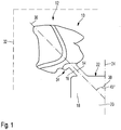
- a positive model 10 of a dental restoration 12 is shown together with its position in space.
- an axis 14 of a feeder channel 16 extends transversely through the positive model 10, starting from a muffle mandrel 18 or press channel 20, more precisely, from its end face 22, at a predetermined angle to an axis 24 of the muffle mandrel 18 or press channel 20, which is 45 ° here.
- the tooth position of the dental restoration or the dental restorations is first recorded.
- the selection of the material for the ceramic to be used also results from the definition of the press concept.
- the dental restoration is determined to match its neighboring teeth in terms of its shape, arrangement in the oral cavity and so on, based on a digital scan of the patient's mouth. From this, the volume of the respective dental restoration is automatically calculated, which also gives the total volume of the dental restorations according to the invention to be produced at the same time.
- the position of the dental restoration in relation to the neighboring teeth is also determined by the CAD software, i.e. in the mesial / distal direction, in the occlusal / cervical direction, in the rotational position around the tooth axis and so on. This also includes the course of the wall thickness of the dental restoration or the positive model.
- the position of the positive model 10 in a virtual space 32 is determined according to the invention based on a special module of the CAD software.
- the total volume is 1.9 cm 3 , so that a muffle of 200 g is sufficient; this includes a corresponding muffle base with a corresponding muffle mandrel 18.
- the positive model has 10 according to Fig. 1 a proportion of 0.4 cm 3 , while a total of 6 further positive models, which are not shown here, extend in the virtual space 32 in a circular or conical manner starting from the muffle mandrel 18 in a corresponding alignment to the alignment of the positive model 10.
- the press concept is intended for a press furnace with ring heating;
- the possible range of the angle 30 is limited to values between, for example, 25 ° and 50 °, and the virtual space 32 is correspondingly smaller compared to a furnace with floor heating.
- the module now generates an optimized arrangement of the positive models 10 in space based on an edge distance to the edge of the muffle of, for example, 10 mm.
- the dental restorations 12 are shifted further towards the outer circumference, but taking into account the edge distances.
- the distance from the end face 22 to the upper end of the virtual space 32 is also limited in the example, here to 16 mm, and 3 mm to 8 mm are specified as the default length for the length of the feeder channel.
- the total length of the dental restoration 12 along the axis 14 and including the length of the feeder channel 16 is as specified per software module in this exemplary embodiment 16 mm, and the minimum distance between the dental restorations 12 is 3 mm.
- angle 30 results in the primary arrangement within a thermal corridor which has a similar temperature range.
- the alignment of the dental restoration 16 in relation to the axis 14 also contributes to this, but also the choice of the docking point 34.
- the angle 30 is determined specifically for the furnace in accordance with the alignment of the isothermal corridor.
- the docking point 34 is selected where the wall thickness of the positive model 10 or the dental restoration 12 is maximum, in the example on a mesiobuccal cusp.
- the alignment of the dental restoration 12 in relation to the axis 14 now takes place in such a way that a virtual axis 36 of the dental restoration, which extends through it from the point of the thickest wall thickness to the most distant point of the dental restoration, that is to say the maximum longitudinal extent of this, also extends the axis 14 of the feeder channel 16 coincides and thus extends as an extension of this.
- Fig. 2 in comparison with Fig. 1 As can be seen, this does not mean a coaxial, that is to say exactly coincident arrangements, but an extension, for example with a possible angular deviation of 15 °, in which case reference is made to the following explanation with regard to optimization.
- a feeder channel 16 is now selected from the library of feeder channels, and the overall arrangement of the positive models 10, including the feeder channels 16, is thus determined via the module.
- the overall arrangement of the positive models 10 and feeder channels 16 is now generated by rapid prototyping, which - at least in the present case - has a tree-shaped arrangement.
- the creation of the positive model arrangement takes place in a residue-free removable material such as polyacrylic, or any other suitable polymer that is suitable for rapid prototyping processing and is characterized by particularly good dimensional accuracy.
- the basal surface of the object extends downwards / outwards, based on the muffle mandrel 18.
- the arrangement of the dental restorations 12 or positive models 10 in the top view is based on the cake principle, so that the smallest width of the positive models 10 inside, so the press channel axis 24 is aligned facing.
- the basic alignment of the positive model 10 takes place in the direction of flow, that is, in accordance with the extension of the axis 14.
- the virtual axis 36 of the dental restoration is slightly oblique to the axis 14 of the feeder channel 16. This minimizes the flow deflection so that the main flow of the flowable dental material through the corresponding cavity occurs just below the longitudinal fissure of the molar there, but at least one closer to the occlusal direction than it is from Fig. 1 can be seen.
- the alignment takes place in such a way that the main direction of flow in each case runs through the center of the crown.
- the feeder channel 16 extends from a point of the end face 22 that is located quite far to the outside. It is quite short, only 3 mm in the example, it being understood that a greater length of the feeder channel is also possible if more objects are to be accommodated in the virtual space 32.
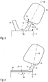
- Fig. 3 it can be seen in what way an anterior crown can extend.
- a blind channel 40 is provided as an additional feed channel 16, which is also created by rapid prototyping - Extends to the feed channel 16 of the dental restoration 10.
- radii 42, 44 are provided on the inlet side of the positive model, which are aerodynamically favorable and also prevent plaster bars, which would otherwise exist there, from breaking off due to the pressure and contaminating the dental restoration.
- a feeder base 46 is formed on the end face 22 of the muffle mandrel 18, which is also produced by rapid prototyping.
- the feeder base 46 establishes the connection between the various feeder channels 16, and at the same time rests against the end face 22 or is anchored there by means of form-fitting means or by means of an adhesive connection.
- the docking point 34 is shown in the arrangement Fig. 3 provided approximately in the middle in the incisal area. This results in a maximized length of the virtual axis 36 such that it extends essentially in the extension of the axis 14.
- stereolithography is preferably used for rapid prototyping. This does not allow any negative layers, so that, for technical reasons, the feeder channel 16 is shifted radially outward - in relation to the axis 24.
- the docking point 34 is hereby compared to Fig. 3 shifted into the approximal area, and the axis 36 extends more obliquely than at Fig. 3 to the axis 14 of the feeder channel 16.
- a correspondingly widened feeder base 46 can be seen, and also the manner in which the material of the feeder base 46 can pass through a recess 48 in the muffle mandrel 18 and reach behind in order to achieve secure anchoring of the feeder base 46.
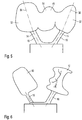
- Fig. 5 the arrangement of a bridge 49 is shown as a dental restoration.
- the feeder channels 16 extend to the abutment teeth 50 and 52 in the occlusal area thereof, while the bridge member 54 remains free of feeder channels.
- the virtual axes 36 extend through the longest possible extension of the abutment teeth 52 in the extension of the axes 14 of the feeder channels 16. Due to the higher volume of the dental restoration or its weight, only the use of a 200 g muffle and the feeder channels come into consideration here are extended to 5 mm in view of the more voluminous dimensions.
- the realization of a bridge does not exclude that single-tooth dental restorations or their positive models can be formed at the same time and in the same muffle; for example, the dental restoration 12 according to FIG Fig. 6 at a different angular position than the bridge 49 according to Fig. 5 be trained at the same time.
- Fig. 7 a further arrangement of a dental restoration 12, namely a posterior crown, in relation to its feeder channel 16 can be seen.
- Mesiopalatal cusps 58 are selected as the docking point 34 and the CAD software module now rotates the dental restoration 12 or the positive model 10 in such a way that the length L of the virtual axis 36 through the dental restoration 12 is maximized.
- the dental material When the dental material flows in, it is filled from the docking point in the direction of flow essentially with a uniform dental material front. This leads to the basal area 62 being filled with dental material before the likewise basal area 64 which is furthest away from the docking point 34, but which is arranged somewhat more cervically, is filled.
- the dental ceramic front therefore initially experiences a resistance in the area 62, which then gradually increases until the area 64 is also filled.
- This somewhat more even pressure increase is beneficial for two reasons: on the one hand, it allows a pressure reduction just before the actual filling has taken place, in order to avoid an abrupt pressure peak at the end of filling. On the other hand, the risk of muffle cracks due to a pressure surge at the end of filling is reduced, so that the end of filling is evened out.
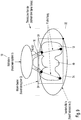
- FIG. 8 it can be seen in which way a further dental restoration 12 can extend in space.
- a conical isothermal corridor 70 is shown schematically, within which the plurality of dental restorations 12, of which in FIG Fig. 8 one is shown extend.
- the end face 22 is adjacent the lower end 72 of the corridor 70, and the upper end is formed by the upper end of the virtual space 32.
- An envelope 74 extends around each dental restoration 12 and serves to maintain the distance and prevents the dental restoration 12 from being moved too close to adjacent dental restorations. This is in Fig. 8 shown schematically as a rectangle, but in practice the smallest possible space that maintains a distance of 3 mm or 2 mm from the dental restoration 12.
- the docking point 34 is set in the upper third at the thickest point of the inlay.
- the axis 36 is arranged while maximizing the length L as an extension of an axis of the feeder 16, not shown here.
- the direction of flow of the dental ceramic front runs approximately in the middle of the central fissure.
- Fig. 9 a corresponding alignment of a posterior crown 49 using three coordinate systems can be seen by way of example.
- the module calculates an isothermal corridor as a trajectory along which the dental restorations 12 are to extend. At the same time, the possibilities of arranging the dental restorations are limited by the virtual space 32.
- the feeder channels 16 extend at an angle of 45 ° to 60 ° to the horizontal, since a ring heater is used here.
- the third coordinate system is spanned over the envelope 74 of the crown 49, which is again shown here as a rectangle, but is actually an envelope of the dental restoration.
- the direction of flow L of the dental ceramic through the cavities created by the positive model 10 is angled in the extension of the axes of the feeder channels 16, but at an angle of 12 ° with respect to these.
- the spruing takes place in a manner known per se on the incisal surfaces, namely again at the thickest point of each crown, which forms the docking point 34.
- the length of the feeder channels 16 is approximately half the length L of the virtual axis 36. It goes without saying that this value can be adapted to the requirements over a wide range and tends to be somewhat larger for smaller dental restorations and somewhat smaller for larger ones.
Landscapes
- Health & Medical Sciences (AREA)
- Engineering & Computer Science (AREA)
- Animal Behavior & Ethology (AREA)
- Veterinary Medicine (AREA)
- Oral & Maxillofacial Surgery (AREA)
- Dentistry (AREA)
- Epidemiology (AREA)
- Life Sciences & Earth Sciences (AREA)
- Public Health (AREA)
- General Health & Medical Sciences (AREA)
- Manufacturing & Machinery (AREA)
- Chemical & Material Sciences (AREA)
- Ceramic Engineering (AREA)
- Human Computer Interaction (AREA)
- Physics & Mathematics (AREA)
- General Physics & Mathematics (AREA)
- Automation & Control Theory (AREA)
- Dental Tools And Instruments Or Auxiliary Dental Instruments (AREA)
- Dental Prosthetics (AREA)
Claims (24)
- Procédé de production de plusieurs restaurations dentaires,- où, sur la base d'un résultat de balayage d'une situation buccale, une restauration dentaire (12) est conçue par un logiciel de CAO et produite dans un matériau amovible sans résidus tel que la cire ou le polyacrylique, dans une étape de mise en forme, comme modèle positif (10) par enlèvement ou de manière générative, par exemple par prototypage rapide,- ledit modèle positif (10) d'une manière connue en soi est moulé et retiré par l'intermédiaire d'un moufle, et ledit moufle est muni d'un canal de presse (20) qui est relié par un canal d'alimentation (16) à une cavité correspondant au modèle positif (10) pour la restauration dentaire (12) où le lingotin introduit dans le canal de pressage (20) est chauffée et mis sous pression de manière à se déformer et le matériau dentaire destiné à former les restaurations dentaires (12) s'écoule dans la cavité et la remplit par les canaux d'alimentation (16), où- pendant ou à la suite de l'étape de moulage, en fonction des dimensions du moufle par rapport à la taille et à la forme du ou des modèles positifs (10), au moins un des canaux d'alimentation (16) est automatiquement créé par un module du logiciel de CAO pour chaque modèle positif (10),- où le module détermine un espace intérieur virtuel à l'intérieur du moufle pour y disposer les restaurations dentaires (12),- où les canaux d'alimentation (16) sont reliés au canal de presse (20) de telle manière à former un arrangement en forme d'arbre dans lequel le canal de pressage (20) forme le tronc de l'arbre et les canaux d'alimentation (16) forment les branches à la pointe desquelles est prévue l'une des restaurations dentaires (12), où le canal d'alimentation (16) respectif s'étend obliquement à partir du canal de pressage (20) selon un angle (30) compris entre plus de 0° et 130° par rapport à l'axe (24) du canal de pressage (20), essentiellement le long d'un isotherme dans le moufle, et où la résistance à l'écoulement d'un matériau céramique utilisé comme matériau dentaire est ajustée en dimensionnant le canal d'alimentation respectif (16),- où le point ayant l'épaisseur de paroi la plus épaisse du modèle positif (10) est choisi comme point d'ancrage (34) du canal d'alimentation respectif (16) sur la restauration dentaire correspondante (12), et le module aligne le modèle positif (10) par rapport au canal d'alimentation respectif (16) de telle sorte qu'il s'étende dans le prolongement de l'axe (14) du canal d'alimentation respectif (16) et la longueur d'un axe virtuel (36) est maximisée par le modèle positif respectif (10).
- Procédé selon la revendication 1, où la longueur et l'épaisseur de chaque canal d'alimentation (16) par rapport aux autres canaux d'alimentation sont ajustées pour correspondre au volume de la restauration dentaire (12) qui lui est associée, et de telle manière que, pendant le pressage, le remplissage complet de la restauration dentaire (12) se produit simultanément, et ainsi que les canaux d'alimentation pour les grandes restaurations dentaires (12) sont réglés sur une résistance à l'écoulement plus faible et les canaux d'alimentation pour les petites restaurations dentaires (12) sur une résistance à l'écoulement plus élevée, et que notamment la résistance à l'écoulement des canaux d'alimentation est choisie respectivement proportionnellement au poids des restaurations dentaires (12) associées.
- Procédé selon l'une des revendications 1 ou 2, où le module, sur la base de la forme de la restauration dentaire respective (12) et donc du modèle positif respectif (10), en partant du point le plus épais, c'est-à-dire du point ayant la plus grande épaisseur de paroi de celle-ci, détermine une direction d'écoulement primaire pour le matériau dentaire comme étant la direction dans laquelle la section transversale d'écoulement est la plus grande à une distance prédéterminée du point le plus épais, et en ce que l'axe virtuel le plus long (36) est défini par le modèle positif (10) comme une extension de l'axe du canal d'alimentation respectif selon la revendication 1, mais s'écartant vers la direction du flux primaire.
- Procédé selon l'une quelconque des revendications précédentes, où l'orientation de chaque restauration dentaire (12) elle-même et donc du modèle positif (10) respectif lui-même à l'intérieur du moufle est déterminé par le module de telle manière que sa plus grande étendue longitudinale s'étend sensiblement le long d'un isotherme.
- Procédé selon l'une quelconque des revendications précédentes, où la production simultanée de plusieurs restaurations dentaires (12) est disposée sensiblement le long de l'enveloppe d'un cône et répartie uniformément autour du canal de presse (20) qui se termine sensiblement au sommet dudit cône.
- Procédé selon l'une des revendications précédentes, où les canaux d'alimentation sont munis de rayons (42, 44) et/ou de transitions continues tant du côté de l'entrée, c'est-à-dire vers le canal de presse (20), que du côté de la sortie, c'est-à-dire vers la restauration dentaire (12).
- Procédé selon l'une quelconque des revendications précédentes, où chaque canal d'alimentation (16) déterminé par le module avec son axe (14, 24) étendu à travers la restauration dentaire respective (12) détermine l'orientation de la restauration dentaire respective (12) et l'orientation de la restauration dentaire respective (12) est choisie de telle manière que la longueur de passage du canal d'alimentation étendu respectif (16) à travers la restauration dentaire respective (12) est maximisée.
- Procédé selon l'une des revendications précédentes, où l'une des restaurations dentaires (12) est formée comme une couronne ou un bridge (49) et la surface de base de la couronne (49) s'étend dans le prolongement d'un axe de canal de pressage (24) avec son côté ouvert éloigné du canal de pressage (20).
- Procédé selon la revendication 5 ou 6, où l'une des restaurations dentaires (12) est réalisée sous forme de pré-facette ou de facette et la surface de base de la pré-facette ou de la facette s'étend radialement vers l'extérieur par rapport à un axe de canal de pressage (24).
- Procédé selon l'une quelconque des revendications précédentes, où l'orientation de chaque restauration dentaire (12) par rapport à l'axe du canal d'alimentation respectif est choisie de telle manière que le prolongement de l'axe du canal d'alimentation respectif à travers la restauration dentaire (12) respective passe par le centre de masse de la restauration dentaire (12) respective lorsque l'axe du canal d'alimentation respectif est disposé sur le point le plus épais de la restauration dentaire (12) respective.
- Procédé selon l'une des revendications précédentes, où le module relie le canal d'alimentation respectif (16) de manière excentrée par rapport aux surfaces extérieures de la restauration dentaire respective (12), en particulier sensiblement dans le prolongement d'une surface labiale ou buccale.
- Procédé selon l'une des revendications précédentes, où la longueur de chaque canal d'alimentation (16) est déterminée par le module en fonction de la taille et du poids de la restauration dentaire (12) respective, en particulier pour les restaurations dentaires (12) de grande taille telles que les molaires, les couronnes (49) ou les couronnes antérieures maxillaires d'une longueur de 30 à 50 % de la longueur de la direction d'extension principale de la restauration dentaire (12) et pour les restaurations dentaires plus petites (12) telles que les couronnes antérieures mandibulaires d'une longueur de 40 à 65 % de la longueur de la direction d'extension principale de la restauration dentaire (12).
- Procédé selon l'une quelconque des revendications précédentes, où, lorsque plusieurs restaurations dentaires (12) sont disposées dans un moufle, le module définit les canaux d'alimentation de celui-ci de telle manière à espacer les restaurations dentaires (12) de manière régulière, dans un couloir isotherme, et lorsque des lignes de connexion imaginaires sont formées entre elles montent un polyèdre se rapprochant d'un cône.
- Procédé selon l'une des revendications précédentes, où le module accède à une bibliothèque de canaux d'alimentation indiquant différents modèles de profil, longueurs, points d'ancrage et angles (30) de canaux d'alimentation en fonction des tailles et des types de restaurations dentaires (12), et sur la base de ces valeurs, le module détermine ou propose les canaux d'alimentation en termes de longueur, de diamètre et d'angle (30).
- Procédé selon l'une quelconque des revendications précédentes, où l'espace intérieur virtuel pour assurer le positionnement des restaurations dentaires (12) à l'intérieur du moufle dépend de la taille du moufle et libère un espace de placement des restaurations dentaires (12) à l'intérieur du moufle de telle manière que chaque restauration dentaire (12) conserve une distance d'au moins 2 mm, en particulier 10 mm par rapport à la paroi extérieure du moufle et, radialement vers l'intérieur, la hauteur de l'espace intérieur virtuel est inférieure à la hauteur radiale vers l'extérieur.
- Procédé selon l'une des revendications précédentes, où le modèle positif (10) est produit par fraisage et le lingotin fraisée est formée comme un cylindre avec une hauteur de cylindre correspondant à l'espace virtuel (32) comprise entre 15 mm et 50 mm, en particulier environ 40 mm.
- Procédé selon l'une des revendications précédentes, où au moins un canal d'alimentation (16) est formé comme canal aveugle (40), c'est-à-dire sans restauration dentaire (12).
- Appareil de production de céramique dentaire comprenant un dispositif de CAO/FAO pour fournir un moule de presse pour la production de céramique dentaire, où ledit dispositif de CAO/FAO présente un logiciel de CAO qui détermine la forme des restaurations dentaires (12) sur la base d'un résultat de balayage d'une situation orale, et ledit dispositif de CAO/FAO présente un logiciel de FAO qui détermine la configuration d'une pluralité de restaurations dentaires (12) via un moufle perdu, où ledit logiciel de CAO présente un module qui détermine automatiquement la position angulaire et les dimensions d'un canal d'alimentation respectif (16) entre un canal de presse central (20) et une cavité respective pour façonner la restauration dentaire respective (12) dans un espace intérieur virtuel respectif à l'intérieur du cylindre de revêtement, où l'angle d'incidence de la restauration dentaire respective (12) par rapport à l'axe du canal d'alimentation respectif du canal d'alimentation associé (16) est sélectionné en un point d'ancrage (34) du canal d'alimentation (16) sur la restauration dentaire respective (12) au point le plus épais de la restauration dentaire respective (12), peut être déterminé de telle manière que l'extension de l'axe du canal d'alimentation respectif s'étende sur la plus grande longueur possible de la restauration dentaire (12) respective en partant du point le plus épais, en particulier sur la base d'une bibliothèque prédéfinie de formes de restaurations dentaires (12) et/ou de canaux d'alimentation, et où le canal d'alimentation (16) respectif est relié au canal de presse central (20) de telle manière que ceux-ci forment un arrangement en forme d'arbre, où le canal de pressage (20) forme le tronc de l'arbre et les canaux d'alimentation forment les branches, à l'extrémité desquelles est prévue une restauration dentaire (12), et où la résistance à l'écoulement d'un matériau céramique utilisé comme matériau dentaire peut être réglée en dimensionnant le canal d'alimentation (16) respectif.
- Dispositif de fabrication de céramique dentaire selon la revendication 18, où le point d'ancrage (34) de la restauration dentaire respective (12) au canal d'alimentation respectif (16) est choisi par le module à l'endroit où une bille du plus grand diamètre possible s'adapte dans la restauration dentaire respective (12), où le prolongement de l'axe (14, 24) du canal d'alimentation respectif (16) passe en particulier essentiellement par le point central de cette bille.
- Dispositif de production de céramique dentaire selon la revendication 18 ou 19, où chaque restauration dentaire (12) est définie par le module dans l'espace virtuel (32) en termes de disposition et d'orientation de manière à avoir une distance de bord à la fois de la paroi extérieure du moufle et des restaurations dentaires adjacentes (12) qui n'est pas inférieure à une valeur prédéterminée, qui est en particulier de plusieurs millimètres.
- Dispositif de fabrication de céramique dentaire selon l'une des revendications 18 à 20, où le point d'ancrage (34) de la restauration dentaire (12) respective au canal d'alimentation (16) respectif en projection verticale - par rapport au cylindre de pressage - est choisi de telle manière qu'un point étroit de la restauration dentaire (12) respective est disposé radialement vers l'intérieur, c'est-à-dire à proximité du canal d'alimentation. (20), et un point plus large est disposé radialement plus loin vers l'extérieur selon le principe du camembert.
- Dispositif de production de céramique dentaire selon l'une quelconque des revendications 18 à 21, où chaque canal d'alimentation (16) et/ou la restauration dentaire respective (12) est pourvu, à un emplacement basal ou au moins couvert, d'un code ou d'une identification qui facilite l'affectation à l'ordre respectif et/ou aux patients respectifs.
- Dispositif de fabrication de céramique dentaire selon l'une des revendications 18 à 22, où chaque restauration dentaire (12), vue dans la direction de l'axe du canal de pressage (24), présente, pour sa constitution continue et stratifiée, des surfaces enveloppantes qui s'élèvent de manière monotone ou tout au plus restent constantes vers l'extérieur, et ne sont en tout cas -pas' abaissées vers l'extérieur, vu dans chaque cas à partir du point d'ancrage (34) de la restauration dentaire (12) respective en vue latérale de celle-ci.
- Dispositif de production de céramique dentaire selon l'une des revendications précédentes, où le dispositif FAO utilise la face d'extrémité (22) du canal de pressage (20) comme point zéro de l'espace intérieur virtuel et polymérise une base de canal d'alimentation directement sur cette face d'extrémité (22), à partir de laquelle les canaux d'alimentation s'étendent.
Priority Applications (9)
| Application Number | Priority Date | Filing Date | Title |
|---|---|---|---|
| EP14171268.7A EP2952154B1 (fr) | 2014-06-05 | 2014-06-05 | Procédé de fabrication de restaurations dentaires et dispositif de fabrication de céramiques dentaires |
| ES14171268T ES2883207T3 (es) | 2014-06-05 | 2014-06-05 | Procedimiento para la fabricación de varias restauraciones dentales y un dispositivo de producción de cerámica dental |
| US15/115,476 US10058405B2 (en) | 2014-06-05 | 2015-05-22 | Dental restoration model |
| EP15727331.9A EP3151781B1 (fr) | 2014-06-05 | 2015-05-22 | Modele de restauration dentaire |
| CN201580028401.0A CN106456294B (zh) | 2014-06-05 | 2015-05-22 | 牙科修复模型 |
| PCT/EP2015/061410 WO2015185379A1 (fr) | 2014-06-05 | 2015-05-22 | Modèle de restauration dentaire |
| CA2893365A CA2893365C (fr) | 2014-06-05 | 2015-06-02 | Procede de fabrication d'une restauration dentaire ainsi que dispositif de production de produit ceramique dentaire |
| US14/732,547 US10816955B2 (en) | 2014-06-05 | 2015-06-05 | Process and device for manufacturing a dental restoration |
| US17/080,198 US20210041852A1 (en) | 2014-06-05 | 2020-10-26 | Process and Device for Manufacturing a Dental Restoration |
Applications Claiming Priority (1)
| Application Number | Priority Date | Filing Date | Title |
|---|---|---|---|
| EP14171268.7A EP2952154B1 (fr) | 2014-06-05 | 2014-06-05 | Procédé de fabrication de restaurations dentaires et dispositif de fabrication de céramiques dentaires |
Publications (2)
| Publication Number | Publication Date |
|---|---|
| EP2952154A1 EP2952154A1 (fr) | 2015-12-09 |
| EP2952154B1 true EP2952154B1 (fr) | 2021-05-05 |
Family
ID=50927943
Family Applications (1)
| Application Number | Title | Priority Date | Filing Date |
|---|---|---|---|
| EP14171268.7A Active EP2952154B1 (fr) | 2014-06-05 | 2014-06-05 | Procédé de fabrication de restaurations dentaires et dispositif de fabrication de céramiques dentaires |
Country Status (4)
| Country | Link |
|---|---|
| US (2) | US10816955B2 (fr) |
| EP (1) | EP2952154B1 (fr) |
| CA (1) | CA2893365C (fr) |
| ES (1) | ES2883207T3 (fr) |
Cited By (1)
| Publication number | Priority date | Publication date | Assignee | Title |
|---|---|---|---|---|
| EP4534042A1 (fr) * | 2023-10-06 | 2025-04-09 | Herting, Torsten | Procédé de fabrication de dents prothétiques et préformes associées |
Families Citing this family (13)
| Publication number | Priority date | Publication date | Assignee | Title |
|---|---|---|---|---|
| EP3151781B1 (fr) * | 2014-06-05 | 2018-10-17 | Ivoclar Vivadent AG | Modele de restauration dentaire |
| WO2016094272A1 (fr) | 2014-12-09 | 2016-06-16 | 3M Innovative Properties Company | Techniques de moulage de restauration dentaire |
| AU2016370731B2 (en) | 2015-12-17 | 2019-05-09 | Solventum Intellectual Properties Company | One-piece dental restoration molds |
| AU2016370745B2 (en) | 2015-12-17 | 2019-10-24 | Solventum Intellectual Properties Company | Dental restoration molds |
| EP3235467B1 (fr) | 2016-04-22 | 2021-03-31 | Ivoclar Vivadent AG | Méthode de fabrication d'une restauration dentaire |
| US11547530B2 (en) | 2016-07-26 | 2023-01-10 | 3M Innovative Properties Company | Dental restoration molds |
| EP3957267B1 (fr) | 2016-07-26 | 2024-08-28 | Solventum Intellectual Properties Company | Moules de restauration dentaire |
| US11801126B2 (en) | 2017-09-19 | 2023-10-31 | 3M Innovative Properties Company | Dental restoration molds |
| CN218474653U (zh) | 2018-08-10 | 2023-02-14 | 3M创新有限公司 | 用于在患者的口部中形成牙修复体的定制工具 |
| US12491047B2 (en) * | 2018-10-25 | 2025-12-09 | Solventum Intellectual Property Company | 3D-printed dental restoration precursor with support element and process of production |
| CN111400934B (zh) * | 2020-04-15 | 2023-04-07 | 天华化工机械及自动化研究设计院有限公司 | 基于workbench低温碳化炉氧含量分布模拟方法 |
| US12201490B2 (en) | 2021-08-30 | 2025-01-21 | Solventum Intellectual Properties Compay | Digital design of dental matrix with improved customized interproximal contacts |
| US20230390034A1 (en) * | 2022-06-03 | 2023-12-07 | B & D Dental Corporation | Certificate System for Tracking Dental Material as it Becomes a Prosthetic |
Citations (1)
| Publication number | Priority date | Publication date | Assignee | Title |
|---|---|---|---|---|
| US20080153069A1 (en) * | 2006-12-22 | 2008-06-26 | Stephan Holzner | Method, machine-readable medium and computer concerning the manufacture of dental prostheses |
Family Cites Families (39)
| Publication number | Priority date | Publication date | Assignee | Title |
|---|---|---|---|---|
| US4081019A (en) * | 1975-12-11 | 1978-03-28 | The J. M. Ney Company | Synthetic resin preform and sprue assembly and method of making same |
| US4161208A (en) * | 1977-12-05 | 1979-07-17 | Cooper Abraham J | Investment casting apparatus |
| DE3203937C2 (de) * | 1982-02-05 | 1985-10-03 | Luc Dr. 4150 Krefeld Barrut | Verfahren und Vorrichtung zum maschinellen Sanieren oder Korrigieren mindestens eines Zahnes oder zum maschinellen Vorbereiten mindestens eines Zahnes für eine festsitzende prothetische Restaurierung und zum maschinellen Herstellen der festsitzenden prothetischen Restaurierung |
| BE1008372A3 (nl) | 1994-04-19 | 1996-04-02 | Materialise Nv | Werkwijze voor het vervaardigen van een geperfektioneerd medisch model uitgaande van digitale beeldinformatie van een lichaamsdeel. |
| JP3672966B2 (ja) * | 1995-04-14 | 2005-07-20 | 株式会社ユニスン | 歯科用予測模型の作成方法および作成装置 |
| DE19612699C5 (de) * | 1996-03-29 | 2004-03-04 | Sirona Dental Systems Gmbh | Rohling zur Herstellung eines zahntechnischen Formteils |
| US5823778A (en) * | 1996-06-14 | 1998-10-20 | The United States Of America As Represented By The Secretary Of The Air Force | Imaging method for fabricating dental devices |
| JPH1075963A (ja) * | 1996-09-06 | 1998-03-24 | Nikon Corp | 歯科補綴物モデルの設計方法およびこの方法を実行するプログラムを記録した媒体 |
| US5879158A (en) * | 1997-05-20 | 1999-03-09 | Doyle; Walter A. | Orthodontic bracketing system and method therefor |
| US6303059B1 (en) * | 1999-03-26 | 2001-10-16 | Ivoclar A.G. | Method of controlling an oven |
| US20010023056A1 (en) * | 2000-03-15 | 2001-09-20 | Ivoclar Vivadent Ag | Dental device |
| EP1420714B1 (fr) * | 2001-08-31 | 2007-03-21 | Cynovad, Inc. | Procede de production de moules a fondre |
| AT411816B (de) | 2002-07-19 | 2004-06-25 | Mediceram Chirurgische Implant | Verfahren zur herstellung einer belastbaren struktur aus oxidkeramik, insbesondere aus zirkondioxid |
| US7658610B2 (en) * | 2003-02-26 | 2010-02-09 | Align Technology, Inc. | Systems and methods for fabricating a dental template with a 3-D object placement |
| US7600999B2 (en) * | 2003-02-26 | 2009-10-13 | Align Technology, Inc. | Systems and methods for fabricating a dental template |
| US7955159B2 (en) * | 2003-08-07 | 2011-06-07 | Ivoclar Vivadent Ag | Machining of ceramic materials |
| EP1506745A1 (fr) * | 2003-08-15 | 2005-02-16 | Jeanette Mörmann | Ebauche et procédé de fabrication d'une restauration dentaire |
| US7445449B2 (en) * | 2004-02-06 | 2008-11-04 | Robert David Sager | Continuous production crown core/crown making process |
| DE102004014573A1 (de) * | 2004-03-25 | 2005-10-27 | BEGO Bremer Goldschlägerei Wilh. Herbst GmbH & Co. KG | Verfahren zur Herstellung einer Muffel für den Fein- oder Modellguss, Verfahren zum Herstellen eines metallischen, keramischen oder glaskeramischen Guss- oder Pressobjekts und Kit zur Herstellung eines solchen Objekts |
| US7236842B2 (en) * | 2004-12-02 | 2007-06-26 | Cadent Ltd. | System and method for manufacturing a dental prosthesis and a dental prosthesis manufactured thereby |
| US20090081613A1 (en) * | 2005-03-24 | 2009-03-26 | Biomed Est. | Implant analog |
| DE102005055526A1 (de) * | 2005-11-22 | 2007-06-06 | BEGO Bremer Goldschlägerei Wilh. Herbst GmbH & Co. KG | Verfahren und System zum Erzeugen einer dentalen Prothese |
| EP2117750A2 (fr) * | 2006-11-07 | 2009-11-18 | Geodigm Corporation | Dispositifs de formage de descente de coulée |
| US20090148816A1 (en) * | 2007-01-11 | 2009-06-11 | Geodigm Corporation | Design of dental appliances |
| EP2109414A2 (fr) * | 2007-01-11 | 2009-10-21 | Geodigm Corporation | Conception d'appareils dentaires |
| JP5209725B2 (ja) * | 2007-09-27 | 2013-06-12 | スリーエム イノベイティブ プロパティズ カンパニー | 歯科矯正技工器具を製造するための歯科模型のデジタル形成方法 |
| DE102007056820A1 (de) * | 2007-11-23 | 2009-06-18 | Sirona Dental Systems Gmbh | Messkörper für ein Implantat und Verfahren zur Erstellung einer 3D-Messaufnahme |
| DE102008017784B4 (de) * | 2008-04-08 | 2014-04-17 | Ivoclar Vivadent Ag | Vorrichtung zum Anfertigen einer Muffel |
| US8509932B2 (en) * | 2008-07-17 | 2013-08-13 | Cadent Ltd. | Methods, systems and accessories useful for procedures relating to dental implants |
| US8255071B2 (en) * | 2008-11-13 | 2012-08-28 | Innovative Health Technologies, Llc | Method and system for forming a dental prosthesis |
| CA2690407C (fr) * | 2009-01-16 | 2016-12-20 | Michel Poirier | Appareil de prothese dentaire |
| BRPI1009891B8 (pt) * | 2009-03-20 | 2021-06-22 | 3Shape As | sistema e método para planejamento, visualização e otimização de restaurações dentárias |
| US8753114B2 (en) * | 2010-02-26 | 2014-06-17 | William C. Vuillemot | Method for dental restoration and related kit |
| DE102010064142B4 (de) * | 2010-12-23 | 2019-06-13 | BEGO Bremer Goldschlägerei Wilh. Herbst GmbH & Co. KG | Einbettmasse zur Verwendung in einem Verfahren zur Herstellung einer Dental-Restauration mittels CAD-Cast-Verfahren |
| EP2551621B1 (fr) * | 2011-07-25 | 2017-10-04 | Ivoclar Vivadent AG | Four dentaire |
| WO2014009955A1 (fr) * | 2012-07-12 | 2014-01-16 | Pomodent Dental Ltd. | Ensemble butée pour implants dentaires |
| US10064709B2 (en) * | 2013-02-15 | 2018-09-04 | Jean J. Elnajjar | Separable segmented casting ring for making investment molds |
| EP2952155B1 (fr) * | 2014-06-06 | 2020-07-22 | Ivoclar Vivadent AG | Dispositif de fabrication de céramique dentaire |
| DE102015108178A1 (de) * | 2015-05-22 | 2016-11-24 | Degudent Gmbh | Verfahren zum Herstellen einer dentalen Struktur sowie dentale Struktur |
-
2014
- 2014-06-05 EP EP14171268.7A patent/EP2952154B1/fr active Active
- 2014-06-05 ES ES14171268T patent/ES2883207T3/es active Active
-
2015
- 2015-06-02 CA CA2893365A patent/CA2893365C/fr active Active
- 2015-06-05 US US14/732,547 patent/US10816955B2/en active Active
-
2020
- 2020-10-26 US US17/080,198 patent/US20210041852A1/en active Pending
Patent Citations (1)
| Publication number | Priority date | Publication date | Assignee | Title |
|---|---|---|---|---|
| US20080153069A1 (en) * | 2006-12-22 | 2008-06-26 | Stephan Holzner | Method, machine-readable medium and computer concerning the manufacture of dental prostheses |
Cited By (2)
| Publication number | Priority date | Publication date | Assignee | Title |
|---|---|---|---|---|
| EP4534042A1 (fr) * | 2023-10-06 | 2025-04-09 | Herting, Torsten | Procédé de fabrication de dents prothétiques et préformes associées |
| WO2025073773A1 (fr) * | 2023-10-06 | 2025-04-10 | Herting Torsten | Ébauches de dents prothétiques et procédé de production de prothèse dentaire |
Also Published As
| Publication number | Publication date |
|---|---|
| CA2893365C (fr) | 2022-06-14 |
| CA2893365A1 (fr) | 2015-12-05 |
| US20210041852A1 (en) | 2021-02-11 |
| EP2952154A1 (fr) | 2015-12-09 |
| US20160089220A1 (en) | 2016-03-31 |
| US10816955B2 (en) | 2020-10-27 |
| ES2883207T3 (es) | 2021-12-07 |
Similar Documents
| Publication | Publication Date | Title |
|---|---|---|
| EP2952154B1 (fr) | Procédé de fabrication de restaurations dentaires et dispositif de fabrication de céramiques dentaires | |
| EP2862540B1 (fr) | Dispositif de positionnement dentaire | |
| EP3649983B1 (fr) | Procédé de fabrication de prothèses dentaires | |
| EP2410939B1 (fr) | Dispositif de façonnage de gencive et procédé de fabrication de la structure d'un dispositif de façonnage de gencive | |
| WO1999047065A1 (fr) | Couronnes dentaires et/ou bridges dentaires | |
| EP3612131B1 (fr) | Procédé de fabrication d'une prothèse dentaire à racines parallèles des dents de la prothèse | |
| DE102017113814B4 (de) | Verfahren zur Herstellung einer Dentalprothese mit definiertem Klebespalt | |
| DE102011119839B4 (de) | Herstellen von Suprakonstruktionen auf einer SLM-Anlage mit anschließender Fräsbearbeitung der Anschlussgeometrie | |
| EP2952155B1 (fr) | Dispositif de fabrication de céramique dentaire | |
| WO2015055790A1 (fr) | Gabarit de transfert dentaire | |
| EP4326187B1 (fr) | Ébauche de prothèse dentaire et son procédé de fabrication, utilisation de l'ébauche et procédé de fabrication d'une restauration dentaire à partir de l'ébauche | |
| EP0806932B1 (fr) | Element de restauration dentaire et de prothese en materiau ceramique et son procede de production | |
| DE102015106424A1 (de) | Verfahren zur Herstellung von Zahnersatz mit einem Kunststoffkern | |
| EP3157460B1 (fr) | Base de prothèse et procédé pour relier par liaison de matière au moins une dent artificielle à une base de prothèse | |
| WO2015055793A1 (fr) | Gabarit de transfert dentaire | |
| EP3445274B1 (fr) | Courbure de pas de dent et procede de production d'une courbure de pas de dent | |
| EP3151781B1 (fr) | Modele de restauration dentaire | |
| EP3705078B1 (fr) | Procédé de fabrication d'un porte-empreinte individuel | |
| EP3064169B1 (fr) | Procédé de fabrication de pièces céramiques dentaires et appareils pour la fabrication de pièces de céramique dentaire | |
| WO2022238049A1 (fr) | Procédé et dispositif de production d'une prothèse dentaire | |
| EP0943295A1 (fr) | Méthode pour la fabrication de couronnes et/ou ponts dentaires | |
| EP3923854A1 (fr) | Ébauche servant à la fabrication d'une restauration dentaire, et procédé pour sa fabrication | |
| EP2664296A2 (fr) | Procédé de fabrication d'une prothèse dentaire |
Legal Events
| Date | Code | Title | Description |
|---|---|---|---|
| PUAI | Public reference made under article 153(3) epc to a published international application that has entered the european phase |
Free format text: ORIGINAL CODE: 0009012 |
|
| AK | Designated contracting states |
Kind code of ref document: A1 Designated state(s): AL AT BE BG CH CY CZ DE DK EE ES FI FR GB GR HR HU IE IS IT LI LT LU LV MC MK MT NL NO PL PT RO RS SE SI SK SM TR |
|
| AX | Request for extension of the european patent |
Extension state: BA ME |
|
| 17P | Request for examination filed |
Effective date: 20160404 |
|
| RBV | Designated contracting states (corrected) |
Designated state(s): AL AT BE BG CH CY CZ DE DK EE ES FI FR GB GR HR HU IE IS IT LI LT LU LV MC MK MT NL NO PL PT RO RS SE SI SK SM TR |
|
| STAA | Information on the status of an ep patent application or granted ep patent |
Free format text: STATUS: EXAMINATION IS IN PROGRESS |
|
| 17Q | First examination report despatched |
Effective date: 20161215 |
|
| RIC1 | Information provided on ipc code assigned before grant |
Ipc: A61C 13/083 20060101ALI20200402BHEP Ipc: A61C 5/77 20170101ALI20200402BHEP Ipc: A61C 13/00 20060101AFI20200402BHEP |
|
| GRAP | Despatch of communication of intention to grant a patent |
Free format text: ORIGINAL CODE: EPIDOSNIGR1 |
|
| STAA | Information on the status of an ep patent application or granted ep patent |
Free format text: STATUS: GRANT OF PATENT IS INTENDED |
|
| INTG | Intention to grant announced |
Effective date: 20200917 |
|
| GRAS | Grant fee paid |
Free format text: ORIGINAL CODE: EPIDOSNIGR3 |
|
| RIN1 | Information on inventor provided before grant (corrected) |
Inventor name: EBERT, JOERG Inventor name: VOIGT, OLIVER Inventor name: SPECHT, TOBIAS Inventor name: GRUENDENFELDER, ROBERT |
|
| GRAA | (expected) grant |
Free format text: ORIGINAL CODE: 0009210 |
|
| STAA | Information on the status of an ep patent application or granted ep patent |
Free format text: STATUS: THE PATENT HAS BEEN GRANTED |
|
| AK | Designated contracting states |
Kind code of ref document: B1 Designated state(s): AL AT BE BG CH CY CZ DE DK EE ES FI FR GB GR HR HU IE IS IT LI LT LU LV MC MK MT NL NO PL PT RO RS SE SI SK SM TR |
|
| REG | Reference to a national code |
Ref country code: GB Ref legal event code: FG4D Free format text: NOT ENGLISH |
|
| REG | Reference to a national code |
Ref country code: CH Ref legal event code: EP |
|
| REG | Reference to a national code |
Ref country code: AT Ref legal event code: REF Ref document number: 1388847 Country of ref document: AT Kind code of ref document: T Effective date: 20210515 |
|
| REG | Reference to a national code |
Ref country code: DE Ref legal event code: R096 Ref document number: 502014015538 Country of ref document: DE |
|
| REG | Reference to a national code |
Ref country code: IE Ref legal event code: FG4D Free format text: LANGUAGE OF EP DOCUMENT: GERMAN |
|
| REG | Reference to a national code |
Ref country code: NL Ref legal event code: FP |
|
| REG | Reference to a national code |
Ref country code: LT Ref legal event code: MG9D |
|
| PG25 | Lapsed in a contracting state [announced via postgrant information from national office to epo] |
Ref country code: HR Free format text: LAPSE BECAUSE OF FAILURE TO SUBMIT A TRANSLATION OF THE DESCRIPTION OR TO PAY THE FEE WITHIN THE PRESCRIBED TIME-LIMIT Effective date: 20210505 Ref country code: LT Free format text: LAPSE BECAUSE OF FAILURE TO SUBMIT A TRANSLATION OF THE DESCRIPTION OR TO PAY THE FEE WITHIN THE PRESCRIBED TIME-LIMIT Effective date: 20210505 Ref country code: FI Free format text: LAPSE BECAUSE OF FAILURE TO SUBMIT A TRANSLATION OF THE DESCRIPTION OR TO PAY THE FEE WITHIN THE PRESCRIBED TIME-LIMIT Effective date: 20210505 Ref country code: BG Free format text: LAPSE BECAUSE OF FAILURE TO SUBMIT A TRANSLATION OF THE DESCRIPTION OR TO PAY THE FEE WITHIN THE PRESCRIBED TIME-LIMIT Effective date: 20210805 |
|
| PG25 | Lapsed in a contracting state [announced via postgrant information from national office to epo] |
Ref country code: IS Free format text: LAPSE BECAUSE OF FAILURE TO SUBMIT A TRANSLATION OF THE DESCRIPTION OR TO PAY THE FEE WITHIN THE PRESCRIBED TIME-LIMIT Effective date: 20210905 Ref country code: GR Free format text: LAPSE BECAUSE OF FAILURE TO SUBMIT A TRANSLATION OF THE DESCRIPTION OR TO PAY THE FEE WITHIN THE PRESCRIBED TIME-LIMIT Effective date: 20210806 Ref country code: LV Free format text: LAPSE BECAUSE OF FAILURE TO SUBMIT A TRANSLATION OF THE DESCRIPTION OR TO PAY THE FEE WITHIN THE PRESCRIBED TIME-LIMIT Effective date: 20210505 Ref country code: NO Free format text: LAPSE BECAUSE OF FAILURE TO SUBMIT A TRANSLATION OF THE DESCRIPTION OR TO PAY THE FEE WITHIN THE PRESCRIBED TIME-LIMIT Effective date: 20210805 Ref country code: PT Free format text: LAPSE BECAUSE OF FAILURE TO SUBMIT A TRANSLATION OF THE DESCRIPTION OR TO PAY THE FEE WITHIN THE PRESCRIBED TIME-LIMIT Effective date: 20210906 Ref country code: PL Free format text: LAPSE BECAUSE OF FAILURE TO SUBMIT A TRANSLATION OF THE DESCRIPTION OR TO PAY THE FEE WITHIN THE PRESCRIBED TIME-LIMIT Effective date: 20210505 Ref country code: SE Free format text: LAPSE BECAUSE OF FAILURE TO SUBMIT A TRANSLATION OF THE DESCRIPTION OR TO PAY THE FEE WITHIN THE PRESCRIBED TIME-LIMIT Effective date: 20210505 Ref country code: RS Free format text: LAPSE BECAUSE OF FAILURE TO SUBMIT A TRANSLATION OF THE DESCRIPTION OR TO PAY THE FEE WITHIN THE PRESCRIBED TIME-LIMIT Effective date: 20210505 |
|
| REG | Reference to a national code |
Ref country code: ES Ref legal event code: FG2A Ref document number: 2883207 Country of ref document: ES Kind code of ref document: T3 Effective date: 20211207 |
|
| PG25 | Lapsed in a contracting state [announced via postgrant information from national office to epo] |
Ref country code: RO Free format text: LAPSE BECAUSE OF FAILURE TO SUBMIT A TRANSLATION OF THE DESCRIPTION OR TO PAY THE FEE WITHIN THE PRESCRIBED TIME-LIMIT Effective date: 20210505 Ref country code: SK Free format text: LAPSE BECAUSE OF FAILURE TO SUBMIT A TRANSLATION OF THE DESCRIPTION OR TO PAY THE FEE WITHIN THE PRESCRIBED TIME-LIMIT Effective date: 20210505 Ref country code: SM Free format text: LAPSE BECAUSE OF FAILURE TO SUBMIT A TRANSLATION OF THE DESCRIPTION OR TO PAY THE FEE WITHIN THE PRESCRIBED TIME-LIMIT Effective date: 20210505 Ref country code: DK Free format text: LAPSE BECAUSE OF FAILURE TO SUBMIT A TRANSLATION OF THE DESCRIPTION OR TO PAY THE FEE WITHIN THE PRESCRIBED TIME-LIMIT Effective date: 20210505 Ref country code: EE Free format text: LAPSE BECAUSE OF FAILURE TO SUBMIT A TRANSLATION OF THE DESCRIPTION OR TO PAY THE FEE WITHIN THE PRESCRIBED TIME-LIMIT Effective date: 20210505 Ref country code: CZ Free format text: LAPSE BECAUSE OF FAILURE TO SUBMIT A TRANSLATION OF THE DESCRIPTION OR TO PAY THE FEE WITHIN THE PRESCRIBED TIME-LIMIT Effective date: 20210505 |
|
| REG | Reference to a national code |
Ref country code: DE Ref legal event code: R097 Ref document number: 502014015538 Country of ref document: DE |
|
| PLBE | No opposition filed within time limit |
Free format text: ORIGINAL CODE: 0009261 |
|
| STAA | Information on the status of an ep patent application or granted ep patent |
Free format text: STATUS: NO OPPOSITION FILED WITHIN TIME LIMIT |
|
| PG25 | Lapsed in a contracting state [announced via postgrant information from national office to epo] |
Ref country code: MC Free format text: LAPSE BECAUSE OF FAILURE TO SUBMIT A TRANSLATION OF THE DESCRIPTION OR TO PAY THE FEE WITHIN THE PRESCRIBED TIME-LIMIT Effective date: 20210505 Ref country code: LU Free format text: LAPSE BECAUSE OF NON-PAYMENT OF DUE FEES Effective date: 20210605 |
|
| 26N | No opposition filed |
Effective date: 20220208 |
|
| PG25 | Lapsed in a contracting state [announced via postgrant information from national office to epo] |
Ref country code: IE Free format text: LAPSE BECAUSE OF NON-PAYMENT OF DUE FEES Effective date: 20210605 |
|
| PG25 | Lapsed in a contracting state [announced via postgrant information from national office to epo] |
Ref country code: IS Free format text: LAPSE BECAUSE OF FAILURE TO SUBMIT A TRANSLATION OF THE DESCRIPTION OR TO PAY THE FEE WITHIN THE PRESCRIBED TIME-LIMIT Effective date: 20210905 Ref country code: AL Free format text: LAPSE BECAUSE OF FAILURE TO SUBMIT A TRANSLATION OF THE DESCRIPTION OR TO PAY THE FEE WITHIN THE PRESCRIBED TIME-LIMIT Effective date: 20210505 |
|
| PG25 | Lapsed in a contracting state [announced via postgrant information from national office to epo] |
Ref country code: HU Free format text: LAPSE BECAUSE OF FAILURE TO SUBMIT A TRANSLATION OF THE DESCRIPTION OR TO PAY THE FEE WITHIN THE PRESCRIBED TIME-LIMIT; INVALID AB INITIO Effective date: 20140605 |
|
| PG25 | Lapsed in a contracting state [announced via postgrant information from national office to epo] |
Ref country code: CY Free format text: LAPSE BECAUSE OF FAILURE TO SUBMIT A TRANSLATION OF THE DESCRIPTION OR TO PAY THE FEE WITHIN THE PRESCRIBED TIME-LIMIT Effective date: 20210505 |
|
| P01 | Opt-out of the competence of the unified patent court (upc) registered |
Effective date: 20230607 |
|
| PGFP | Annual fee paid to national office [announced via postgrant information from national office to epo] |
Ref country code: AT Payment date: 20230509 Year of fee payment: 10 |
|
| PG25 | Lapsed in a contracting state [announced via postgrant information from national office to epo] |
Ref country code: MK Free format text: LAPSE BECAUSE OF FAILURE TO SUBMIT A TRANSLATION OF THE DESCRIPTION OR TO PAY THE FEE WITHIN THE PRESCRIBED TIME-LIMIT Effective date: 20210505 |
|
| PG25 | Lapsed in a contracting state [announced via postgrant information from national office to epo] |
Ref country code: MT Free format text: LAPSE BECAUSE OF FAILURE TO SUBMIT A TRANSLATION OF THE DESCRIPTION OR TO PAY THE FEE WITHIN THE PRESCRIBED TIME-LIMIT Effective date: 20210505 |
|
| REG | Reference to a national code |
Ref country code: AT Ref legal event code: MM01 Ref document number: 1388847 Country of ref document: AT Kind code of ref document: T Effective date: 20240605 |
|
| PG25 | Lapsed in a contracting state [announced via postgrant information from national office to epo] |
Ref country code: AT Free format text: LAPSE BECAUSE OF NON-PAYMENT OF DUE FEES Effective date: 20240605 |
|
| PGFP | Annual fee paid to national office [announced via postgrant information from national office to epo] |
Ref country code: DE Payment date: 20250623 Year of fee payment: 12 |
|
| PGFP | Annual fee paid to national office [announced via postgrant information from national office to epo] |
Ref country code: GB Payment date: 20250627 Year of fee payment: 12 |
|
| PGFP | Annual fee paid to national office [announced via postgrant information from national office to epo] |
Ref country code: NL Payment date: 20250623 Year of fee payment: 12 |
|
| PGFP | Annual fee paid to national office [announced via postgrant information from national office to epo] |
Ref country code: FR Payment date: 20250627 Year of fee payment: 12 |
|
| PGFP | Annual fee paid to national office [announced via postgrant information from national office to epo] |
Ref country code: ES Payment date: 20250707 Year of fee payment: 12 |
|
| PGFP | Annual fee paid to national office [announced via postgrant information from national office to epo] |
Ref country code: IT Payment date: 20250605 Year of fee payment: 12 |
|
| PGFP | Annual fee paid to national office [announced via postgrant information from national office to epo] |
Ref country code: BE Payment date: 20250618 Year of fee payment: 12 |
|
| PGFP | Annual fee paid to national office [announced via postgrant information from national office to epo] |
Ref country code: CH Payment date: 20250717 Year of fee payment: 12 |
|
| PG25 | Lapsed in a contracting state [announced via postgrant information from national office to epo] |
Ref country code: TR Free format text: LAPSE BECAUSE OF FAILURE TO SUBMIT A TRANSLATION OF THE DESCRIPTION OR TO PAY THE FEE WITHIN THE PRESCRIBED TIME-LIMIT Effective date: 20210505 |