EP2952264B1 - Dispositif de revêtement à rideau - Google Patents
Dispositif de revêtement à rideau Download PDFInfo
- Publication number
- EP2952264B1 EP2952264B1 EP14171250.5A EP14171250A EP2952264B1 EP 2952264 B1 EP2952264 B1 EP 2952264B1 EP 14171250 A EP14171250 A EP 14171250A EP 2952264 B1 EP2952264 B1 EP 2952264B1
- Authority
- EP
- European Patent Office
- Prior art keywords
- edge
- edge guide
- curtain
- guide
- coating device
- Prior art date
- Legal status (The legal status is an assumption and is not a legal conclusion. Google has not performed a legal analysis and makes no representation as to the accuracy of the status listed.)
- Active
Links
Images


Classifications
-
- B—PERFORMING OPERATIONS; TRANSPORTING
- B05—SPRAYING OR ATOMISING IN GENERAL; APPLYING FLUENT MATERIALS TO SURFACES, IN GENERAL
- B05C—APPARATUS FOR APPLYING FLUENT MATERIALS TO SURFACES, IN GENERAL
- B05C11/00—Component parts, details or accessories not specifically provided for in groups B05C1/00 - B05C9/00
-
- B—PERFORMING OPERATIONS; TRANSPORTING
- B05—SPRAYING OR ATOMISING IN GENERAL; APPLYING FLUENT MATERIALS TO SURFACES, IN GENERAL
- B05C—APPARATUS FOR APPLYING FLUENT MATERIALS TO SURFACES, IN GENERAL
- B05C5/00—Apparatus in which liquid or other fluent material is projected, poured or allowed to flow on to the surface of the work
- B05C5/005—Curtain coaters
-
- B—PERFORMING OPERATIONS; TRANSPORTING
- B05—SPRAYING OR ATOMISING IN GENERAL; APPLYING FLUENT MATERIALS TO SURFACES, IN GENERAL
- B05C—APPARATUS FOR APPLYING FLUENT MATERIALS TO SURFACES, IN GENERAL
- B05C5/00—Apparatus in which liquid or other fluent material is projected, poured or allowed to flow on to the surface of the work
- B05C5/007—Slide-hopper coaters, i.e. apparatus in which the liquid or other fluent material flows freely on an inclined surface before contacting the work
- B05C5/008—Slide-hopper curtain coaters
-
- D—TEXTILES; PAPER
- D21—PAPER-MAKING; PRODUCTION OF CELLULOSE
- D21H—PULP COMPOSITIONS; PREPARATION THEREOF NOT COVERED BY SUBCLASSES D21C OR D21D; IMPREGNATING OR COATING OF PAPER; TREATMENT OF FINISHED PAPER NOT COVERED BY CLASS B31 OR SUBCLASS D21G; PAPER NOT OTHERWISE PROVIDED FOR
- D21H23/00—Processes or apparatus for adding material to the pulp or to the paper
- D21H23/02—Processes or apparatus for adding material to the pulp or to the paper characterised by the manner in which substances are added
- D21H23/22—Addition to the formed paper
- D21H23/46—Pouring or allowing the fluid to flow in a continuous stream on to the surface, the entire stream being carried away by the paper
- D21H23/48—Curtain coaters
-
- G—PHYSICS
- G03—PHOTOGRAPHY; CINEMATOGRAPHY; ANALOGOUS TECHNIQUES USING WAVES OTHER THAN OPTICAL WAVES; ELECTROGRAPHY; HOLOGRAPHY
- G03C—PHOTOSENSITIVE MATERIALS FOR PHOTOGRAPHIC PURPOSES; PHOTOGRAPHIC PROCESSES, e.g. CINE, X-RAY, COLOUR, STEREO-PHOTOGRAPHIC PROCESSES; AUXILIARY PROCESSES IN PHOTOGRAPHY
- G03C1/00—Photosensitive materials
- G03C1/74—Applying photosensitive compositions to the base; Drying processes therefor
- G03C2001/7433—Curtain coating
Definitions
- the invention relates to a curtain coating device for fiber machines, in particular for paper and board machines. More especially the invention relates to a curtain coating device in accordance with features of the preamble part of claim 1.
- Coated fiber web grades and coating are becoming more and more popular and thus the coating process and equipment have increasing demands imposed thereon.
- coating especially in pigment coating, the surface of a fiber web is formed with a layer of coating color (coating agent) at a coating station followed by drying.
- the process of coating can be divided in supplying the coating color onto the web surface, which is called the application of the coating color, as well as in the adjustment of final amount of coating color.
- coating technique is curtain coating, which is suitable to coat paper and board. By curtain coating good coverage of coating color on the web surface to be coated is achieved.
- curtain coating two main types of curtain coating devices are used, namely curtain coating devices with slot-fed and curtain coating devices with slide-fed.
- slide fed curtain coating devices coating color is fed by means of a nozzle assembly onto an inclined plane and the coating color flows down towards an edge of the plane constituting a nozzle lip and the curtain is formed as the coating color falls off the nozzle lip onto the web.
- slot-fed curtain coating devices coating color is pumped through a distribution chamber into a narrow vertical slot and the curtain is formed at its lip and falls onto the web. Coating can be applied in one or more curtain layers.
- width of the curtain typically two different methods are used to control width of the curtain.
- One is to feed the curtain wider than width of the fiber web to be coated and then the width is allowed freely narrow in cross direction of the web as the curtain falls downwards towards the fiber web. This method is called as out-board method.
- the other, called as in-board method is to feed the curtain narrower than the width of the fiber web to be coated, and the width is required to maintain uniform as the curtain falls downwards towards the fiber web.
- the curtain is maintained at required width by means of edge guides which are located along each edge of the feeding slot / the nozzle lip.
- An edge guide typically comprises a flow surface for guiding the edge of the coating curtain, a lubrication liquid (typically water) supply(s) onto edge guide, a collecting lip and a suction channel for collecting and removing edge area coating color and lubrication liquid.
- the present invention relates to in-board curtain coating and to the edge guides used to keep the curtain at required width.
- an edge guide for a curtain coater has at least one contact area of its surface directed towards a coating curtain, which contact area has a multiplicity of grooves and ribs extending along the length of the edge guide.
- EP patent publication 1817115 is disclosed an edge guide for a curtain coating device having a guide surface with a guide groove, at least one liquid feed and a quietening section.
- EP patent publication 1900441 is disclosed an edge guide of a curtain coating device, comprising liquid supply means, wherein a member constituting a surface of the edge guide, which faces the coating color layer is a porous material member.
- EP patent application publication 2474368 is disclosed an edge guide of a curtain coating device with flow surfaces inclined towards each other forming a flow guide extending in vertical direction for an curtain edge guidance such that the form of the flow surfaces with the flow guide recess is concave.
- Another problem is adhering and drying of the coating color onto the edge guide and especially onto the suction channel of the edge guide, which disturbs the coating process.
- Problems at edge areas of the curtain are mainly related to four different factors to which construction of the edge guide effects: firstly coating color thickness on the area between the sliding surface of nozzle beam and edge strip, secondly encounter location of three boundary surfaces where the edge guide is connected to the nozzle beam, thirdly material, form and inclination angle of the edge guide and lubrication / moisturizing liquid fed onto the edge guide and fourthly removal of lubrication / flushing liquid by suction at lower edge of the edge guide.
- the present invention relates to the latter three of the above mentioned factors.
- edge guides for curtain coating devices the encounter location of three boundary surfaces where the edge guide is connected to the nozzle beam is problematic, since this encounter location of three boundary surfaces causes disturbances to the flow of the curtain and differences in surface energy of the surfaces cause problems.
- the three surfaces include nozzle beam (the lip of the nozzle), edge guide and edge strip.
- An object of the invention is to create a curtain coating device in which the disadvantages of the prior art, especially relating to edge guides, are eliminated or at least minimized.
- a further object of the invention is to solve the problems relating to the stability of the curtain on the edge guide.
- a further object of the invention is to solve the problem relating to adhering of the drying coating color onto the flow surface and the suction channel of the edge guide.
- curtain coating device according to the invention is characterized by the features of the characterizing part of claim 1.
- Advantageous embodiments and features are defined in dependent claims.
- the upper end of the edge guide is at a small distance from the nozzle lip of the nozzle beam.
- the small distance decreases the number of encounter location from three boundary surfaces to two. It also helps to make the edge guides to be inclined. If needed, also a width control of the application area on cd-direction is easier to make, like in the FI patent application 20075893 .
- the upper end of the edge guide can also be touching the nozzle lip.
- the lubrication liquid feed is located at the boundary of the edge strip and the upper end of the edge guide between the edge strip and the flow surfaces of the edge guide. Some lubrication feeds can be located also on the edge strip area at the nozzle beam.
- At a distance from the upper end of the edge guide downstream is located at least one additional lubrication feed on one side of the protrusion.
- the additional lubrication feeds on both sides of the protrusion are located the additional lubrication feeds on both sides of the protrusion.
- the edge guide is inclinable in respect to vertical direction by means for adjusting the inclination angle of the edge guide.
- the inclination angle of the edge guide is adjustable.
- inclination angle of the edge guide is adjustable during coating.
- the protrusion has arched form.
- the suction opening of the edge guide is located at lowermost point of the lower part of the edge guide.
- Some moisturizing feeds can also be located on the suction area to help the suction channel to be kept as open.
- edge strip of the nozzle beam is extended over the nozzle lip of the nozzle beam and the edge strip is joined to the edge guide smoothly by a curved form directly or slightly apart.
- the means for adjusting the inclination angle of the edge guide there is a hinge located in the upper end of the edge guide and the center point of the radius of the curved form in the upper part of the edge guide is substantially on the center line of the hinge.
- the curved form of the upper part of the edge guide helps to maintain the geometry between the edge guide and edge strip essentially same when changing the inclination , thus maintaining the flow conditions as required without disturbances.
- the edge guide is inclined from the vertical direction about 1° to 3°. Further according to an advantageous feature the edge guide has means for adjusting the inclination angle even during coating.
- the suction opening is one suction hole, which has a circular cross section.
- the flow surfaces are inclined towards the flow guide recess and the inclination angle of each flow surface is advantageously at least 0,5 é and more advantageously 2 - 5 °.
- the upper end of the edge guide is at a small distance from the nozzle lip of the nozzle beam.
- the problematic encounter location of three boundary surfaces is removed.
- the edge strip of the sliding plane on the level of the nozzle beam is extended over the nozzle lip of the nozzle beam, whereby the coating color flows over the edge strip without disturbances.
- the edge strip is connected to the edge guide smoothly such that to the connecting surface area lubrication liquid is fed from inside the surface.
- the additional lubrication liquid is fed at an advantageous location in respect of the flow of the curtain and thus according to an advantageous feature of the invention additional lubrication liquid is fed at a distance downstream of the curtain on one or on each side of the curtain in thickness direction of the curtain.
- additional lubrication liquid is fed at a distance downstream of the curtain on one or on each side of the curtain in thickness direction of the curtain.
- the flow surfaces of the edge guide are inclined towards each other and form the flow guide recess with the protrusion in the center, i.e. where the flow surfaces join in vertical direction.
- the flow surfaces are thus inclined towards the protrusion and form the concave recess with the protrusion, which prevents the spreading of the lubrication liquid to surrounding areas.
- the curtain seeks support from boundary surfaces, which are close to each other, which might cause the concave surface to be unfavorable but according to an advantageous feature of the invention this is solved by a protrusion located at the bottom of the concave surface, where by the curtain follows this protrusion.
- the suction opening for the lubrication liquid removal is located at the curtain edge area at the lowermost part of the edge guide, advantageously at the lowermost point of the edge guide.
- the suction opening is one suction hole, which has circular cross section, at the bottom corner of the edge guide. Circular opening is advantageous is respect of cleaning and the location at the bottom corner of the edge guide makes it possible to have the suction opening at the lowest point of the structure. By these the edge guide can be positioned even at contact with the fiber web and at least very near to the fiber web. By the magnitude of the suction necking and separation of the coating color curtain can be controlled. By the circular suction opening is also achieved that the necking of the curtain occurs at the opening and thus the suction opening maintains clean.
- the diameter of circular opening is at least the width of the protrusion, at least 2 mm and advantageously 3-6 mm, to ensure a trouble-free suction without plugging the opening.
- upper, lower, uppermost and lowermost are meant parts in respect of the position of the edge guide in view of the fiber web to be coated such that upper is further from the fiber web and lower is closer in view of the fiber web.
- the vertical direction is to be considered to be the perpendicular direction in view of the main plane direction of the fiber web.
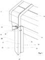
- the edge guide 20 of a curtain coating device is attached to the nozzle beam 10 of the curtain coating device.
- the coating color curtain is formed by nozzles of the nozzle beam 10 and guided via the nozzle lip 12 towards the fiber web.
- the width of the coating color curtain is controlled by edge guides 20, of which one is shown in figure 1 .
- the edge guide 20 is located below the edge strip 11 of the nozzle beam 10.
- the edge strip 11 guides the curtain to the edge guide 20.
- the edge guide 20 is connected to the nozzle beam 10 by a hinge 23, by which the inclination of the edge guide 20 in respect of vertical direction is controllable even during coating.
- the inclination is advantageously 1 - 3.
- a lubrication liquid feed 24 which feeds lubrication liquid between the edge guide 20 and the edge strip 11.
- the curtain edge is guided downwards by the flow surfaces 22 of the edge guide 20.
- the flow surfaces 22 form a flow guide recess 25 in the middle and the flow surfaces 22 with the flow guide recess 25 are in concave form.
- a protrusion 21 extending in the direction of the flow guide recess 25, which protrusion 21 guides the edge of the coating color curtain in the flow guide recess 25.
- the protrusion is advantageously shaped so that its form fits inside a half-circle, which has maximum radius 7,5 mm.
- Additional lubrication feeds 26 are located at a distance from the upper end of the edge guide providing lubrication liquid to both sides of the curtain edge in thickness direction of the curtain. At the lower end of the edge guide in the bottom corner is located suction opening 27 for removing excess lubrication liquid and for necking the curtain to the fiber web.
- FIG 2 is presented the upper part of the edge guide 20 of the example of figure 1 .
- the uppermost part of the edge guide 20 at the upper end of the edge guide has curved form with a radius R that corresponds to the center line of the hinge 23.
- the edge strip 11 connects to the upper end of the edge guide 20 smoothly.
- the lubrication liquid is fed by lubrication feed 24 from between the edge strip 11 and the upper end of the edge guide 20.
- the upper end of the edge guide 20 is either touching or located at a small distance, for example 0,5 - 2 mm, from the edge strip 11.
- a distance D for example 5 - 50 mm from the upper end of the edge guide 20 the additional lubrication feeds 26 are located.
- FIG 3 is presented the lower part of the edge guide 20 of the example of figures 1 and 2 .
- the curtain edge is guided downwards by the flow surfaces 22 of the edge guide 20.
- the flow surfaces 22 form a flow guide recess 25 in the middle and the flow surfaces 22 with the flow guide recess 25 are in concave form.
- suction opening 27 At the lower end of the edge guide 20 in the bottom corner is located suction opening 27 for removing excess lubrication liquid.
- FIG 4 is presented the flow surfaces 22 of the edge guide 20 of the example of figures 1 - 3 .
- the flow surfaces 22 form a flow guide recess 25 in the middle and the flow surfaces 22 with the flow guide recess 25 are in concave form.
- the flow surfaces 22 are inclined towards the middle and towards the flow guide recess 25 and the inclination angle A is advantageously 2 - 5 °.
- the middle of the flow surfaces 22 is formed the flow guide recess 25 with a protrusion 21.
- FIGS 5A - 5C is presented some examples of flow guide recess 25 with the protrusion 21 of the edge guide 20.
- the form of the protrusion 21 is outwards arched and in figures 5B and 5C angular.
- the protrusion 21 has an additional inwards arched groove 28.
- the cross section is shown at the location of the additional lubrication feeds 26, which are located on each side of the protrusion thus lubricating the curtain from each side in thickness direction.
- the flow surfaces 22 are inclined towards the middle and towards the flow guide recess 25 and the inclination angle A if each flow surface 22 is advantageously 2 - 5 °.
- the curtain coating device comprises a nozzle beam 10 with a nozzle lip 12 with an edge strip 11 for feeding the coating color curtain and edge guides 20, which are located along each edge of the feeding slot / the nozzle lip 12 to control the width of the curtain.
- the upper end of the edge guide 20 is at a small distance from the nozzle lip 12 of the nozzle beam 10.
- the edge strip 11 of the nozzle beam 10 is extended over the nozzle lip 12 of the nozzle beam 10, whereby the coating color flows over the edge strip 11 without disturbances.
- the edge strip 11 is connected to the edge guide 20 smoothly by a curved form. Lubrication liquid is fed to the connecting surface area by lubrication feed 24 from inside onto the surfaces 22.
- Additional lubrication liquid is fed from additional lubrication feeds 26 at a distance D from the upper end of the edge guide 20 downstream of the curtain on each side of the curtain in thickness direction of the curtain.
- the flow surfaces 22 with the flow guide recess 25 of the edge guide 20 are in its form concave towards the curtain.
- the edge guide 20 inclined from the vertical direction about 1 é to 3 é and the edge guide 20 has means for adjusting the inclination angle even during coating.
- the means for adjusting the inclination angle are advantageously the hinge 23 located near the upper end of the edge guide 20 and the center point of the radius R is on the center line of the hinge 23.
- the suction opening 27 for the lubrication liquid removal is located at the bottom corned of the edge guide at the curtain edge area.
- the suction opening 27 is one suction hole, which has circular cross section.
Landscapes
- Coating Apparatus (AREA)
- Paper (AREA)
Claims (12)
- Dispositif de revêtement à rideau pour machine à fibres, en particulier pour machine à papier et à carton, comprenant un faisceau de buses (10) doté d'une lèvre de buse (12) pourvue d'une bande périphérique (11) pour alimenter le rideau de couleur de revêtement et des guides périphériques (20) situés le long de chaque bord de la lèvre de buse (12) pour contrôler la largeur du rideau de couleur de revêtement, lequel guide périphérique (20) comprend une extrémité supérieure, une extrémité inférieure, des surfaces d'écoulement (22) s'étendant dans un sens substantiellement vertical parallèles et proches les uns des autres, une alimentation en lubrifiant (24), des alimentations supplémentaires en lubrifiant (26) et une ouverture d'aspiration (27), lesquelles surfaces d'écoulement (22) sont inclinées les unes vers les autres et forment un retrait de guide d'écoulement (25) s'étendant dans le sens vertical pour un guidage périphérique de rideau de manière à ce que la forme des surfaces d'écoulement (22) avec le retrait de guides d'écoulement (25) soit concave, laquelle alimentation en liquide lubrifiant (24) se trouve à la limite de la bande périphérique (11) et de l'extrémité supérieure du guide périphérique (20) entre la bande périphérique (11) et les surfaces d'écoulement (22) du guide périphérique (20), caractérisé en ce que, dans le retrait de guide d'écoulement (25), se trouve une saillie (21) s'étendant dans le sens du retrait de guide d'écoulement et que, à une distance (D) de l'extrémité supérieure du guide périphérique (20), en aval, se trouve au moins une alimentation supplémentaire en lubrifiant (26) sur un côté de la saillie (21).
- Dispositif de revêtement à rideau selon la revendication 1, caractérisé en ce que l'extrémité supérieure du guide périphérique (20) touche la lèvre de buse (12) du faisceau de buses (10).
- Dispositif de revêtement à rideau selon la revendication 1, caractérisé en ce que l'extrémité supérieure du guide périphérique (20) se trouve à une faible distance, par exemple 0,5 à 2 mm, de la lèvre de buse (12) du faisceau de buses (10).
- Dispositif de revêtement à rideau selon l'une quelconque des revendications 1 à 3, caractérisé en ce que, à une distance (D) de l'extrémité supérieure du guide périphérique (20), en aval, se trouvent des alimentations en lubrifiant supplémentaires (26) des deux côtés de la saillie (21).
- Dispositif de revêtement à rideau selon l'une quelconque des revendications 1 à 4, caractérisé en ce que le guide périphérique (20) est inclinable par rapport au sens vertical grâce à un moyen (23) réglage de l'angle d'inclinaison du guide périphérique (20).
- Dispositif de revêtement à rideau selon la revendication 5, caractérisé en ce que l'angle d'inclinaison du guide périphérique (20) est réglable pendant le revêtement.
- Dispositif de revêtement à rideau selon l'une quelconque des revendications 1 à 6, caractérisé en ce que la saillie (21) a une forme arquée.
- Dispositif de revêtement à rideau selon l'une quelconque des revendications 1 à 7, caractérisé en ce que l'ouverture d'aspiration (27) du guide périphérique (20) se trouve au point le plus bas de la partie inférieure du guide périphérique (20).
- Dispositif de revêtement à rideau selon l'une quelconque des revendications 1 à 8, caractérisé en ce que la bande périphérique (11) du faisceau de buses (10) s'étend au-dessus de la lèvre de buse (12) du faisceau de buses (10) et que la bande périphérique (11) est connectée au guide périphérique (20) de manière fluide par une forme courbée.
- Dispositif de revêtement à rideau selon l'une quelconque des revendications 4 à 6 ou 9, caractérisé en ce que le moyen de réglage de l'angle d'inclinaison est une charnière (23) située dans l'extrémité supérieure du guide périphérique (20) et que le point central du rayon (R) de la forme courbée dans la partie supérieure du guide périphérique (20) se trouve sur la ligne centrale de la charnière (23).
- Dispositif de revêtement à rideau selon la revendication 8, caractérisé en ce que l'ouverture d'aspiration (27) est un trou d'aspiration qui a une section transversale circulaire.
- Dispositif de revêtement à rideau selon l'une quelconque des revendications 1 à 11, caractérisé en ce que les surfaces d'écoulement (22) sont inclinées vers le retrait de guide d'écoulement (25) et que l'angle d'inclinaison (A) de chaque surface d'écoulement (22) est avantageusement de 2 à 5.
Priority Applications (3)
| Application Number | Priority Date | Filing Date | Title |
|---|---|---|---|
| EP14171250.5A EP2952264B1 (fr) | 2014-06-05 | 2014-06-05 | Dispositif de revêtement à rideau |
| CN201520368349.0U CN204825321U (zh) | 2014-06-05 | 2015-06-01 | 幕帘式涂布设备 |
| US14/729,781 US9675991B2 (en) | 2014-06-05 | 2015-06-03 | Curtain coating device |
Applications Claiming Priority (1)
| Application Number | Priority Date | Filing Date | Title |
|---|---|---|---|
| EP14171250.5A EP2952264B1 (fr) | 2014-06-05 | 2014-06-05 | Dispositif de revêtement à rideau |
Publications (2)
| Publication Number | Publication Date |
|---|---|
| EP2952264A1 EP2952264A1 (fr) | 2015-12-09 |
| EP2952264B1 true EP2952264B1 (fr) | 2019-10-30 |
Family
ID=50846870
Family Applications (1)
| Application Number | Title | Priority Date | Filing Date |
|---|---|---|---|
| EP14171250.5A Active EP2952264B1 (fr) | 2014-06-05 | 2014-06-05 | Dispositif de revêtement à rideau |
Country Status (3)
| Country | Link |
|---|---|
| US (1) | US9675991B2 (fr) |
| EP (1) | EP2952264B1 (fr) |
| CN (1) | CN204825321U (fr) |
Families Citing this family (1)
| Publication number | Priority date | Publication date | Assignee | Title |
|---|---|---|---|---|
| EP3342928A1 (fr) * | 2016-12-29 | 2018-07-04 | Valmet Technologies Oy | Dispositif d'application de rideau |
Family Cites Families (12)
| Publication number | Priority date | Publication date | Assignee | Title |
|---|---|---|---|---|
| DE3300150A1 (de) * | 1983-01-04 | 1984-07-05 | Agfa-Gevaert Ag, 5090 Leverkusen | Verfahren und vorrichtung zur stabilisierung von frei fallenden fluessigkeitsvorhaengen |
| US5382292A (en) * | 1993-07-28 | 1995-01-17 | Eastman Kodak Company | Edge guide lubricating fluid delivery apparatus |
| WO2003049870A1 (fr) | 2001-12-13 | 2003-06-19 | Dow Global Technologies Inc. | Procede et dispositif d'enduction au rideau |
| ATE354443T1 (de) | 2002-09-10 | 2007-03-15 | Ilford Imaging Ch Gmbh | Verfahren und vorrichtung zur vorhangbeschichtung eines bewegten trägers |
| DE102004016923B4 (de) * | 2004-04-06 | 2006-08-03 | Polytype Converting S.A. | Vorhangbeschichter und Vorhangbeschichtungsverfahren |
| DE102004056270A1 (de) | 2004-11-22 | 2006-05-24 | Basf Ag | Seitenführung für die Vorhangbeschichtung |
| DE102006030183A1 (de) * | 2006-06-30 | 2008-01-03 | Polytype Converting S.A. | Vorhangbeschichter mit poröser Vorhangführungsstruktur, Vorhangführungsstruktur für einen Vorhangbeschichter und Verfahren zur Herstellung der Vorhangführungsstruktur |
| US7870833B2 (en) | 2006-09-15 | 2011-01-18 | Ricoh Company, Ltd. | Slide curtain coating apparatus and slide curtain coating method |
| FI119740B (fi) | 2007-12-11 | 2009-02-27 | Metso Paper Inc | Järjestely ja menetelmä tasolta syöttävän verhopäällystimen applikointileveyden säätämiseksi |
| DE102009000809A1 (de) * | 2009-02-12 | 2010-08-19 | Voith Patent Gmbh | Vorhang-Auftragswerk |
| JP2011050816A (ja) * | 2009-08-31 | 2011-03-17 | Voith Patent Gmbh | カーテンコータのエッジガイド |
| EP2292336B1 (fr) * | 2009-09-08 | 2014-08-13 | Ricoh Company, Ltd. | Dispositif d'enduction à rideau et procédé d'enduction à rideau |
-
2014
- 2014-06-05 EP EP14171250.5A patent/EP2952264B1/fr active Active
-
2015
- 2015-06-01 CN CN201520368349.0U patent/CN204825321U/zh not_active Expired - Lifetime
- 2015-06-03 US US14/729,781 patent/US9675991B2/en not_active Expired - Fee Related
Non-Patent Citations (1)
| Title |
|---|
| None * |
Also Published As
| Publication number | Publication date |
|---|---|
| US20150352590A1 (en) | 2015-12-10 |
| CN204825321U (zh) | 2015-12-02 |
| EP2952264A1 (fr) | 2015-12-09 |
| US9675991B2 (en) | 2017-06-13 |
Similar Documents
| Publication | Publication Date | Title |
|---|---|---|
| US4479987A (en) | Process and an apparatus for stabilizing free-falling liquid curtains | |
| CA1331113C (fr) | Methode de couchage par voile, et appareil connexe | |
| US20080029024A1 (en) | Applicator | |
| EP1857189B1 (fr) | Appareil d' application et procede pour la fabrication d' une toile avec pellicule de revetement | |
| CN101103155B (zh) | 用于调节滑动喂料幕帘式涂布机的施涂宽度的装置 | |
| CN102497936A (zh) | 幕帘涂布机的边缘引导件 | |
| US20070137563A1 (en) | Curtain coater and curtain coating method | |
| EP0651095A1 (fr) | Procédé et dispositif pour enduire une bande en mouvement | |
| JP4744538B2 (ja) | 紙/板紙ウェブのためのカーテンコーティング装置 | |
| GB2227959A (en) | Blade coating a material web | |
| US9675991B2 (en) | Curtain coating device | |
| EP0512971A1 (fr) | Procédé et dispositif de revêtement d'un substrat mobile | |
| US7081163B2 (en) | Edge-control system for curtain coater | |
| FI119444B (fi) | Paperi-/kartonkirainan päällystyslaite | |
| US5976251A (en) | Inlet for introducing water to wire edge guides for curtain coating | |
| EP2894254B1 (fr) | Dispositif de revêtement pour l'application de couleur de revêtement sur une bande de fibres et procédé associé | |
| JP5228226B2 (ja) | 感熱紙の製造装置 | |
| EP3342928A1 (fr) | Dispositif d'application de rideau | |
| JP7245047B2 (ja) | カーテンコータ | |
| JP7732659B2 (ja) | 液体またはスラリーの塗布装置および塗装金属帯の製造方法 | |
| EP1838456A1 (fr) | Procede pour enlever un « talus » de bordure forme au niveau de la bordure d'une bande couchee par couchage par voile effectue sous forme de couchage de bordure a sec | |
| JP3137217U (ja) | 平面から供給するカーテンコーティング装置の塗工幅の調節装置 | |
| EP1841917B1 (fr) | Dispositif de support utilise dans le couchage par voile d'une bande de papier/carton | |
| JP2000157916A (ja) | 走行中の基面に液状またはペ―スト状の塗被媒体を塗被するための塗被装置および塗被方法 | |
| JP2014076432A (ja) | カーテン塗布装置 |
Legal Events
| Date | Code | Title | Description |
|---|---|---|---|
| PUAI | Public reference made under article 153(3) epc to a published international application that has entered the european phase |
Free format text: ORIGINAL CODE: 0009012 |
|
| AK | Designated contracting states |
Kind code of ref document: A1 Designated state(s): AL AT BE BG CH CY CZ DE DK EE ES FI FR GB GR HR HU IE IS IT LI LT LU LV MC MK MT NL NO PL PT RO RS SE SI SK SM TR |
|
| AX | Request for extension of the european patent |
Extension state: BA ME |
|
| 17P | Request for examination filed |
Effective date: 20160502 |
|
| RBV | Designated contracting states (corrected) |
Designated state(s): AL AT BE BG CH CY CZ DE DK EE ES FI FR GB GR HR HU IE IS IT LI LT LU LV MC MK MT NL NO PL PT RO RS SE SI SK SM TR |
|
| STAA | Information on the status of an ep patent application or granted ep patent |
Free format text: STATUS: EXAMINATION IS IN PROGRESS |
|
| 17Q | First examination report despatched |
Effective date: 20190102 |
|
| GRAP | Despatch of communication of intention to grant a patent |
Free format text: ORIGINAL CODE: EPIDOSNIGR1 |
|
| STAA | Information on the status of an ep patent application or granted ep patent |
Free format text: STATUS: GRANT OF PATENT IS INTENDED |
|
| INTG | Intention to grant announced |
Effective date: 20190603 |
|
| GRAS | Grant fee paid |
Free format text: ORIGINAL CODE: EPIDOSNIGR3 |
|
| GRAA | (expected) grant |
Free format text: ORIGINAL CODE: 0009210 |
|
| STAA | Information on the status of an ep patent application or granted ep patent |
Free format text: STATUS: THE PATENT HAS BEEN GRANTED |
|
| AK | Designated contracting states |
Kind code of ref document: B1 Designated state(s): AL AT BE BG CH CY CZ DE DK EE ES FI FR GB GR HR HU IE IS IT LI LT LU LV MC MK MT NL NO PL PT RO RS SE SI SK SM TR |
|
| REG | Reference to a national code |
Ref country code: GB Ref legal event code: FG4D |
|
| REG | Reference to a national code |
Ref country code: CH Ref legal event code: EP |
|
| REG | Reference to a national code |
Ref country code: AT Ref legal event code: REF Ref document number: 1195576 Country of ref document: AT Kind code of ref document: T Effective date: 20191115 |
|
| REG | Reference to a national code |
Ref country code: DE Ref legal event code: R096 Ref document number: 602014055839 Country of ref document: DE |
|
| REG | Reference to a national code |
Ref country code: IE Ref legal event code: FG4D |
|
| REG | Reference to a national code |
Ref country code: LT Ref legal event code: MG4D |
|
| PG25 | Lapsed in a contracting state [announced via postgrant information from national office to epo] |
Ref country code: NL Free format text: LAPSE BECAUSE OF FAILURE TO SUBMIT A TRANSLATION OF THE DESCRIPTION OR TO PAY THE FEE WITHIN THE PRESCRIBED TIME-LIMIT Effective date: 20191030 Ref country code: LV Free format text: LAPSE BECAUSE OF FAILURE TO SUBMIT A TRANSLATION OF THE DESCRIPTION OR TO PAY THE FEE WITHIN THE PRESCRIBED TIME-LIMIT Effective date: 20191030 Ref country code: SE Free format text: LAPSE BECAUSE OF FAILURE TO SUBMIT A TRANSLATION OF THE DESCRIPTION OR TO PAY THE FEE WITHIN THE PRESCRIBED TIME-LIMIT Effective date: 20191030 Ref country code: BG Free format text: LAPSE BECAUSE OF FAILURE TO SUBMIT A TRANSLATION OF THE DESCRIPTION OR TO PAY THE FEE WITHIN THE PRESCRIBED TIME-LIMIT Effective date: 20200130 Ref country code: FI Free format text: LAPSE BECAUSE OF FAILURE TO SUBMIT A TRANSLATION OF THE DESCRIPTION OR TO PAY THE FEE WITHIN THE PRESCRIBED TIME-LIMIT Effective date: 20191030 Ref country code: PT Free format text: LAPSE BECAUSE OF FAILURE TO SUBMIT A TRANSLATION OF THE DESCRIPTION OR TO PAY THE FEE WITHIN THE PRESCRIBED TIME-LIMIT Effective date: 20200302 Ref country code: NO Free format text: LAPSE BECAUSE OF FAILURE TO SUBMIT A TRANSLATION OF THE DESCRIPTION OR TO PAY THE FEE WITHIN THE PRESCRIBED TIME-LIMIT Effective date: 20200130 Ref country code: GR Free format text: LAPSE BECAUSE OF FAILURE TO SUBMIT A TRANSLATION OF THE DESCRIPTION OR TO PAY THE FEE WITHIN THE PRESCRIBED TIME-LIMIT Effective date: 20200131 Ref country code: ES Free format text: LAPSE BECAUSE OF FAILURE TO SUBMIT A TRANSLATION OF THE DESCRIPTION OR TO PAY THE FEE WITHIN THE PRESCRIBED TIME-LIMIT Effective date: 20191030 Ref country code: LT Free format text: LAPSE BECAUSE OF FAILURE TO SUBMIT A TRANSLATION OF THE DESCRIPTION OR TO PAY THE FEE WITHIN THE PRESCRIBED TIME-LIMIT Effective date: 20191030 Ref country code: PL Free format text: LAPSE BECAUSE OF FAILURE TO SUBMIT A TRANSLATION OF THE DESCRIPTION OR TO PAY THE FEE WITHIN THE PRESCRIBED TIME-LIMIT Effective date: 20191030 |
|
| REG | Reference to a national code |
Ref country code: NL Ref legal event code: MP Effective date: 20191030 |
|
| PG25 | Lapsed in a contracting state [announced via postgrant information from national office to epo] |
Ref country code: HR Free format text: LAPSE BECAUSE OF FAILURE TO SUBMIT A TRANSLATION OF THE DESCRIPTION OR TO PAY THE FEE WITHIN THE PRESCRIBED TIME-LIMIT Effective date: 20191030 Ref country code: IS Free format text: LAPSE BECAUSE OF FAILURE TO SUBMIT A TRANSLATION OF THE DESCRIPTION OR TO PAY THE FEE WITHIN THE PRESCRIBED TIME-LIMIT Effective date: 20200229 Ref country code: RS Free format text: LAPSE BECAUSE OF FAILURE TO SUBMIT A TRANSLATION OF THE DESCRIPTION OR TO PAY THE FEE WITHIN THE PRESCRIBED TIME-LIMIT Effective date: 20191030 |
|
| PG25 | Lapsed in a contracting state [announced via postgrant information from national office to epo] |
Ref country code: AL Free format text: LAPSE BECAUSE OF FAILURE TO SUBMIT A TRANSLATION OF THE DESCRIPTION OR TO PAY THE FEE WITHIN THE PRESCRIBED TIME-LIMIT Effective date: 20191030 |
|
| PG25 | Lapsed in a contracting state [announced via postgrant information from national office to epo] |
Ref country code: CZ Free format text: LAPSE BECAUSE OF FAILURE TO SUBMIT A TRANSLATION OF THE DESCRIPTION OR TO PAY THE FEE WITHIN THE PRESCRIBED TIME-LIMIT Effective date: 20191030 Ref country code: RO Free format text: LAPSE BECAUSE OF FAILURE TO SUBMIT A TRANSLATION OF THE DESCRIPTION OR TO PAY THE FEE WITHIN THE PRESCRIBED TIME-LIMIT Effective date: 20191030 Ref country code: DK Free format text: LAPSE BECAUSE OF FAILURE TO SUBMIT A TRANSLATION OF THE DESCRIPTION OR TO PAY THE FEE WITHIN THE PRESCRIBED TIME-LIMIT Effective date: 20191030 Ref country code: EE Free format text: LAPSE BECAUSE OF FAILURE TO SUBMIT A TRANSLATION OF THE DESCRIPTION OR TO PAY THE FEE WITHIN THE PRESCRIBED TIME-LIMIT Effective date: 20191030 |
|
| REG | Reference to a national code |
Ref country code: DE Ref legal event code: R097 Ref document number: 602014055839 Country of ref document: DE |
|
| PG25 | Lapsed in a contracting state [announced via postgrant information from national office to epo] |
Ref country code: IT Free format text: LAPSE BECAUSE OF FAILURE TO SUBMIT A TRANSLATION OF THE DESCRIPTION OR TO PAY THE FEE WITHIN THE PRESCRIBED TIME-LIMIT Effective date: 20191030 Ref country code: SK Free format text: LAPSE BECAUSE OF FAILURE TO SUBMIT A TRANSLATION OF THE DESCRIPTION OR TO PAY THE FEE WITHIN THE PRESCRIBED TIME-LIMIT Effective date: 20191030 Ref country code: SM Free format text: LAPSE BECAUSE OF FAILURE TO SUBMIT A TRANSLATION OF THE DESCRIPTION OR TO PAY THE FEE WITHIN THE PRESCRIBED TIME-LIMIT Effective date: 20191030 |
|
| PLBE | No opposition filed within time limit |
Free format text: ORIGINAL CODE: 0009261 |
|
| STAA | Information on the status of an ep patent application or granted ep patent |
Free format text: STATUS: NO OPPOSITION FILED WITHIN TIME LIMIT |
|
| 26N | No opposition filed |
Effective date: 20200731 |
|
| PG25 | Lapsed in a contracting state [announced via postgrant information from national office to epo] |
Ref country code: SI Free format text: LAPSE BECAUSE OF FAILURE TO SUBMIT A TRANSLATION OF THE DESCRIPTION OR TO PAY THE FEE WITHIN THE PRESCRIBED TIME-LIMIT Effective date: 20191030 |
|
| PG25 | Lapsed in a contracting state [announced via postgrant information from national office to epo] |
Ref country code: MC Free format text: LAPSE BECAUSE OF FAILURE TO SUBMIT A TRANSLATION OF THE DESCRIPTION OR TO PAY THE FEE WITHIN THE PRESCRIBED TIME-LIMIT Effective date: 20191030 |
|
| GBPC | Gb: european patent ceased through non-payment of renewal fee |
Effective date: 20200605 |
|
| PG25 | Lapsed in a contracting state [announced via postgrant information from national office to epo] |
Ref country code: LU Free format text: LAPSE BECAUSE OF NON-PAYMENT OF DUE FEES Effective date: 20200605 |
|
| REG | Reference to a national code |
Ref country code: BE Ref legal event code: MM Effective date: 20200630 |
|
| PG25 | Lapsed in a contracting state [announced via postgrant information from national office to epo] |
Ref country code: GB Free format text: LAPSE BECAUSE OF NON-PAYMENT OF DUE FEES Effective date: 20200605 Ref country code: IE Free format text: LAPSE BECAUSE OF NON-PAYMENT OF DUE FEES Effective date: 20200605 Ref country code: FR Free format text: LAPSE BECAUSE OF NON-PAYMENT OF DUE FEES Effective date: 20200630 |
|
| PG25 | Lapsed in a contracting state [announced via postgrant information from national office to epo] |
Ref country code: BE Free format text: LAPSE BECAUSE OF NON-PAYMENT OF DUE FEES Effective date: 20200630 |
|
| REG | Reference to a national code |
Ref country code: AT Ref legal event code: UEP Ref document number: 1195576 Country of ref document: AT Kind code of ref document: T Effective date: 20191030 |
|
| PG25 | Lapsed in a contracting state [announced via postgrant information from national office to epo] |
Ref country code: TR Free format text: LAPSE BECAUSE OF FAILURE TO SUBMIT A TRANSLATION OF THE DESCRIPTION OR TO PAY THE FEE WITHIN THE PRESCRIBED TIME-LIMIT Effective date: 20191030 Ref country code: MT Free format text: LAPSE BECAUSE OF FAILURE TO SUBMIT A TRANSLATION OF THE DESCRIPTION OR TO PAY THE FEE WITHIN THE PRESCRIBED TIME-LIMIT Effective date: 20191030 Ref country code: CY Free format text: LAPSE BECAUSE OF FAILURE TO SUBMIT A TRANSLATION OF THE DESCRIPTION OR TO PAY THE FEE WITHIN THE PRESCRIBED TIME-LIMIT Effective date: 20191030 |
|
| PG25 | Lapsed in a contracting state [announced via postgrant information from national office to epo] |
Ref country code: MK Free format text: LAPSE BECAUSE OF FAILURE TO SUBMIT A TRANSLATION OF THE DESCRIPTION OR TO PAY THE FEE WITHIN THE PRESCRIBED TIME-LIMIT Effective date: 20191030 |
|
| PGFP | Annual fee paid to national office [announced via postgrant information from national office to epo] |
Ref country code: DE Payment date: 20250618 Year of fee payment: 12 |
|
| PGFP | Annual fee paid to national office [announced via postgrant information from national office to epo] |
Ref country code: AT Payment date: 20250620 Year of fee payment: 12 |
|
| PGFP | Annual fee paid to national office [announced via postgrant information from national office to epo] |
Ref country code: CH Payment date: 20250701 Year of fee payment: 12 |