EP2952290A1 - Traîneau pour déplacer linéaire d'un dispositif - Google Patents
Traîneau pour déplacer linéaire d'un dispositif Download PDFInfo
- Publication number
- EP2952290A1 EP2952290A1 EP15001650.9A EP15001650A EP2952290A1 EP 2952290 A1 EP2952290 A1 EP 2952290A1 EP 15001650 A EP15001650 A EP 15001650A EP 2952290 A1 EP2952290 A1 EP 2952290A1
- Authority
- EP
- European Patent Office
- Prior art keywords
- rod
- rack
- switch
- cylinder
- fluid
- Prior art date
- Legal status (The legal status is an assumption and is not a legal conclusion. Google has not performed a legal analysis and makes no representation as to the accuracy of the status listed.)
- Granted
Links
Images


Classifications
-
- B—PERFORMING OPERATIONS; TRANSPORTING
- B23—MACHINE TOOLS; METAL-WORKING NOT OTHERWISE PROVIDED FOR
- B23Q—DETAILS, COMPONENTS, OR ACCESSORIES FOR MACHINE TOOLS, e.g. ARRANGEMENTS FOR COPYING OR CONTROLLING; MACHINE TOOLS IN GENERAL CHARACTERISED BY THE CONSTRUCTION OF PARTICULAR DETAILS OR COMPONENTS; COMBINATIONS OR ASSOCIATIONS OF METAL-WORKING MACHINES, NOT DIRECTED TO A PARTICULAR RESULT
- B23Q5/00—Driving or feeding mechanisms; Control arrangements therefor
- B23Q5/22—Feeding members carrying tools or work
- B23Q5/34—Feeding other members supporting tools or work, e.g. saddles, tool-slides, through mechanical transmission
-
- B—PERFORMING OPERATIONS; TRANSPORTING
- B23—MACHINE TOOLS; METAL-WORKING NOT OTHERWISE PROVIDED FOR
- B23Q—DETAILS, COMPONENTS, OR ACCESSORIES FOR MACHINE TOOLS, e.g. ARRANGEMENTS FOR COPYING OR CONTROLLING; MACHINE TOOLS IN GENERAL CHARACTERISED BY THE CONSTRUCTION OF PARTICULAR DETAILS OR COMPONENTS; COMBINATIONS OR ASSOCIATIONS OF METAL-WORKING MACHINES, NOT DIRECTED TO A PARTICULAR RESULT
- B23Q16/00—Equipment for precise positioning of tool or work into particular locations not otherwise provided for
- B23Q16/001—Stops, cams, or holders therefor
-
- B—PERFORMING OPERATIONS; TRANSPORTING
- B23—MACHINE TOOLS; METAL-WORKING NOT OTHERWISE PROVIDED FOR
- B23Q—DETAILS, COMPONENTS, OR ACCESSORIES FOR MACHINE TOOLS, e.g. ARRANGEMENTS FOR COPYING OR CONTROLLING; MACHINE TOOLS IN GENERAL CHARACTERISED BY THE CONSTRUCTION OF PARTICULAR DETAILS OR COMPONENTS; COMBINATIONS OR ASSOCIATIONS OF METAL-WORKING MACHINES, NOT DIRECTED TO A PARTICULAR RESULT
- B23Q16/00—Equipment for precise positioning of tool or work into particular locations not otherwise provided for
- B23Q16/02—Indexing equipment
- B23Q16/08—Indexing equipment having means for clamping the relatively movable parts together in the indexed position
- B23Q16/083—Indexing equipment having means for clamping the relatively movable parts together in the indexed position with a reciprocating or oscillating drive
-
- B—PERFORMING OPERATIONS; TRANSPORTING
- B23—MACHINE TOOLS; METAL-WORKING NOT OTHERWISE PROVIDED FOR
- B23Q—DETAILS, COMPONENTS, OR ACCESSORIES FOR MACHINE TOOLS, e.g. ARRANGEMENTS FOR COPYING OR CONTROLLING; MACHINE TOOLS IN GENERAL CHARACTERISED BY THE CONSTRUCTION OF PARTICULAR DETAILS OR COMPONENTS; COMBINATIONS OR ASSOCIATIONS OF METAL-WORKING MACHINES, NOT DIRECTED TO A PARTICULAR RESULT
- B23Q17/00—Arrangements for observing, indicating or measuring on machine tools
-
- B—PERFORMING OPERATIONS; TRANSPORTING
- B23—MACHINE TOOLS; METAL-WORKING NOT OTHERWISE PROVIDED FOR
- B23Q—DETAILS, COMPONENTS, OR ACCESSORIES FOR MACHINE TOOLS, e.g. ARRANGEMENTS FOR COPYING OR CONTROLLING; MACHINE TOOLS IN GENERAL CHARACTERISED BY THE CONSTRUCTION OF PARTICULAR DETAILS OR COMPONENTS; COMBINATIONS OR ASSOCIATIONS OF METAL-WORKING MACHINES, NOT DIRECTED TO A PARTICULAR RESULT
- B23Q5/00—Driving or feeding mechanisms; Control arrangements therefor
- B23Q5/22—Feeding members carrying tools or work
- B23Q5/34—Feeding other members supporting tools or work, e.g. saddles, tool-slides, through mechanical transmission
- B23Q5/38—Feeding other members supporting tools or work, e.g. saddles, tool-slides, through mechanical transmission feeding continuously
- B23Q5/385—Feeding other members supporting tools or work, e.g. saddles, tool-slides, through mechanical transmission feeding continuously using a gear and rack mechanism or a friction wheel co-operating with a rail
-
- B—PERFORMING OPERATIONS; TRANSPORTING
- B23—MACHINE TOOLS; METAL-WORKING NOT OTHERWISE PROVIDED FOR
- B23Q—DETAILS, COMPONENTS, OR ACCESSORIES FOR MACHINE TOOLS, e.g. ARRANGEMENTS FOR COPYING OR CONTROLLING; MACHINE TOOLS IN GENERAL CHARACTERISED BY THE CONSTRUCTION OF PARTICULAR DETAILS OR COMPONENTS; COMBINATIONS OR ASSOCIATIONS OF METAL-WORKING MACHINES, NOT DIRECTED TO A PARTICULAR RESULT
- B23Q5/00—Driving or feeding mechanisms; Control arrangements therefor
- B23Q5/22—Feeding members carrying tools or work
- B23Q5/52—Limiting feed movement
Definitions
- the present invention relates generally to devices adapted to move a working equipment, in particular in the context of machines used, for example, for manufacturing motor vehicle body parts.
- the invention relates to a device of the type mentioned in the preamble of appended claim 1.
- a stopping unit allows the cylinder rod to be locked, for example when it reaches one end-of-stroke position, or when a pressure drop below a predetermined threshold occurs in the feeding system.
- these devices are designed to move a specific equipment in the context of a determined working plant and, therefore, they have a fixed size that corresponds to that required for their use.
- the known linear moving devices are not much flexible since they cannot be easily adapted to different requirements of use, for example to be used in other working plants different from those for which they have been originally designed.
- the stopping units of these known devices are usually low accurate and low reliable because the locking members of the rod of the control cylinder, which usually consists of rollers or balls adapted to apply a frictional force on the outer surface of the rod, do not allow an instantaneous stopping of the cylinder rod to be obtained, also owing to the fact that their accuracy is affected by wearing of their components, which can be a source of problems.
- the main object of the present invention is to propose a sled device for linearly moving an equipment, the structure of which can be modified in a simple manner to be fitted to different use conditions, for example to allow it to be used in different working plants.
- the device includes detection means for detecting reaching of a first end-of-stroke position by a portion of the rod, which detection means comprise at least a first switch mounted on a base element and connected with a line for feeding the fluid to the main cylinder, which switch is operable by said portion of the rod to substantially stop feeding of the fluid to the main cylinder and to automatically activate the stopping means, said first switch being fixable on the base element by adjustable positioning means so as to allow the first end-of-stroke position of the of the rod to be adjusted with respect to said cylinder in order to change the operational size of the device.
- detection means comprise at least a first switch mounted on a base element and connected with a line for feeding the fluid to the main cylinder, which switch is operable by said portion of the rod to substantially stop feeding of the fluid to the main cylinder and to automatically activate the stopping means, said first switch being fixable on the base element by adjustable positioning means so as to allow the first end-of-stroke position of the of the rod to be adjusted with respect to said cylinder in order to change the operational size of the
- the device according to the invention has a flexible structure that can be adapted simply and quickly to allow the device to be associated with different working plants, or to be adapted to different working conditions.
- the adjustable positioning means comprise fastening means associated with a support body for supporting the first switch, which are adapted to engage corresponding formations of the base element in one of a plurality of positions.
- the adjustable positioning means of the first switch have a simple and reliable structure, inexpensive to be manufactured.
- the adjustable positioning means comprise spacing means of a calibrated thickness, adapted to be interposed between the first switch and said support body.
- the structure of the device can be adjusted to be adapted precisely to the operational size of different working plants.
- the detection means comprise a second switch operable as a result of reaching by the rod of a second end-of-stroke position, opposite to said first end-of-stroke position, which is adapted to substantially stop feeding of said fluid to the main cylinder when the rod reaches said second end-of-stroke position.
- the device allows displacement of the rod to be effectively locked in both its opposite end-of-stroke positions.
- said stopping means for stopping the rod comprise at least one first and at least one second mutually engageable shaped formations, preferably consisting of a first rack and of a second rack, one of which is slidably associated with the cylinder, and the other of which is connected to the rod of the cylinder.
- the structure of the device according to the invention is relatively simple and compact and highly reliable in the use and, in particular, it allows an automatic and immediate stop of the rod to be got at its opposite end-of-stroke positions, and also in any possible intermediate position, for example when an anomaly in the feeding system of the pressurized fluid occurs.
- 10 indicates as a whole a sled device according to the invention, which is intended to move an equipment (not shown in the figures), adapted, for example, to perform one or more machining on workpieces in a production line, between a pair of spaced-apart positions, typically an operative position and a resting position.
- the device 10 comprises a base plate 12, for example having a rectangular shape, to which a control assembly is connected that includes essentially a cylinder 14 of a type known per se, usually of the pneumatic double-acting or single-acting type, fixed at one side of the plate 12.
- a pressurized gas typically compressed air, is fed to the cylinder 14 for controlling the axial sliding of a rod 20 between a pair of opposite end-of-stroke positions.
- the body of the cylinder 14 is fixed to a box-shaped body 16, fixed in turn to the plate 12, a through hole 18 being formed in the body 16, within which the rod 20 is slidably engaged, so that the linear movement of the rod 20 is guided by the hole 18 of the body 16.
- the rod 20 has an end 22 that projects outside the body 16, on which a buffer 24 is applied.
- This buffer 24 as a result of the axial movement of the rod 20, can reach a number of possible positions each of which may corresponds to a possible extended end-of-stroke configuration of the rod 20.
- the buffer 24 is intended to engage in frontal contact a first switch 26 fixed to the base plate 12 by a substantially T-shaped support 27 having a branch 27a that extends transversely to the plate 12.
- the pitch of the smooth holes 28a and of the threaded holes 29a is 10 mm, and axial rows of holes 28a and 29a can be formed in the plate 12, each of which comprises, for example, six of such holes.
- the legs 28 and the screws 29, as well as the respective holes 28a and 29a can be replaced by different adjustable positioning means of a type known per se, having an equivalent function.
- One or more preferably U-shaped spacer elements 25 ( Figures 6 and 7 ) having a calibrated thickness, can be interposed between the transverse branch 27a of the support 27 and a head collar of the switch 26, which has for example a hexagonal shape, in order to allow the relative position of the switch 26 to be finely adjusted with respect to the support 27.
- spacer elements 25 of a variable thickness from 1 to 3 mm, can be used, depending on the need.
- the position of the switch 26 can be adjusted in two different modes, in order to change the relative end-of-stroke position of the rod 20 and, therefore, to adjust the operational size of the device 10.
- the support 27 can be connected to the plate 12 in one of a plurality of possible axial positions (two of which are shown by continuous lines and by broken lines, respectively, in Figure 6 ) with respect to the cylinder 14.
- the support 27 can be mounted in an axial position, with respect to the cylinder 14, which is defined by a set of holes 28a and 29a of the plate 12, by the engagement of the legs 28 and of the screws 29 thereof into them.
- the support 27, and therefore the switch 26 can be moved of a maximum length of 60 mm with respect to the position thereof that corresponds to the maximum extension of the rod 20.
- one or more spacer elements 25 can be interposed between the head collar of the switch 26 and the branch 27a of the support 27, so as to finely adjust the axial position of the switch 26 with respect to the support 27, and therefore with respect to the cylinder 14.
- a T-shaped bracket 30 is connected to the rod 20 in proximity of its end 22, a mobile platform 32, consisting for example of a rectangular plate, being fastened to such a bracket.
- the platform 32 is conveniently provided with connecting holes to allow the aforesaid equipment to be fastened, whereby the platform 32 and the equipment brought on it are fast to the rod 20.
- a pair of rails 34 extending along directions parallel to the rod 20 are connected to the base plate 12, side by side to the rod 20, on each of which a respective trolley 36 is slidably mounted, which is fastened to the platform 32.
- a second switch 38 is fixed to the base plate 12 through an angular support 40, so that the trolley 36 slidable on this rail 34 can reach a condition of contact with the switch 38 when the rod 20 is in its fully retracted configuration with respect to the cylinder 14, which corresponds to the other end-of-stroke position of the rod 20.
- Both the switches 26 and 38 are connected with a feeding line for feeding the fluid to the main cylinder 14, and they are conveniently made by micro-switches of the electro-mechanical type. In particular, they constitute detection means for detecting the reaching of the respective end-of-stroke positions by the rod 20.
- the switches 26 and 38 are switched to interrupt feeding of fluid to the cylinder 14, or to cause, at any rate, a reduction of its pressure below a predetermined threshold, as it will be explained below.
- the rail 34 arranged at the side opposite to that associated with the switch 38 preferably supports a damping unit 42 at its end opposite to the cylinder 14, for dampening the force of impact of the respective trolley 36, and therefore of the platform 32, when the rod 20 reaches its configuration of maximum extension with respect to the cylinder 14.
- the device 10 also includes a stopping unit serving to lock automatically and instantaneously the movement of the rod 20 with respect to the cylinder 14, for example at its opposite end-of-stroke positions, by effect of the switching of the switches 26 and 38.
- This stopping unit comprises at least two mutually engageable shaped formations, one of which is slidably associated with respect to the base plate 12, and therefore with respect to the cylinder 14, while the other is connected to the rod 20.
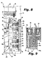
- these shaped formations consist of a pair of opposite racks 44, equal to each other, which are fitted to the shaft 20 at a position adjacent to the bracket 30 in such a manner to extend along a direction parallel to the rod 20, with their teeth 44a facing radially outside the rod 20, and another pair of opposite racks 46, also equal to each other, which teeth 46a face the racks 44, and therefore the rod 20.
- the axial length of the racks 44 is substantially less than that of the racks 46.
- each rack 46 is connected to the plate 12 by a respective axial holding element 48, so that the racks 46 are slidably mounted radially to the rod 20, with a possibility of relative movement with respect to the rod.
- a respective cover plate 50 is superimposed to each rack 46, into contact with the upper face of the latter and connected to it through the holding elements 48 thereof, with a possibility of relative sliding, whereby the plate 50 constitutes a guide for the radial sliding movement of the respective rack 46 according a to-and-fro movement with respect to the rod 20.
- actuating means are operatively interposed between each rack 46 and a respective support wall 54 fixed perpendicular to the plate 12, and therefore fast to the cylinder 14.
- actuating means include, for each rack 46, at least one control actuator 56, and preferably a pair of control actuators 56 each of which is arranged close to an axial end of the respective rack 46.
- Each actuator 56 comprises a chamber 58 in which an auxiliary piston 60 is sealingly and slidably mounted, and from which a stem 62 extends, which is connected to the respective rack 46.
- the same pressurized fluid that is fed also to the cylinder 14, is fed into the chamber 58 from the side of the piston 60 facing the rack 46, while elastic thrust means, resting against a member connected to the respective wall 54, are arranged at the opposite side of the piston 60, these elastic means being preferably made by a pack of Belleville springs 64.
- the springs 64 allow a thrust to be applied on the piston 60 and therefore, through it, on the respective rack 46, with the aim of bringing the rack 46 into its frontal engagement condition with the respective rack 44.
- the load of the springs 64 is calculated so as the racks 46 can assume a position at least slightly spaced from the racks 44 when the pressure of the fluid fed to the chambers 58 of the actuators 56 exceeds a predetermined threshold.
- the actuators 56 cause the movement of the racks 46 to the engagement of the racks 44, in order to lock instantaneously, with a high accuracy, the sliding of the rod 20.
- a load applied to the platform 32 from the equipment cannot cause the platform 32 to move further in the axial direction of the rod 20.
- this stopping condition of the rod 20 takes place when the switches 26 or 38 detect the contact with the buffer 24 of the rod 20, or with one of the trolleys 36, in the two opposite end-of-stroke positions of the rod 20, respectively.
- the movement of the rod 20 is stopped in the event of an interruption of the pressure of the fluid fed to the cylinder 14, or of a pressure drop thereof below the aforesaid predetermined threshold, and consequently in the chambers 58 of the actuators 56, which may occur owing to a malfunction in any position of the rod 20 between its end-of-stroke positions.
- a plate 67 is fixed on the face of each rack 46 facing the respective wall 54, and therefore on the side opposite to the teeth 46a, from which plate a transverse pin 68 extends.
- the contact of the pin 68 with the wall 54 generates a signal detectable by a micro-switch 70, preferably of the inductive type, carried by the respective wall 54, to signal the movement of the respective rack 46 towards its disengagement position, therefore spaced, with respect to the respective rack 44.
- the micro-switches 70 are provided with visual signaling means, typically of the LED light type, for signaling actuation of the actuators 56.
- the teeth 44a of both the racks 44 are aligned with each other in the axial direction of the rod 20, while the teeth 46a of each of the racks 46 are offset to each other by half a pitch in the axial direction of the rod 20.
- This allows the rod 20 to be locked very quickly by virtue of the fact that locking of the stroke of the rod 20 takes place in one of a series of positions very close together, the interval of which corresponds to half a pitch between the teeth 44a and 46a. For example, for a pitch of 2 mm of the teeth of the racks 44 and 46, locking of the rod 20 caused by the stopping means can take place with intervals of 1 mm.
- the teeth 44a of the two racks 44 may be arranged mutually offset by half a pitch in the axial direction of the rod 20, while the teeth 46a of the racks 46 are aligned with each other in the axial direction of the rod 20.
- the device 10 in addition to being extremely effective in use, allows a reliable stopping of the movement of the rod 20 to be obtained in an extremely reduced time in the case of an accidental interruption of the feeding line of the fluid, for example as a result of a malfunction that may occur both in the main cylinder 14 or in any one of the branches through which the fluid is fed to the pair of actuators 56 that are associated with each rack 46.
- the position of the switch 26 could be adjusted at will with respect to the cylinder 14 to define precisely a desired and opposite end-of-stroke position of the rod 20.
- the support 27 may be arranged in one of a plurality of predefined positions, by the engagement of its legs 28 in the respective smooth holes 28a of the plate 12, and fastened in such a position by the engagement of the screws 29 in the threaded holes 29a of the plate 12.
- one or more spacer elements 25 can be interposed between the transverse branch 27a of the support 27 and the head collar of the switch 26.
- spacer elements 25 having a thickness of 1 mm, that is a thickness equal to half a pitch of the teeth of the racks 46 and 44 can be used, or spacer elements having a multiple thickness with respect to such half a pitch, for example 2 or 3 mm.
- the switch 38 is switched to its opposite condition in order to cause the axial extension of the rod 20 towards the switch 26 in the direction indicated by arrow B of Figure 11 , by an electronic control unit (not shown, being of a type known per se) of the device 10, so as to control feeding of pressurized fluid to the cylinder 14.
- the same fluid is fed to the actuators 56, through the manifold 66 of the box shaped body 16 and the channels 52 of the cover plates 50 of the racks 46, so as to cause their pistons 60 to move, against the elastic action of the springs 64, and, together with them, the racks 46 to move in the direction of the arrows C, towards a position spaced from the racks 44, so as to disengage the teeth 44a and 46a of the racks 44 and 46, and to release the movement of the rod 20.
Landscapes
- Engineering & Computer Science (AREA)
- Mechanical Engineering (AREA)
- Actuator (AREA)
Applications Claiming Priority (1)
| Application Number | Priority Date | Filing Date | Title |
|---|---|---|---|
| ITTO20140450 | 2014-06-04 |
Publications (2)
| Publication Number | Publication Date |
|---|---|
| EP2952290A1 true EP2952290A1 (fr) | 2015-12-09 |
| EP2952290B1 EP2952290B1 (fr) | 2017-01-04 |
Family
ID=51399705
Family Applications (1)
| Application Number | Title | Priority Date | Filing Date |
|---|---|---|---|
| EP15001650.9A Active EP2952290B1 (fr) | 2014-06-04 | 2015-06-03 | traîneau pour deplace linéaire d`un dispositif |
Country Status (1)
| Country | Link |
|---|---|
| EP (1) | EP2952290B1 (fr) |
Cited By (2)
| Publication number | Priority date | Publication date | Assignee | Title |
|---|---|---|---|---|
| CN106425742A (zh) * | 2016-12-02 | 2017-02-22 | 安徽汇泰车轮有限公司 | 一种仿铝合金钢制车轮毂抛光一体机用调节装置 |
| IT201700027926A1 (it) * | 2017-03-14 | 2018-09-14 | Vep Automation Srl | Dispositivo di spostamento lineare a slitta con mezzi di fissaggio. |
Citations (2)
| Publication number | Priority date | Publication date | Assignee | Title |
|---|---|---|---|---|
| GB687999A (en) * | 1950-03-30 | 1953-02-25 | Philips Nv | Improvements in or relating to machine tools |
| DE19649322A1 (de) * | 1996-11-28 | 1998-06-04 | Max Mueller Werkzeugmaschinen | Antriebseinrichtung für Schlitten von Nebenaggregaten einer Drehmaschine |
-
2015
- 2015-06-03 EP EP15001650.9A patent/EP2952290B1/fr active Active
Patent Citations (2)
| Publication number | Priority date | Publication date | Assignee | Title |
|---|---|---|---|---|
| GB687999A (en) * | 1950-03-30 | 1953-02-25 | Philips Nv | Improvements in or relating to machine tools |
| DE19649322A1 (de) * | 1996-11-28 | 1998-06-04 | Max Mueller Werkzeugmaschinen | Antriebseinrichtung für Schlitten von Nebenaggregaten einer Drehmaschine |
Cited By (4)
| Publication number | Priority date | Publication date | Assignee | Title |
|---|---|---|---|---|
| CN106425742A (zh) * | 2016-12-02 | 2017-02-22 | 安徽汇泰车轮有限公司 | 一种仿铝合金钢制车轮毂抛光一体机用调节装置 |
| CN106425742B (zh) * | 2016-12-02 | 2018-10-16 | 安徽汇泰车轮有限公司 | 一种仿铝合金钢制车轮毂抛光一体机用调节装置 |
| IT201700027926A1 (it) * | 2017-03-14 | 2018-09-14 | Vep Automation Srl | Dispositivo di spostamento lineare a slitta con mezzi di fissaggio. |
| EP3385028A1 (fr) * | 2017-03-14 | 2018-10-10 | VEP Automation S.r.l. | Chariot de translation avec dispositif de blocage de la position |
Also Published As
| Publication number | Publication date |
|---|---|
| EP2952290B1 (fr) | 2017-01-04 |
Similar Documents
| Publication | Publication Date | Title |
|---|---|---|
| EP2952290B1 (fr) | traîneau pour deplace linéaire d`un dispositif | |
| US9868165B2 (en) | Workpiece clamping device, machine tool, and method for clamping a workpiece | |
| KR20150056762A (ko) | 리벳 셋팅 기구 | |
| US11267030B2 (en) | Backgauge for a bending machine and method for positioning a backgauge of this kind | |
| US20150158073A1 (en) | Device and method for preventing a tool from breaking when fine blanking and/or forming a workpiece | |
| DE102016207942A1 (de) | Vorrichtung zum Aufnehmen eines Werkstücks, Roboter sowie Verfahren zum Betreiben der Vorrichtung oder des Roboters | |
| US9610666B2 (en) | Lifting apparatus having a toggle lever mechanism | |
| US5950790A (en) | Linear stopping and positioning apparatus | |
| CA2547249C (fr) | Systeme de positionnement de bois d'oeuvre | |
| WO2011144796A1 (fr) | Mécanisme de main de robot | |
| EP2177319B1 (fr) | Dispositif d'arrêt d'oscillation du bras d'un équipement de manipulation de type à levier pivotant | |
| EP2008762B1 (fr) | Unité coulissante pouvant se déplacer verticalement pour machine de manoeuvre dotée d'un dispositif anti-chute intégré | |
| KR101567850B1 (ko) | 솔레노이드 액추에이터 흡인력 측정 장치 | |
| US8733089B2 (en) | Fluid-dynamic circuit | |
| KR102845028B1 (ko) | 진공 챔버의 로딩 및/또는 언로딩을 위한 진공 밸브 | |
| CN104259301B (zh) | 一种冲孔一体机床 | |
| US11873920B2 (en) | Safety device | |
| KR20180122196A (ko) | 프레스 장치 | |
| CN210732808U (zh) | 一种防转动放张机 | |
| CN104291232B (zh) | 自动收放绳装置 | |
| CN105234736A (zh) | 侧向阻挡推拉机构 | |
| EP3608051B1 (fr) | Machine-outil avec systeme ameliore pour déplacer des panneaux ou similaire | |
| CN104029301B (zh) | 一种切石机限位装置 | |
| CN103625441B (zh) | 支腿的控制系统和控制方法 | |
| KR101892841B1 (ko) | 스톱퍼를 구비하는 자동창고 크레인용 포크 장치 |
Legal Events
| Date | Code | Title | Description |
|---|---|---|---|
| PUAI | Public reference made under article 153(3) epc to a published international application that has entered the european phase |
Free format text: ORIGINAL CODE: 0009012 |
|
| AK | Designated contracting states |
Kind code of ref document: A1 Designated state(s): AL AT BE BG CH CY CZ DE DK EE ES FI FR GB GR HR HU IE IS IT LI LT LU LV MC MK MT NL NO PL PT RO RS SE SI SK SM TR |
|
| AX | Request for extension of the european patent |
Extension state: BA ME |
|
| 17P | Request for examination filed |
Effective date: 20160331 |
|
| RBV | Designated contracting states (corrected) |
Designated state(s): AL AT BE BG CH CY CZ DE DK EE ES FI FR GB GR HR HU IE IS IT LI LT LU LV MC MK MT NL NO PL PT RO RS SE SI SK SM TR |
|
| GRAP | Despatch of communication of intention to grant a patent |
Free format text: ORIGINAL CODE: EPIDOSNIGR1 |
|
| INTG | Intention to grant announced |
Effective date: 20160725 |
|
| GRAS | Grant fee paid |
Free format text: ORIGINAL CODE: EPIDOSNIGR3 |
|
| GRAA | (expected) grant |
Free format text: ORIGINAL CODE: 0009210 |
|
| AK | Designated contracting states |
Kind code of ref document: B1 Designated state(s): AL AT BE BG CH CY CZ DE DK EE ES FI FR GB GR HR HU IE IS IT LI LT LU LV MC MK MT NL NO PL PT RO RS SE SI SK SM TR |
|
| REG | Reference to a national code |
Ref country code: GB Ref legal event code: FG4D |
|
| REG | Reference to a national code |
Ref country code: CH Ref legal event code: EP |
|
| REG | Reference to a national code |
Ref country code: AT Ref legal event code: REF Ref document number: 858773 Country of ref document: AT Kind code of ref document: T Effective date: 20170115 |
|
| REG | Reference to a national code |
Ref country code: IE Ref legal event code: FG4D |
|
| REG | Reference to a national code |
Ref country code: DE Ref legal event code: R096 Ref document number: 602015001145 Country of ref document: DE |
|
| REG | Reference to a national code |
Ref country code: LT Ref legal event code: MG4D Ref country code: NL Ref legal event code: MP Effective date: 20170104 |
|
| REG | Reference to a national code |
Ref country code: AT Ref legal event code: MK05 Ref document number: 858773 Country of ref document: AT Kind code of ref document: T Effective date: 20170104 |
|
| PG25 | Lapsed in a contracting state [announced via postgrant information from national office to epo] |
Ref country code: NL Free format text: LAPSE BECAUSE OF FAILURE TO SUBMIT A TRANSLATION OF THE DESCRIPTION OR TO PAY THE FEE WITHIN THE PRESCRIBED TIME-LIMIT Effective date: 20170104 |
|
| PG25 | Lapsed in a contracting state [announced via postgrant information from national office to epo] |
Ref country code: HR Free format text: LAPSE BECAUSE OF FAILURE TO SUBMIT A TRANSLATION OF THE DESCRIPTION OR TO PAY THE FEE WITHIN THE PRESCRIBED TIME-LIMIT Effective date: 20170104 Ref country code: IS Free format text: LAPSE BECAUSE OF FAILURE TO SUBMIT A TRANSLATION OF THE DESCRIPTION OR TO PAY THE FEE WITHIN THE PRESCRIBED TIME-LIMIT Effective date: 20170504 Ref country code: LT Free format text: LAPSE BECAUSE OF FAILURE TO SUBMIT A TRANSLATION OF THE DESCRIPTION OR TO PAY THE FEE WITHIN THE PRESCRIBED TIME-LIMIT Effective date: 20170104 Ref country code: NO Free format text: LAPSE BECAUSE OF FAILURE TO SUBMIT A TRANSLATION OF THE DESCRIPTION OR TO PAY THE FEE WITHIN THE PRESCRIBED TIME-LIMIT Effective date: 20170404 Ref country code: GR Free format text: LAPSE BECAUSE OF FAILURE TO SUBMIT A TRANSLATION OF THE DESCRIPTION OR TO PAY THE FEE WITHIN THE PRESCRIBED TIME-LIMIT Effective date: 20170405 Ref country code: FI Free format text: LAPSE BECAUSE OF FAILURE TO SUBMIT A TRANSLATION OF THE DESCRIPTION OR TO PAY THE FEE WITHIN THE PRESCRIBED TIME-LIMIT Effective date: 20170104 |
|
| PG25 | Lapsed in a contracting state [announced via postgrant information from national office to epo] |
Ref country code: SE Free format text: LAPSE BECAUSE OF FAILURE TO SUBMIT A TRANSLATION OF THE DESCRIPTION OR TO PAY THE FEE WITHIN THE PRESCRIBED TIME-LIMIT Effective date: 20170104 Ref country code: ES Free format text: LAPSE BECAUSE OF FAILURE TO SUBMIT A TRANSLATION OF THE DESCRIPTION OR TO PAY THE FEE WITHIN THE PRESCRIBED TIME-LIMIT Effective date: 20170104 Ref country code: BG Free format text: LAPSE BECAUSE OF FAILURE TO SUBMIT A TRANSLATION OF THE DESCRIPTION OR TO PAY THE FEE WITHIN THE PRESCRIBED TIME-LIMIT Effective date: 20170404 Ref country code: LV Free format text: LAPSE BECAUSE OF FAILURE TO SUBMIT A TRANSLATION OF THE DESCRIPTION OR TO PAY THE FEE WITHIN THE PRESCRIBED TIME-LIMIT Effective date: 20170104 Ref country code: RS Free format text: LAPSE BECAUSE OF FAILURE TO SUBMIT A TRANSLATION OF THE DESCRIPTION OR TO PAY THE FEE WITHIN THE PRESCRIBED TIME-LIMIT Effective date: 20170104 Ref country code: AT Free format text: LAPSE BECAUSE OF FAILURE TO SUBMIT A TRANSLATION OF THE DESCRIPTION OR TO PAY THE FEE WITHIN THE PRESCRIBED TIME-LIMIT Effective date: 20170104 Ref country code: PT Free format text: LAPSE BECAUSE OF FAILURE TO SUBMIT A TRANSLATION OF THE DESCRIPTION OR TO PAY THE FEE WITHIN THE PRESCRIBED TIME-LIMIT Effective date: 20170504 Ref country code: PL Free format text: LAPSE BECAUSE OF FAILURE TO SUBMIT A TRANSLATION OF THE DESCRIPTION OR TO PAY THE FEE WITHIN THE PRESCRIBED TIME-LIMIT Effective date: 20170104 |
|
| REG | Reference to a national code |
Ref country code: DE Ref legal event code: R097 Ref document number: 602015001145 Country of ref document: DE |
|
| PG25 | Lapsed in a contracting state [announced via postgrant information from national office to epo] |
Ref country code: RO Free format text: LAPSE BECAUSE OF FAILURE TO SUBMIT A TRANSLATION OF THE DESCRIPTION OR TO PAY THE FEE WITHIN THE PRESCRIBED TIME-LIMIT Effective date: 20170104 Ref country code: EE Free format text: LAPSE BECAUSE OF FAILURE TO SUBMIT A TRANSLATION OF THE DESCRIPTION OR TO PAY THE FEE WITHIN THE PRESCRIBED TIME-LIMIT Effective date: 20170104 Ref country code: SK Free format text: LAPSE BECAUSE OF FAILURE TO SUBMIT A TRANSLATION OF THE DESCRIPTION OR TO PAY THE FEE WITHIN THE PRESCRIBED TIME-LIMIT Effective date: 20170104 Ref country code: CZ Free format text: LAPSE BECAUSE OF FAILURE TO SUBMIT A TRANSLATION OF THE DESCRIPTION OR TO PAY THE FEE WITHIN THE PRESCRIBED TIME-LIMIT Effective date: 20170104 |
|
| PLBE | No opposition filed within time limit |
Free format text: ORIGINAL CODE: 0009261 |
|
| STAA | Information on the status of an ep patent application or granted ep patent |
Free format text: STATUS: NO OPPOSITION FILED WITHIN TIME LIMIT |
|
| PG25 | Lapsed in a contracting state [announced via postgrant information from national office to epo] |
Ref country code: DK Free format text: LAPSE BECAUSE OF FAILURE TO SUBMIT A TRANSLATION OF THE DESCRIPTION OR TO PAY THE FEE WITHIN THE PRESCRIBED TIME-LIMIT Effective date: 20170104 Ref country code: SM Free format text: LAPSE BECAUSE OF FAILURE TO SUBMIT A TRANSLATION OF THE DESCRIPTION OR TO PAY THE FEE WITHIN THE PRESCRIBED TIME-LIMIT Effective date: 20170104 |
|
| PG25 | Lapsed in a contracting state [announced via postgrant information from national office to epo] |
Ref country code: MC Free format text: LAPSE BECAUSE OF FAILURE TO SUBMIT A TRANSLATION OF THE DESCRIPTION OR TO PAY THE FEE WITHIN THE PRESCRIBED TIME-LIMIT Effective date: 20170104 |
|
| PG25 | Lapsed in a contracting state [announced via postgrant information from national office to epo] |
Ref country code: SI Free format text: LAPSE BECAUSE OF FAILURE TO SUBMIT A TRANSLATION OF THE DESCRIPTION OR TO PAY THE FEE WITHIN THE PRESCRIBED TIME-LIMIT Effective date: 20170104 |
|
| REG | Reference to a national code |
Ref country code: IE Ref legal event code: MM4A |
|
| REG | Reference to a national code |
Ref country code: FR Ref legal event code: ST Effective date: 20180228 |
|
| PG25 | Lapsed in a contracting state [announced via postgrant information from national office to epo] |
Ref country code: LU Free format text: LAPSE BECAUSE OF NON-PAYMENT OF DUE FEES Effective date: 20170603 Ref country code: IE Free format text: LAPSE BECAUSE OF NON-PAYMENT OF DUE FEES Effective date: 20170603 |
|
| REG | Reference to a national code |
Ref country code: BE Ref legal event code: MM Effective date: 20170630 |
|
| PG25 | Lapsed in a contracting state [announced via postgrant information from national office to epo] |
Ref country code: FR Free format text: LAPSE BECAUSE OF NON-PAYMENT OF DUE FEES Effective date: 20170630 |
|
| PG25 | Lapsed in a contracting state [announced via postgrant information from national office to epo] |
Ref country code: BE Free format text: LAPSE BECAUSE OF NON-PAYMENT OF DUE FEES Effective date: 20170630 |
|
| PG25 | Lapsed in a contracting state [announced via postgrant information from national office to epo] |
Ref country code: MT Free format text: LAPSE BECAUSE OF NON-PAYMENT OF DUE FEES Effective date: 20170603 |
|
| REG | Reference to a national code |
Ref country code: CH Ref legal event code: PL |
|
| PG25 | Lapsed in a contracting state [announced via postgrant information from national office to epo] |
Ref country code: LI Free format text: LAPSE BECAUSE OF NON-PAYMENT OF DUE FEES Effective date: 20180630 Ref country code: CH Free format text: LAPSE BECAUSE OF NON-PAYMENT OF DUE FEES Effective date: 20180630 |
|
| PG25 | Lapsed in a contracting state [announced via postgrant information from national office to epo] |
Ref country code: HU Free format text: LAPSE BECAUSE OF FAILURE TO SUBMIT A TRANSLATION OF THE DESCRIPTION OR TO PAY THE FEE WITHIN THE PRESCRIBED TIME-LIMIT; INVALID AB INITIO Effective date: 20150603 |
|
| PG25 | Lapsed in a contracting state [announced via postgrant information from national office to epo] |
Ref country code: CY Free format text: LAPSE BECAUSE OF FAILURE TO SUBMIT A TRANSLATION OF THE DESCRIPTION OR TO PAY THE FEE WITHIN THE PRESCRIBED TIME-LIMIT Effective date: 20170104 |
|
| PG25 | Lapsed in a contracting state [announced via postgrant information from national office to epo] |
Ref country code: MK Free format text: LAPSE BECAUSE OF FAILURE TO SUBMIT A TRANSLATION OF THE DESCRIPTION OR TO PAY THE FEE WITHIN THE PRESCRIBED TIME-LIMIT Effective date: 20170104 |
|
| PG25 | Lapsed in a contracting state [announced via postgrant information from national office to epo] |
Ref country code: TR Free format text: LAPSE BECAUSE OF FAILURE TO SUBMIT A TRANSLATION OF THE DESCRIPTION OR TO PAY THE FEE WITHIN THE PRESCRIBED TIME-LIMIT Effective date: 20170104 |
|
| PG25 | Lapsed in a contracting state [announced via postgrant information from national office to epo] |
Ref country code: AL Free format text: LAPSE BECAUSE OF FAILURE TO SUBMIT A TRANSLATION OF THE DESCRIPTION OR TO PAY THE FEE WITHIN THE PRESCRIBED TIME-LIMIT Effective date: 20170104 |
|
| P01 | Opt-out of the competence of the unified patent court (upc) registered |
Effective date: 20230530 |
|
| PGFP | Annual fee paid to national office [announced via postgrant information from national office to epo] |
Ref country code: GB Payment date: 20250613 Year of fee payment: 11 |
|
| PGFP | Annual fee paid to national office [announced via postgrant information from national office to epo] |
Ref country code: DE Payment date: 20250630 Year of fee payment: 11 |
|
| PGFP | Annual fee paid to national office [announced via postgrant information from national office to epo] |
Ref country code: IT Payment date: 20250627 Year of fee payment: 11 |