EP2952298B1 - Module de robot - Google Patents
Module de robot Download PDFInfo
- Publication number
- EP2952298B1 EP2952298B1 EP15159031.2A EP15159031A EP2952298B1 EP 2952298 B1 EP2952298 B1 EP 2952298B1 EP 15159031 A EP15159031 A EP 15159031A EP 2952298 B1 EP2952298 B1 EP 2952298B1
- Authority
- EP
- European Patent Office
- Prior art keywords
- module
- robot
- feed
- workpieces
- container
- Prior art date
- Legal status (The legal status is an assumption and is not a legal conclusion. Google has not performed a legal analysis and makes no representation as to the accuracy of the status listed.)
- Active
Links
Images


Classifications
-
- B—PERFORMING OPERATIONS; TRANSPORTING
- B25—HAND TOOLS; PORTABLE POWER-DRIVEN TOOLS; MANIPULATORS
- B25J—MANIPULATORS; CHAMBERS PROVIDED WITH MANIPULATION DEVICES
- B25J9/00—Program-controlled manipulators
- B25J9/16—Program controls
- B25J9/1679—Program controls characterised by the tasks executed
-
- B—PERFORMING OPERATIONS; TRANSPORTING
- B25—HAND TOOLS; PORTABLE POWER-DRIVEN TOOLS; MANIPULATORS
- B25J—MANIPULATORS; CHAMBERS PROVIDED WITH MANIPULATION DEVICES
- B25J9/00—Program-controlled manipulators
- B25J9/0084—Program-controlled manipulators comprising a plurality of manipulators
-
- B—PERFORMING OPERATIONS; TRANSPORTING
- B25—HAND TOOLS; PORTABLE POWER-DRIVEN TOOLS; MANIPULATORS
- B25J—MANIPULATORS; CHAMBERS PROVIDED WITH MANIPULATION DEVICES
- B25J21/00—Chambers provided with manipulation devices
-
- B—PERFORMING OPERATIONS; TRANSPORTING
- B25—HAND TOOLS; PORTABLE POWER-DRIVEN TOOLS; MANIPULATORS
- B25J—MANIPULATORS; CHAMBERS PROVIDED WITH MANIPULATION DEVICES
- B25J3/00—Manipulators of leader-follower type, i.e. both controlling unit and controlled unit perform corresponding spatial movements
-
- B—PERFORMING OPERATIONS; TRANSPORTING
- B25—HAND TOOLS; PORTABLE POWER-DRIVEN TOOLS; MANIPULATORS
- B25J—MANIPULATORS; CHAMBERS PROVIDED WITH MANIPULATION DEVICES
- B25J9/00—Program-controlled manipulators
- B25J9/0093—Program-controlled manipulators co-operating with conveyor means
-
- B—PERFORMING OPERATIONS; TRANSPORTING
- B25—HAND TOOLS; PORTABLE POWER-DRIVEN TOOLS; MANIPULATORS
- B25J—MANIPULATORS; CHAMBERS PROVIDED WITH MANIPULATION DEVICES
- B25J9/00—Program-controlled manipulators
- B25J9/0096—Program-controlled manipulators co-operating with a working support, e.g. work-table
-
- B—PERFORMING OPERATIONS; TRANSPORTING
- B25—HAND TOOLS; PORTABLE POWER-DRIVEN TOOLS; MANIPULATORS
- B25J—MANIPULATORS; CHAMBERS PROVIDED WITH MANIPULATION DEVICES
- B25J9/00—Program-controlled manipulators
- B25J9/08—Program-controlled manipulators characterised by modular constructions
-
- Y—GENERAL TAGGING OF NEW TECHNOLOGICAL DEVELOPMENTS; GENERAL TAGGING OF CROSS-SECTIONAL TECHNOLOGIES SPANNING OVER SEVERAL SECTIONS OF THE IPC; TECHNICAL SUBJECTS COVERED BY FORMER USPC CROSS-REFERENCE ART COLLECTIONS [XRACs] AND DIGESTS
- Y10—TECHNICAL SUBJECTS COVERED BY FORMER USPC
- Y10S—TECHNICAL SUBJECTS COVERED BY FORMER USPC CROSS-REFERENCE ART COLLECTIONS [XRACs] AND DIGESTS
- Y10S901/00—Robots
- Y10S901/30—End effector
- Y10S901/31—Gripping jaw
Definitions
- the present invention relates to a robot module.
- the robot module according to the invention can be used as a handling module, in particular for removing workpieces arranged in a container.
- the robot module can also be used for other purposes.
- Robots are used in the handling, processing and/or assembly of workpieces in a wide range of areas and applications.
- a robot/magazine cell for handling and loading and unloading objects and slides in/from at least one magazine, shelf or the like using at least one robot is known. It is provided that the robot/magazine cell is constructed as a modular and standardized largely from self-supporting flat components, such as metal sheets and/or troughs and/or folded metal sheets or the like, with at least the side walls being standardized flat components, at least in grid form have trained hole patterns, so that both the inside and outside of the components for flanging and attachments can be used. Due to the straightforward and consistent design, variants should be able to be derived within a very short time and without great engineering effort. Furthermore, different elements should be able to be combined with one another.
- More robot cells are from the De 195 19 524 A1 , the DE 42 12 178 A1 and the U.S. 2006/0108342 A1 known.
- the object of the present invention is to simplify the planning, construction and provision of units in which robots are used.
- this object is achieved by a robot module according to claim 1.
- the present invention shows a robot module with a cell frame and a robot, the cell frame having a base plate on which the robot is mounted, and at least one cell wall connected to the base plate, and the robot module being equipped with a control module for the robot.
- the robot module according to the invention provides a component that can be used in a large number of applications without the interaction of robot module, cell frame and control module having to be redesigned and manufactured each time.
- the robot module can thus be manufactured in large numbers and can be adapted to the respective application by combining it with other modules. This results in significant advantages in the speed and cost of design, manufacture and final assembly.
- the robot module is equipped in such a way that it only has to be connected to other modules at the installation site.
- assembly work preferably no longer has to be carried out on the robot module itself.
- the robot can thus already be completely wired to the controller. This significantly reduces the assembly times on site.
- the robot module is thus preferably preassembled "ready to hook up”.
- the robot module can be transported as a whole.
- a forklift can be used, which drives under the base plate and transports the robot module as a whole.
- the robot module can also be transported hanging.
- the robot of the robot module according to the invention has a working area which is larger than the base area of the base plate.
- the robot can handle, in particular grip and/or process, workpieces that are arranged outside of the robot module via at least two open sides of the cell frame.
- the working area of the robot is so large that it extends beyond the base area on two sides of the cell frame.
- the robot module is designed in such a way that a gripper of the robot module removes workpieces from an area which is arranged outside a first open side of the cell frame and transfers them to a second area, which is arranged outside a second open side of the cell frame.
- the cell frame is preferably open at the top.
- the cell frame of the robot module according to the invention has mechanical connection points for connection to other modules. This allows a simple mechanical connection between the individual modules to be established at the installation site.
- the mechanical connection points can be, for example, bolts and/or bolt receptacles and/or screws and/or screw domes, via which a mechanical connection between a number of modules takes place.
- the robot module according to the invention has an electrical, pneumatic and/or hydraulic supply.
- a compressed air generator and/or a hydraulic high-pressure supply can be provided and/or an electrical supply that is connected to the mains and supplies the components of the robot module with electrical energy.
- the robot module has an electrical, pneumatic and/or hydraulic interface for connection to other modules. Through the interface, the other modules can access the electrical, pneumatic and/or hydraulic supply of the robot module. As a result, the other modules do not require their own supply, which reduces costs and simplifies assembly.
- the robot module can have an interface which allows the operation of the robot module to be coordinated with other modules. In particular, this is an interface of the control module for the robot. In particular, the interface allows data to be exchanged and/or the sending and/or receipt of control commands and/or sensor data.
- the robot module can be an interface for a production control system have, which enables coordination of the operation with another manufacturing system.
- the base plate of the cell frame preferably has a rectangular shape. This simplifies the combination with the base plates of other modules.
- the base plate preferably has a longer and a shorter side.
- the cell frame has at least two cell walls.
- the cell walls are preferably connected to the base plate.
- the cell walls ensure that unauthorized persons do not have access to the working area of the robot module.
- the cell frame preferably has cell walls on two sides, while it is open on two sides.
- the robot module can preferably be connected to further modules on the sides on which no cell walls are provided. If necessary, the cell frame can also have cell walls on three sides and only be open on one side. In this case, the robot module is connected to one or more modules on one side only.
- the two cell walls are arranged on opposite sides of the base plate.
- the two cell walls are particularly preferably arranged on opposite narrow sides of the base plate.
- the two cell walls can also be arranged on adjacent sides of the base plate.
- further modules are preferably connected to the robot module at a corner.
- the cell frame of the robot module according to the invention has vertical corner braces, the corner braces being connected via horizontal cross braces in order to form cell walls. This results in a mechanically stable construction.
- the corner struts are connected to the base plate in their lower area.
- the corner braces have mechanical connection points for connection to at least one other module.
- these can be those mechanical connection points that have already been described in more detail above.
- At least two of the side walls of the cell frame can be connected to one another in an upper region via a transport strut. This stiffens the cell frame for transport.
- the transport strut is then preferably removed again at the installation site so that it does not restrict the working area of the robot.
- the robot module according to the invention preferably has an operating module.
- the operating module can have an input/output interface.
- a display or a monitor can be provided.
- Input elements such as a keyboard for inputting data or control commands are also preferably provided.
- the operating module is preferably arranged on an outside of a cell wall and/or can also be equipped with a mobile operating element. The operating module preferably allows access to the control module.
- the robot module according to the invention can also have a control cabinet.
- the electronic, pneumatic and/or hydraulic supply can be provided in the control cabinet.
- the switch cabinet is preferably accessible from an outside of a cell wall.
- the operating module and the control cabinet are preferably in two different cell walls of the cell frame arranged, in particular on opposite sides of the cell frame.
- the robot module according to the invention is preferably a handling module, in particular for handling workpieces.
- the robot is preferably equipped or can be equipped with a gripper for this purpose.
- the control module can have a control routine for gripping and/or putting down workpieces by means of the robot.
- the robot module allows workpieces that are arranged in a container in a disorderly manner to be gripped.
- the control module of the robot module can have an interface to an object recognition device for detecting the workpieces in the container.
- the control module can have control routines for evaluating the data from the object recognition device, for path planning and for controlling the gripper.
- the robot module according to the invention can be used in a device for removing workpieces from a container, as shown in FIG EP 2 679 352 A1 is known.
- a robot module according to the present invention can also have an intermediate station which is arranged on the base plate of the robot module and on which workpieces which have been gripped by a gripper of the robot module can be placed and picked up again by this or another gripper.
- the present invention includes a handling system with a robot module according to the invention and an intermediate module on which an intermediate station for depositing and retrieving a workpiece is arranged.
- the intermediate module also has a cell frame.
- the intermediate module has an electrical, pneumatic and/or hydraulic interface for connection to at least one further module and preferably to two modules.
- the intermediate module can have a base plate and at least two cell walls.
- the intermediate station is preferably arranged on the base plate.
- the intermediate module preferably has two open sides.
- the present invention includes a handling system with a robot module according to the invention and an intermediate station for depositing and retrieving a workpiece, which can be integrated in an output/processing and/or assembly module.
- the present invention also includes a handling system with a robot module according to the invention and a feed module with a cell frame and an arrangement for providing a container with workpieces.
- the feed module also allows a particularly simple design, manufacture and assembly of a device for handling workpieces.
- the cell frame and the arrangement for providing a container with workpieces no longer have to be designed and installed separately here either.
- the feed module thus results in essentially the same advantages that have already been presented in more detail above with regard to the robot module according to the invention.
- the feed module serves to feed containers with workpieces from which a robot module according to the invention can remove workpieces.
- the feed module and the robot module according to the invention can preferably be connected to one another.
- the cell frame of the feed module preferably has mechanical connection points.
- the connection points allow a connection to connection points of the robot module.
- the feed module has an electrical, pneumatic and/or hydraulic interface for connection to a corresponding interface of the robot module according to the invention.
- the feed module can be supplied with electrical, pneumatic and/or hydraulic energy via the interface.
- the feed module does not require its own electrical, pneumatic and/or hydraulic supply.
- the feeder module can have an interface which allows the operation of the feeder module to be coordinated with other modules.
- the interface allows a connection to the control module of the robot module.
- it can be provided that actuators arranged in the feed module are controlled via the control module of the robot module. Provision can furthermore be made for the control module to receive data from sensors which are arranged in the feed module.
- the feed module can also have its own control module, which controls actuators of the feed module and/or evaluates sensors of the feed module, with such a control module of the feed module preferably communicating with the control module of the robot module via an interface.
- the feed module can have an interface for a production control system, which enables the operation to be coordinated with another production system.
- the feed module preferably has a cell frame with a base plate on which the arrangement for providing a container with workpieces is arranged. Furthermore, it can be provided that the cell frame of the feed module has cell walls on at least two and preferably on three sides and is open on at least one side. In particular, the cell frame can preferably be connected to the robot module via the open side. Particularly preferably, the connection between the robot module and the feed module takes place in such a way that a gripper of the robot module in at least one container, which through the arrangement for providing a Container is provided, grab and can remove from this workpieces.
- At least two of the side walls of the cell frame can be connected to one another in an upper region via a transport strut. This stiffens the cell frame for transport.
- the transport strut is then preferably removed again at the installation site so that it does not restrict the working area of the robot.
- the arrangement for providing a container with workpieces is preferably accessible from the outside on at least one side, in particular via a door arranged on at least one side and/or an automatic feed and/or removal path arranged on at least one side. Full containers are preferably fed in via this side and empty containers are removed again.
- the side from which the arrangement for providing a container with workpieces is accessible from the outside is preferably located opposite the open side.
- the infeed and/or discharge direction of the container infeed and/or discharge line can be arranged either parallel to the open side or perpendicular to it, in which case the transport direction of the container infeed line is opposite to the transport direction of the container discharge line.
- the open side is preferably a broad side of the feed module.
- One broad side of the feed module is therefore preferably open, the containers are provided and removed on the opposite side, and cell walls are provided on the narrow sides, which separate the working area of the robot.
- the arrangement for providing a container with workpieces can have at least two containers record, tape. This allows you to continue working quickly after a first container has been emptied.
- the feed module has a separating device, via which a feed area for a container can be separated from a working area of the gripper.
- a separating device is particularly advantageous when the containers are fed in and removed again individually, for example via a transport vehicle.
- the separating device ensures that the robot can continue to remove workpieces from a container located in the working area of the robot, while a new container is fed in in the feed area or an emptied container is removed.
- a hood can be provided, which is arranged in the feed module in such a way that it can be moved over the feed area for one or the other container.
- the hood can be displaceable and/or pivotable.
- the infeed module can be in a trasport arrangement for transporting the containers inside the infeed module.
- this transport arrangement can interact with an automatic container feed and/or removal line.
- the transport arrangement for transporting the containers inside the feed module allows a container that has been emptied by the robot to be transported further and fed to the discharge line.
- a light barrier is provided, which protects the feed area.
- the transport arrangement can be a transverse shuttle which moves the containers inside the feed module perpendicularly to a feed or discharge direction of the automatic feed and/or discharge path.
- the containers are thus fed in full on one side, emptied inside the feed module and then via the cross shuttle to the input area moved to the discharge line, from where they are removed again.
- the transport arrangement of the feed module can be a turntable on which the containers can be arranged, wherein the containers can be moved from a feed area of the feed module into a working area of the gripper of the robot module and vice versa by rotating the turntable.
- the feed module can interact with a driverless transport system.
- the present invention also includes a handling system for workpieces with a robot module and at least one intermediate module and/or one feed module, as presented above.
- the handling system can also have an output, processing and/or assembly module for connection to a robot module, as was presented above.
- the output, processing and/or assembly module has an end deposit on which workpieces can be placed individually and/or in a defined position by a gripper of the robot module.
- the module advantageously has mechanical connection points for connection to a robot module, as was presented above.
- an output module preferably has a transport path for the workpieces, via which the workpieces can be transported away.
- a machining and/or assembly module preferably has a machining and/or assembly unit, by which workpieces can be machined and/or assembled.
- the output, processing and/or assembly module preferably has a cell frame, which preferably has a base plate and/or one or more side walls.
- At least two of the side walls of the cell frame can be connected to one another in an upper region via a transport strut. This stiffens the cell frame for transport.
- the transport strut is then preferably removed again at the installation site so that it does not restrict the working area of the robot.
- the cell frame preferably has mechanical connection points.
- the connection points allow a connection to connection points of the robot module.
- the present invention relates to the modular structure of a device for the automated removal of workpieces arranged in a container.
- a device for the automated removal of workpieces arranged in a container have an object recognition device for detecting the workpieces present in the container, as well as a gripper for gripping and removing the workpieces from the container in order to place them on a final deposit via one or more intermediate stations, if necessary.
- the device also has a controller for evaluating the data from the object recognition device, for path planning and for the corresponding control of the gripper.
- Devices of this type make it possible to separate unsorted bulk material, which is supplied to a production unit or production and/or assembly line in containers in an unsorted manner, and thus to supply it to further production.
- Such devices usually require adaptation to the needs of the respective production unit or production and/or assembly line in order to meet the requirements that are made by the different workpieces and/or the supply and/or output of the workpieces.
- the implementation had to be redesigned for each customer.
- the present invention provides a modular structure for such a device, which provides a device for the automated removal of workpieces arranged in a container without or at least with a reduction in complex individual constructions, which can be integrated into existing processing and/or production units if necessary can be.
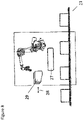
- the modular construction according to the invention is in 1 shown schematically and divides a device for the automated removal of workpieces arranged in a container into a central handling module 1, on which the gripper kinematics are arranged, which are in particular a robot or a surface portal for moving the gripper.
- the handling module 1 is combined with a feed module 2, which has an arrangement for providing the containers with the workpieces.
- the arrangement of handling module 1 and feed module 2 is usually combined with an output module 3, on which the gripper of the handling module 1 deposits the individual workpieces.
- the output module 3 usually has a transport section for transporting away the workpieces.
- Interfaces 4 and 5 are provided between the handling module 1, the feed module 2 and the output module 3, via which the individual modules are connected to one another.
- This can be a mechanical interface.
- an electrical, pneumatic and/or hydraulic interface can also be provided.
- the interface can coordinate of operation between the individual modules.
- an interface to a manufacturing system can be provided.
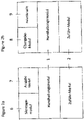
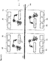
- FIGs 2a and 2b are two variants of the in 1 shown basic module structure.
- an assembly module 6 is provided in addition to the handling module 1, the feed module 2 and the output module 7.
- Workpieces can be processed on this, for example, and/or assembly steps can be carried out on the workpieces.
- the workpieces can first be given from the handling module to the assembly module and then given back to the output module 7 via the handling module.
- FIG 2b a variant is shown in which the handling module 1 is connected to a palletizing cell 9 via a transfer module 8 .
- the transfer module can be a conveyor belt, for example, on which palletizing baskets can be transported to the palletizing cell.
- the workpieces can then first be placed in the palletizing baskets in the area of the transfer module 8 .
- the palletizing baskets are then transported into the palletizing cell 9, for which purpose a corresponding transport device is preferably provided.
- the transfer module can either be attached to a palletizing cell or it can be integrated as a transfer module in a palletizing cell, thus enabling direct input into the palletizing cell.
- the handling module which can be combined with different feed modules, serves as the basic unit for all variants of the device according to the invention.
- the unit made up of handling module and feed module can then be expanded with different types of outfeed module, or attached to existing transport, processing and/or assembly units.
- the modular structure makes it possible to serve the diverse and varied requirements of customers with regard to production, processing and assembly lines without a completely new design in each case. Furthermore, the interfaces allow quick and easy installation on site, since the individual modules are delivered pre-assembled and only have to be connected to one another at the installation site.
- the handling module 1 and the feed module 2 in particular each have a cell frame.
- This usually includes a base plate and one or more cell walls, which prevent unauthorized access to the working area of the handling device when the device is set up.
- the cell frames of the individual modules are connected to one another via mechanical connection points. Furthermore, electrical, pneumatic and/or hydraulic interfaces can be provided for connecting the modules.
- the individual modules can be delivered fully assembled and then connected to one another in just a few simple steps.
- the handling module 1 has the gripper kinematics, ie an arrangement via which the gripper can be moved to remove the workpieces from the container and to place them on an intermediate or final depository.
- a robot is used for this, in particular a six-axis robot.
- a surface portal can also be used.
- the handling module has a corresponding control for the gripper kinematics and the gripper.
- the handling module also has an operating module with a user interface, via which the controller can be accessed.
- an electrical, pneumatic and/or hydraulic supply can be provided, in particular in a switch cabinet.
- the user interface and the control cabinet are preferably accessible from the outside of the cell walls.
- the device according to the invention for removing workpieces from the containers has an object detection device with a sensor.
- a sensor This is arranged in the area of the feed module and can be arranged above a container to be emptied in order to grasp the workpieces in the container.
- it is a 3D laser scanner.
- the data from the sensor is evaluated in order to identify the individual workpieces and their positions and to determine a workpiece that is suitable for gripping.
- a path is then planned for the gripper or for its gripper kinematics, in particular for the robot 10.
- the sensor is connected to the control of the handling module via an interface.
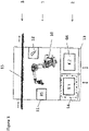
- the handling module 1 which has a robot 10 , the user interface 11 and the power supply 12 .
- the handling module 1 has two open sides, via which it is connected to a feed module 2 and an output module 3 .
- the exemplary embodiment shown has the feed module 2 on two feed areas for containers arranged next to one another, which are each accessible from the outside via a door 13 .
- the containers 66 can be pushed into or removed from the respective feed area, for example, using a forklift.
- a hood 14 is provided, which can be optionally pushed over the feed area for one or the other container. If one of the two containers is completely empty, the hood moves over it and releases the other container for the gripper. The grapple can then continue with the emptying seamlessly. Through the hood 14, which the Covering the feed area for the now emptied container, it can now be safely removed and replaced with a full container.
- the output module is in 3 a transport path 15, on which the workpieces removed from the containers are deposited individually. If necessary, the transport route can have corresponding receptacles for this. In the embodiment, it is a conveyor belt.
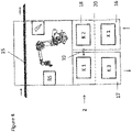
- This in 4 illustrated embodiment differs from that in 3 illustrated embodiment by a differently designed feed module 2.
- the feed module is connected to an automated container feed section 16 and an automated container discharge section 17, via which full containers are supplied and empty containers are removed.
- the feed direction of the feed path 16 is opposite to the discharge direction of the discharge path 17.
- a transverse shuttle 18 is therefore provided in the feed module 2, via which containers can be moved in the direction of movement 19 transversely to the feed or discharge direction. Containers are thus transported from the feed line 16 into the feed area of the feed module. There the containers can be emptied by the handling module. An emptied container is then moved via the cross shuttle 18 to a transfer area for transfer to the discharge section 17, from where the emptied containers are removed. Alternatively, a filled container can also first be transported via the transverse shuttle within the feed arrangement, and only then can workpieces be removed from the container.
- a light barrier 20 is also provided, which is arranged between the feed module and the feed path 16 and/or discharge path 17 . The light barrier prevents people from accessing the area of the feed module.
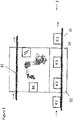
- a transport path 21 for the container in particular a conveyor belt, over which takes place both the supply of full containers and the discharge of emptied containers.
- the supply and removal takes place without a change of direction simply by further transport on the transport route.
- the feed module 2 preferably has openings on its narrow sides 22 and 23 through which the transport path with the containers passes.
- the feed arrangement on a turntable 24, on which several containers can be arranged can be arranged.
- the turntable 24 can be rotated about a vertical axis of rotation 26 in order to bring the containers from a feed area for the containers into the working area of the handling module.
- the turntable 24 preferably has a partition 25 which separates the working area of the gripper from the feed area for the containers.
- the supply and removal of the containers to and from the turntable can again be carried out using a transport vehicle, for example a forklift.
- a transport vehicle for example a forklift.
- such a turntable can also be combined with an automated infeed and/or outfeed section for the containers.
- an intermediate station 27 is also provided in the area of the handling module 1, on which the gripper of the handling module can deposit workpieces that are removed from the containers in the area of the feed module and, if necessary, can pick them up again.
- the intermediate station enables a more precise grip and thus a more precise placement in the area of the output module.
- Any feed module can be used as the feed module 2, which Figures 7a and 7b is shown only schematically. Any output module can also be used.
- a transport section 15 is again used as the output module.
- a palletizing cell 28 is provided as the output module 3, in which the workpieces are deposited.
- a further exemplary embodiment is shown, in which the supply and removal of the containers takes place via a conveyor belt 21 . Furthermore, a clipboard 27 is provided here in the area of the handling module. The storage takes place in palletizing baskets 29, which are moved via a transport path 28 to a palletizing cell.
- handling modules 1 are combined with a single output module 34, again a conveyor belt in the exemplary embodiment.
- the handling modules work in parallel and each place individual workpieces on the output module 34 .
- the individual handling modules 1 are each combined with separate feed modules 35 and thus form removal units 30 to 33.
- two removal units 30 and 32 are provided on opposite sides of the conveyor belt 34, so that loading takes place from opposite sides. Furthermore, in each case two removal units are arranged one behind the other along the conveyor belt 34 .
- the handling modules 36 and 37 are provided, which are combined with an intermediate station via an intermediate module 38 .
- the individual modules can be used as in 10 shown schematically offset combined with each other, but preferably aligned.
- the arrangement of the two handling modules 36 and 37 and the intermediate module 38 is then combined with a feed module 39 and an output module 40 .
- the first handling module 37 removes workpieces from the containers in the area of the feed module 39 and places them on the intermediate station of the intermediate module 38. from where they are picked up again via the second handling module 36 and deposited in the area of the output module 40 .
- the feed module can interact with a driverless transport system.
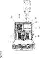
- a robot module according to the present invention is shown, which can be used, for example, as a handling module in a device according to the invention for removing workpieces from a container, as was presented above.
- the robot module can also be used independently of this application in a wide range of tasks.
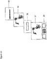
- the robot module 1 includes a cell frame which consists of a base plate 41 and the cell walls 42 and 43 .
- the robot 10 is mounted on the base plate.
- the robot 10 is a six-axis industrial robot.
- the base plate 41 is rectangular, with the two cell walls 42 and 43 being arranged on opposite narrow sides of the base plate 41 .
- the two long sides of the robot module are open.
- the working area of the robot 10 extends beyond the area of the robot module through the open sides into the adjacent area.
- the robot module 1 can be combined with other modules which, for example, provide or receive workpieces that are processed and/or handled by the robot.
- the cell walls are constructed from corner struts 46 which are connected to one another via cross struts 47 . Furthermore, the cell walls have a lining. The cell walls prevent access to the work area of the robot 10.
- a control module for the robot is integrated into the robot module. Furthermore, the robot module has a user interface, which is arranged on an outer wall of the cell wall 42 in the exemplary embodiment.
- the interface has a display 44 and input elements. Furthermore, a touch screen 45 is provided as an input/output element.
- the control module can be accessed via the user interface and, in particular, the movement of the robot can be controlled.
- the robot module has an electrical, pneumatic and/or hydraulic supply 12 which is accessible from the outside via a switch cabinet arranged in the area of the other cell wall 43 .
- This is a power supply not only for the robot or the robot module itself, but also for other modules, which can be connected via appropriate interfaces.
- the robot module according to the invention can be connected to other modules in order to form a processing, assembly and/or handling unit.
- the further modules preferably also have a cell frame which can be mechanically connected to the cell frame of the robot module.
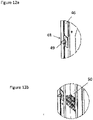
- the cell frame of the robot module shown in the exemplary embodiment has mechanical connection points 48 for connection to other modules. These are provided on the corner braces 46 . In the exemplary embodiment, these are screw bosses 49, which can be pushed through corresponding openings in the cell frame of another module and screwed to it.
- a pneumatic and/or hydraulic interface 50 is provided for this purpose, via which a further module can be connected to the hydraulic and/or pneumatic supply of the robot module.
- the robot module has a hydraulic supply, this preferably includes a pump that provides high-pressure hydraulic fluid. If a pneumatic supply is provided, this preferably includes a compressor which makes compressed air available.
- the electrical connection of a further module can also take place via the electrical supply of the robot module.
- An electrical interface is preferably also provided for this purpose.
- an interface to the control module of the robot can be provided, via which the operation of the robot module can be coordinated with the operation of other modules.
- the further module can itself have a controller which communicates with the control module of the robot module 1 via the interface, preferably communicates bidirectionally.
- actuators of a further module can also be controlled via the control module of the robot module.
- sensor data from sensors which are arranged in a further module can be evaluated via the control module of the robot module.
- the robot module is constructed in such a way that it can be delivered to the installation site as a completely pre-assembled unit.
- the cell frame can optionally be reinforced for transport via a longitudinal strut, which connects the cell walls to one another in their upper region.
- the robot module can be transported either hanging, for example by connecting hooks to the longitudinal strut or the cell walls, or by transporting the robot module hanging on the robot.
- the robot module for example be transported by a forklift, which grips under the base plate.
- the robot module already has a complete wiring of the robot with the control module, the power supply and the user interface. As a result, only a few assembly steps have to be carried out at the installation site.
- the other modules are preferably also preassembled accordingly and only have to be mechanically connected to the robot module and connected to the power supply and/or the control module of the robot module via the appropriate interfaces.
- Feeding module 2 and robot module or handling module 1 preferably form a device for removing workpieces arranged in a container, in particular for removing workpieces arranged in a container in a disordered manner.
- the feed module 2 also has a cell frame which can be connected to the cell frame of the handling module 1 .
- the cell frame has a base plate 51 and cell walls 52, 53 and 54.
- one side of the feed module is open and is connected to an open side of the handling module, so that the robot 10 can work in the area of the feed module.
- the cell frame of the feed module in turn has corner struts 56 which are connected to one another via transverse struts 47 and longitudinal struts. Furthermore, covers or windows are also provided here, which protect the area of the feed module from unauthorized access.
- the corner struts 46 arranged on the open side of the cell frame can be mechanically connected to the corner struts 46 of the cell frame of the robot module, in particular via the in 12a mounting points shown.
- connection to the power supply of the robot module is made via the in Figure 12b shown interface 50, which is connected to a corresponding interface 70 of the feed module.
- the interface 70 of the feeder module is arranged inside the feeder module and is accessible via a door in an outer wall. Furthermore, sensors and/or actuators of the feed module can be connected to the control module of the robot module via an electronic interface that is not shown.
- the feed module 2 is also completely preassembled and has all the wiring, which only requires a connection to the interfaces of the robot module.
- the feed module can, for example, be hung on a hook via the bores 48 and transported hanging. Alternatively, transport using a forklift is also conceivable here.
- the combination of the handling module 1 and the feed module 2 is now shown, which together form a device for removing workpieces from containers 66 .
- the handling module 1 is also connected to an output module 3 on its free side opposite the feed module, which will be discussed in more detail later.
- the feed module forms a feed arrangement for providing containers from which the robot can remove workpieces, which can also be used independently of the modular structure according to the invention.
- the modular design described above is particularly preferred here.
- the feed arrangement formed by the feed module is accessible on one side for the provision and removal of containers.
- sliding doors 55 are provided for this purpose, which are let into the cell wall 54 .
- two feed areas provided next to one another in the feed arrangement are accessible for one container each.
- the containers can be placed in the feed arrangement using a forklift truck 65, for example, or can be removed from the latter after they have been emptied.
- the provision of two containers has the advantage that after a first container has been emptied, the device can immediately continue with the emptying of the second container without the removal operation having to be interrupted in order to replace the container. Rather, the empty container can be removed and replaced with a full container while the other container is being emptied.
- a displaceable hood 57 is provided for this purpose, which can be pushed either over the feed area for the first container or over the feed area for the second container, thus separating it from the working area of the gripper.
- the doors 55 are preferably designed in such a way that they can only be opened when the feed area assigned to the respective door is separated from the working area of the gripper by the displaceable hood 47 . This ensures that there is no risk of injury when removing and placing a container in the feed arrangement.
- the device according to the invention for removing workpieces from the containers has an object detection device with a sensor 63 which can be arranged above the respective container and detects the workpieces in the container.
- a sensor 63 which can be arranged above the respective container and detects the workpieces in the container.
- it is a 3D laser scanner.
- the data from the sensor arrangement are evaluated in order to identify the individual workpieces and their positions and to determine a workpiece that is suitable for gripping. Using the position data of this workpiece, a path is then planned for the gripper or for its gripper kinematics, in particular for the robot 10.
- the sensor arrangement 63 is arranged to be movable in the feed arrangement.
- a displacement arrangement 64 is provided, along which the sensor 63 can be arranged selectively above the first and the second container.
- this has the advantage that only one sensor arrangement has to be used to detect the workpieces, since this can be moved over the respective container, depending on the container that is to be emptied.
- the sensor arrangement can be moved away from an area above the container, so that the working area of the gripper is not restricted by the sensor arrangement. After a workpiece has been removed, the sensor assembly is then moved back over the container to detect the remaining workpieces.
- the sensor arrangement 63 is connected to the control module of the robot module, with the data from the sensor module being evaluated via the control module.
- the handling module is, as in 15 and 16 shown connected to an output module on the open side opposite the feed module.
- this also has a cell frame which is connected to the cell frame of the handling module 1 .
- the output unit has a transport path on which the gripper of the handling unit deposits the workpieces removed from the container.
- the transport section is a roller conveyor. If necessary, nests can be transported on this, in which the workpieces are placed.
- the cell frame of the output module protects against unauthorized access to the working area of the robot 10. Doors 71 are provided for maintenance work, via which the interior of the cell formed by the feed module, handling module and output module can be entered.
- the device according to the invention for removing workpieces from a container can be used in a large number of different areas with only little construction and assembly effort.
- the handling module according to the invention can be combined with output units already provided by the customer, so that only a corresponding connection of the handling module has to be redesigned, in particular by constructing a cell frame for the output module.
- the handling module can also be combined with feed modules that the customer may already have.
- the robot module according to the invention can also be used in other applications for the simple and cost-effective construction of a robot cell.
- it can be combined with processing and/or assembly modules.
Landscapes
- Engineering & Computer Science (AREA)
- Robotics (AREA)
- Mechanical Engineering (AREA)
- Manipulator (AREA)
- Toys (AREA)
Claims (13)
- Module de robot (1) comprenant un cadre de cellule et un robot (10), le cadre de cellule comportant une plaque de base (41), sur laquelle est monté le robot, et au moins une paroi de cellule (42, 43) reliée à la plaque de base, et le module de robot étant équipé d'un module de contrôle pour le robot, le cadre de cellule comportant des montants d'angle (46) s'étendant verticalement, les montants d'angle étant reliés par des entretoises (47) s'étendant horizontalement,
caractérisé en ce que
sur les montants d'angle, des points de liaison mécaniques (48) sont prévus pour la liaison avec au moins un autre module, et le robot comportant une zone de travail qui est plus grande que la surface de base de la plaque de base, la zone de travail du robot étant d'une grandeur telle qu'elle s'étend sur deux côtés du cadre de cellule au-delà de sa surface de base et un préhenseur du module de robot peut prélever des pièces dans une zone, qui est disposée en dehors d'un premier côté ouvert du cadre de cellule et les déposer dans une seconde zone qui est disposée en dehors d'un second côté ouvert du cadre de cellule. - Module de robot selon la revendication 1, comprenant une alimentation électrique, pneumatique et/ou hydraulique, au moins une interface électrique, pneumatique et/ou hydraulique (50) étant de préférence prévue pour la liaison avec d'autres modules, et/ou le module de robot comportant une interface, qui permet une coordination du fonctionnement du module de robot avec d'autres modules et ou le module de robot comportant une interface pour un système de contrôle de production, qui permet une coordination du fonctionnement avec un autre système de production.
- Module de robot selon l'une des revendications précédentes, dans lequel la plaque de base du cadre de cellule présente une forme rectangulaire et présente de préférence un côté plus long et un côté plus court et/ou dans lequel le cadre de cellule comporte au moins deux parois de cellule, le cadre de cellule comportant de préférence des parois de cellule sur deux côtés et étant ouvert sur deux côtés et/ou dans lequel les deux parois de cellule sont disposées de préférence sur des côtés opposés de la plaque de base, en particulier sur des côtés étroits opposés, ou dans lequel les deux parois de cellule sont disposées sur des côtés adjacents de la plaque de base.
- Module de robot selon l'une des revendications précédentes, dans lequel au moins deux des parois latérales du cadre de cellule sont reliées dans une zone supérieure par une traverse de transport.
- Module de robot selon l'une des revendications précédentes, comprenant un module de commande, qui est disposé de préférence sur un côté extérieur d'une paroi de cellule, et/ou comprenant une armoire électrique, qui est de préférence accessible depuis un côté extérieur d'une paroi de cellule, et/ou étant équipé d'un appareil de commande portatif.
- Module de robot selon l'une des revendications précédentes, dans lequel il s'agit d'un module de manipulation, le module de contrôle présentant une routine de contrôle pour la préhension et/ou le dépôt de pièces au moyen du robot, le module de robot permettant de manière particulièrement préférée une préhension de pièces disposées de manière non ordonnée dans un contenant, le module de contrôle comportant de préférence une interface avec un dispositif de reconnaissance d'objet pour détecter les pièces dans le contenant.
- Installation de manipulation pour pièces comprenant un module de robot selon l'une des revendications précédentes et un module intermédiaire (38) doté d'un cadre de cellule et d'un poste intermédiaire, le cadre de cellule du module intermédiaire comportant des points de liaison mécaniques et de préférence une interface électrique, pneumatique et/ou hydraulique pour la liaison avec au moins un autre module et de préférence avec deux modules, et/ou le module intermédiaire comportant une interface, qui permet une coordination du fonctionnement du module intermédiaire avec d'autres modules, et/ou le module intermédiaire comportant une interface pour un système de contrôle de production, qui permet une coordination du fonctionnement avec un autre système de production.
- Installation de manipulation pour pièces comprenant un module de robot selon l'une des revendications précédentes et un module d'alimentation (39) doté d'un cadre de cellule et d'un agencement pour mettre à disposition un contenant avec des pièces, le cadre de cellule du module d'alimentation comportant des points de liaison mécaniques et de préférence une interface électrique, pneumatique et/ou hydraulique pour la liaison avec le module de robot, et/ou le module d'alimentation comportant une interface, qui permet une coordination du fonctionnement du module d'alimentation avec d'autres modules, et/ou le module d'alimentation comportant une interface pour un système de contrôle de production, qui permet une coordination du fonctionnement avec un autre système de production.
- Installation de manipulation selon la revendication 8, dans laquelle le cadre de cellule comporte une plaque de base, sur laquelle est disposé l'agencement pour mettre à disposition au moins un contenant avec des pièces, et/ou dans laquelle le cadre de cellule comporte au moins deux parois de cellule et est ouvert sur au moins un côté, l'agencement pour mettre à disposition un contenant avec des pièces étant de préférence accessible de l'extérieur sur au moins un côté, en particulier par une porte ou barrière photoélectrique disposée sur au moins un côté et/ou une voie d'alimentation et/ou de sortie de contenants automatique disposée sur au moins un côté, ce côté étant de préférence opposé au côté ouvert, et/ou dans laquelle le côté ouvert est de préférence le côté large du module d'alimentation.
- Installation de manipulation selon la revendication 8 ou 9, dans laquelle l'agencement pour mettre à disposition un contenant avec des pièces peut recevoir au moins deux contenants.
- Installation de manipulation selon la revendication 10, dans lequel le module d'alimentation comporte un dispositif de séparation, par le biais duquel une zone d'alimentation pour un contenant peut être séparée d'une zone de travail, un capot étant en particulier prévu, qui est disposé dans le module d'alimentation de manière à recouvrir la zone d'alimentation de manière sélective pour l'un ou l'autre contenant.
- Installation de manipulation selon la revendication 10, dans laquelle le module d'alimentation comporte un agencement de transport pour le transport des contenants à l'intérieur du module d'alimentation, l'agencement de transport pouvant de préférence coopérer avec une voie d'alimentation et/ou de sortie de contenants automatique, et/ou dans laquelle une barrière photoélectrique est prévue, qui sécurise la zone d'alimentation.
- Installation de manipulation comprenant un module de robot selon l'une des revendications 1 à 6 et un module de distribution, d'usinage et/ou d'assemblage pour la liaison avec le module de robot, comprenant un emplacement de dépôt de pièces sur lequel les pièces sont déposées séparément et/ou dans une position définie et des points de liaison mécaniques pour la liaison avec un module de robot selon l'une des revendications précédentes, le module de distribution comportant de préférence une voie de transport pour les pièces et le module d'usinage et/ou d'assemblage comportant de préférence une unité d'usinage et/ou d'assemblage, qui usine et/ou assemble les pièces.
Applications Claiming Priority (1)
| Application Number | Priority Date | Filing Date | Title |
|---|---|---|---|
| DE102014008107.9A DE102014008107A1 (de) | 2014-06-02 | 2014-06-02 | Robotermodul |
Publications (3)
| Publication Number | Publication Date |
|---|---|
| EP2952298A2 EP2952298A2 (fr) | 2015-12-09 |
| EP2952298A3 EP2952298A3 (fr) | 2016-12-21 |
| EP2952298B1 true EP2952298B1 (fr) | 2022-07-13 |
Family
ID=52813898
Family Applications (1)
| Application Number | Title | Priority Date | Filing Date |
|---|---|---|---|
| EP15159031.2A Active EP2952298B1 (fr) | 2014-06-02 | 2015-03-13 | Module de robot |
Country Status (3)
| Country | Link |
|---|---|
| US (1) | US9827676B2 (fr) |
| EP (1) | EP2952298B1 (fr) |
| DE (1) | DE102014008107A1 (fr) |
Families Citing this family (18)
| Publication number | Priority date | Publication date | Assignee | Title |
|---|---|---|---|---|
| DE102014008108A1 (de) | 2014-06-02 | 2015-12-03 | Liebherr-Verzahntechnik Gmbh | Vorrichtung zum automatisierten Entnehmen von in einem Behälter angeordneten Werkstücken |
| US10857674B2 (en) | 2015-04-28 | 2020-12-08 | Seiko Epson Corporation | Robot system and robot |
| DE202015106871U1 (de) * | 2015-12-16 | 2017-03-17 | Kuka Industries Gmbh | Bearbeitungseinrichtung |
| DE102016015122A1 (de) | 2016-12-20 | 2018-06-21 | Drägerwerk AG & Co. KGaA | Verfahren zur Steuerung einer Vorrichtung zum extrakorporalen Blutgasaustausch, Vorrichtung zum extrakorporalen Blutgasautausch sowie Steuervorrichtung zum Steuern einer Vorrichtung zum extrakorporalen Blutgasaustausch |
| DE102017000524A1 (de) | 2017-01-20 | 2018-07-26 | Liebherr-Verzahntechnik Gmbh | Vorrichtung zum automatisierten Entnehmen von in einem Behälter angeordneten Werkstücken |
| DE102017000527A1 (de) | 2017-01-20 | 2018-07-26 | Liebherr-Verzahntechnik Gmbh | Vorrichtung zum automatisierten Entnehmen von in einem Behälter angeordneten Werkstücken |
| JP2018126795A (ja) * | 2017-02-06 | 2018-08-16 | セイコーエプソン株式会社 | ロボットシステム |
| WO2018191818A1 (fr) | 2017-04-18 | 2018-10-25 | Clearpath Robotics Inc. | Véhicule de transport de matériau autonome sans conducteur |
| WO2018213931A1 (fr) * | 2017-05-25 | 2018-11-29 | Clearpath Robotics Inc. | Systèmes et procédés d'orientation de processus au moyen d'un bras robotisé |
| CN108381509B (zh) * | 2018-03-19 | 2021-03-02 | 京东方科技集团股份有限公司 | 智能抓取装置及其控制方法、智能抓取控制系统 |
| DE102018209174A1 (de) * | 2018-06-08 | 2019-12-12 | Kuka Deutschland Gmbh | Fahrgeschäft |
| DE102019114439B4 (de) * | 2019-05-29 | 2021-03-25 | TGA Technische Gebäudeausrüstung Meiningen GmbH | Modulares Automatisierungssystem und Verfahren zu dessen Betreiben |
| RU201065U1 (ru) * | 2020-06-15 | 2020-11-25 | Федеральное государственное бюджетное образовательное учреждение высшего образования "МИРЭА - Российский технологический университет" | Модульная производственная ячейка на основе малогабаритного робота |
| US12122367B2 (en) | 2020-09-10 | 2024-10-22 | Rockwell Automation Technologies, Inc. | Systems and methods for operating one or more self-driving vehicles |
| TWI780772B (zh) * | 2021-06-16 | 2022-10-11 | 中傳科技股份有限公司 | 刀具與刀把的配對系統與配對方法 |
| WO2023041184A1 (fr) * | 2021-09-20 | 2023-03-23 | Abb Schweiz Ag | Unité de base pour système d'alimentation, système d'alimentation, système industriel, et procédé de manipulation d'un système d'alimentation |
| US11932501B2 (en) * | 2022-04-14 | 2024-03-19 | Dexterity, Inc. | Containerized robotic system |
| JP7492694B1 (ja) | 2022-11-16 | 2024-05-30 | 株式会社Mujin | ロボットシステム搬送ユニットセル及びその動作方法 |
Family Cites Families (13)
| Publication number | Priority date | Publication date | Assignee | Title |
|---|---|---|---|---|
| DE3413255A1 (de) * | 1984-04-07 | 1985-10-17 | Krone Gmbh, 1000 Berlin | Verfahren und vorrichtung fuer ein modulares, flexibles montagesystem |
| DE3532305A1 (de) * | 1985-09-11 | 1987-03-12 | Messer Griesheim Gmbh | Fertigungs- und/oder montagezelle fuer werkstuecke |
| DE4212178A1 (de) * | 1992-04-10 | 1993-10-14 | Klaus Dipl Ing Broetzmann | Automatisierte Montageeinrichtung |
| DE19519524C2 (de) * | 1995-05-27 | 2002-11-28 | Imt Robot Ag | Roboterzelle mit einem Roboter und einem Teilelager |
| NL1027332C2 (nl) * | 2004-10-25 | 2006-04-26 | Meerpaal B V De | Robotcel en werkwijze voor het opslaan van elementen in een robotcel. |
| US7238916B2 (en) * | 2004-11-19 | 2007-07-03 | Lincoln Global, Inc. | Robotic welding cell unit |
| WO2009039183A1 (fr) * | 2007-09-17 | 2009-03-26 | Maglev, Inc. | Unité de fabrication modulaire |
| DE102008019102A1 (de) | 2008-04-16 | 2009-10-29 | Siemens Aktiengesellschaft | Anordnung zum Transport von Substraten, Anordnung zum Handhaben von Substraten, Anordnung zum Herstellen elektronischer Baugruppen sowie Verfahren zum Handhaben von Substraten |
| DE102009040951B4 (de) * | 2009-09-11 | 2023-08-10 | Ralf Bär | Handhabungs-/Stapelvorrichtung für Paletten, Behälter oder dergleichen |
| JP2011224742A (ja) * | 2010-04-21 | 2011-11-10 | Canon Inc | ロボットセル |
| DE202010015780U1 (de) * | 2010-11-23 | 2011-03-03 | Goldfuss, Thomas | Flexible Roboterzelle |
| DE102012005735A1 (de) * | 2012-03-23 | 2013-09-26 | Aberle GmbH | Roboter-Zelle |
| DE102012013030A1 (de) | 2012-06-29 | 2014-04-24 | Liebherr-Verzahntechnik Gmbh | Vorrichtung zum automatischen Entnehmen von in einem Behälter angeordneten Werkstücken |
-
2014
- 2014-06-02 DE DE102014008107.9A patent/DE102014008107A1/de not_active Ceased
-
2015
- 2015-03-13 EP EP15159031.2A patent/EP2952298B1/fr active Active
- 2015-06-02 US US14/728,526 patent/US9827676B2/en active Active
Also Published As
| Publication number | Publication date |
|---|---|
| US9827676B2 (en) | 2017-11-28 |
| EP2952298A3 (fr) | 2016-12-21 |
| DE102014008107A1 (de) | 2015-12-03 |
| US20150343638A1 (en) | 2015-12-03 |
| EP2952298A2 (fr) | 2015-12-09 |
Similar Documents
| Publication | Publication Date | Title |
|---|---|---|
| EP2952298B1 (fr) | Module de robot | |
| EP2952297B1 (fr) | Module d'apport et dispositif avec un tel module pour le prélèvement automatisé de pièces agencées dans un récipient | |
| EP3114017B1 (fr) | Poste de production, usine de production et procédé | |
| EP2952296B1 (fr) | Dispositif de prélèvement automatisé de pièces agencées dans un récipient | |
| EP3494073A1 (fr) | Système de préparation de commandes | |
| EP3351351B1 (fr) | Dispositif de prélèvement automatisée de pièces à usiner agencées dans un récipient | |
| DE102009052547A1 (de) | Robotersystem und Arbeitsverfahren eines Robotersystems | |
| EP1926572A1 (fr) | Installation d'usinage | |
| EP3620422B1 (fr) | Transporteur sans conducteur | |
| DE102018213680A1 (de) | Vorrichtung zum Sortieren von Waren | |
| WO2017202961A1 (fr) | Station de fabrication et procédé de fabrication | |
| DE102014102990B4 (de) | Fertigungsstation | |
| AT520959A2 (de) | Kommissionierstation und Verfahren zum automatischen Kommissionieren von Waren | |
| EP2607271B1 (fr) | Procédé de préparation de commandes d'articles et dispositif de préparation de commandes conçu à cet effet | |
| DE102007017365A1 (de) | Verfahren zur Lagerung von Lagergut in einem Lagerregal mit mehreren Regaleinheiten und einem Transportschacht sowie ein solches Lagerregal | |
| EP1980490A2 (fr) | Installation de chargement de bagages dans un conteneur | |
| WO1996015963A1 (fr) | Dispositif de desserte de casiers | |
| EP3509973B1 (fr) | Dispositif de transport robotique pour transporter des petites pièces et procédé pouvant être mis en oeuvre avec ledit dispositif robotique | |
| WO2017198280A1 (fr) | Système de préparation de commandes | |
| EP2036664B1 (fr) | Installation de traitement pour pièces à usiner | |
| DE102018213677A1 (de) | Vorrichtung zum Sortieren von Waren | |
| EP3459879A1 (fr) | Système de stockage robotisé | |
| EP4444637B1 (fr) | Navette de prélèvement et procédé de prélèvement à l'intérieur d'une allée de rayonnages pour navettes | |
| DE202023106747U1 (de) | System für den Materialtransport | |
| DE102018213678B4 (de) | Vorrichtung zum Sortieren von Waren |
Legal Events
| Date | Code | Title | Description |
|---|---|---|---|
| PUAI | Public reference made under article 153(3) epc to a published international application that has entered the european phase |
Free format text: ORIGINAL CODE: 0009012 |
|
| AK | Designated contracting states |
Kind code of ref document: A2 Designated state(s): AL AT BE BG CH CY CZ DE DK EE ES FI FR GB GR HR HU IE IS IT LI LT LU LV MC MK MT NL NO PL PT RO RS SE SI SK SM TR |
|
| AX | Request for extension of the european patent |
Extension state: BA ME |
|
| PUAL | Search report despatched |
Free format text: ORIGINAL CODE: 0009013 |
|
| AK | Designated contracting states |
Kind code of ref document: A3 Designated state(s): AL AT BE BG CH CY CZ DE DK EE ES FI FR GB GR HR HU IE IS IT LI LT LU LV MC MK MT NL NO PL PT RO RS SE SI SK SM TR |
|
| AX | Request for extension of the european patent |
Extension state: BA ME |
|
| RIC1 | Information provided on ipc code assigned before grant |
Ipc: B25J 21/00 20060101ALI20161117BHEP Ipc: B65G 47/14 20060101ALI20161117BHEP Ipc: B25J 9/00 20060101AFI20161117BHEP Ipc: B25J 9/08 20060101ALI20161117BHEP |
|
| STAA | Information on the status of an ep patent application or granted ep patent |
Free format text: STATUS: REQUEST FOR EXAMINATION WAS MADE |
|
| 17P | Request for examination filed |
Effective date: 20170619 |
|
| STAA | Information on the status of an ep patent application or granted ep patent |
Free format text: STATUS: EXAMINATION IS IN PROGRESS |
|
| 17Q | First examination report despatched |
Effective date: 20201009 |
|
| GRAP | Despatch of communication of intention to grant a patent |
Free format text: ORIGINAL CODE: EPIDOSNIGR1 |
|
| STAA | Information on the status of an ep patent application or granted ep patent |
Free format text: STATUS: GRANT OF PATENT IS INTENDED |
|
| INTG | Intention to grant announced |
Effective date: 20220215 |
|
| GRAS | Grant fee paid |
Free format text: ORIGINAL CODE: EPIDOSNIGR3 |
|
| GRAA | (expected) grant |
Free format text: ORIGINAL CODE: 0009210 |
|
| STAA | Information on the status of an ep patent application or granted ep patent |
Free format text: STATUS: THE PATENT HAS BEEN GRANTED |
|
| AK | Designated contracting states |
Kind code of ref document: B1 Designated state(s): AL AT BE BG CH CY CZ DE DK EE ES FI FR GB GR HR HU IE IS IT LI LT LU LV MC MK MT NL NO PL PT RO RS SE SI SK SM TR |
|
| REG | Reference to a national code |
Ref country code: GB Ref legal event code: FG4D Free format text: NOT ENGLISH |
|
| REG | Reference to a national code |
Ref country code: CH Ref legal event code: EP |
|
| REG | Reference to a national code |
Ref country code: IE Ref legal event code: FG4D Free format text: LANGUAGE OF EP DOCUMENT: GERMAN |
|
| REG | Reference to a national code |
Ref country code: DE Ref legal event code: R096 Ref document number: 502015015950 Country of ref document: DE |
|
| REG | Reference to a national code |
Ref country code: AT Ref legal event code: REF Ref document number: 1504027 Country of ref document: AT Kind code of ref document: T Effective date: 20220815 |
|
| REG | Reference to a national code |
Ref country code: LT Ref legal event code: MG9D |
|
| REG | Reference to a national code |
Ref country code: NL Ref legal event code: MP Effective date: 20220713 |
|
| PG25 | Lapsed in a contracting state [announced via postgrant information from national office to epo] |
Ref country code: SE Free format text: LAPSE BECAUSE OF FAILURE TO SUBMIT A TRANSLATION OF THE DESCRIPTION OR TO PAY THE FEE WITHIN THE PRESCRIBED TIME-LIMIT Effective date: 20220713 Ref country code: RS Free format text: LAPSE BECAUSE OF FAILURE TO SUBMIT A TRANSLATION OF THE DESCRIPTION OR TO PAY THE FEE WITHIN THE PRESCRIBED TIME-LIMIT Effective date: 20220713 Ref country code: PT Free format text: LAPSE BECAUSE OF FAILURE TO SUBMIT A TRANSLATION OF THE DESCRIPTION OR TO PAY THE FEE WITHIN THE PRESCRIBED TIME-LIMIT Effective date: 20221114 Ref country code: NO Free format text: LAPSE BECAUSE OF FAILURE TO SUBMIT A TRANSLATION OF THE DESCRIPTION OR TO PAY THE FEE WITHIN THE PRESCRIBED TIME-LIMIT Effective date: 20221013 Ref country code: NL Free format text: LAPSE BECAUSE OF FAILURE TO SUBMIT A TRANSLATION OF THE DESCRIPTION OR TO PAY THE FEE WITHIN THE PRESCRIBED TIME-LIMIT Effective date: 20220713 Ref country code: LV Free format text: LAPSE BECAUSE OF FAILURE TO SUBMIT A TRANSLATION OF THE DESCRIPTION OR TO PAY THE FEE WITHIN THE PRESCRIBED TIME-LIMIT Effective date: 20220713 Ref country code: LT Free format text: LAPSE BECAUSE OF FAILURE TO SUBMIT A TRANSLATION OF THE DESCRIPTION OR TO PAY THE FEE WITHIN THE PRESCRIBED TIME-LIMIT Effective date: 20220713 Ref country code: FI Free format text: LAPSE BECAUSE OF FAILURE TO SUBMIT A TRANSLATION OF THE DESCRIPTION OR TO PAY THE FEE WITHIN THE PRESCRIBED TIME-LIMIT Effective date: 20220713 Ref country code: ES Free format text: LAPSE BECAUSE OF FAILURE TO SUBMIT A TRANSLATION OF THE DESCRIPTION OR TO PAY THE FEE WITHIN THE PRESCRIBED TIME-LIMIT Effective date: 20220713 |
|
| PG25 | Lapsed in a contracting state [announced via postgrant information from national office to epo] |
Ref country code: PL Free format text: LAPSE BECAUSE OF FAILURE TO SUBMIT A TRANSLATION OF THE DESCRIPTION OR TO PAY THE FEE WITHIN THE PRESCRIBED TIME-LIMIT Effective date: 20220713 Ref country code: IS Free format text: LAPSE BECAUSE OF FAILURE TO SUBMIT A TRANSLATION OF THE DESCRIPTION OR TO PAY THE FEE WITHIN THE PRESCRIBED TIME-LIMIT Effective date: 20221113 Ref country code: HR Free format text: LAPSE BECAUSE OF FAILURE TO SUBMIT A TRANSLATION OF THE DESCRIPTION OR TO PAY THE FEE WITHIN THE PRESCRIBED TIME-LIMIT Effective date: 20220713 Ref country code: GR Free format text: LAPSE BECAUSE OF FAILURE TO SUBMIT A TRANSLATION OF THE DESCRIPTION OR TO PAY THE FEE WITHIN THE PRESCRIBED TIME-LIMIT Effective date: 20221014 |
|
| REG | Reference to a national code |
Ref country code: DE Ref legal event code: R097 Ref document number: 502015015950 Country of ref document: DE |
|
| PG25 | Lapsed in a contracting state [announced via postgrant information from national office to epo] |
Ref country code: SM Free format text: LAPSE BECAUSE OF FAILURE TO SUBMIT A TRANSLATION OF THE DESCRIPTION OR TO PAY THE FEE WITHIN THE PRESCRIBED TIME-LIMIT Effective date: 20220713 Ref country code: RO Free format text: LAPSE BECAUSE OF FAILURE TO SUBMIT A TRANSLATION OF THE DESCRIPTION OR TO PAY THE FEE WITHIN THE PRESCRIBED TIME-LIMIT Effective date: 20220713 Ref country code: DK Free format text: LAPSE BECAUSE OF FAILURE TO SUBMIT A TRANSLATION OF THE DESCRIPTION OR TO PAY THE FEE WITHIN THE PRESCRIBED TIME-LIMIT Effective date: 20220713 Ref country code: CZ Free format text: LAPSE BECAUSE OF FAILURE TO SUBMIT A TRANSLATION OF THE DESCRIPTION OR TO PAY THE FEE WITHIN THE PRESCRIBED TIME-LIMIT Effective date: 20220713 |
|
| PLBE | No opposition filed within time limit |
Free format text: ORIGINAL CODE: 0009261 |
|
| STAA | Information on the status of an ep patent application or granted ep patent |
Free format text: STATUS: NO OPPOSITION FILED WITHIN TIME LIMIT |
|
| PG25 | Lapsed in a contracting state [announced via postgrant information from national office to epo] |
Ref country code: SK Free format text: LAPSE BECAUSE OF FAILURE TO SUBMIT A TRANSLATION OF THE DESCRIPTION OR TO PAY THE FEE WITHIN THE PRESCRIBED TIME-LIMIT Effective date: 20220713 Ref country code: EE Free format text: LAPSE BECAUSE OF FAILURE TO SUBMIT A TRANSLATION OF THE DESCRIPTION OR TO PAY THE FEE WITHIN THE PRESCRIBED TIME-LIMIT Effective date: 20220713 |
|
| 26N | No opposition filed |
Effective date: 20230414 |
|
| PG25 | Lapsed in a contracting state [announced via postgrant information from national office to epo] |
Ref country code: AL Free format text: LAPSE BECAUSE OF FAILURE TO SUBMIT A TRANSLATION OF THE DESCRIPTION OR TO PAY THE FEE WITHIN THE PRESCRIBED TIME-LIMIT Effective date: 20220713 |
|
| PG25 | Lapsed in a contracting state [announced via postgrant information from national office to epo] |
Ref country code: SI Free format text: LAPSE BECAUSE OF FAILURE TO SUBMIT A TRANSLATION OF THE DESCRIPTION OR TO PAY THE FEE WITHIN THE PRESCRIBED TIME-LIMIT Effective date: 20220713 |
|
| PG25 | Lapsed in a contracting state [announced via postgrant information from national office to epo] |
Ref country code: MC Free format text: LAPSE BECAUSE OF FAILURE TO SUBMIT A TRANSLATION OF THE DESCRIPTION OR TO PAY THE FEE WITHIN THE PRESCRIBED TIME-LIMIT Effective date: 20220713 |
|
| REG | Reference to a national code |
Ref country code: CH Ref legal event code: PL |
|
| GBPC | Gb: european patent ceased through non-payment of renewal fee |
Effective date: 20230313 |
|
| REG | Reference to a national code |
Ref country code: BE Ref legal event code: MM Effective date: 20230331 |
|
| PG25 | Lapsed in a contracting state [announced via postgrant information from national office to epo] |
Ref country code: LU Free format text: LAPSE BECAUSE OF NON-PAYMENT OF DUE FEES Effective date: 20230313 |
|
| REG | Reference to a national code |
Ref country code: IE Ref legal event code: MM4A |
|
| PG25 | Lapsed in a contracting state [announced via postgrant information from national office to epo] |
Ref country code: GB Free format text: LAPSE BECAUSE OF NON-PAYMENT OF DUE FEES Effective date: 20230313 |
|
| PG25 | Lapsed in a contracting state [announced via postgrant information from national office to epo] |
Ref country code: LI Free format text: LAPSE BECAUSE OF NON-PAYMENT OF DUE FEES Effective date: 20230331 Ref country code: IT Free format text: LAPSE BECAUSE OF FAILURE TO SUBMIT A TRANSLATION OF THE DESCRIPTION OR TO PAY THE FEE WITHIN THE PRESCRIBED TIME-LIMIT Effective date: 20220713 Ref country code: IE Free format text: LAPSE BECAUSE OF NON-PAYMENT OF DUE FEES Effective date: 20230313 Ref country code: GB Free format text: LAPSE BECAUSE OF NON-PAYMENT OF DUE FEES Effective date: 20230313 Ref country code: FR Free format text: LAPSE BECAUSE OF NON-PAYMENT OF DUE FEES Effective date: 20230331 Ref country code: CH Free format text: LAPSE BECAUSE OF NON-PAYMENT OF DUE FEES Effective date: 20230331 |
|
| PG25 | Lapsed in a contracting state [announced via postgrant information from national office to epo] |
Ref country code: BE Free format text: LAPSE BECAUSE OF NON-PAYMENT OF DUE FEES Effective date: 20230331 |
|
| REG | Reference to a national code |
Ref country code: AT Ref legal event code: MM01 Ref document number: 1504027 Country of ref document: AT Kind code of ref document: T Effective date: 20230313 |
|
| PG25 | Lapsed in a contracting state [announced via postgrant information from national office to epo] |
Ref country code: AT Free format text: LAPSE BECAUSE OF NON-PAYMENT OF DUE FEES Effective date: 20230313 |
|
| PG25 | Lapsed in a contracting state [announced via postgrant information from national office to epo] |
Ref country code: AT Free format text: LAPSE BECAUSE OF NON-PAYMENT OF DUE FEES Effective date: 20230313 |
|
| PG25 | Lapsed in a contracting state [announced via postgrant information from national office to epo] |
Ref country code: BG Free format text: LAPSE BECAUSE OF FAILURE TO SUBMIT A TRANSLATION OF THE DESCRIPTION OR TO PAY THE FEE WITHIN THE PRESCRIBED TIME-LIMIT Effective date: 20220713 |
|
| PG25 | Lapsed in a contracting state [announced via postgrant information from national office to epo] |
Ref country code: BG Free format text: LAPSE BECAUSE OF FAILURE TO SUBMIT A TRANSLATION OF THE DESCRIPTION OR TO PAY THE FEE WITHIN THE PRESCRIBED TIME-LIMIT Effective date: 20220713 |
|
| PGFP | Annual fee paid to national office [announced via postgrant information from national office to epo] |
Ref country code: DE Payment date: 20250331 Year of fee payment: 11 |
|
| PG25 | Lapsed in a contracting state [announced via postgrant information from national office to epo] |
Ref country code: CY Free format text: LAPSE BECAUSE OF FAILURE TO SUBMIT A TRANSLATION OF THE DESCRIPTION OR TO PAY THE FEE WITHIN THE PRESCRIBED TIME-LIMIT; INVALID AB INITIO Effective date: 20150313 |
|
| PG25 | Lapsed in a contracting state [announced via postgrant information from national office to epo] |
Ref country code: HU Free format text: LAPSE BECAUSE OF FAILURE TO SUBMIT A TRANSLATION OF THE DESCRIPTION OR TO PAY THE FEE WITHIN THE PRESCRIBED TIME-LIMIT; INVALID AB INITIO Effective date: 20150313 |
|
| PG25 | Lapsed in a contracting state [announced via postgrant information from national office to epo] |
Ref country code: TR Free format text: LAPSE BECAUSE OF FAILURE TO SUBMIT A TRANSLATION OF THE DESCRIPTION OR TO PAY THE FEE WITHIN THE PRESCRIBED TIME-LIMIT Effective date: 20220713 |