EP2952377A1 - Module de condensateur pour machine de travail mobile - Google Patents
Module de condensateur pour machine de travail mobile Download PDFInfo
- Publication number
- EP2952377A1 EP2952377A1 EP14170948.5A EP14170948A EP2952377A1 EP 2952377 A1 EP2952377 A1 EP 2952377A1 EP 14170948 A EP14170948 A EP 14170948A EP 2952377 A1 EP2952377 A1 EP 2952377A1
- Authority
- EP
- European Patent Office
- Prior art keywords
- capacitor module
- casing
- electrode structure
- working machine
- cooling
- Prior art date
- Legal status (The legal status is an assumption and is not a legal conclusion. Google has not performed a legal analysis and makes no representation as to the accuracy of the status listed.)
- Granted
Links
Images
Classifications
-
- H—ELECTRICITY
- H01—ELECTRIC ELEMENTS
- H01G—CAPACITORS; CAPACITORS, RECTIFIERS, DETECTORS, SWITCHING DEVICES, LIGHT-SENSITIVE OR TEMPERATURE-SENSITIVE DEVICES OF THE ELECTROLYTIC TYPE
- H01G11/00—Hybrid capacitors, i.e. capacitors having different positive and negative electrodes; Electric double-layer [EDL] capacitors; Processes for the manufacture thereof or of parts thereof
- H01G11/14—Arrangements or processes for adjusting or protecting hybrid or EDL capacitors
- H01G11/18—Arrangements or processes for adjusting or protecting hybrid or EDL capacitors against thermal overloads, e.g. heating, cooling or ventilating
-
- H—ELECTRICITY
- H01—ELECTRIC ELEMENTS
- H01G—CAPACITORS; CAPACITORS, RECTIFIERS, DETECTORS, SWITCHING DEVICES, LIGHT-SENSITIVE OR TEMPERATURE-SENSITIVE DEVICES OF THE ELECTROLYTIC TYPE
- H01G11/00—Hybrid capacitors, i.e. capacitors having different positive and negative electrodes; Electric double-layer [EDL] capacitors; Processes for the manufacture thereof or of parts thereof
- H01G11/74—Terminals, e.g. extensions of current collectors
-
- H—ELECTRICITY
- H01—ELECTRIC ELEMENTS
- H01G—CAPACITORS; CAPACITORS, RECTIFIERS, DETECTORS, SWITCHING DEVICES, LIGHT-SENSITIVE OR TEMPERATURE-SENSITIVE DEVICES OF THE ELECTROLYTIC TYPE
- H01G11/00—Hybrid capacitors, i.e. capacitors having different positive and negative electrodes; Electric double-layer [EDL] capacitors; Processes for the manufacture thereof or of parts thereof
- H01G11/78—Cases; Housings; Encapsulations; Mountings
- H01G11/82—Fixing or assembling a capacitive element in a housing, e.g. mounting electrodes, current collectors or terminals in containers or encapsulations
-
- H—ELECTRICITY
- H01—ELECTRIC ELEMENTS
- H01G—CAPACITORS; CAPACITORS, RECTIFIERS, DETECTORS, SWITCHING DEVICES, LIGHT-SENSITIVE OR TEMPERATURE-SENSITIVE DEVICES OF THE ELECTROLYTIC TYPE
- H01G2/00—Details of capacitors not covered by a single one of groups H01G4/00-H01G11/00
- H01G2/08—Cooling arrangements; Heating arrangements; Ventilating arrangements
-
- B—PERFORMING OPERATIONS; TRANSPORTING
- B60—VEHICLES IN GENERAL
- B60L—PROPULSION OF ELECTRICALLY-PROPELLED VEHICLES; SUPPLYING ELECTRIC POWER FOR AUXILIARY EQUIPMENT OF ELECTRICALLY-PROPELLED VEHICLES; ELECTRODYNAMIC BRAKE SYSTEMS FOR VEHICLES IN GENERAL; MAGNETIC SUSPENSION OR LEVITATION FOR VEHICLES; MONITORING OPERATING VARIABLES OF ELECTRICALLY-PROPELLED VEHICLES; ELECTRIC SAFETY DEVICES FOR ELECTRICALLY-PROPELLED VEHICLES
- B60L2200/00—Type of vehicles
- B60L2200/40—Working vehicles
-
- B—PERFORMING OPERATIONS; TRANSPORTING
- B60—VEHICLES IN GENERAL
- B60L—PROPULSION OF ELECTRICALLY-PROPELLED VEHICLES; SUPPLYING ELECTRIC POWER FOR AUXILIARY EQUIPMENT OF ELECTRICALLY-PROPELLED VEHICLES; ELECTRODYNAMIC BRAKE SYSTEMS FOR VEHICLES IN GENERAL; MAGNETIC SUSPENSION OR LEVITATION FOR VEHICLES; MONITORING OPERATING VARIABLES OF ELECTRICALLY-PROPELLED VEHICLES; ELECTRIC SAFETY DEVICES FOR ELECTRICALLY-PROPELLED VEHICLES
- B60L50/00—Electric propulsion with power supplied within the vehicle
- B60L50/50—Electric propulsion with power supplied within the vehicle using propulsion power supplied by batteries or fuel cells
- B60L50/60—Electric propulsion with power supplied within the vehicle using propulsion power supplied by batteries or fuel cells using power supplied by batteries
- B60L50/64—Constructional details of batteries specially adapted for electric vehicles
-
- B—PERFORMING OPERATIONS; TRANSPORTING
- B60—VEHICLES IN GENERAL
- B60L—PROPULSION OF ELECTRICALLY-PROPELLED VEHICLES; SUPPLYING ELECTRIC POWER FOR AUXILIARY EQUIPMENT OF ELECTRICALLY-PROPELLED VEHICLES; ELECTRODYNAMIC BRAKE SYSTEMS FOR VEHICLES IN GENERAL; MAGNETIC SUSPENSION OR LEVITATION FOR VEHICLES; MONITORING OPERATING VARIABLES OF ELECTRICALLY-PROPELLED VEHICLES; ELECTRIC SAFETY DEVICES FOR ELECTRICALLY-PROPELLED VEHICLES
- B60L58/00—Methods or circuit arrangements for monitoring or controlling batteries or fuel cells, specially adapted for electric vehicles
- B60L58/10—Methods or circuit arrangements for monitoring or controlling batteries or fuel cells, specially adapted for electric vehicles for monitoring or controlling batteries
- B60L58/24—Methods or circuit arrangements for monitoring or controlling batteries or fuel cells, specially adapted for electric vehicles for monitoring or controlling batteries for controlling the temperature of batteries
- B60L58/26—Methods or circuit arrangements for monitoring or controlling batteries or fuel cells, specially adapted for electric vehicles for monitoring or controlling batteries for controlling the temperature of batteries by cooling
-
- H—ELECTRICITY
- H01—ELECTRIC ELEMENTS
- H01G—CAPACITORS; CAPACITORS, RECTIFIERS, DETECTORS, SWITCHING DEVICES, LIGHT-SENSITIVE OR TEMPERATURE-SENSITIVE DEVICES OF THE ELECTROLYTIC TYPE
- H01G11/00—Hybrid capacitors, i.e. capacitors having different positive and negative electrodes; Electric double-layer [EDL] capacitors; Processes for the manufacture thereof or of parts thereof
- H01G11/78—Cases; Housings; Encapsulations; Mountings
-
- Y—GENERAL TAGGING OF NEW TECHNOLOGICAL DEVELOPMENTS; GENERAL TAGGING OF CROSS-SECTIONAL TECHNOLOGIES SPANNING OVER SEVERAL SECTIONS OF THE IPC; TECHNICAL SUBJECTS COVERED BY FORMER USPC CROSS-REFERENCE ART COLLECTIONS [XRACs] AND DIGESTS
- Y02—TECHNOLOGIES OR APPLICATIONS FOR MITIGATION OR ADAPTATION AGAINST CLIMATE CHANGE
- Y02T—CLIMATE CHANGE MITIGATION TECHNOLOGIES RELATED TO TRANSPORTATION
- Y02T10/00—Road transport of goods or passengers
- Y02T10/60—Other road transportation technologies with climate change mitigation effect
- Y02T10/70—Energy storage systems for electromobility, e.g. batteries
Definitions
- the invention relates to a capacitor module suitable for being a basic construction unit of a capacitive energy-storage. Furthermore, the invention relates to a mobile working machine comprising an electromechanical power transmission chain.
- An electromechanical power transmission chain comprises typically one or more electrical machines and an electronic power converter.
- the electromechanical power transmission chain can be a series transmission chain where one of the electrical machines operates as generator and the electronic power converter is arranged to convert the electrical voltages produced by the generator into electrical voltages having amplitudes and frequencies suitable for the one or more other electrical machines.
- the generator can be driven with a combustion engine that can be e.g. a diesel engine, an Otto-cycle engine, or a turbine engine.
- the other electrical machines can be, for example, electrical motors in wheels of a mobile working machine.
- the electronic power converter comprises typically an intermediate circuit, a converter stage between the generator and the intermediate circuit and one or more other converter stages between the intermediate circuit and the other electrical machines.
- the electromechanical power transmission chain is a parallel transmission chain where the generator is occasionally used as a motor that assists the combustion engine, especially when high output power is needed.
- the electronic power converter comprises typically an intermediate circuit, a converter stage between the generator and the intermediate circuit, and one or more converter stages between the intermediate circuit and one or more energy-storages.
- the above-mentioned intermediate circuit is typically a capacitive energy-storage that comprises one or more capacitor modules and one or more heat-sink elements for cooling the one or more capacitor modules.
- a heat-sink element typically comprises cooling fins on its outer surface and/or cooling channels for conducting cooling fluid, e.g. water.
- Each capacitor module comprises an electrode structure for storing electrical energy in the form of electric charge polarization between the electrodes of the electrode structure.
- the electrode structure is inside a casing which can be made of for example aluminum. In many cases, the casing is fitted to an aperture of a heat-sink element.
- a cooling arrangement of the kind described above is, however, not free from challenges.
- One of the challenges is related to a need to arrange a sufficiently good thermal contact between the casing and the heat-sink element.
- a capacitor module according to the invention comprises:
- the casing is a heat-sink element that comprises cooling structures and a cavity containing the electrode structure.
- the cooling structures may comprise e.g. cooling fins and/or cooling channels for conducting liquid or gaseous cooling fluid.
- the casing is not only a casing but also a heat-sink element.
- the casing is a single piece of the electrically conductive material. Therefore, there are no mutually interfacing material surfaces in the thermally conductive path from the walls of the cavity, i.e. from the inner surfaces of the casing, to the cooling structures.
- a mobile working machine according to the invention comprises:
- the electromechanical transmission chain comprises a capacitive energy-storage comprising one or more capacitor modules according to the invention.
- the mobile working machine comprises preferably, but not necessarily, a liquid cooling system configured to cool both a hydraulic system of the mobile working machine and the electromechanical power transmission chain.
- the mobile working machine can be, for example, a tractor, a bucket charger, a road drag, a bulldozer, or any other working machine having wheels and/or chain tracks or any other means for moving.
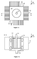
- FIG. 1 a shows a capacitor module according to an exemplifying and non-limiting embodiment of the invention.
- Figure 1b shows a view of a section taken along a line A-A shown in figure 1 a.
- the section plane is parallel with the xz-plane of a coordinate system 190.
- the capacitor module comprises an electrode structure 101 for storing electrical energy in the form of electric charge polarization between electrodes of the electrode structure.
- the electrode structure 101 may comprise e.g. a first foil, a second foil, and dry dielectric material between the first and second foils.
- the electrode structure 101 comprises an anode foil, a cathode foil, and porous filler material between the anode and cathode foils so that the filler material is impregnated with liquid electrolyte.
- the capacitor module is an electrolytic capacitor.
- the electrode structure 101 constitutes an electric double-layer capacitor "EDLC” which is often called a "super capacitor”.
- the capacitor module comprises a casing 102 made of electrically conductive material, e.g. aluminum.
- the casing 102 is a heat-sink element comprising cooling structures and a cavity that contains the electrode structure 101 as illustrated in figure 1b .
- the casing 102 acts not only as a casing but also as a heat-sink element for cooling the electrode structure 101. Furthermore, the casing 102 is a single piece of the electrically conductive material. Thus, the thermally conductive path from the walls of the cavity to the cooling structures is free from mutually interfacing material surfaces. The heat transfer is effective because there are no mutually interfacing material surfaces on the above-mentioned thermally conductive path.
- the cooling structures of the casing 102 may comprise for example cooling fins on an outer surface of the casing and/or cooling channels for conducting liquid or gaseous cooling fluid. Liquid cooling fluid can be e.g. water, and gaseous cooling fluid can be e.g. air.
- one of the cooling fins is denoted with a reference number 104.
- one of the cooling channels is denoted with a reference number 105.
- Connection tubes 108 of the cooling channels are schematically depicted in figure 1 a.
- one of the electrodes of the electrode structure 101 is electrically connected to the casing 102 and the other of the electrodes is electrically connected to a terminal element 107 which is electrically insulated from the casing 102. Therefore, in this case, the casing 102 acts also as an electrical pole of the capacitor module. It is, however, also possible that each of the electrodes of the electrode structure 101 is electrically connected to a respective one of terminal elements which are electrically insulated from each other and from the casing.
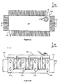
- FIG. 2a shows a capacitor module according to an exemplifying and non-limiting embodiment of the invention.
- Figure 2b shows a view of a section taken along a line A-A shown in figure 2a .
- the section plane is parallel with the xz-plane of a coordinate system 290.
- the capacitor module comprises electrode structures 201 a, 201 b, and 201 c for storing electrical energy.
- Each of the electrode structures 201 a, 201 b, and 201 c may comprise e.g. a first foil, a second foil, and dry dielectric material between the first and second foils.
- each of the electrode structures 201 a, 201 b, and 201 c comprises an anode foil, a cathode foil, and porous filler material between the anode and cathode foils so that the filler material is impregnated with liquid electrolyte.
- the capacitor module is an electrolytic capacitor.
- each of the electrode structures constitutes an electric double-layer capacitor "EDLC”.
- the capacitor module comprises a casing 202 that is a single piece of electrically conductive material, e.g. aluminum.
- the 202 casing is a heat-sink element that comprises cooling structures and cavities that contain the electrode structures 201 a, 201 b, and 201 c as illustrated in figure 2b .
- the cooling structures of the casing 202 may comprise for example cooling fins on an outer surface of the casing and/or cooling channels for conducting liquid or gaseous cooling fluid.
- one of the cooling fins is denoted with a reference number 204.
- one of the cooling channels is denoted with a reference number 205.
- Connection tubes 208 of the cooling channels are schematically depicted in figure 2a . Therefore, the casing 202 acts not only as a casing but also as a heat-sink element for cooling the electrode structures 201 a, 201 b, and 201 c.
- a first one of the electrodes of each of the electrode structures 201 a, 201 b, and 201 c is electrically connected to the casing 202.
- the capacitor module further comprises an electrically conductive lid 206 arranged to close the cavities as illustrated in figure 2b .
- the lid 206 is electrically insulated from the casing 202 with the aid of a layer of electrically insulating material 209.
- a second one of the electrodes of each of the electrode structures 201 a, 201 b, and 201 c is electrically connected to the electrically conductive lid 206. Therefore, the casing 202 constitutes one electrical pole of the capacitor module and the lid 206 constitutes the other electrical pole of the capacitor module.
- the casing 202 can be manufactured as a single piece of electrically conductive material e.g. by casting or extrusion and/or machining. It is, however, also possible that a casing for two or more electrode structures can be constructed by welding together casings each being designed for a single electrode structure.
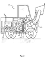
- FIG 3 shows a schematic illustration of a mobile working machine 320 according to an exemplifying and non-limiting embodiment of the invention.
- the mobile working machine is a bucket charger but the mobile working machine could as well be a tractor, a road drag, a bulldozer, or any other working machine having wheels and/or chain tracks or any other means for moving.
- the mobile working machine comprises a combustion engine 321 that can be e.g. a diesel engine, an Otto-cycle engine, or a turbine engine.
- the mobile working machine comprises an electromechanical power transmission chain 322 between the combustion engine 321 and wheels of the mobile working machine.
- the electromechanical transmission chain comprises a generator 321 the rotor of which is mechanically connected to the shaft of the combustion engine.
- the electromechanical transmission chain comprises an electronic power converter 327 and electrical motors at the hubs of the wheels of the mobile working machine.
- two of the electrical motors are denoted with reference numbers 330 and 331.
- the electronic power converter 327 is arranged to convert the electrical voltage produced by the generator 326 into electrical voltages having amplitudes and frequencies suitable for the electrical motors.
- the electromechanical transmission chain further comprises a capacitive energy-storage 323 comprising one or more capacitor modules.
- Each of the capacitor modules comprises one or more electrode structures for storing electrical energy and a casing that is a single piece of electrically conductive material and contains the one or more electrode structures.
- the casing is a heat-sink element that comprises cooling structures, e.g. cooling fins and/or cooling ducts, and one or more cavities containing the one or more electrode structures.
- a mobile working machine comprises a liquid cooling system 324, and the casing of at least one capacitor module comprises cooling ducts connected to the liquid cooling system 324.
- the liquid cooling system 324 can be arranged to cool also the other parts of the electromechanical power transmission chain 322, and/or a hydraulic system 325 of the mobile working machine, and/or the combustion engine 321.
- a mobile working machine comprises a battery element 332 which, together with the capacitive energy-storage 323, can be used for responding to peak power needs exceeding the maximum power of the combustion engine 321.
Landscapes
- Engineering & Computer Science (AREA)
- Power Engineering (AREA)
- Microelectronics & Electronic Packaging (AREA)
- Electric Propulsion And Braking For Vehicles (AREA)
- Hybrid Electric Vehicles (AREA)
- Electric Double-Layer Capacitors Or The Like (AREA)
Priority Applications (2)
| Application Number | Priority Date | Filing Date | Title |
|---|---|---|---|
| EP14170948.5A EP2952377B1 (fr) | 2014-06-03 | 2014-06-03 | Module de condensateur pour machine de travail mobile |
| PCT/FI2015/050363 WO2015185795A1 (fr) | 2014-06-03 | 2015-05-27 | Module de condensateur pour une machine de travail mobile |
Applications Claiming Priority (1)
| Application Number | Priority Date | Filing Date | Title |
|---|---|---|---|
| EP14170948.5A EP2952377B1 (fr) | 2014-06-03 | 2014-06-03 | Module de condensateur pour machine de travail mobile |
Publications (2)
| Publication Number | Publication Date |
|---|---|
| EP2952377A1 true EP2952377A1 (fr) | 2015-12-09 |
| EP2952377B1 EP2952377B1 (fr) | 2017-10-04 |
Family
ID=50841680
Family Applications (1)
| Application Number | Title | Priority Date | Filing Date |
|---|---|---|---|
| EP14170948.5A Not-in-force EP2952377B1 (fr) | 2014-06-03 | 2014-06-03 | Module de condensateur pour machine de travail mobile |
Country Status (2)
| Country | Link |
|---|---|
| EP (1) | EP2952377B1 (fr) |
| WO (1) | WO2015185795A1 (fr) |
Cited By (3)
| Publication number | Priority date | Publication date | Assignee | Title |
|---|---|---|---|---|
| EP3309000A1 (fr) * | 2016-10-12 | 2018-04-18 | Visedo Oy | Module de stockage d'énergie pour un vehicule de chantier |
| EP3486110A1 (fr) * | 2017-11-15 | 2019-05-22 | Danfoss Mobile Electrification Oy | Machine de travail avec accumulateur et avec une batterie et une connexion au réseau électrique |
| EP4158670A4 (fr) * | 2020-06-02 | 2025-04-30 | Fastcap Systems Corporation | Boîtier pour ultracondensateur en forme de puce |
Citations (6)
| Publication number | Priority date | Publication date | Assignee | Title |
|---|---|---|---|---|
| US5214564A (en) * | 1992-04-23 | 1993-05-25 | Sunstrand Corporation | Capacitor assembly with integral cooling apparatus |
| WO1999054893A1 (fr) * | 1998-04-20 | 1999-10-28 | Epcos Ag | Condensateur electrolytique en aluminium |
| DE102005038409A1 (de) * | 2005-08-12 | 2007-03-01 | Epcos Ag | Gehäuse für ein elektrisches Bauelement, Kondensator und Kondensatormodul |
| US20070053156A1 (en) * | 2003-10-31 | 2007-03-08 | Lothar Regenfus | Housing cup for an electronic component with integrated cooling body |
| US20110090614A1 (en) * | 2007-12-06 | 2011-04-21 | Fabien Guerin | Electrical power supply device comprising a tray for accommodating ultra-high capacity storage units |
| EP2682963A1 (fr) * | 2012-07-03 | 2014-01-08 | Visedo Oy | Stockage d'énergie capacitif destiné à une machine de travail mobile |
Family Cites Families (2)
| Publication number | Priority date | Publication date | Assignee | Title |
|---|---|---|---|---|
| JP2002083739A (ja) * | 2000-09-07 | 2002-03-22 | Honda Motor Co Ltd | 電気二重層キャパシタ |
| DE102004043465B4 (de) * | 2004-09-08 | 2007-07-26 | Siemens Ag | Gehäuse für mindestens ein elektronisches Bauteil bestehend aus zwei Gehäusebechern |
-
2014
- 2014-06-03 EP EP14170948.5A patent/EP2952377B1/fr not_active Not-in-force
-
2015
- 2015-05-27 WO PCT/FI2015/050363 patent/WO2015185795A1/fr not_active Ceased
Patent Citations (6)
| Publication number | Priority date | Publication date | Assignee | Title |
|---|---|---|---|---|
| US5214564A (en) * | 1992-04-23 | 1993-05-25 | Sunstrand Corporation | Capacitor assembly with integral cooling apparatus |
| WO1999054893A1 (fr) * | 1998-04-20 | 1999-10-28 | Epcos Ag | Condensateur electrolytique en aluminium |
| US20070053156A1 (en) * | 2003-10-31 | 2007-03-08 | Lothar Regenfus | Housing cup for an electronic component with integrated cooling body |
| DE102005038409A1 (de) * | 2005-08-12 | 2007-03-01 | Epcos Ag | Gehäuse für ein elektrisches Bauelement, Kondensator und Kondensatormodul |
| US20110090614A1 (en) * | 2007-12-06 | 2011-04-21 | Fabien Guerin | Electrical power supply device comprising a tray for accommodating ultra-high capacity storage units |
| EP2682963A1 (fr) * | 2012-07-03 | 2014-01-08 | Visedo Oy | Stockage d'énergie capacitif destiné à une machine de travail mobile |
Cited By (4)
| Publication number | Priority date | Publication date | Assignee | Title |
|---|---|---|---|---|
| EP3309000A1 (fr) * | 2016-10-12 | 2018-04-18 | Visedo Oy | Module de stockage d'énergie pour un vehicule de chantier |
| EP3486110A1 (fr) * | 2017-11-15 | 2019-05-22 | Danfoss Mobile Electrification Oy | Machine de travail avec accumulateur et avec une batterie et une connexion au réseau électrique |
| EP4158670A4 (fr) * | 2020-06-02 | 2025-04-30 | Fastcap Systems Corporation | Boîtier pour ultracondensateur en forme de puce |
| US12315675B2 (en) | 2020-06-02 | 2025-05-27 | Fastcap Ultracapacitors Llc | Housing for chip form ultracapacitor |
Also Published As
| Publication number | Publication date |
|---|---|
| EP2952377B1 (fr) | 2017-10-04 |
| WO2015185795A1 (fr) | 2015-12-10 |
Similar Documents
| Publication | Publication Date | Title |
|---|---|---|
| EP2990253B1 (fr) | Module de condensateur pour machine de travail mobile | |
| CN101300727B (zh) | 驱动系统 | |
| KR20180045838A (ko) | 전지시스템 및 전지시스템과 전기자동차를 위한 베이스플레이트 | |
| KR102840824B1 (ko) | 배터리, 배터리 모듈, 배터리 팩, 및 전기 차량 | |
| WO2010150489A1 (fr) | Unité de stockage électrique | |
| JP2019501477A (ja) | 電気エネルギー蓄電モジュール及びその製造方法 | |
| JP5599344B2 (ja) | 蓄電デバイス | |
| KR20160062447A (ko) | 차량용 인버터의 필름 커패시터 모듈 | |
| US20180301668A1 (en) | An apparatus comprising battery cells and a method of assembling | |
| JP2015069729A (ja) | 蓄電装置 | |
| EP2952377A1 (fr) | Module de condensateur pour machine de travail mobile | |
| DK2735042T3 (en) | ENERGY STORAGE MODULE | |
| CN105304839B (zh) | 具有液体冷却件的电池模块 | |
| CN111033164A (zh) | 热管及具备热管的二次电池 | |
| EP2682963B1 (fr) | Stockage d'énergie capacitif destiné à une machine de travail mobile | |
| JP2012160543A (ja) | 蓄電デバイス | |
| EP3309000B1 (fr) | Module de stockage d'énergie pour un vehicule de chantier | |
| EP3048620A1 (fr) | Module de condensateur pour machine de travail | |
| CN214043864U (zh) | 一种电池组箱 | |
| KR101458600B1 (ko) | 울트라 캐패시터 방열 모듈 | |
| JP2015069724A (ja) | 蓄電装置 | |
| CN111245167B (zh) | 一种一体式电机 | |
| KR102259861B1 (ko) | 울트라 커패시터 및 울트라 커패시터 모듈 | |
| KR20150074144A (ko) | 전기화학 축전셀 | |
| GB2502904A (en) | Hexagonal Shaped Capacitor |
Legal Events
| Date | Code | Title | Description |
|---|---|---|---|
| PUAI | Public reference made under article 153(3) epc to a published international application that has entered the european phase |
Free format text: ORIGINAL CODE: 0009012 |
|
| AK | Designated contracting states |
Kind code of ref document: A1 Designated state(s): AL AT BE BG CH CY CZ DE DK EE ES FI FR GB GR HR HU IE IS IT LI LT LU LV MC MK MT NL NO PL PT RO RS SE SI SK SM TR |
|
| AX | Request for extension of the european patent |
Extension state: BA ME |
|
| 17P | Request for examination filed |
Effective date: 20160531 |
|
| RBV | Designated contracting states (corrected) |
Designated state(s): AL AT BE BG CH CY CZ DE DK EE ES FI FR GB GR HR HU IE IS IT LI LT LU LV MC MK MT NL NO PL PT RO RS SE SI SK SM TR |
|
| 17Q | First examination report despatched |
Effective date: 20160818 |
|
| GRAP | Despatch of communication of intention to grant a patent |
Free format text: ORIGINAL CODE: EPIDOSNIGR1 |
|
| INTG | Intention to grant announced |
Effective date: 20170428 |
|
| GRAA | (expected) grant |
Free format text: ORIGINAL CODE: 0009210 |
|
| GRAS | Grant fee paid |
Free format text: ORIGINAL CODE: EPIDOSNIGR3 |
|
| AK | Designated contracting states |
Kind code of ref document: B1 Designated state(s): AL AT BE BG CH CY CZ DE DK EE ES FI FR GB GR HR HU IE IS IT LI LT LU LV MC MK MT NL NO PL PT RO RS SE SI SK SM TR |
|
| REG | Reference to a national code |
Ref country code: GB Ref legal event code: FG4D |
|
| REG | Reference to a national code |
Ref country code: CH Ref legal event code: EP |
|
| REG | Reference to a national code |
Ref country code: AT Ref legal event code: REF Ref document number: 933664 Country of ref document: AT Kind code of ref document: T Effective date: 20171015 |
|
| REG | Reference to a national code |
Ref country code: IE Ref legal event code: FG4D |
|
| RAP2 | Party data changed (patent owner data changed or rights of a patent transferred) |
Owner name: VISEDO OY |
|
| REG | Reference to a national code |
Ref country code: SE Ref legal event code: TRGR |
|
| REG | Reference to a national code |
Ref country code: DE Ref legal event code: R096 Ref document number: 602014015271 Country of ref document: DE |
|
| REG | Reference to a national code |
Ref country code: NL Ref legal event code: FP |
|
| REG | Reference to a national code |
Ref country code: LT Ref legal event code: MG4D |
|
| REG | Reference to a national code |
Ref country code: AT Ref legal event code: MK05 Ref document number: 933664 Country of ref document: AT Kind code of ref document: T Effective date: 20171004 |
|
| PG25 | Lapsed in a contracting state [announced via postgrant information from national office to epo] |
Ref country code: LT Free format text: LAPSE BECAUSE OF FAILURE TO SUBMIT A TRANSLATION OF THE DESCRIPTION OR TO PAY THE FEE WITHIN THE PRESCRIBED TIME-LIMIT Effective date: 20171004 Ref country code: ES Free format text: LAPSE BECAUSE OF FAILURE TO SUBMIT A TRANSLATION OF THE DESCRIPTION OR TO PAY THE FEE WITHIN THE PRESCRIBED TIME-LIMIT Effective date: 20171004 Ref country code: NO Free format text: LAPSE BECAUSE OF FAILURE TO SUBMIT A TRANSLATION OF THE DESCRIPTION OR TO PAY THE FEE WITHIN THE PRESCRIBED TIME-LIMIT Effective date: 20180104 |
|
| REG | Reference to a national code |
Ref country code: FR Ref legal event code: PLFP Year of fee payment: 5 |
|
| PG25 | Lapsed in a contracting state [announced via postgrant information from national office to epo] |
Ref country code: LV Free format text: LAPSE BECAUSE OF FAILURE TO SUBMIT A TRANSLATION OF THE DESCRIPTION OR TO PAY THE FEE WITHIN THE PRESCRIBED TIME-LIMIT Effective date: 20171004 Ref country code: AT Free format text: LAPSE BECAUSE OF FAILURE TO SUBMIT A TRANSLATION OF THE DESCRIPTION OR TO PAY THE FEE WITHIN THE PRESCRIBED TIME-LIMIT Effective date: 20171004 Ref country code: IS Free format text: LAPSE BECAUSE OF FAILURE TO SUBMIT A TRANSLATION OF THE DESCRIPTION OR TO PAY THE FEE WITHIN THE PRESCRIBED TIME-LIMIT Effective date: 20180204 Ref country code: GR Free format text: LAPSE BECAUSE OF FAILURE TO SUBMIT A TRANSLATION OF THE DESCRIPTION OR TO PAY THE FEE WITHIN THE PRESCRIBED TIME-LIMIT Effective date: 20180105 Ref country code: BG Free format text: LAPSE BECAUSE OF FAILURE TO SUBMIT A TRANSLATION OF THE DESCRIPTION OR TO PAY THE FEE WITHIN THE PRESCRIBED TIME-LIMIT Effective date: 20180104 Ref country code: HR Free format text: LAPSE BECAUSE OF FAILURE TO SUBMIT A TRANSLATION OF THE DESCRIPTION OR TO PAY THE FEE WITHIN THE PRESCRIBED TIME-LIMIT Effective date: 20171004 Ref country code: RS Free format text: LAPSE BECAUSE OF FAILURE TO SUBMIT A TRANSLATION OF THE DESCRIPTION OR TO PAY THE FEE WITHIN THE PRESCRIBED TIME-LIMIT Effective date: 20171004 |
|
| REG | Reference to a national code |
Ref country code: DE Ref legal event code: R097 Ref document number: 602014015271 Country of ref document: DE |
|
| PG25 | Lapsed in a contracting state [announced via postgrant information from national office to epo] |
Ref country code: CZ Free format text: LAPSE BECAUSE OF FAILURE TO SUBMIT A TRANSLATION OF THE DESCRIPTION OR TO PAY THE FEE WITHIN THE PRESCRIBED TIME-LIMIT Effective date: 20171004 Ref country code: SK Free format text: LAPSE BECAUSE OF FAILURE TO SUBMIT A TRANSLATION OF THE DESCRIPTION OR TO PAY THE FEE WITHIN THE PRESCRIBED TIME-LIMIT Effective date: 20171004 Ref country code: DK Free format text: LAPSE BECAUSE OF FAILURE TO SUBMIT A TRANSLATION OF THE DESCRIPTION OR TO PAY THE FEE WITHIN THE PRESCRIBED TIME-LIMIT Effective date: 20171004 Ref country code: EE Free format text: LAPSE BECAUSE OF FAILURE TO SUBMIT A TRANSLATION OF THE DESCRIPTION OR TO PAY THE FEE WITHIN THE PRESCRIBED TIME-LIMIT Effective date: 20171004 |
|
| PLBE | No opposition filed within time limit |
Free format text: ORIGINAL CODE: 0009261 |
|
| STAA | Information on the status of an ep patent application or granted ep patent |
Free format text: STATUS: NO OPPOSITION FILED WITHIN TIME LIMIT |
|
| REG | Reference to a national code |
Ref country code: DE Ref legal event code: R081 Ref document number: 602014015271 Country of ref document: DE Owner name: DANFOSS MOBILE ELECTRIFICATION OY, FI Free format text: FORMER OWNER: VISEDO OY, LAPPEENRANTA, FI |
|
| PG25 | Lapsed in a contracting state [announced via postgrant information from national office to epo] |
Ref country code: RO Free format text: LAPSE BECAUSE OF FAILURE TO SUBMIT A TRANSLATION OF THE DESCRIPTION OR TO PAY THE FEE WITHIN THE PRESCRIBED TIME-LIMIT Effective date: 20171004 Ref country code: PL Free format text: LAPSE BECAUSE OF FAILURE TO SUBMIT A TRANSLATION OF THE DESCRIPTION OR TO PAY THE FEE WITHIN THE PRESCRIBED TIME-LIMIT Effective date: 20171004 Ref country code: SM Free format text: LAPSE BECAUSE OF FAILURE TO SUBMIT A TRANSLATION OF THE DESCRIPTION OR TO PAY THE FEE WITHIN THE PRESCRIBED TIME-LIMIT Effective date: 20171004 |
|
| 26N | No opposition filed |
Effective date: 20180705 |
|
| REG | Reference to a national code |
Ref country code: NL Ref legal event code: HC Owner name: DANFOSS MOBILE ELECTRIFICATION OY; FI Free format text: DETAILS ASSIGNMENT: CHANGE OF OWNER(S), CHANGE OF OWNER(S) NAME; FORMER OWNER NAME: VISEDO OY Effective date: 20180814 |
|
| PG25 | Lapsed in a contracting state [announced via postgrant information from national office to epo] |
Ref country code: SI Free format text: LAPSE BECAUSE OF FAILURE TO SUBMIT A TRANSLATION OF THE DESCRIPTION OR TO PAY THE FEE WITHIN THE PRESCRIBED TIME-LIMIT Effective date: 20171004 |
|
| REG | Reference to a national code |
Ref country code: CH Ref legal event code: PL |
|
| REG | Reference to a national code |
Ref country code: BE Ref legal event code: MM Effective date: 20180630 |
|
| REG | Reference to a national code |
Ref country code: IE Ref legal event code: MM4A |
|
| PG25 | Lapsed in a contracting state [announced via postgrant information from national office to epo] |
Ref country code: LU Free format text: LAPSE BECAUSE OF NON-PAYMENT OF DUE FEES Effective date: 20180603 Ref country code: MC Free format text: LAPSE BECAUSE OF FAILURE TO SUBMIT A TRANSLATION OF THE DESCRIPTION OR TO PAY THE FEE WITHIN THE PRESCRIBED TIME-LIMIT Effective date: 20171004 |
|
| PG25 | Lapsed in a contracting state [announced via postgrant information from national office to epo] |
Ref country code: CH Free format text: LAPSE BECAUSE OF NON-PAYMENT OF DUE FEES Effective date: 20180630 Ref country code: LI Free format text: LAPSE BECAUSE OF NON-PAYMENT OF DUE FEES Effective date: 20180630 Ref country code: IE Free format text: LAPSE BECAUSE OF NON-PAYMENT OF DUE FEES Effective date: 20180603 |
|
| PG25 | Lapsed in a contracting state [announced via postgrant information from national office to epo] |
Ref country code: BE Free format text: LAPSE BECAUSE OF NON-PAYMENT OF DUE FEES Effective date: 20180630 |
|
| PG25 | Lapsed in a contracting state [announced via postgrant information from national office to epo] |
Ref country code: MT Free format text: LAPSE BECAUSE OF NON-PAYMENT OF DUE FEES Effective date: 20180603 |
|
| PG25 | Lapsed in a contracting state [announced via postgrant information from national office to epo] |
Ref country code: TR Free format text: LAPSE BECAUSE OF FAILURE TO SUBMIT A TRANSLATION OF THE DESCRIPTION OR TO PAY THE FEE WITHIN THE PRESCRIBED TIME-LIMIT Effective date: 20171004 |
|
| PG25 | Lapsed in a contracting state [announced via postgrant information from national office to epo] |
Ref country code: PT Free format text: LAPSE BECAUSE OF FAILURE TO SUBMIT A TRANSLATION OF THE DESCRIPTION OR TO PAY THE FEE WITHIN THE PRESCRIBED TIME-LIMIT Effective date: 20171004 |
|
| PG25 | Lapsed in a contracting state [announced via postgrant information from national office to epo] |
Ref country code: MK Free format text: LAPSE BECAUSE OF NON-PAYMENT OF DUE FEES Effective date: 20171004 Ref country code: CY Free format text: LAPSE BECAUSE OF FAILURE TO SUBMIT A TRANSLATION OF THE DESCRIPTION OR TO PAY THE FEE WITHIN THE PRESCRIBED TIME-LIMIT Effective date: 20171004 Ref country code: HU Free format text: LAPSE BECAUSE OF FAILURE TO SUBMIT A TRANSLATION OF THE DESCRIPTION OR TO PAY THE FEE WITHIN THE PRESCRIBED TIME-LIMIT; INVALID AB INITIO Effective date: 20140603 |
|
| PG25 | Lapsed in a contracting state [announced via postgrant information from national office to epo] |
Ref country code: AL Free format text: LAPSE BECAUSE OF FAILURE TO SUBMIT A TRANSLATION OF THE DESCRIPTION OR TO PAY THE FEE WITHIN THE PRESCRIBED TIME-LIMIT Effective date: 20171004 |
|
| P01 | Opt-out of the competence of the unified patent court (upc) registered |
Effective date: 20230617 |
|
| PGFP | Annual fee paid to national office [announced via postgrant information from national office to epo] |
Ref country code: NL Payment date: 20230515 Year of fee payment: 10 Ref country code: IT Payment date: 20230510 Year of fee payment: 10 Ref country code: FR Payment date: 20230523 Year of fee payment: 10 Ref country code: DE Payment date: 20230502 Year of fee payment: 10 |
|
| PGFP | Annual fee paid to national office [announced via postgrant information from national office to epo] |
Ref country code: SE Payment date: 20230510 Year of fee payment: 10 Ref country code: FI Payment date: 20230615 Year of fee payment: 10 |
|
| PGFP | Annual fee paid to national office [announced via postgrant information from national office to epo] |
Ref country code: GB Payment date: 20230504 Year of fee payment: 10 |
|
| REG | Reference to a national code |
Ref country code: FI Ref legal event code: PCE Owner name: DANFOSS A/S |
|
| REG | Reference to a national code |
Ref country code: GB Ref legal event code: 732E Free format text: REGISTERED BETWEEN 20240229 AND 20240306 |
|
| REG | Reference to a national code |
Ref country code: NL Ref legal event code: PD Owner name: DANFOSS A/S; DK Free format text: DETAILS ASSIGNMENT: CHANGE OF OWNER(S), ASSIGNMENT; FORMER OWNER NAME: DANFOSS EDITRON OY Effective date: 20240508 Ref country code: NL Ref legal event code: HC Owner name: DANFOSS EDITRON OY; FI Free format text: DETAILS ASSIGNMENT: CHANGE OF OWNER(S), CHANGE OF OWNER(S) NAME; FORMER OWNER NAME: VISEDO OY Effective date: 20240508 |
|
| REG | Reference to a national code |
Ref country code: DE Ref legal event code: R119 Ref document number: 602014015271 Country of ref document: DE |
|
| PG25 | Lapsed in a contracting state [announced via postgrant information from national office to epo] |
Ref country code: FI Free format text: LAPSE BECAUSE OF NON-PAYMENT OF DUE FEES Effective date: 20240603 |
|
| REG | Reference to a national code |
Ref country code: SE Ref legal event code: EUG |
|
| PG25 | Lapsed in a contracting state [announced via postgrant information from national office to epo] |
Ref country code: FI Free format text: LAPSE BECAUSE OF NON-PAYMENT OF DUE FEES Effective date: 20240603 |
|
| REG | Reference to a national code |
Ref country code: NL Ref legal event code: MM Effective date: 20240701 |
|
| GBPC | Gb: european patent ceased through non-payment of renewal fee |
Effective date: 20240603 |
|
| PG25 | Lapsed in a contracting state [announced via postgrant information from national office to epo] |
Ref country code: NL Free format text: LAPSE BECAUSE OF NON-PAYMENT OF DUE FEES Effective date: 20240701 |
|
| PG25 | Lapsed in a contracting state [announced via postgrant information from national office to epo] |
Ref country code: NL Free format text: LAPSE BECAUSE OF NON-PAYMENT OF DUE FEES Effective date: 20240701 |
|
| PG25 | Lapsed in a contracting state [announced via postgrant information from national office to epo] |
Ref country code: DE Free format text: LAPSE BECAUSE OF NON-PAYMENT OF DUE FEES Effective date: 20250101 |
|
| PG25 | Lapsed in a contracting state [announced via postgrant information from national office to epo] |
Ref country code: FR Free format text: LAPSE BECAUSE OF NON-PAYMENT OF DUE FEES Effective date: 20240630 |
|
| PG25 | Lapsed in a contracting state [announced via postgrant information from national office to epo] |
Ref country code: IT Free format text: LAPSE BECAUSE OF NON-PAYMENT OF DUE FEES Effective date: 20240603 Ref country code: GB Free format text: LAPSE BECAUSE OF NON-PAYMENT OF DUE FEES Effective date: 20240603 |
|
| PG25 | Lapsed in a contracting state [announced via postgrant information from national office to epo] |
Ref country code: SE Free format text: LAPSE BECAUSE OF NON-PAYMENT OF DUE FEES Effective date: 20240604 |