EP2952429B1 - Dispositif de bord de fuite divergent coulissant - Google Patents
Dispositif de bord de fuite divergent coulissant Download PDFInfo
- Publication number
- EP2952429B1 EP2952429B1 EP15165345.8A EP15165345A EP2952429B1 EP 2952429 B1 EP2952429 B1 EP 2952429B1 EP 15165345 A EP15165345 A EP 15165345A EP 2952429 B1 EP2952429 B1 EP 2952429B1
- Authority
- EP
- European Patent Office
- Prior art keywords
- trailing edge
- wing
- divergent
- edge device
- dte
- Prior art date
- Legal status (The legal status is an assumption and is not a legal conclusion. Google has not performed a legal analysis and makes no representation as to the accuracy of the status listed.)
- Active
Links
Images


Classifications
-
- B—PERFORMING OPERATIONS; TRANSPORTING
- B64—AIRCRAFT; AVIATION; COSMONAUTICS
- B64C—AEROPLANES; HELICOPTERS
- B64C9/00—Adjustable control surfaces or members, e.g. rudders
- B64C9/02—Mounting or supporting thereof
-
- B—PERFORMING OPERATIONS; TRANSPORTING
- B64—AIRCRAFT; AVIATION; COSMONAUTICS
- B64C—AEROPLANES; HELICOPTERS
- B64C13/00—Control systems or transmitting systems for actuating flying-control surfaces, lift-increasing flaps, air brakes, or spoilers
- B64C13/24—Transmitting means
-
- B—PERFORMING OPERATIONS; TRANSPORTING
- B64—AIRCRAFT; AVIATION; COSMONAUTICS
- B64C—AEROPLANES; HELICOPTERS
- B64C3/00—Wings
- B64C3/38—Adjustment of complete wings or parts thereof
-
- B—PERFORMING OPERATIONS; TRANSPORTING
- B64—AIRCRAFT; AVIATION; COSMONAUTICS
- B64C—AEROPLANES; HELICOPTERS
- B64C3/00—Wings
- B64C3/38—Adjustment of complete wings or parts thereof
- B64C3/44—Varying camber
- B64C3/50—Varying camber by leading or trailing edge flaps
-
- B—PERFORMING OPERATIONS; TRANSPORTING
- B64—AIRCRAFT; AVIATION; COSMONAUTICS
- B64C—AEROPLANES; HELICOPTERS
- B64C9/00—Adjustable control surfaces or members, e.g. rudders
- B64C9/14—Adjustable control surfaces or members, e.g. rudders forming slots
- B64C9/16—Adjustable control surfaces or members, e.g. rudders forming slots at the rear of the wing
-
- B—PERFORMING OPERATIONS; TRANSPORTING
- B64—AIRCRAFT; AVIATION; COSMONAUTICS
- B64C—AEROPLANES; HELICOPTERS
- B64C3/00—Wings
- B64C3/10—Shape of wings
- B64C3/14—Aerofoil profile
- B64C2003/147—Aerofoil profile comprising trailing edges of particular shape
-
- B—PERFORMING OPERATIONS; TRANSPORTING
- B64—AIRCRAFT; AVIATION; COSMONAUTICS
- B64C—AEROPLANES; HELICOPTERS
- B64C3/00—Wings
- B64C3/28—Leading or trailing edges attached to primary structures, e.g. forming fixed slots
-
- Y—GENERAL TAGGING OF NEW TECHNOLOGICAL DEVELOPMENTS; GENERAL TAGGING OF CROSS-SECTIONAL TECHNOLOGIES SPANNING OVER SEVERAL SECTIONS OF THE IPC; TECHNICAL SUBJECTS COVERED BY FORMER USPC CROSS-REFERENCE ART COLLECTIONS [XRACs] AND DIGESTS
- Y02—TECHNOLOGIES OR APPLICATIONS FOR MITIGATION OR ADAPTATION AGAINST CLIMATE CHANGE
- Y02T—CLIMATE CHANGE MITIGATION TECHNOLOGIES RELATED TO TRANSPORTATION
- Y02T50/00—Aeronautics or air transport
- Y02T50/10—Drag reduction
-
- Y—GENERAL TAGGING OF NEW TECHNOLOGICAL DEVELOPMENTS; GENERAL TAGGING OF CROSS-SECTIONAL TECHNOLOGIES SPANNING OVER SEVERAL SECTIONS OF THE IPC; TECHNICAL SUBJECTS COVERED BY FORMER USPC CROSS-REFERENCE ART COLLECTIONS [XRACs] AND DIGESTS
- Y02—TECHNOLOGIES OR APPLICATIONS FOR MITIGATION OR ADAPTATION AGAINST CLIMATE CHANGE
- Y02T—CLIMATE CHANGE MITIGATION TECHNOLOGIES RELATED TO TRANSPORTATION
- Y02T50/00—Aeronautics or air transport
- Y02T50/30—Wing lift efficiency
-
- Y—GENERAL TAGGING OF NEW TECHNOLOGICAL DEVELOPMENTS; GENERAL TAGGING OF CROSS-SECTIONAL TECHNOLOGIES SPANNING OVER SEVERAL SECTIONS OF THE IPC; TECHNICAL SUBJECTS COVERED BY FORMER USPC CROSS-REFERENCE ART COLLECTIONS [XRACs] AND DIGESTS
- Y02—TECHNOLOGIES OR APPLICATIONS FOR MITIGATION OR ADAPTATION AGAINST CLIMATE CHANGE
- Y02T—CLIMATE CHANGE MITIGATION TECHNOLOGIES RELATED TO TRANSPORTATION
- Y02T50/00—Aeronautics or air transport
- Y02T50/40—Weight reduction
Definitions
- a Divergent Trailing Edge (DTE) device can increase lift over drag (L/D) of a wing.
- the DTE may be fixed to an aft lower surface of a wing.
- a fixed DTE creates a load distribution that can have a significant collateral impact of requiring a stronger, heavier wing.
- a DTE may instead be hinged to an aft lower surface of a wing.
- a hinged DTE may be retracted to a stowed position, and it may be scheduled to extend during the less heavily loaded phases of flight, thus minimizing the collateral structural weight.
- a hinged DTE may be extended and retracted by an actuator and drive linkage.
- the actuator and linkage carry air loads and, therefore, are sized accordingly. If the actuator fails during flight, free surface flutter of the hinged DTE can occur. If the actuator and linkage are too large to fit within the airfoil, they are covered by an external fairing, which adds complexity, weight, and drag.
- EP 1488998 discloses a wing trailing edge.
- US 2012/0261519 discloses a gurney flap.
- a wing comprises a trailing edge, and a divergent trailing edge device slideable along an aft surface of the trailing edge between a stowed position and a fully deployed position.
- the trailing edge device is located entirely within the trailing edge when stowed, and it increases lift over drag of the wing when deployed.
- an aircraft comprises a wing according to the claims, including a trailing edge having a moveable flight control surface and a fixed surface.
- the aircraft further comprises a plurality of divergent trailing edge devices integrated with the moveable flight control surface, and a plurality of actuators for independent control of the divergent trailing edge devices.
- Each divergent trailing edge device is slideable between a stowed position entirely within the moveable flight control surface and a deployed position at least partially under the moveable flight control surface.
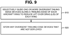
- a method performed during flight of an aircraft comprises sliding a divergent trailing edge device along a trailing edge of each aircraft wing to reduce lift over drag (L/D) of the wing; and thereafter stowing the divergent trailing edge device entirely within the trailing edge.
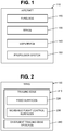
- FIG. 1 illustrates an aircraft 110 including a fuselage 120, wings 130, and empennage 140.
- One or more propulsion units 150 are coupled to the fuselage 120, wings 130 or other portions of the aircraft 110.
- Each wing 130 includes a leading edge and a trailing edge 210.
- the trailing edge 210 may include fixed surfaces 220 and moveable flight control surfaces 230.
- Examples of the moveable flight control surfaces 230 include, but are not limited to, ailerons, flaps, flaperons, and slats.
- the wing 130 further includes at least one divergent trailing edge (DTE) device 240.
- Each DTE device 240 is slideable along an aft surface of the trailing edge 210 between a stowed position and a fully deployed position. When stowed, the DTE device 240 is entirely within the trailing edge 210. When deployed fully or partially, the DTE device 240 extends beneath a lower surface of the trailing edge 210 to increases lift over draft of the wing 130.
- DTE divergent trailing edge
- Chord length of the DTE device 240 may be between about 1% and 6% of chord length of the wing 130. In some configurations, the DTE device 240 may have a chord length between about four and six inches.
- Each DTE device 240 may be mounted to either a fixed surface 220 of the trailing edge 210 or a moveable flight control surface 230 of the trailing edge 210. In some wing configurations, multiple DTE devices 240 may be mounted to a fixed surface 220 and/or a moveable flight control surface 230.
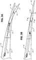
- FIGS. 3A and 3B illustrate an example of a wing 130 including a moveable flight control surface 230 and a DTE device 240 mounted to the moveable flight control surface 230.
- the DTE device 240 includes a stiffened panel 310.
- the stiffened panel 310 is curved. In other configurations, the stiffened panel may be straight (see, e.g., FIG. 7 ).
- the moveable flight control surface 230 also includes a cover 315 for the DTE device 240.
- the cover 315 may also provide a sliding surface for the DTE device 240.
- An actuator assembly 320 may be utilized to slide the trailing edge device 240 between the stowed and deployed positions.
- the actuator assembly 320 may control the DTE device 240 independently of the moveable flight control surface 230.
- the actuator assembly 320 may include an actuator and linkage.
- the actuator assembly 320 may include an actuator alone.
- the actuator may be pneumatic, hydraulic, or electromechanical, and it may be located in a wing box 330 of the wing 130.
- FIG. 3A shows the DTE device 240 in a fully deployed position.
- FIG. 3A shows the DTE device 240 with a maximum divergence angle ( ⁇ ) of about 15 degrees.
- the stiffened panel 310 may have a curvature whereby the divergence angle ( ⁇ ) of the DTE device 240 varies as the DTE device 240 is being deployed. For instance, the DTE device 240 has a maximum divergence angle ( ⁇ ) when fully deployed, and a smaller divergence angle ( ⁇ ) when partially deployed.
- FIG. 3B shows the DTE device 240 in the stowed position.
- the DTE device 240 is located entirely inside the moveable flight control surface 230 and, therefore, does not affect L/D of the wing 130.
- the DTE device 240 may be stowed to avoid exposure to high loading.
- a wing 130 including the DTE device 240 may have lighter wing structures than a wing including a fixed divergent trailing edge device.
- the lighter structures in turn, lead to weight and fuel savings.
- the DTE device 240 offers the same L/D advantage as a fixed divergent trailing edge device.
- the DTE device 240 is slideable instead of hinged, air loads are mostly carried through the wing 130. As a result, the DTE device 240 avoids issues inherent in hinged devices, such as issues with stiffness and torsional loads. The DTE device 240 also avoids free surface and flutter problems in the event the actuator assembly 320 fails.
- the actuator assembly 320 may be configured primarily to overcome friction forces associated with sliding the DTE device 240. As a result, size of the actuator assembly 320 may be reduced to the point where it can be located entirely within the wing box 330.
- a fairing is not used to cover the actuator assembly 320, whereby collateral impact associated with the fairing is avoided.
- FIG. 4 illustrates an example of a trailing edge 210 and a DTE device 240 that is deployed.
- An upper surface 410 of the DTE device 240 is visible.
- the upper surface 410 has a plurality of ribs 420, which extend in a chordwise direction.
- the ribs 420 provide chordwise stiffness of the DTE device 240.
- the ribs 420 of the DTE device 240 make contact with the aft lower surface (not shown) of the trailing edge 210. Upward flight loads on the DTE device 240 are transmitted by the ribs 420 to the trailing edge 210 and are reacted by the wing 130.
- DTE device 240 are interlocked with ribs 350 on an aft lower surface of the trailing edge 210. These interlocked ribs 340 and 350 provide chordwise stiffness and prevent jamming when loads are not uniform spanwise. With these loads paths, the risk of flutter is reduced.
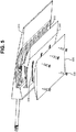
- a cover 520 over a lower surface of the DTE device 240 provides a curved sliding surface for the DTE device 240.
- the cover 520 may also react air loads. For instance, the cover 520 may react a down load on the DTE device 240.
- the cover 520 may be fastened to the trailing edge 210 by fasteners 530.
- the fasteners 530 extend through slots 540 in the DTE device 240 and may limit lateral movement of the DTE device 240.
- a cover 610 may be part of the trailing edge 210.
- the DTE device 240 slides along a surface 622 of a lower portion 620 the trailing edge 210.
- Fasteners 630 fasten the cover 610 to the lower portion 620.
- the fasteners 630 extend through slots 640 in the DTE device 240 and may limit lateral movement of the DTE device 240.
- the DTE devices 240 in FIGS. 3A, 3B , 4 , 5 and 6 are all shown with curved stiffened panels, the DTE device 240 is not so limited.
- the DTE device 240 may include a stiffened panel that is substantially straight
- FIG. 7 illustrates a DTE device 240 that includes a substantially straight stiffened panel 710.
- An actuator assembly 320 including an actuator 720 and an actuator linkage 730 move the DTE device 240 between a stowed position and a fully deployed position.
- the DTE device 240 has a fixed divergence angle ( ⁇ ).
- ⁇ divergence angle
- the DTE device 240 is contained entirely within the trailing edge 210.
- the actuator linkage 730 is along the direction of travel of the DTE device 240, which is mostly normal to the air load direction. Sized to overcome friction forces associated with sliding the DTE device 240, the actuator 720 and the actuator linkage 730 may be located entirely within the trailing edge 210.
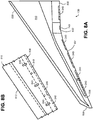
- FIG. 8A illustrates an example of a wing 130 including a wing box 810, a leading edge 820, and a trailing edge 210.
- the trailing edge 210 includes moveable flight control surfaces such as an inboard flap 830, flaperon 832, outboard flap 834, and aileron 836.
- the trailing edge 210 further includes a fixed surface including a tip 838.
- the wing 130 further includes a plurality of DTE devices 240.
- the surfaces 830 to 838 of the trailing edge 210 may include zero, one or multiple DTE devices 240.
- the tip 838 has no DTE devices 240
- the flaperon 832 has a single DTE device 240
- the inboard flap 830 has multiple DTE devices 240
- the outboard flap 834 has multiple DTE devices 240
- the aileron 836 has multiple DTE devices 240.
- DTE devices 240 may be included from the root of the trailing edge 210 all the way out to the tip 838.
- FIG. 8B illustrates a portion of the aileron 836 and a rear spar 812 of the wing box 810.
- Each of the DTE devices 240 may be independently controllable.
- each trailing edge device 240 may be provided with an actuator 840 that is housed with the aileron 836.
Landscapes
- Engineering & Computer Science (AREA)
- Aviation & Aerospace Engineering (AREA)
- Mechanical Engineering (AREA)
- Automation & Control Theory (AREA)
- Toys (AREA)
- Transmission Devices (AREA)
Claims (14)
- Aile comprenant :un bord de fuite (210) ; etun dispositif de bord de fuite divergent (240),caractérisée en ce que le dispositif de bord de fuite divergent (240) peut coulisser le long d'une surface de coulissement du bord de fuite entre une position repliée et une position complètement déployée, le dispositif de bord de fuite divergent (240) étant entièrement situé à l'intérieur du bord de fuite (210) lorsqu'il est replié, le dispositif de bord de fuite divergent (240) s'étend sous une surface inférieure du bord de fuite (210) lorsqu'il est déployé, de manière à augmenter le rapport portance/traînée de l'aile.
- Aile selon la revendication 1, dans laquelle la longueur de corde du dispositif de bord de fuite divergent (240) est comprise entre environ 1 % et 6 % de la longueur de corde de l'aile.
- Aile selon l'une quelconque des revendications 1 et 2, dans laquelle le dispositif de bord de fuite divergent (240) est monté sur une surface de commande de vol mobile (230) du bord de fuite (210).
- Aile selon l'une quelconque des revendications 1 et 2, dans laquelle le dispositif de bord de fuite divergent (240) est monté sur une surface fixe (220) du bord de fuite (210).
- Aile selon l'une quelconque des revendications 1 à 4, dans laquelle le dispositif de bord de fuite divergent (240) a un angle de divergence qui varie lorsque le dispositif est déployé.
- Aile selon l'une quelconque des revendications 1 à 5, comprenant en outre un ensemble d'actionneur contenu entièrement à l'intérieur du bord de fuite (210) pour faire coulisser le dispositif de bord de fuite divergent (240).
- Aile selon l'une quelconque des revendications 1 à 6, dans laquelle le dispositif de bord de fuite divergent (240) comprend un panneau courbé renforcé (310).
- Aile selon l'une quelconque des revendications 1 à 6, dans laquelle le dispositif de bord de fuite divergent (240) comprend un panneau renforcé (310) qui est sensiblement rectiligne.
- Aile selon l'une quelconque des revendications 1 à 8, dans laquelle une surface supérieure du dispositif de bord de fuite divergent (240) comprend des nervures (420) qui entrent en contact avec une surface inférieure arrière du bord de fuite (210).
- Aile selon la revendication 9, dans laquelle la surface inférieure arrière du bord de fuite (210) comporte également des nervures (510), qui s'emboîtent avec les nervures (420) du dispositif de bord de fuite divergent (240) .
- Aile selon l'une quelconque des revendications 1 à 10, comprenant en outre un capot (520) sur une surface inférieure du dispositif de bord de fuite divergent (240), le capot (520) fournissant la surface de coulissement pour le dispositif de bord de fuite divergent (240).
- Aile selon l'une quelconque des revendications 1 à 10, dans laquelle le bord de fuite (210) comprend un capot (315) sur une surface supérieure du dispositif de bord de fuite divergent (240).
- Aile selon l'une quelconque des revendications 1 à 12, comprenant en outre au moins un dispositif de bord de fuite divergent supplémentaire pouvant coulisser le long de la surface de coulissement du bord de fuite (310), chaque dispositif de bord de fuite divergent supplémentaire pouvant coulisser entre une position repliée et une position déployée et une pluralité d'actionneurs pour une commande indépendante de chaque dispositif de bord de fuite divergent (240).
- Procédé exécuté pendant le vol d'un avion (110), le procédé consistant à faire coulisser un dispositif de bord de fuite divergent le long d'une surface de coulissement d'un bord de fuite (210) de chaque aile d'avion pour réduire le rapport portance/traînée (L/D) de l'aile ; et ensuite à replier le dispositif de bord de fuite divergent (240) entièrement à l'intérieur du bord de fuite (210).
Priority Applications (1)
| Application Number | Priority Date | Filing Date | Title |
|---|---|---|---|
| EP18175169.4A EP3388331B1 (fr) | 2014-06-06 | 2015-04-28 | Dispositif de bord de fuite divergent coulissant |
Applications Claiming Priority (1)
| Application Number | Priority Date | Filing Date | Title |
|---|---|---|---|
| US14/298,105 US9463869B2 (en) | 2014-06-06 | 2014-06-06 | Slidable divergent trailing edge device |
Related Child Applications (2)
| Application Number | Title | Priority Date | Filing Date |
|---|---|---|---|
| EP18175169.4A Division EP3388331B1 (fr) | 2014-06-06 | 2015-04-28 | Dispositif de bord de fuite divergent coulissant |
| EP18175169.4A Division-Into EP3388331B1 (fr) | 2014-06-06 | 2015-04-28 | Dispositif de bord de fuite divergent coulissant |
Publications (2)
| Publication Number | Publication Date |
|---|---|
| EP2952429A1 EP2952429A1 (fr) | 2015-12-09 |
| EP2952429B1 true EP2952429B1 (fr) | 2018-08-01 |
Family
ID=53016511
Family Applications (2)
| Application Number | Title | Priority Date | Filing Date |
|---|---|---|---|
| EP18175169.4A Active EP3388331B1 (fr) | 2014-06-06 | 2015-04-28 | Dispositif de bord de fuite divergent coulissant |
| EP15165345.8A Active EP2952429B1 (fr) | 2014-06-06 | 2015-04-28 | Dispositif de bord de fuite divergent coulissant |
Family Applications Before (1)
| Application Number | Title | Priority Date | Filing Date |
|---|---|---|---|
| EP18175169.4A Active EP3388331B1 (fr) | 2014-06-06 | 2015-04-28 | Dispositif de bord de fuite divergent coulissant |
Country Status (5)
| Country | Link |
|---|---|
| US (1) | US9463869B2 (fr) |
| EP (2) | EP3388331B1 (fr) |
| CN (1) | CN105173062B (fr) |
| CA (1) | CA2884527C (fr) |
| ES (2) | ES2773598T3 (fr) |
Families Citing this family (9)
| Publication number | Priority date | Publication date | Assignee | Title |
|---|---|---|---|---|
| WO2017151580A1 (fr) * | 2016-02-29 | 2017-09-08 | Flexsys, Inc. | Agencement de morphage de bord destiné à une surface portante |
| WO2018005534A1 (fr) * | 2016-06-30 | 2018-01-04 | Bombardier Inc. | Ensembles et procédés de déploiement d'un volet de bord de fuite d'un aéronef |
| CN106314760A (zh) * | 2016-09-23 | 2017-01-11 | 南昌航空大学 | 一种内腔通流式高气动效率翼型 |
| CN107444612B (zh) * | 2017-08-15 | 2023-04-18 | 中国空气动力研究与发展中心高速空气动力研究所 | 一种λ机翼飞翼布局无人飞行器的变机翼前缘装置 |
| US10640196B1 (en) * | 2017-09-05 | 2020-05-05 | Northrop Grumman Systems Corporation | Aircraft blade seal |
| WO2020059896A1 (fr) * | 2018-09-17 | 2020-03-26 | 한국항공대학교산학협력단 | Pale transformable |
| CN109484625A (zh) * | 2019-01-02 | 2019-03-19 | 南昌航空大学 | 一种机翼刚度可变的飞行器 |
| CN112498661B (zh) * | 2020-12-04 | 2024-01-30 | 中国航空工业集团公司沈阳飞机设计研究所 | 一种多功能舵面结构 |
| CN114671009A (zh) * | 2022-04-13 | 2022-06-28 | 彩虹无人机科技有限公司 | 一种无人机用内埋式副翼操纵机构及无人机 |
Family Cites Families (25)
| Publication number | Priority date | Publication date | Assignee | Title |
|---|---|---|---|---|
| US240495A (en) | 1881-04-26 | Horse hay-rake | ||
| US2147360A (en) | 1933-02-16 | 1939-02-14 | Zap Dev Corp | Airplane control apparatus |
| US2306015A (en) * | 1938-03-25 | 1942-12-22 | Dornier Claude | Wing structure for aircraft |
| US2271226A (en) * | 1938-10-31 | 1942-01-27 | Lockheed Aircraft Corp | Airplane |
| US2405726A (en) * | 1940-08-14 | 1946-08-13 | Edward F Zap | Airplane wing construction |
| US2791385A (en) | 1952-03-10 | 1957-05-07 | Lockheed Aircraft Corp | Landing drag flap and lift spoiler |
| US3076623A (en) | 1960-10-19 | 1963-02-05 | Donald G Lyon | Variable shaped airfoil |
| US3617018A (en) * | 1970-01-26 | 1971-11-02 | Boeing Co | Folding flap |
| US4460138A (en) * | 1982-09-29 | 1984-07-17 | Sankrithi Mithra M K V | Flexible flap for an airfoil |
| US4614320A (en) * | 1984-03-27 | 1986-09-30 | Rutan Elbert L | Aircraft wing flap |
| US4858852A (en) | 1987-06-01 | 1989-08-22 | Mcdonnell Douglas Corporation | Divergent trailing-edge airfoil |
| FR2792285B1 (fr) | 1999-04-16 | 2001-06-08 | Onera (Off Nat Aerospatiale) | Surface aerodynamique d'aeronef a deflecteur de bord de fuite |
| DE10147827A1 (de) | 2001-09-27 | 2003-04-24 | Airbus Gmbh | Vorrichtung zur Änderung der Quertriebsgröße eines Flugzeughauptelementes mit vorzugsweise flächenförmiger Hinterkante |
| US6843452B1 (en) | 2003-06-17 | 2005-01-18 | The Boeing Company | Variable trailing edge geometry and spanload control |
| US7475848B2 (en) * | 2003-11-11 | 2009-01-13 | Morgenstern John M | Wing employing leading edge flaps and winglets to achieve improved aerodynamic performance |
| DE102005061751B4 (de) * | 2005-12-21 | 2013-09-19 | Eurocopter Deutschland Gmbh | Rotorblatt für ein Drehflügelflugzeug |
| US7878459B2 (en) * | 2007-06-29 | 2011-02-01 | The Boeing Company | Aircraft systems with shape memory alloy (SMA) actuators, and associated methods |
| GB0722415D0 (en) * | 2007-11-15 | 2007-12-27 | Airbus Uk Ltd | Aircraft wing and flap deployment system |
| US7997538B2 (en) * | 2008-03-13 | 2011-08-16 | The Boeing Company | Aerodynamic fan control effector |
| US8684690B2 (en) * | 2009-05-26 | 2014-04-01 | Agustawestland North America, Inc | Variable chord morphing helicopter rotor |
| GB0921007D0 (en) * | 2009-11-30 | 2010-01-13 | Airbus Operations Ltd | Trailing edge flap |
| EP2514667B1 (fr) | 2011-04-18 | 2015-06-10 | Claverham Limited | Volet de Gurney actif |
| US20120280089A1 (en) * | 2011-05-02 | 2012-11-08 | Douglas Otto Keller | Double Slotted Flap for Small Airplane |
| US8438743B2 (en) * | 2011-06-01 | 2013-05-14 | Hamilton Sundstrand Corporation | Resolver type skew sensor with gimbal attachment |
| CN202213712U (zh) * | 2011-09-02 | 2012-05-09 | 北京航空航天大学 | 一种双通道干线客机前缘缝翼驱动机构 |
-
2014
- 2014-06-06 US US14/298,105 patent/US9463869B2/en active Active
-
2015
- 2015-03-09 CA CA2884527A patent/CA2884527C/fr active Active
- 2015-04-28 ES ES18175169T patent/ES2773598T3/es active Active
- 2015-04-28 ES ES15165345.8T patent/ES2693395T3/es active Active
- 2015-04-28 EP EP18175169.4A patent/EP3388331B1/fr active Active
- 2015-04-28 EP EP15165345.8A patent/EP2952429B1/fr active Active
- 2015-06-08 CN CN201510312427.XA patent/CN105173062B/zh active Active
Also Published As
| Publication number | Publication date |
|---|---|
| EP3388331B1 (fr) | 2019-12-04 |
| CN105173062A (zh) | 2015-12-23 |
| ES2773598T3 (es) | 2020-07-13 |
| CN105173062B (zh) | 2018-09-21 |
| EP2952429A1 (fr) | 2015-12-09 |
| EP3388331A1 (fr) | 2018-10-17 |
| CA2884527A1 (fr) | 2015-12-06 |
| ES2693395T3 (es) | 2018-12-11 |
| US9463869B2 (en) | 2016-10-11 |
| US20150353188A1 (en) | 2015-12-10 |
| CA2884527C (fr) | 2017-03-07 |
Similar Documents
| Publication | Publication Date | Title |
|---|---|---|
| EP2952429B1 (fr) | Dispositif de bord de fuite divergent coulissant | |
| US10710702B2 (en) | Shape adaptive airfoil | |
| CN101309832B (zh) | 飞行器后缘设备,含运动路径非平行的设备,和有关方法 | |
| EP3034393B1 (fr) | Dispositif de bord de fuite avec mécanisme à levier coudé | |
| EP2727826B1 (fr) | Ailette d'extrémité de voilure articulée | |
| US11845350B2 (en) | Energy-harvesting spoiler on a wing of an aircraft | |
| US20130099060A1 (en) | Hinged Raked Wing Tip | |
| US8622350B1 (en) | Compound leading edge device for aircraft | |
| US8262017B2 (en) | Aircraft with forward lifting elevator and rudder, with the main lifting surface aft, containing ailerons and flaps, and airbrake | |
| EP2727827B1 (fr) | Bout de l'aile pliable de manière horizontale | |
| EP4400414B1 (fr) | Volets pliants de bord de fuite montés en sous-aile pour ailes d'aéronef | |
| WO2025136750A9 (fr) | Machine et appareil pour aéronef à voilure fixe à décollage et atterrissage ultra-courts | |
| US8651429B2 (en) | Blended cutout flap for reduction of jet-flap interaction noise | |
| Pfeiffer | Slotted airfoil with control surface | |
| US12269593B2 (en) | Wing assemblies and aircraft | |
| US12043386B2 (en) | Wing assemblies and aircraft | |
| EP2797812B1 (fr) | Avion subsonique ou simulateur de vol correspondant, surface de commande de fuselage réglable, progiciel et procédé |
Legal Events
| Date | Code | Title | Description |
|---|---|---|---|
| PUAI | Public reference made under article 153(3) epc to a published international application that has entered the european phase |
Free format text: ORIGINAL CODE: 0009012 |
|
| 17P | Request for examination filed |
Effective date: 20150428 |
|
| AK | Designated contracting states |
Kind code of ref document: A1 Designated state(s): AL AT BE BG CH CY CZ DE DK EE ES FI FR GB GR HR HU IE IS IT LI LT LU LV MC MK MT NL NO PL PT RO RS SE SI SK SM TR |
|
| AX | Request for extension of the european patent |
Extension state: BA ME |
|
| 17Q | First examination report despatched |
Effective date: 20160729 |
|
| STAA | Information on the status of an ep patent application or granted ep patent |
Free format text: STATUS: EXAMINATION IS IN PROGRESS |
|
| REG | Reference to a national code |
Ref country code: DE Ref legal event code: R079 Ref document number: 602015014180 Country of ref document: DE Free format text: PREVIOUS MAIN CLASS: B64C0003380000 Ipc: B64C0009020000 |
|
| GRAP | Despatch of communication of intention to grant a patent |
Free format text: ORIGINAL CODE: EPIDOSNIGR1 |
|
| STAA | Information on the status of an ep patent application or granted ep patent |
Free format text: STATUS: GRANT OF PATENT IS INTENDED |
|
| RIC1 | Information provided on ipc code assigned before grant |
Ipc: B64C 9/16 20060101ALI20180201BHEP Ipc: B64C 9/02 20060101AFI20180201BHEP |
|
| INTG | Intention to grant announced |
Effective date: 20180220 |
|
| GRAS | Grant fee paid |
Free format text: ORIGINAL CODE: EPIDOSNIGR3 |
|
| GRAA | (expected) grant |
Free format text: ORIGINAL CODE: 0009210 |
|
| STAA | Information on the status of an ep patent application or granted ep patent |
Free format text: STATUS: THE PATENT HAS BEEN GRANTED |
|
| AK | Designated contracting states |
Kind code of ref document: B1 Designated state(s): AL AT BE BG CH CY CZ DE DK EE ES FI FR GB GR HR HU IE IS IT LI LT LU LV MC MK MT NL NO PL PT RO RS SE SI SK SM TR |
|
| REG | Reference to a national code |
Ref country code: GB Ref legal event code: FG4D |
|
| REG | Reference to a national code |
Ref country code: CH Ref legal event code: EP Ref country code: AT Ref legal event code: REF Ref document number: 1023971 Country of ref document: AT Kind code of ref document: T Effective date: 20180815 |
|
| REG | Reference to a national code |
Ref country code: IE Ref legal event code: FG4D |
|
| REG | Reference to a national code |
Ref country code: DE Ref legal event code: R096 Ref document number: 602015014180 Country of ref document: DE |
|
| REG | Reference to a national code |
Ref country code: NL Ref legal event code: MP Effective date: 20180801 |
|
| REG | Reference to a national code |
Ref country code: ES Ref legal event code: FG2A Ref document number: 2693395 Country of ref document: ES Kind code of ref document: T3 Effective date: 20181211 |
|
| REG | Reference to a national code |
Ref country code: LT Ref legal event code: MG4D |
|
| REG | Reference to a national code |
Ref country code: AT Ref legal event code: MK05 Ref document number: 1023971 Country of ref document: AT Kind code of ref document: T Effective date: 20180801 |
|
| PG25 | Lapsed in a contracting state [announced via postgrant information from national office to epo] |
Ref country code: FI Free format text: LAPSE BECAUSE OF FAILURE TO SUBMIT A TRANSLATION OF THE DESCRIPTION OR TO PAY THE FEE WITHIN THE PRESCRIBED TIME-LIMIT Effective date: 20180801 Ref country code: PL Free format text: LAPSE BECAUSE OF FAILURE TO SUBMIT A TRANSLATION OF THE DESCRIPTION OR TO PAY THE FEE WITHIN THE PRESCRIBED TIME-LIMIT Effective date: 20180801 Ref country code: LT Free format text: LAPSE BECAUSE OF FAILURE TO SUBMIT A TRANSLATION OF THE DESCRIPTION OR TO PAY THE FEE WITHIN THE PRESCRIBED TIME-LIMIT Effective date: 20180801 Ref country code: GR Free format text: LAPSE BECAUSE OF FAILURE TO SUBMIT A TRANSLATION OF THE DESCRIPTION OR TO PAY THE FEE WITHIN THE PRESCRIBED TIME-LIMIT Effective date: 20181102 Ref country code: SE Free format text: LAPSE BECAUSE OF FAILURE TO SUBMIT A TRANSLATION OF THE DESCRIPTION OR TO PAY THE FEE WITHIN THE PRESCRIBED TIME-LIMIT Effective date: 20180801 Ref country code: NL Free format text: LAPSE BECAUSE OF FAILURE TO SUBMIT A TRANSLATION OF THE DESCRIPTION OR TO PAY THE FEE WITHIN THE PRESCRIBED TIME-LIMIT Effective date: 20180801 Ref country code: BG Free format text: LAPSE BECAUSE OF FAILURE TO SUBMIT A TRANSLATION OF THE DESCRIPTION OR TO PAY THE FEE WITHIN THE PRESCRIBED TIME-LIMIT Effective date: 20181101 Ref country code: IS Free format text: LAPSE BECAUSE OF FAILURE TO SUBMIT A TRANSLATION OF THE DESCRIPTION OR TO PAY THE FEE WITHIN THE PRESCRIBED TIME-LIMIT Effective date: 20181201 Ref country code: RS Free format text: LAPSE BECAUSE OF FAILURE TO SUBMIT A TRANSLATION OF THE DESCRIPTION OR TO PAY THE FEE WITHIN THE PRESCRIBED TIME-LIMIT Effective date: 20180801 Ref country code: AT Free format text: LAPSE BECAUSE OF FAILURE TO SUBMIT A TRANSLATION OF THE DESCRIPTION OR TO PAY THE FEE WITHIN THE PRESCRIBED TIME-LIMIT Effective date: 20180801 Ref country code: NO Free format text: LAPSE BECAUSE OF FAILURE TO SUBMIT A TRANSLATION OF THE DESCRIPTION OR TO PAY THE FEE WITHIN THE PRESCRIBED TIME-LIMIT Effective date: 20181101 |
|
| PG25 | Lapsed in a contracting state [announced via postgrant information from national office to epo] |
Ref country code: HR Free format text: LAPSE BECAUSE OF FAILURE TO SUBMIT A TRANSLATION OF THE DESCRIPTION OR TO PAY THE FEE WITHIN THE PRESCRIBED TIME-LIMIT Effective date: 20180801 Ref country code: AL Free format text: LAPSE BECAUSE OF FAILURE TO SUBMIT A TRANSLATION OF THE DESCRIPTION OR TO PAY THE FEE WITHIN THE PRESCRIBED TIME-LIMIT Effective date: 20180801 Ref country code: LV Free format text: LAPSE BECAUSE OF FAILURE TO SUBMIT A TRANSLATION OF THE DESCRIPTION OR TO PAY THE FEE WITHIN THE PRESCRIBED TIME-LIMIT Effective date: 20180801 |
|
| PG25 | Lapsed in a contracting state [announced via postgrant information from national office to epo] |
Ref country code: CZ Free format text: LAPSE BECAUSE OF FAILURE TO SUBMIT A TRANSLATION OF THE DESCRIPTION OR TO PAY THE FEE WITHIN THE PRESCRIBED TIME-LIMIT Effective date: 20180801 Ref country code: RO Free format text: LAPSE BECAUSE OF FAILURE TO SUBMIT A TRANSLATION OF THE DESCRIPTION OR TO PAY THE FEE WITHIN THE PRESCRIBED TIME-LIMIT Effective date: 20180801 Ref country code: EE Free format text: LAPSE BECAUSE OF FAILURE TO SUBMIT A TRANSLATION OF THE DESCRIPTION OR TO PAY THE FEE WITHIN THE PRESCRIBED TIME-LIMIT Effective date: 20180801 |
|
| REG | Reference to a national code |
Ref country code: DE Ref legal event code: R097 Ref document number: 602015014180 Country of ref document: DE |
|
| PG25 | Lapsed in a contracting state [announced via postgrant information from national office to epo] |
Ref country code: DK Free format text: LAPSE BECAUSE OF FAILURE TO SUBMIT A TRANSLATION OF THE DESCRIPTION OR TO PAY THE FEE WITHIN THE PRESCRIBED TIME-LIMIT Effective date: 20180801 Ref country code: SK Free format text: LAPSE BECAUSE OF FAILURE TO SUBMIT A TRANSLATION OF THE DESCRIPTION OR TO PAY THE FEE WITHIN THE PRESCRIBED TIME-LIMIT Effective date: 20180801 Ref country code: SM Free format text: LAPSE BECAUSE OF FAILURE TO SUBMIT A TRANSLATION OF THE DESCRIPTION OR TO PAY THE FEE WITHIN THE PRESCRIBED TIME-LIMIT Effective date: 20180801 |
|
| PLBE | No opposition filed within time limit |
Free format text: ORIGINAL CODE: 0009261 |
|
| STAA | Information on the status of an ep patent application or granted ep patent |
Free format text: STATUS: NO OPPOSITION FILED WITHIN TIME LIMIT |
|
| 26N | No opposition filed |
Effective date: 20190503 |
|
| PG25 | Lapsed in a contracting state [announced via postgrant information from national office to epo] |
Ref country code: SI Free format text: LAPSE BECAUSE OF FAILURE TO SUBMIT A TRANSLATION OF THE DESCRIPTION OR TO PAY THE FEE WITHIN THE PRESCRIBED TIME-LIMIT Effective date: 20180801 |
|
| REG | Reference to a national code |
Ref country code: CH Ref legal event code: PL |
|
| REG | Reference to a national code |
Ref country code: BE Ref legal event code: MM Effective date: 20190430 |
|
| PG25 | Lapsed in a contracting state [announced via postgrant information from national office to epo] |
Ref country code: LU Free format text: LAPSE BECAUSE OF NON-PAYMENT OF DUE FEES Effective date: 20190428 Ref country code: MC Free format text: LAPSE BECAUSE OF FAILURE TO SUBMIT A TRANSLATION OF THE DESCRIPTION OR TO PAY THE FEE WITHIN THE PRESCRIBED TIME-LIMIT Effective date: 20180801 |
|
| REG | Reference to a national code |
Ref country code: DE Ref legal event code: R082 Ref document number: 602015014180 Country of ref document: DE Representative=s name: MAIER, LL.M., MICHAEL C., DE Ref country code: DE Ref legal event code: R082 Ref document number: 602015014180 Country of ref document: DE Representative=s name: BOULT WADE TENNANT LLP, DE |
|
| PG25 | Lapsed in a contracting state [announced via postgrant information from national office to epo] |
Ref country code: CH Free format text: LAPSE BECAUSE OF NON-PAYMENT OF DUE FEES Effective date: 20190430 Ref country code: LI Free format text: LAPSE BECAUSE OF NON-PAYMENT OF DUE FEES Effective date: 20190430 |
|
| REG | Reference to a national code |
Ref country code: DE Ref legal event code: R082 Ref document number: 602015014180 Country of ref document: DE Representative=s name: BOULT WADE TENNANT LLP, DE |
|
| PG25 | Lapsed in a contracting state [announced via postgrant information from national office to epo] |
Ref country code: BE Free format text: LAPSE BECAUSE OF NON-PAYMENT OF DUE FEES Effective date: 20190430 |
|
| PG25 | Lapsed in a contracting state [announced via postgrant information from national office to epo] |
Ref country code: TR Free format text: LAPSE BECAUSE OF FAILURE TO SUBMIT A TRANSLATION OF THE DESCRIPTION OR TO PAY THE FEE WITHIN THE PRESCRIBED TIME-LIMIT Effective date: 20180801 |
|
| PG25 | Lapsed in a contracting state [announced via postgrant information from national office to epo] |
Ref country code: IE Free format text: LAPSE BECAUSE OF NON-PAYMENT OF DUE FEES Effective date: 20190428 |
|
| PG25 | Lapsed in a contracting state [announced via postgrant information from national office to epo] |
Ref country code: PT Free format text: LAPSE BECAUSE OF FAILURE TO SUBMIT A TRANSLATION OF THE DESCRIPTION OR TO PAY THE FEE WITHIN THE PRESCRIBED TIME-LIMIT Effective date: 20181201 |
|
| PG25 | Lapsed in a contracting state [announced via postgrant information from national office to epo] |
Ref country code: CY Free format text: LAPSE BECAUSE OF FAILURE TO SUBMIT A TRANSLATION OF THE DESCRIPTION OR TO PAY THE FEE WITHIN THE PRESCRIBED TIME-LIMIT Effective date: 20180801 |
|
| PG25 | Lapsed in a contracting state [announced via postgrant information from national office to epo] |
Ref country code: MT Free format text: LAPSE BECAUSE OF FAILURE TO SUBMIT A TRANSLATION OF THE DESCRIPTION OR TO PAY THE FEE WITHIN THE PRESCRIBED TIME-LIMIT Effective date: 20180801 Ref country code: HU Free format text: LAPSE BECAUSE OF FAILURE TO SUBMIT A TRANSLATION OF THE DESCRIPTION OR TO PAY THE FEE WITHIN THE PRESCRIBED TIME-LIMIT; INVALID AB INITIO Effective date: 20150428 |
|
| PG25 | Lapsed in a contracting state [announced via postgrant information from national office to epo] |
Ref country code: MK Free format text: LAPSE BECAUSE OF FAILURE TO SUBMIT A TRANSLATION OF THE DESCRIPTION OR TO PAY THE FEE WITHIN THE PRESCRIBED TIME-LIMIT Effective date: 20180801 |
|
| P01 | Opt-out of the competence of the unified patent court (upc) registered |
Effective date: 20230516 |
|
| PGFP | Annual fee paid to national office [announced via postgrant information from national office to epo] |
Ref country code: DE Payment date: 20250429 Year of fee payment: 11 |
|
| PGFP | Annual fee paid to national office [announced via postgrant information from national office to epo] |
Ref country code: GB Payment date: 20250428 Year of fee payment: 11 Ref country code: ES Payment date: 20250505 Year of fee payment: 11 |
|
| PGFP | Annual fee paid to national office [announced via postgrant information from national office to epo] |
Ref country code: IT Payment date: 20250422 Year of fee payment: 11 |
|
| PGFP | Annual fee paid to national office [announced via postgrant information from national office to epo] |
Ref country code: FR Payment date: 20250425 Year of fee payment: 11 |