EP2952440A1 - Corps de réception, dispositif de retenue et corps composite de réception - Google Patents
Corps de réception, dispositif de retenue et corps composite de réception Download PDFInfo
- Publication number
- EP2952440A1 EP2952440A1 EP15166236.8A EP15166236A EP2952440A1 EP 2952440 A1 EP2952440 A1 EP 2952440A1 EP 15166236 A EP15166236 A EP 15166236A EP 2952440 A1 EP2952440 A1 EP 2952440A1
- Authority
- EP
- European Patent Office
- Prior art keywords
- receiving
- receiving body
- bodies
- space
- webs
- Prior art date
- Legal status (The legal status is an assumption and is not a legal conclusion. Google has not performed a legal analysis and makes no representation as to the accuracy of the status listed.)
- Granted
Links
Images


Classifications
-
- B—PERFORMING OPERATIONS; TRANSPORTING
- B65—CONVEYING; PACKING; STORING; HANDLING THIN OR FILAMENTARY MATERIAL
- B65D—CONTAINERS FOR STORAGE OR TRANSPORT OF ARTICLES OR MATERIALS, e.g. BAGS, BARRELS, BOTTLES, BOXES, CANS, CARTONS, CRATES, DRUMS, JARS, TANKS, HOPPERS, FORWARDING CONTAINERS; ACCESSORIES, CLOSURES, OR FITTINGS THEREFOR; PACKAGING ELEMENTS; PACKAGES
- B65D19/00—Pallets or like platforms, with or without side walls, for supporting loads to be lifted or lowered
- B65D19/0002—Platforms, i.e. load supporting devices without provision for handling by a forklift
-
- B—PERFORMING OPERATIONS; TRANSPORTING
- B65—CONVEYING; PACKING; STORING; HANDLING THIN OR FILAMENTARY MATERIAL
- B65D—CONTAINERS FOR STORAGE OR TRANSPORT OF ARTICLES OR MATERIALS, e.g. BAGS, BARRELS, BOTTLES, BOXES, CANS, CARTONS, CRATES, DRUMS, JARS, TANKS, HOPPERS, FORWARDING CONTAINERS; ACCESSORIES, CLOSURES, OR FITTINGS THEREFOR; PACKAGING ELEMENTS; PACKAGES
- B65D19/00—Pallets or like platforms, with or without side walls, for supporting loads to be lifted or lowered
- B65D19/38—Details or accessories
- B65D19/385—Frames, corner posts or pallet converters, e.g. for facilitating stacking of charged pallets
-
- B—PERFORMING OPERATIONS; TRANSPORTING
- B65—CONVEYING; PACKING; STORING; HANDLING THIN OR FILAMENTARY MATERIAL
- B65D—CONTAINERS FOR STORAGE OR TRANSPORT OF ARTICLES OR MATERIALS, e.g. BAGS, BARRELS, BOTTLES, BOXES, CANS, CARTONS, CRATES, DRUMS, JARS, TANKS, HOPPERS, FORWARDING CONTAINERS; ACCESSORIES, CLOSURES, OR FITTINGS THEREFOR; PACKAGING ELEMENTS; PACKAGES
- B65D19/00—Pallets or like platforms, with or without side walls, for supporting loads to be lifted or lowered
- B65D19/38—Details or accessories
- B65D19/44—Elements or devices for locating articles on platforms
-
- B—PERFORMING OPERATIONS; TRANSPORTING
- B65—CONVEYING; PACKING; STORING; HANDLING THIN OR FILAMENTARY MATERIAL
- B65D—CONTAINERS FOR STORAGE OR TRANSPORT OF ARTICLES OR MATERIALS, e.g. BAGS, BARRELS, BOTTLES, BOXES, CANS, CARTONS, CRATES, DRUMS, JARS, TANKS, HOPPERS, FORWARDING CONTAINERS; ACCESSORIES, CLOSURES, OR FITTINGS THEREFOR; PACKAGING ELEMENTS; PACKAGES
- B65D2519/00—Pallets or like platforms, with or without side walls, for supporting loads to be lifted or lowered
- B65D2519/00004—Details relating to pallets
- B65D2519/00009—Materials
- B65D2519/00014—Materials for the load supporting surface
- B65D2519/00024—Metal
-
- B—PERFORMING OPERATIONS; TRANSPORTING
- B65—CONVEYING; PACKING; STORING; HANDLING THIN OR FILAMENTARY MATERIAL
- B65D—CONTAINERS FOR STORAGE OR TRANSPORT OF ARTICLES OR MATERIALS, e.g. BAGS, BARRELS, BOTTLES, BOXES, CANS, CARTONS, CRATES, DRUMS, JARS, TANKS, HOPPERS, FORWARDING CONTAINERS; ACCESSORIES, CLOSURES, OR FITTINGS THEREFOR; PACKAGING ELEMENTS; PACKAGES
- B65D2519/00—Pallets or like platforms, with or without side walls, for supporting loads to be lifted or lowered
- B65D2519/00004—Details relating to pallets
- B65D2519/00009—Materials
- B65D2519/00049—Materials for the base surface
- B65D2519/00059—Metal
-
- B—PERFORMING OPERATIONS; TRANSPORTING
- B65—CONVEYING; PACKING; STORING; HANDLING THIN OR FILAMENTARY MATERIAL
- B65D—CONTAINERS FOR STORAGE OR TRANSPORT OF ARTICLES OR MATERIALS, e.g. BAGS, BARRELS, BOTTLES, BOXES, CANS, CARTONS, CRATES, DRUMS, JARS, TANKS, HOPPERS, FORWARDING CONTAINERS; ACCESSORIES, CLOSURES, OR FITTINGS THEREFOR; PACKAGING ELEMENTS; PACKAGES
- B65D2519/00—Pallets or like platforms, with or without side walls, for supporting loads to be lifted or lowered
- B65D2519/00004—Details relating to pallets
- B65D2519/00009—Materials
- B65D2519/00223—Materials for the corner elements or corner frames
- B65D2519/00233—Metal
-
- B—PERFORMING OPERATIONS; TRANSPORTING
- B65—CONVEYING; PACKING; STORING; HANDLING THIN OR FILAMENTARY MATERIAL
- B65D—CONTAINERS FOR STORAGE OR TRANSPORT OF ARTICLES OR MATERIALS, e.g. BAGS, BARRELS, BOTTLES, BOXES, CANS, CARTONS, CRATES, DRUMS, JARS, TANKS, HOPPERS, FORWARDING CONTAINERS; ACCESSORIES, CLOSURES, OR FITTINGS THEREFOR; PACKAGING ELEMENTS; PACKAGES
- B65D2519/00—Pallets or like platforms, with or without side walls, for supporting loads to be lifted or lowered
- B65D2519/00004—Details relating to pallets
- B65D2519/00258—Overall construction
- B65D2519/00283—Overall construction of the load supporting surface
- B65D2519/00288—Overall construction of the load supporting surface made of one piece
-
- B—PERFORMING OPERATIONS; TRANSPORTING
- B65—CONVEYING; PACKING; STORING; HANDLING THIN OR FILAMENTARY MATERIAL
- B65D—CONTAINERS FOR STORAGE OR TRANSPORT OF ARTICLES OR MATERIALS, e.g. BAGS, BARRELS, BOTTLES, BOXES, CANS, CARTONS, CRATES, DRUMS, JARS, TANKS, HOPPERS, FORWARDING CONTAINERS; ACCESSORIES, CLOSURES, OR FITTINGS THEREFOR; PACKAGING ELEMENTS; PACKAGES
- B65D2519/00—Pallets or like platforms, with or without side walls, for supporting loads to be lifted or lowered
- B65D2519/00004—Details relating to pallets
- B65D2519/00258—Overall construction
- B65D2519/00283—Overall construction of the load supporting surface
- B65D2519/00308—Overall construction of the load supporting surface grid type, e.g. perforated plate
-
- B—PERFORMING OPERATIONS; TRANSPORTING
- B65—CONVEYING; PACKING; STORING; HANDLING THIN OR FILAMENTARY MATERIAL
- B65D—CONTAINERS FOR STORAGE OR TRANSPORT OF ARTICLES OR MATERIALS, e.g. BAGS, BARRELS, BOTTLES, BOXES, CANS, CARTONS, CRATES, DRUMS, JARS, TANKS, HOPPERS, FORWARDING CONTAINERS; ACCESSORIES, CLOSURES, OR FITTINGS THEREFOR; PACKAGING ELEMENTS; PACKAGES
- B65D2519/00—Pallets or like platforms, with or without side walls, for supporting loads to be lifted or lowered
- B65D2519/00004—Details relating to pallets
- B65D2519/00547—Connections
- B65D2519/00671—Connections structures connecting corner posts to the pallet
- B65D2519/00676—Structures intended to be disassembled
-
- B—PERFORMING OPERATIONS; TRANSPORTING
- B65—CONVEYING; PACKING; STORING; HANDLING THIN OR FILAMENTARY MATERIAL
- B65D—CONTAINERS FOR STORAGE OR TRANSPORT OF ARTICLES OR MATERIALS, e.g. BAGS, BARRELS, BOTTLES, BOXES, CANS, CARTONS, CRATES, DRUMS, JARS, TANKS, HOPPERS, FORWARDING CONTAINERS; ACCESSORIES, CLOSURES, OR FITTINGS THEREFOR; PACKAGING ELEMENTS; PACKAGES
- B65D2519/00—Pallets or like platforms, with or without side walls, for supporting loads to be lifted or lowered
- B65D2519/00004—Details relating to pallets
- B65D2519/00736—Details
- B65D2519/0081—Elements or devices for locating articles
- B65D2519/00815—Elements or devices for locating articles on the pallet
-
- B—PERFORMING OPERATIONS; TRANSPORTING
- B65—CONVEYING; PACKING; STORING; HANDLING THIN OR FILAMENTARY MATERIAL
- B65D—CONTAINERS FOR STORAGE OR TRANSPORT OF ARTICLES OR MATERIALS, e.g. BAGS, BARRELS, BOTTLES, BOXES, CANS, CARTONS, CRATES, DRUMS, JARS, TANKS, HOPPERS, FORWARDING CONTAINERS; ACCESSORIES, CLOSURES, OR FITTINGS THEREFOR; PACKAGING ELEMENTS; PACKAGES
- B65D2519/00—Pallets or like platforms, with or without side walls, for supporting loads to be lifted or lowered
- B65D2519/00004—Details relating to pallets
- B65D2519/00736—Details
- B65D2519/00935—Details with special means for nesting or stacking
- B65D2519/00955—Details with special means for nesting or stacking stackable
- B65D2519/00965—Details with special means for nesting or stacking stackable when loaded
- B65D2519/0097—Details with special means for nesting or stacking stackable when loaded through corner posts
Definitions
- the invention relates to a device with a plurality of receiving bodies according to the preamble of claims 1, 6 and 13.
- Such devices have the task of various workpieces, such as screws, rotationally or non-rotationally symmetrical waves, tubes, pins or the like. To separate, to clean them after machining, to coat or to transport.
- baskets so-called receiving body are provided in particular by the plastics industry, in which the respective workpiece can be inserted or used.
- the isolated receiving body are einklippsbar in a grid plate or carrier plates.
- a plurality of receiving openings are incorporated, which identify two U-shaped incisions.
- On the side facing away from the bottom of the receiving body projecting retaining pillars are provided, which are adapted to the U-shaped notches of the receiving openings. Due to the structural design of the retaining pillars with a V-shaped outer contour of the receiving body can be reliably and non-rotatably secured to the grid plate or the support plate.
- the isolated receiving bodies are to be fastened separately to the grid plate or the carrier plate, so that a certain number of receiving bodies can be mounted on the respective grid plate or carrier plate.
- the assembly of a grid plate is thus costly and time consuming.
- the structural design of the retaining pillars has proved to be disadvantageous.
- a manufacturing-related parting plane - which specify the positive and negative shape - runs in the longitudinal direction of the receiving body, so that in a manufacturing process only arranged in series receiving body can be produced.
- EP 14 17 08 82 is a composite of at least four receiving body has become known, which are produced in an injection molding process.
- a cylindrical base is provided which is L-shaped or V-shaped in the longitudinal direction of the composite whereby a locking of the composite of receiving bodies on a support plate or a grid plate can be achieved.
- Such receiving body have proven to be a holding system for separating high-quality workpieces and are versatile, since the size of the receiving body can be adapted to the outer contour of the male workpiece.
- a plurality of receiving bodies can be produced in a uniform configuration.
- the disadvantage is that large and expensive molds have to be used in the production in an injection-molding process, and thus the costs of such receiving bodies are high.
- the use of the existing space on a support plate or grid plate is not optimal because interstices of adjacent receiving bodies are necessary for its attachment. However, these spaces are not available for receiving objects or workpieces, so that consequently these spaces on the support plate are partially unused and thus lost.
- At least one web is integrally formed or attached to the outer surface of the receiving body, that at least two adjacent arranged in a plane receiving body or its outwardly projecting webs form or include a receiving space in which an object is used or in that at least two receiving body adjacent to the support plate are arranged, that between the receiving bodies a receiving space is formed, by which the object is held stored so that the object is accessible only from a bottom opposite end face, or in that at least two of the receiving body is a one-piece Form assembly or that at least two of the receiving body by means of a connecting element form a unit that between the receiving bodies of this unit and / or that two adjacent units one or more holding spaces are formed by the Ge objects are stored in such a way, and that the objects are accessible only from the bottom opposite end, the available area on a carrier plate is optimally utilized and the manufacturing costs and assembly times are reduced, since the number of receivable objects is considerably increased without further Costs incurred for additional receiving body.
- each other arranged receiving body on the support plate form between at least two adjacent receiving bodies by the projecting from the lateral surface outwardly webs spatial boundaries that form a receiving space.
- a receiving body Due to numerous adjacent to each other arranged receiving body on the support plate form between at least two adjacent receiving bodies by the projecting from the lateral surface outwardly webs spatial boundaries that form a receiving space.
- the webs in cross-section L- or T-shaped.
- a shoulder is parallel and spaced from the bottom of the receiving body, through which the article is mounted at a distance from the carrier plate.
- the heel should also be arranged in a plane with the bottom of the receiving body or in a plane which is parallel and spaced from the ground, so that the objects in the space and in the receiving space are held in the same plane. The heel prevents the respective object from coming into contact with the carrier plate.
- the support plate is often formed from a hard and / or metallic material, so that, for example, a scratching of the objects during transport or even an electrochemical reaction during contact is prevented.
- a sock is formed on the side facing away from the bottom of the receiving body.
- the base on the receiving body serves to lock the receiving body to the support plate.
- the distance between the receiving body is therefore predetermined by the distance of the receiving openings in the carrier plate.
- the holding fingers include a receiving space through which an object is held such that it only from the opposite side of the ground in the receiving space can be used.
- On the receiving body paragraphs may preferably be integrally formed on the ground, is held by the object parallel and spaced from the support plate.
- a plurality of receiving body may be formed as a composite of receiving body or one or more parts.
- An advantage of the one-piece composite of receiving body is that this assembly is made in an injection molding process and the manufacturing cost and the assembly effort is reduced to a support plate with many receiving bodies. Receptacles can be provided between the receiving bodies, so that the available area on a carrier plate is utilized optimally.
- the composite of receiving bodies can also be formed from a plurality of isolated receiving bodies or one-piece composite of receiving bodies.
- connecting elements are arranged on the receiving body by means of which the receiving bodies can be fastened to one another in a form-fitting or non-positive manner.
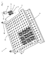
- FIG. 1 a first embodiment of a receiving body 2 is shown in a holding device 1.
- the holding device 1 consists of at least two stackable support platforms 4, which are supported by means of four spacers 32 which are arranged in the corner regions of the support plate 4 and fixed there, to each other.
- a plurality of receiving openings 31 are incorporated, in each of which a receiving body 2 is einklippsbar or inserted.
- the receiving body 2 is to be attached to the support plate 4 in a position-oriented manner and by this means isolated objects 5, for example screws, Nuts, tools or the like kept and stored for transport and processing purposes.
- the respective receiving body 2, and this is particularly in the FIGS. 2a and 2 B can be seen, consists essentially of a bottom 7, are attached to the four perpendicularly projecting from this holding finger 9.
- the retaining fingers 9 and the bottom 7 include an externally accessible space 13, in which the respective objects 5 can be inserted.
- one or more circumferential support ribs 14 may be provided, so that the retaining fingers 9 are mutually supported against each other and therefore can not bend inward or outward.
- each two webs 11 of two adjacent receiving body 2 are thus directed towards each other and form a receiving space 12 through which the article 5 is held stored such that the article 5 is accessible only from an opposite end of the bottom 7 through an insertion 17.
- the webs 11 of the receiving body 2 are L-shaped or T-shaped in cross section in the longitudinal direction 8, so that a plurality of projecting from the lateral surface 10 of the receiving body 2 paragraphs 15 are formed.
- the shoulder 15 is aligned in a plane parallel to and spaced from the bottom 7 and forms, together with the paragraphs 15 of the adjacent receiving body 2, a horizontal bearing for the article 5 in the receiving space 12, the four directed to the center of the receiving body 2 webs 11 and the heels 15 of which form a horizontal support for the object 5 in the space 13.
- the shoulders 15 may lie in a common plane with the floor 7 or in a plane parallel and spaced from the floor 7.
- the receiving body 2 and its retaining fingers 9 and the webs 11 are dimensioned such that the space formed by the one or more retaining fingers 9 13 is geometrically identical to the receiving space 12 formed.
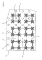
- FIG. 3 a second embodiment of a receiving body 2 is shown in a holding device 1.
- a plurality of receiving openings 31 is incorporated, in each of which a receiving body 2 is einklippsbar.
- two opposing slots 33 are provided in each case, which cooperate with the receiving body 2 and act as an anti-rotation.
- From the bottom 7 of the receiving body 2 are perpendicular to and parallel to the longitudinal axis 8 from holding fingers 9, which are connected by annular support ribs 14 together and together with the holding fingers 9 form an insertion 17.
- the holding fingers 9 and the bottom 7 enclose the space 13, which is accessible only from an end face opposite the bottom 7, the insertion opening 17 for positioning the object 5.
- On the outside of the lateral surface 10 four webs 11 are integrally formed over the circumference in a uniform angular pitch.
- the webs 11 of four adjacent receiving bodies 2 form a receiving space 12, which is formed around the center 21 of the four receiving body 2.
- the webs 11 of the four arranged in a square receiving body 2 are aligned with each other and have in the longitudinal axis 8 on an L-shaped or T-shaped cross-sectional shape. As a result, a shoulder 15 is formed, is held by an object 5 spaced from the support plate 4.
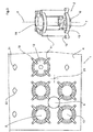
- FIG. 3a From the FIG. 3a is a development of the receiving body 2 according to FIG. 3 refer to.
- Four retaining fingers 9 are perpendicular from the bottom 7 aligned to the longitudinal axis 8 and form together with the bottom 7 a space 13.
- the support ribs 14 together with the holding fingers 9 an insertion opening 17 through which the object 5 can be inserted into the space 13.
- On the lateral surface 10 a plurality of outwardly projecting into the space 13 paragraphs 15 are formed, which are arranged in a plane parallel and spaced from the plane of the bottom 7.
- receiving bodies 2 arranged adjacently in a plane on the carrier plate 4 form a receiving space 12 whose center 21 corresponds to the geometric center of the four receiving bodies 2.
- the object 5 inserted into the receiving space 12 is held horizontally by the holding fingers 9 and the supporting ribs 14, respectively, and horizontally supported by the shoulders 15 facing each other.
- the receiving space 12 is geometrically identical to the space 13 formed by the holding fingers 9.
- FIG. 4 Shown is a receiving body composite 3, which is made in one piece from four receiving bodies 2 in an injection molding process.
- the respective receiving body composite 3 consists essentially of four interconnected receiving bodies 2, at the bottom 7, and in contrast to the region from which the retaining fingers 9 protrude, a base 16 is formed, through which the receiving body composite 3 on the support plate 4 and in Interaction with the receiving openings 31 can be fixed.
- projecting webs 11 are respectively formed on the lateral surface 10 of the receiving body 2 from the lateral surface. In the longitudinal direction 8, the webs 11 in cross-section L- or T-shaped, so that paragraphs 15 are formed.
- a receiving space 13 is formed, through which the article 5 is held stored such that this exclusively from the bottom 7 opposite end face is accessible through an insertion opening 17.
- the receiving body composite 3 may be integrally formed with the support plate 4 as a molded part. Also, a receiving body composite 3 may be formed from a plurality of receiving bodies 2, which are positively or non-positively connected by a connecting element 19. Such a development of the receiving body composite is the FIG. 4a refer to.
- the connecting elements 19 are arranged on the shoulders 15 such that a plurality of receiving bodies 2 or isolatedachi redesignunde 3 form a composite receiving body composite 3.
- Such a receiving body composite 3 may have one or more pedestals 16, by which the receiving body composite 3 is fixed to the support plate 4.
- the receiving body composite 3 may be formed from a composite of at least two receiving bodies 2 arranged in pairs. A receiving body composite 3 with four or more receiving bodies 2 has proved to be advantageous.
- FIG. 5 the arrangement of the receiving body composite 3 can be seen.
- the arranged on the support plate 4 receiving body composites 3 are aligned with each other so that the webs 11 of the respective receiving body 2 of the receiving body composite 3 and theracanalysisverbunde 3 form one or more receiving spaces 12.
- the geometric dimensions of the spaces 13 formed by the holding fingers 9 of the receiving body 2 are identical to the geometric dimensions of the receiving spaces 12 formed.
- FIGS. 6a and 6b Different bases are to be taken as locking devices or torsion-fuses, which cooperate with the receiving openings 31 of the support plate 4.
- the FIG. 6a are three receiving body 2 can be seen, each having different types of base 16.
- the base 16 may be formed as a thread 25, as a clip connection 26 or as Einrastfuß 27, through which the receiving body is attached to the support plate.
- the receiving openings 31 of the support plate 4 are arranged adjacent to each other in the embodiments such that four receiving openings 31 form a square.
- the receiving body 2 and the receiving body composite 3 can therefore be arranged adjacent to each other in pairs or in a square arrangement. Further geometric patterns, in particular an isosceles triangle, a rectangle or the like, for the arrangement of the receiving openings 31 or the receiving body 2 or the receiving body composite 3 to form further receiving spaces 12 are possible.
- the respectively formed receiving spaces 12 may also have different geometric dimensions than the spaces 13. This is particularly advantageous if articles 5 with different geometric dimensions in the respective receiving spaces 12 and spaces 13 should be used.
- the paragraphs 15 of the webs 11 may be arranged in different spaced planes parallel to the bottom 7 in order to vary the height of the spaces 13 and the receiving spaces 12.
- the paragraphs 15, which protrude from the lateral surface 10 of the receiving body 12 and the receiving body composite 3, can also be designed as around the receiving body 2 and the receiving body composite 3 circumferential annular shoulder 15.
- the heel 15 thus formed may be disposed in the plane of the floor 7 or be parallel to and spaced from the floor 7 in a plane. A position-oriented fixation on the support plate 4 is thus not required.
Landscapes
- Engineering & Computer Science (AREA)
- Mechanical Engineering (AREA)
- Packages (AREA)
- Snaps, Bayonet Connections, Set Pins, And Snap Rings (AREA)
- Injection Moulding Of Plastics Or The Like (AREA)
Priority Applications (1)
| Application Number | Priority Date | Filing Date | Title |
|---|---|---|---|
| EP15166236.8A EP2952440B1 (fr) | 2014-06-03 | 2015-05-04 | Corps de réception, dispositif de retenue comprenant des corps de réception et dispositif comprenant des assemblages de corps de réception |
Applications Claiming Priority (2)
| Application Number | Priority Date | Filing Date | Title |
|---|---|---|---|
| EP14170882.6A EP2952439B1 (fr) | 2014-06-03 | 2014-06-03 | Assemblage de supports de réception |
| EP15166236.8A EP2952440B1 (fr) | 2014-06-03 | 2015-05-04 | Corps de réception, dispositif de retenue comprenant des corps de réception et dispositif comprenant des assemblages de corps de réception |
Publications (2)
| Publication Number | Publication Date |
|---|---|
| EP2952440A1 true EP2952440A1 (fr) | 2015-12-09 |
| EP2952440B1 EP2952440B1 (fr) | 2017-07-19 |
Family
ID=50884717
Family Applications (2)
| Application Number | Title | Priority Date | Filing Date |
|---|---|---|---|
| EP14170882.6A Active EP2952439B1 (fr) | 2014-06-03 | 2014-06-03 | Assemblage de supports de réception |
| EP15166236.8A Active EP2952440B1 (fr) | 2014-06-03 | 2015-05-04 | Corps de réception, dispositif de retenue comprenant des corps de réception et dispositif comprenant des assemblages de corps de réception |
Family Applications Before (1)
| Application Number | Title | Priority Date | Filing Date |
|---|---|---|---|
| EP14170882.6A Active EP2952439B1 (fr) | 2014-06-03 | 2014-06-03 | Assemblage de supports de réception |
Country Status (1)
| Country | Link |
|---|---|
| EP (2) | EP2952439B1 (fr) |
Cited By (8)
| Publication number | Priority date | Publication date | Assignee | Title |
|---|---|---|---|---|
| CN109367968A (zh) * | 2018-12-05 | 2019-02-22 | 盐城远大金属科技有限公司 | 一种凸轮专用工装 |
| USD945735S1 (en) | 2019-05-15 | 2022-03-08 | Chep Technology Pty Limited | Part for a pallet |
| USD949509S1 (en) | 2019-05-15 | 2022-04-19 | Chep Technology Pty Limited | Part for a pallet |
| USD951580S1 (en) | 2019-05-15 | 2022-05-10 | Chep Technology Pty Limited | Part for a pallet |
| US11542062B2 (en) | 2017-11-16 | 2023-01-03 | Chep Technology Pty Limited | Pallet with support modules |
| WO2023104979A1 (fr) * | 2021-12-08 | 2023-06-15 | Zell Systemtechnik Gmbh | Support de pièce à travailler |
| CN118877495A (zh) * | 2024-10-07 | 2024-11-01 | 苏州赛腾精密电子股份有限公司 | 多承载座联动式夹紧定位接料单元 |
| EP4501805A3 (fr) * | 2023-08-03 | 2025-04-16 | Shuert Technologies, Llc | Structure d'expédition empilable en plastique moulé pour blocs-batteries ev |
Families Citing this family (3)
| Publication number | Priority date | Publication date | Assignee | Title |
|---|---|---|---|---|
| IT201700087388A1 (it) | 2017-07-28 | 2019-01-28 | Ferremi Luca S R L A Socio Unico | Sistema portapezzi per uso industriale |
| WO2019216827A1 (fr) * | 2018-05-08 | 2019-11-14 | Lam Choon Sen David | Séparateur et plaque de séparation |
| DE102019135183A1 (de) * | 2019-12-19 | 2021-06-24 | Oerlikon Surface Solutions Ag, Pfäffikon | Haltesystem zum Halten von Substraten |
Citations (7)
| Publication number | Priority date | Publication date | Assignee | Title |
|---|---|---|---|---|
| FR1365477A (fr) * | 1963-05-22 | 1964-07-03 | Vitherm | Casier à bouteilles perfectionné |
| US5660279A (en) * | 1992-07-29 | 1997-08-26 | Rehrig Pacific Company, Inc. | Stackable low depth bottle case |
| DE202012103711U1 (de) * | 2012-09-27 | 2012-11-15 | Ingo Zell | Trägerplatte eines Werkstückträgersystems sowie Werkstückträgersystem |
| EP2570234A1 (fr) * | 2011-09-13 | 2013-03-20 | Alwa GmbH Konstruktion & Formenbau | Support de réception |
| EP2687454A1 (fr) * | 2012-07-17 | 2014-01-22 | ALWA GmbH & Co. KG Konstruktion & Formenbau | Dispositif d'empilage d'au moins deux plaques de support |
| DE102012020591A1 (de) * | 2012-10-22 | 2014-04-24 | Fischer-Draht Gmbh | Werkstückträger zur Lagerung von Werkstücken |
| EP2810887A1 (fr) * | 2013-06-05 | 2014-12-10 | ALWA GmbH & Co. KG Konstruktion & Formenbau | Dispositif de logement et de support d'objets ainsi que dispositif de transport |
-
2014
- 2014-06-03 EP EP14170882.6A patent/EP2952439B1/fr active Active
-
2015
- 2015-05-04 EP EP15166236.8A patent/EP2952440B1/fr active Active
Patent Citations (8)
| Publication number | Priority date | Publication date | Assignee | Title |
|---|---|---|---|---|
| FR1365477A (fr) * | 1963-05-22 | 1964-07-03 | Vitherm | Casier à bouteilles perfectionné |
| US5660279A (en) * | 1992-07-29 | 1997-08-26 | Rehrig Pacific Company, Inc. | Stackable low depth bottle case |
| EP2570234A1 (fr) * | 2011-09-13 | 2013-03-20 | Alwa GmbH Konstruktion & Formenbau | Support de réception |
| EP2570234B1 (fr) | 2011-09-13 | 2013-11-20 | ALWA GmbH & Co. KG Konstruktion & Formenbau | Support de réception |
| EP2687454A1 (fr) * | 2012-07-17 | 2014-01-22 | ALWA GmbH & Co. KG Konstruktion & Formenbau | Dispositif d'empilage d'au moins deux plaques de support |
| DE202012103711U1 (de) * | 2012-09-27 | 2012-11-15 | Ingo Zell | Trägerplatte eines Werkstückträgersystems sowie Werkstückträgersystem |
| DE102012020591A1 (de) * | 2012-10-22 | 2014-04-24 | Fischer-Draht Gmbh | Werkstückträger zur Lagerung von Werkstücken |
| EP2810887A1 (fr) * | 2013-06-05 | 2014-12-10 | ALWA GmbH & Co. KG Konstruktion & Formenbau | Dispositif de logement et de support d'objets ainsi que dispositif de transport |
Cited By (9)
| Publication number | Priority date | Publication date | Assignee | Title |
|---|---|---|---|---|
| US11542062B2 (en) | 2017-11-16 | 2023-01-03 | Chep Technology Pty Limited | Pallet with support modules |
| US11912462B2 (en) | 2017-11-16 | 2024-02-27 | Chep Technology Pty Limited | Support module |
| CN109367968A (zh) * | 2018-12-05 | 2019-02-22 | 盐城远大金属科技有限公司 | 一种凸轮专用工装 |
| USD945735S1 (en) | 2019-05-15 | 2022-03-08 | Chep Technology Pty Limited | Part for a pallet |
| USD949509S1 (en) | 2019-05-15 | 2022-04-19 | Chep Technology Pty Limited | Part for a pallet |
| USD951580S1 (en) | 2019-05-15 | 2022-05-10 | Chep Technology Pty Limited | Part for a pallet |
| WO2023104979A1 (fr) * | 2021-12-08 | 2023-06-15 | Zell Systemtechnik Gmbh | Support de pièce à travailler |
| EP4501805A3 (fr) * | 2023-08-03 | 2025-04-16 | Shuert Technologies, Llc | Structure d'expédition empilable en plastique moulé pour blocs-batteries ev |
| CN118877495A (zh) * | 2024-10-07 | 2024-11-01 | 苏州赛腾精密电子股份有限公司 | 多承载座联动式夹紧定位接料单元 |
Also Published As
| Publication number | Publication date |
|---|---|
| EP2952439B1 (fr) | 2016-08-24 |
| EP2952439A1 (fr) | 2015-12-09 |
| EP2952440B1 (fr) | 2017-07-19 |
Similar Documents
| Publication | Publication Date | Title |
|---|---|---|
| EP2952440B1 (fr) | Corps de réception, dispositif de retenue comprenant des corps de réception et dispositif comprenant des assemblages de corps de réception | |
| DE112012007163T5 (de) | Palette | |
| EP2860126B1 (fr) | Dispositif de support d'objets et corps de liaison correspondant | |
| EP3480128B1 (fr) | Dispositif de réception et de blocage d'objets et cadre porteur correspondant | |
| EP2965998B1 (fr) | Plaque de support | |
| EP2546528A1 (fr) | Platine murale pour ventilateur axial | |
| EP2570234B1 (fr) | Support de réception | |
| EP2860127B1 (fr) | Dispositif de support d'objets et corps de liaison correspondant | |
| EP3330196B1 (fr) | Dispositif destiné a la réception d'objets et connecteur correspondant | |
| DE19521575C2 (de) | Wafer-Korb in einem Wafer-Haltekasten | |
| EP2810887A1 (fr) | Dispositif de logement et de support d'objets ainsi que dispositif de transport | |
| EP2687454A1 (fr) | Dispositif d'empilage d'au moins deux plaques de support | |
| DE102007014850B4 (de) | Fertigungsstraße | |
| DE202014102215U1 (de) | Modularer Werkstückträger | |
| DE102012218637A1 (de) | Transportverpackung für ein ringförmiges Lagerteil | |
| EP0517281B1 (fr) | Manchon de fixation à monter sur un boulon fileté | |
| DE202019102947U1 (de) | Behälterteller zum Aufnehmen und stehenden Transport eines Behälters | |
| EP1760680B1 (fr) | Panneau pour l'identification | |
| DE10055323C1 (de) | Dreidimensionale Struktur aus Gitterplatten | |
| EP2486827A1 (fr) | Elément de ressort | |
| WO2023104981A1 (fr) | Plaque support | |
| DE102016115771B3 (de) | Vorrichtung zum Transport von Innenausstattungsteilen | |
| DE102024104398A1 (de) | Magnet-Schleiflehre mit mehrteiligem, hohlem Körper | |
| DE202023101952U1 (de) | Traggestell | |
| DE102013226353A1 (de) | Werkzeugwagen |
Legal Events
| Date | Code | Title | Description |
|---|---|---|---|
| PUAI | Public reference made under article 153(3) epc to a published international application that has entered the european phase |
Free format text: ORIGINAL CODE: 0009012 |
|
| AK | Designated contracting states |
Kind code of ref document: A1 Designated state(s): AL AT BE BG CH CY CZ DE DK EE ES FI FR GB GR HR HU IE IS IT LI LT LU LV MC MK MT NL NO PL PT RO RS SE SI SK SM TR |
|
| AX | Request for extension of the european patent |
Extension state: BA ME |
|
| RIN1 | Information on inventor provided before grant (corrected) |
Inventor name: WASMEIER, ALBERT |
|
| 17P | Request for examination filed |
Effective date: 20160502 |
|
| RBV | Designated contracting states (corrected) |
Designated state(s): AL AT BE BG CH CY CZ DE DK EE ES FI FR GB GR HR HU IE IS IT LI LT LU LV MC MK MT NL NO PL PT RO RS SE SI SK SM TR |
|
| 17Q | First examination report despatched |
Effective date: 20160922 |
|
| GRAP | Despatch of communication of intention to grant a patent |
Free format text: ORIGINAL CODE: EPIDOSNIGR1 |
|
| RIC1 | Information provided on ipc code assigned before grant |
Ipc: B23Q 7/14 20060101ALN20170126BHEP Ipc: B65D 19/44 20060101AFI20170126BHEP Ipc: B65D 19/38 20060101ALN20170126BHEP |
|
| RIC1 | Information provided on ipc code assigned before grant |
Ipc: B65D 19/38 20060101ALN20170202BHEP Ipc: B65D 19/44 20060101AFI20170202BHEP Ipc: B23Q 7/14 20060101ALN20170202BHEP |
|
| INTG | Intention to grant announced |
Effective date: 20170217 |
|
| GRAS | Grant fee paid |
Free format text: ORIGINAL CODE: EPIDOSNIGR3 |
|
| GRAA | (expected) grant |
Free format text: ORIGINAL CODE: 0009210 |
|
| AK | Designated contracting states |
Kind code of ref document: B1 Designated state(s): AL AT BE BG CH CY CZ DE DK EE ES FI FR GB GR HR HU IE IS IT LI LT LU LV MC MK MT NL NO PL PT RO RS SE SI SK SM TR |
|
| REG | Reference to a national code |
Ref country code: GB Ref legal event code: FG4D Free format text: NOT ENGLISH |
|
| REG | Reference to a national code |
Ref country code: CH Ref legal event code: EP |
|
| REG | Reference to a national code |
Ref country code: IE Ref legal event code: FG4D Free format text: LANGUAGE OF EP DOCUMENT: GERMAN |
|
| REG | Reference to a national code |
Ref country code: AT Ref legal event code: REF Ref document number: 910144 Country of ref document: AT Kind code of ref document: T Effective date: 20170815 |
|
| REG | Reference to a national code |
Ref country code: DE Ref legal event code: R096 Ref document number: 502015001457 Country of ref document: DE |
|
| REG | Reference to a national code |
Ref country code: NL Ref legal event code: MP Effective date: 20170719 |
|
| REG | Reference to a national code |
Ref country code: LT Ref legal event code: MG4D |
|
| PG25 | Lapsed in a contracting state [announced via postgrant information from national office to epo] |
Ref country code: NL Free format text: LAPSE BECAUSE OF FAILURE TO SUBMIT A TRANSLATION OF THE DESCRIPTION OR TO PAY THE FEE WITHIN THE PRESCRIBED TIME-LIMIT Effective date: 20170719 Ref country code: HR Free format text: LAPSE BECAUSE OF FAILURE TO SUBMIT A TRANSLATION OF THE DESCRIPTION OR TO PAY THE FEE WITHIN THE PRESCRIBED TIME-LIMIT Effective date: 20170719 Ref country code: SE Free format text: LAPSE BECAUSE OF FAILURE TO SUBMIT A TRANSLATION OF THE DESCRIPTION OR TO PAY THE FEE WITHIN THE PRESCRIBED TIME-LIMIT Effective date: 20170719 Ref country code: LT Free format text: LAPSE BECAUSE OF FAILURE TO SUBMIT A TRANSLATION OF THE DESCRIPTION OR TO PAY THE FEE WITHIN THE PRESCRIBED TIME-LIMIT Effective date: 20170719 Ref country code: NO Free format text: LAPSE BECAUSE OF FAILURE TO SUBMIT A TRANSLATION OF THE DESCRIPTION OR TO PAY THE FEE WITHIN THE PRESCRIBED TIME-LIMIT Effective date: 20171019 Ref country code: FI Free format text: LAPSE BECAUSE OF FAILURE TO SUBMIT A TRANSLATION OF THE DESCRIPTION OR TO PAY THE FEE WITHIN THE PRESCRIBED TIME-LIMIT Effective date: 20170719 |
|
| PG25 | Lapsed in a contracting state [announced via postgrant information from national office to epo] |
Ref country code: RS Free format text: LAPSE BECAUSE OF FAILURE TO SUBMIT A TRANSLATION OF THE DESCRIPTION OR TO PAY THE FEE WITHIN THE PRESCRIBED TIME-LIMIT Effective date: 20170719 Ref country code: BG Free format text: LAPSE BECAUSE OF FAILURE TO SUBMIT A TRANSLATION OF THE DESCRIPTION OR TO PAY THE FEE WITHIN THE PRESCRIBED TIME-LIMIT Effective date: 20171019 Ref country code: LV Free format text: LAPSE BECAUSE OF FAILURE TO SUBMIT A TRANSLATION OF THE DESCRIPTION OR TO PAY THE FEE WITHIN THE PRESCRIBED TIME-LIMIT Effective date: 20170719 Ref country code: ES Free format text: LAPSE BECAUSE OF FAILURE TO SUBMIT A TRANSLATION OF THE DESCRIPTION OR TO PAY THE FEE WITHIN THE PRESCRIBED TIME-LIMIT Effective date: 20170719 Ref country code: IS Free format text: LAPSE BECAUSE OF FAILURE TO SUBMIT A TRANSLATION OF THE DESCRIPTION OR TO PAY THE FEE WITHIN THE PRESCRIBED TIME-LIMIT Effective date: 20171119 Ref country code: GR Free format text: LAPSE BECAUSE OF FAILURE TO SUBMIT A TRANSLATION OF THE DESCRIPTION OR TO PAY THE FEE WITHIN THE PRESCRIBED TIME-LIMIT Effective date: 20171020 Ref country code: PL Free format text: LAPSE BECAUSE OF FAILURE TO SUBMIT A TRANSLATION OF THE DESCRIPTION OR TO PAY THE FEE WITHIN THE PRESCRIBED TIME-LIMIT Effective date: 20170719 |
|
| REG | Reference to a national code |
Ref country code: DE Ref legal event code: R097 Ref document number: 502015001457 Country of ref document: DE |
|
| PG25 | Lapsed in a contracting state [announced via postgrant information from national office to epo] |
Ref country code: DK Free format text: LAPSE BECAUSE OF FAILURE TO SUBMIT A TRANSLATION OF THE DESCRIPTION OR TO PAY THE FEE WITHIN THE PRESCRIBED TIME-LIMIT Effective date: 20170719 Ref country code: RO Free format text: LAPSE BECAUSE OF FAILURE TO SUBMIT A TRANSLATION OF THE DESCRIPTION OR TO PAY THE FEE WITHIN THE PRESCRIBED TIME-LIMIT Effective date: 20170719 Ref country code: CZ Free format text: LAPSE BECAUSE OF FAILURE TO SUBMIT A TRANSLATION OF THE DESCRIPTION OR TO PAY THE FEE WITHIN THE PRESCRIBED TIME-LIMIT Effective date: 20170719 |
|
| REG | Reference to a national code |
Ref country code: FR Ref legal event code: PLFP Year of fee payment: 4 |
|
| PLBE | No opposition filed within time limit |
Free format text: ORIGINAL CODE: 0009261 |
|
| STAA | Information on the status of an ep patent application or granted ep patent |
Free format text: STATUS: NO OPPOSITION FILED WITHIN TIME LIMIT |
|
| PG25 | Lapsed in a contracting state [announced via postgrant information from national office to epo] |
Ref country code: EE Free format text: LAPSE BECAUSE OF FAILURE TO SUBMIT A TRANSLATION OF THE DESCRIPTION OR TO PAY THE FEE WITHIN THE PRESCRIBED TIME-LIMIT Effective date: 20170719 Ref country code: SM Free format text: LAPSE BECAUSE OF FAILURE TO SUBMIT A TRANSLATION OF THE DESCRIPTION OR TO PAY THE FEE WITHIN THE PRESCRIBED TIME-LIMIT Effective date: 20170719 Ref country code: SK Free format text: LAPSE BECAUSE OF FAILURE TO SUBMIT A TRANSLATION OF THE DESCRIPTION OR TO PAY THE FEE WITHIN THE PRESCRIBED TIME-LIMIT Effective date: 20170719 |
|
| 26N | No opposition filed |
Effective date: 20180420 |
|
| PG25 | Lapsed in a contracting state [announced via postgrant information from national office to epo] |
Ref country code: SI Free format text: LAPSE BECAUSE OF FAILURE TO SUBMIT A TRANSLATION OF THE DESCRIPTION OR TO PAY THE FEE WITHIN THE PRESCRIBED TIME-LIMIT Effective date: 20170719 |
|
| PG25 | Lapsed in a contracting state [announced via postgrant information from national office to epo] |
Ref country code: MT Free format text: LAPSE BECAUSE OF FAILURE TO SUBMIT A TRANSLATION OF THE DESCRIPTION OR TO PAY THE FEE WITHIN THE PRESCRIBED TIME-LIMIT Effective date: 20170719 |
|
| REG | Reference to a national code |
Ref country code: CH Ref legal event code: PL |
|
| REG | Reference to a national code |
Ref country code: BE Ref legal event code: MM Effective date: 20180531 |
|
| PG25 | Lapsed in a contracting state [announced via postgrant information from national office to epo] |
Ref country code: MC Free format text: LAPSE BECAUSE OF FAILURE TO SUBMIT A TRANSLATION OF THE DESCRIPTION OR TO PAY THE FEE WITHIN THE PRESCRIBED TIME-LIMIT Effective date: 20170719 |
|
| REG | Reference to a national code |
Ref country code: IE Ref legal event code: MM4A |
|
| PG25 | Lapsed in a contracting state [announced via postgrant information from national office to epo] |
Ref country code: LI Free format text: LAPSE BECAUSE OF NON-PAYMENT OF DUE FEES Effective date: 20180531 Ref country code: CH Free format text: LAPSE BECAUSE OF NON-PAYMENT OF DUE FEES Effective date: 20180531 |
|
| PG25 | Lapsed in a contracting state [announced via postgrant information from national office to epo] |
Ref country code: LU Free format text: LAPSE BECAUSE OF NON-PAYMENT OF DUE FEES Effective date: 20180504 |
|
| PG25 | Lapsed in a contracting state [announced via postgrant information from national office to epo] |
Ref country code: IE Free format text: LAPSE BECAUSE OF NON-PAYMENT OF DUE FEES Effective date: 20180504 |
|
| PG25 | Lapsed in a contracting state [announced via postgrant information from national office to epo] |
Ref country code: BE Free format text: LAPSE BECAUSE OF NON-PAYMENT OF DUE FEES Effective date: 20180531 |
|
| PGFP | Annual fee paid to national office [announced via postgrant information from national office to epo] |
Ref country code: FR Payment date: 20190521 Year of fee payment: 5 |
|
| GBPC | Gb: european patent ceased through non-payment of renewal fee |
Effective date: 20190504 |
|
| PG25 | Lapsed in a contracting state [announced via postgrant information from national office to epo] |
Ref country code: TR Free format text: LAPSE BECAUSE OF FAILURE TO SUBMIT A TRANSLATION OF THE DESCRIPTION OR TO PAY THE FEE WITHIN THE PRESCRIBED TIME-LIMIT Effective date: 20170719 |
|
| PG25 | Lapsed in a contracting state [announced via postgrant information from national office to epo] |
Ref country code: GB Free format text: LAPSE BECAUSE OF NON-PAYMENT OF DUE FEES Effective date: 20190504 |
|
| PG25 | Lapsed in a contracting state [announced via postgrant information from national office to epo] |
Ref country code: PT Free format text: LAPSE BECAUSE OF FAILURE TO SUBMIT A TRANSLATION OF THE DESCRIPTION OR TO PAY THE FEE WITHIN THE PRESCRIBED TIME-LIMIT Effective date: 20170719 |
|
| PG25 | Lapsed in a contracting state [announced via postgrant information from national office to epo] |
Ref country code: MK Free format text: LAPSE BECAUSE OF NON-PAYMENT OF DUE FEES Effective date: 20170719 Ref country code: CY Free format text: LAPSE BECAUSE OF FAILURE TO SUBMIT A TRANSLATION OF THE DESCRIPTION OR TO PAY THE FEE WITHIN THE PRESCRIBED TIME-LIMIT Effective date: 20170719 Ref country code: HU Free format text: LAPSE BECAUSE OF FAILURE TO SUBMIT A TRANSLATION OF THE DESCRIPTION OR TO PAY THE FEE WITHIN THE PRESCRIBED TIME-LIMIT; INVALID AB INITIO Effective date: 20150504 |
|
| PG25 | Lapsed in a contracting state [announced via postgrant information from national office to epo] |
Ref country code: AL Free format text: LAPSE BECAUSE OF FAILURE TO SUBMIT A TRANSLATION OF THE DESCRIPTION OR TO PAY THE FEE WITHIN THE PRESCRIBED TIME-LIMIT Effective date: 20170719 |
|
| PG25 | Lapsed in a contracting state [announced via postgrant information from national office to epo] |
Ref country code: FR Free format text: LAPSE BECAUSE OF NON-PAYMENT OF DUE FEES Effective date: 20200531 |
|
| REG | Reference to a national code |
Ref country code: AT Ref legal event code: MM01 Ref document number: 910144 Country of ref document: AT Kind code of ref document: T Effective date: 20200504 |
|
| PG25 | Lapsed in a contracting state [announced via postgrant information from national office to epo] |
Ref country code: AT Free format text: LAPSE BECAUSE OF NON-PAYMENT OF DUE FEES Effective date: 20200504 |
|
| REG | Reference to a national code |
Ref country code: DE Ref legal event code: R082 Ref document number: 502015001457 Country of ref document: DE Representative=s name: GEITZ PATENTANWAELTE PARTG MBB, DE Ref country code: DE Ref legal event code: R082 Ref document number: 502015001457 Country of ref document: DE Representative=s name: GEITZ TRUCKENMUELLER LUCHT CHRIST PATENTANWAEL, DE |
|
| P01 | Opt-out of the competence of the unified patent court (upc) registered |
Effective date: 20230512 |
|
| PGFP | Annual fee paid to national office [announced via postgrant information from national office to epo] |
Ref country code: DE Payment date: 20250519 Year of fee payment: 11 |
|
| PGFP | Annual fee paid to national office [announced via postgrant information from national office to epo] |
Ref country code: IT Payment date: 20250530 Year of fee payment: 11 |