EP2952465B1 - Stufenloser getriebe des handlaufs - Google Patents
Stufenloser getriebe des handlaufs Download PDFInfo
- Publication number
- EP2952465B1 EP2952465B1 EP15170123.2A EP15170123A EP2952465B1 EP 2952465 B1 EP2952465 B1 EP 2952465B1 EP 15170123 A EP15170123 A EP 15170123A EP 2952465 B1 EP2952465 B1 EP 2952465B1
- Authority
- EP
- European Patent Office
- Prior art keywords
- handrail
- drive
- belt
- coupling device
- coupling
- Prior art date
- Legal status (The legal status is an assumption and is not a legal conclusion. Google has not performed a legal analysis and makes no representation as to the accuracy of the status listed.)
- Active
Links
Images



Classifications
-
- B—PERFORMING OPERATIONS; TRANSPORTING
- B66—HOISTING; LIFTING; HAULING
- B66B—ELEVATORS; ESCALATORS OR MOVING WALKWAYS
- B66B23/00—Component parts of escalators or moving walkways
- B66B23/02—Driving gear
- B66B23/04—Driving gear for handrails
-
- B—PERFORMING OPERATIONS; TRANSPORTING
- B66—HOISTING; LIFTING; HAULING
- B66B—ELEVATORS; ESCALATORS OR MOVING WALKWAYS
- B66B23/00—Component parts of escalators or moving walkways
- B66B23/02—Driving gear
- B66B23/04—Driving gear for handrails
- B66B23/06—Driving gear for handrails with means synchronising the operation of the steps or the carrying belts and the handrails
Definitions
- the present invention relates to a passenger transport device according to the preamble of patent claim 1.
- Conveying devices for transporting people, in particular escalators, moving walks or conveyor belts, in various designs are known from the prior art.
- Such devices are used for example for transporting people between levels of a building (escalators) or along a level path (moving walks).
- an escalator includes a plurality of steps or a belt on which people to be conveyed are to be carried from one location to another.
- a handrail is usually provided, which runs over a balustrade and provides a surface on which carried people can hold for example.
- Such a handrail typically has two handrail bands each having a flat surface which is aligned parallel to the floor or to the direction of movement of the conveyor.
- a segmented belt or pallet belt is conventionally driven by means of a drive.
- the handrail must in this case be driven in such a way that it moves uniformly with the pallet band.
- the drive of the pallet belt via appropriate transmission, such as chain drive also drives the handrail.
- the movement of the handrail is rigidly coupled to the movement of the pallet belt.
- this rigid coupling of the handrail or the handrail with the pallet band is associated with a number of disadvantages in terms of energy consumption and wear.
- the energy consumption of a typical escalator with no load about 400 W, of which about 80% fall on the drive of the handrail. Only the remaining 20% fall on the drive of the pallet belt.
- the life of a handrail is substantially determined by the number of its turns, and thus can be increased if the number of turns can be reduced.
- the aim is to provide a passenger transportation device which can be operated in an energy-efficient and user-friendly manner at the same time.
- the present invention proposes a passenger transport device with the features of claim 1.
- the drive of a segmented belt or pallet belt can be coupled in a simple manner with a mechanism for moving the handrail, or decoupled from this. It is according to the invention only a single drive for driving the segmented belt and the pallet belt needed. According to the invention, the operation of a passenger transport device is possible in a particularly energy-saving manner, since the handrail is not necessarily moved during a movement of the segmented belt. At the same time, a passenger approaching the passenger transport device can easily be signaled by the movement of the segmented belt that the passenger transport device is in operation. Conveniently, the handrail is coupled with the belt drive of the segmented belt only when an actual need exists, so for example, a passenger enters the passenger transport device.
- the coupling device comprises a continuously variable transmission for stepless adjustment of the speed of the handrail relative to the speed of the segmented belt.
- control the coupling device by means of a control device, in particular as a function of a detected presence of at least one passenger in the surroundings or on the passenger transport device.
- a suitable sensor system for example a light barrier, can be provided, by means of which a signal can be given to a control device, which is expedient for its coupling of the handrail to the segmented band.
- the coupling device is designed as an electromagnetic, hydraulic, pneumatic or mechanical coupling. Such couplings require little space, work very quietly and prove to be robust and reliable in practice.
- magnetorheological or electrorheological couplings can be precisely and quickly controlled by appropriate application of a suitable magnetic or electric field in a simple manner, working very quietly.
- a magnetorheological or electrorheological fluid used in this case alters its consistency, for example from liquid to gel, to solid under the influence of the magnetic field or the electric field.
- These liquids can be sealed in a very good way to the outside, wherein they have a low internal friction in the separated state. Further, they have a better heat dissipation, whereby operation in a slip state over long periods can be easily maintained.
- the formation of the coupling device as a multi-plate clutch.
- two handrail bands of a handrail can be coupled independently of one another by the segmented band.
- This measure can be achieved, for example, that only a handrail, conveniently the handrail on which a user or passenger is supported, is moved with the segmented band.
- the second handrail can in this case remain in its decoupled with respect to the segmented band state and thus stand still.
- the energy consumption of a Wegbelieseinreichtung invention is further optimized.
- the passenger transport device is designed as an escalator, moving walk or as a conveyor belt.
- FIG. 1 shows the drive of a trained example as an escalator passenger transport device according to the prior art in a schematic representation.
- the escalator has a drive unit 102, a main drive chain 104, a main drive sprocket 106, two drive wheels 108 (left) and 108 '(right) for a segmented belt, in the case of an escalator so a step belt (not shown), a main drive shaft 110, a drive pinion 112 for a handrail having two handrail bands (not shown), a handrail drive chain 114, a sprocket 116, a handrail drive shaft 118, and a handrail 120, 120 'for the handrail bands of the handrail, respectively.
- the drive unit 102 drives the main drive chain, which drives the two drive wheels 108, 108 'connected to the main drive shaft 110 for the step belt.
- the step belt is driven by and supported by the drive wheels 108, 108 '.
- the main drive shaft 110 also drives the drive pinion 112.
- the rotation of the drive pinion 112 is transmitted via the drive chain 114 and the sprocket 116, to the drive shaft 118 of the handrail.
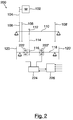
- FIG. 2 is a first preferred embodiment of the invention (for example, also designed as an escalator) passenger transport device according to the invention shown in a corresponding representation purely schematically. Same or similar components, as in FIG. 1 have been described are provided with the same reference numerals.
- the escalator here designated 200, has two clutches 222, 222 'for the two handrail straps of the handrail, a handrail control unit 224 and a main control unit 226 for the escalator as a whole.
- the couplings 222, 222 ' are detachably formed. This makes it possible to jointly drive the step belt and the handrail by means of the drive unit 102 in a first, coupled operating state. In a second, decoupled operating state However, it is also possible to decouple the handrail from the step band, and so for example to let the handrail stand still while the step band is kept in motion. This is a particularly energy-efficient operation of escalators realized.
- the clutches 222, 222 ' are individually and independently controllable by the control unit 224.
- the speed of the handrail can be adjusted differently from the speed of the step belt.
- the main control unit 226 is adapted to control the movement of the escalator in response to a desired speed as well as, for example, a carried load, ie, in particular, the entirety of the passengers being carried.
- the handrail control unit 224 communicates with the main control unit via a suitable communication channel, and is particularly designed to control the clutches 222, 222 '.
- FIG. 3 is a further embodiment of the passenger transport device according to the invention (hereby designated by 300) shown in a corresponding representation. Again, components already described are provided with the same reference numerals.
- the embodiment according to FIG. 3 is different from the one of FIG. 2 in that the coupling elements of the coupling 316 can only be actuated together, a movement of the handrail bands 120, 120 'independently of one another is therefore not possible. This control is characterized by a particular simplicity, and is suitable for a variety of applications or situations.
- coupling device of a passenger transport device 400 is formed as a viscous coupling and 422, 422 'designated.
- a viscous coupling the rotational movement of the shaft 118 (input side) is transmitted to a first disc or lamella 423, which transmits it to a fluid provided between this disc and a further disc 424, which in turn the second disc 424 (output side) drives.
- the viscous coupling is designed as a magnetorheological or electrorheological coupling.
- FIG. 5 is shown as passenger transport means an escalator 500 schematically, in which the movement of the handrail is coupled via a continuously variable transmission or CVT gear 502 to the movement of the step band.
- the CVT transmission 502 Continuous Variable Transmission
- the CVT transmission 502 has on the drive side a wedge disk pair 518 and on the output side a wedge disk pair 520.
- Drive side and output side of the CVT 502 are interconnected via a V-belt 502.
- the distance between both wedge disk pairs 518, 520 is changeable.
- the distance of the output-side wedge disks 520 is regulated by a spring 522.
- the V-belt 502 is circular at both ends.
Landscapes
- Escalators And Moving Walkways (AREA)
Description
- Die vorliegende Erfindung betrifft eine Personenbeförderungseinrichtung nach dem Oberbegriff des Patentanspruchs 1.
- Aus dem Stand der Technik sind Fördereinrichtungen zum Befördern von Personen, insbesondere Fahrtreppen, Fahrsteige oder Förderbänder, in vielfältigen Ausführungen bekannt.
- Derartige Einrichtungen werden beispielsweise zum Befördern von Personen zwischen Ebenen eines Gebäudes (Fahrtreppen) oder entlang eines ebenen Weges (Fahrsteige) verwendet.
- Eine Fahrtreppe umfasst beispielsweise eine Mehrzahl von Stufen oder ein Band bzw. einen Gurt, auf dem zu fördernde Personen stehen, um von einer Stelle zu einer anderen befördert zu werden. Zusätzlich ist in der Regel ein Handlauf vorgesehen, der über eine Balustrade läuft und eine Oberfläche bereitstellt, an der sich beförderte Personen beispielsweise festhalten können.
- Ein derartiger Handlauf weist typischerweise zwei Handlaufbänder mit jeweils einer ebenen Oberfläche auf, die parallel zum Boden oder zu der Bewegungsrichtung der Beförderungseinrichtung ausgerichtet ist. Ein segmentiertes Band bzw. Palettenband wird herkömmlicherweise mittels eines Antriebs angetrieben. Der Handlauf muss hierbei derart angetrieben werden, dass er sich gleichförmig mit dem Palettenband bewegt. Herkömmlicherweise treibt der Antrieb des Palettenbandes über entsprechende Getriebe, beispielsweise Kettengetriebe, auch den Handlauf an.
- Hierbei ist die Bewegung des Handlaufs starr an die Bewegung des Palettenbandes gekoppelt.
- Diese starre Kopplung des Handlaufs bzw. der Handlaufbänder mit dem Palettenband ist jedoch mit einer Reihe von Nachteilen hinsichtlich des Energieverbrauchs und des Verschleißes verbunden. Beispielsweise beträgt der Energieverbrauch einer typischen Fahrtreppe ohne Last etwa 400 W, wovon ca. 80 % auf den Antrieb der Handlaufbänder fallen. Lediglich die verbleibenden 20 % fallen auf den Antrieb des Palettenbandes. Des Weiteren wird die Lebensdauer eines Handlaufbandes im Wesentlichen von der Anzahl seiner Umläufe bestimmt, und kann somit erhöht werden, wenn die Anzahl der Umläufe verringert werden kann.
- Es ist bekannt, Personenbeförderungseinrichtungen verlangsamt anzutreiben, wenn gerade kein Benutzer transportiert wird. Bei derartigen Langsamfahrten werden beispielsweise Geschwindigkeiten von 0,1 m/s eingestellt, wobei eine typische Normalfahrt mit Geschwindigkeiten von etwa 0,5 m/s arbeitet. Auch hier kommt es, wenn gleich im verminderten Umfang, zu den oben beschriebenen Problemen bezüglich Energieverbrauch und Lebensdauer des Handlaufbandes.
- Um Energie einzusparen, ist es auch bekannt, Personenbeförderungseinrichtungen lediglich dann anzutreiben, wenn die Einrichtung gerade von einem Benutzer verwendet wird. Typischerweise setzt sich die Einrichtung in Bewegung, kurz bevor eine Person sie betritt. Als nachteilig wird jedoch angesehen, dass es für eine Person, die sich der Einrichtung nähert, zunächst nicht möglich ist, zu erkennen, ob diese aktuell betriebsbereit ist oder nicht, wenn das Palettenband nicht in Bewegung ist. Hierdurch ist die Benutzerfreundlichkeit insgesamt beeinträchtigt.
- Aus der
DE 11 2006 004 175 T5 ist eine Vorrichtung zum Antrieb einer Personenfördereinrichtung bekannt, bei der Palettenband und Handlauf mit separaten Antrieben ausgebildet sind. Ein derartiger zusätzlicher Antrieb führt zu zusätzlichem Wartungsaufwand und erhöht die Komplexität des Gesamtsystems. - Aus der
JP 7-252072 - Ferner ist aus der
DE 195 39 796 A1 eine Sicherheitseinrichtung für Personenförderanlagen bekannt, wobei durch das Betätigen eines Sicherheitsschalters das Handlaufantriebsrad mittels eines Kupplungselementes vom Antrieb getrennt wird. - In der
US 7 954 620 B2 wird eine Fahrtreppe beschrieben, welche jeweils für das Stufenband und den Handlauf einen separaten Antrieb vorschlägt. - Vor diesem Hintergrund wird angestrebt, eine Personenbeförderungseinrichtung zur Verfügung zu stellen, welche energieeffizient und gleichzeitig bedienerfreundlich betrieben werden kann.
- Ausgehend von dem dargestellten Stand der Technik schlägt die vorliegende Erfindung eine Personenbeförderungseinrichtung mit den Merkmalen des Patentanspruchs 1 vor.
- Vorteilhafte Ausgestaltungen sind Gegenstand der Unteransprüche sowie der nachfolgenden Beschreibung.
- Erfindungsgemäß ist der Antrieb eines segmentierten Bandes bzw. Palettenbandes in einfacher Weise mit einem Mechanismus zum Bewegen des Handlaufs koppelbar, bzw. von diesem entkoppelbar. Es wird erfindungsgemäß lediglich ein einziger Antrieb zum Antreiben des segmentierten Bandes und des Palettenbandes benötigt. Erfindungsgemäß ist der Betrieb einer Personbeförderungseinrichtung in besonders energiesparender Weise möglich, da der Handlauf bei einer Bewegung des segmentierten Bandes nicht notwendigerweise mitbewegt wird. Gleichzeitig kann einem Passagier, der sich der Personbeförderungseinrichtung nähert, durch die Bewegung des segmentierten Bandes in einfacher Weise signalisiert werden, dass die Personbeförderungseinrichtung in Betrieb ist. Zweckmäßigerweise wird der Handlauf erst dann mit dem Bandantrieb des segmentierten Bandes gekoppelt, wenn ein tatsächlicher Bedarf besteht, also beispielsweise ein Passagier die Personbeförderungseinrichtung betritt.
- Zweckmäßigerweise weist die Kopplungseinrichtung ein stufenloses Getriebe zur stufenlosen Einstellung der Geschwindigkeit des Handlaufs relativ zur Geschwindigkeit des segmentierten Bandes auf.
- Besonders bevorzugt ist, mittels einer Steuereinrichtung die Kopplungseinrichtung insbesondere in Abhängigkeit von einer erfassten Anwesenheit wenigstens eines Passagiers in der Umgebung oder auf der Personenbeförderungseinrichtung zu steuern. Insbesondere kann eine geeignete Sensorik, beispielsweise eine Lichtschranke, vorgesehen sein, mittels der einer Steuerungseinrichtung ein Signal gegeben werden kann, das seine Kopplung des Handlaufs mit dem segmentierten Band zweckmäßig ist.
- Besonders bevorzugt ist, dass die Kopplungseinrichtung als elektromagnetische, hydraulische, pneumatische oder mechanische Kupplung ausgebildet ist. Derartige Kupplungen benötigen wenig Bauraum, arbeiten sehr leise und erweisen sich in der Praxis als robust und zuverlässig.
- Besonders bevorzugt ist der Einsatz von magnetorheologischen oder elektrorheologischen Kupplungen. Derartige Kupplungen sind durch entsprechendes Anlegen eines geeigneten magnetischen oder elektrischen Feldes in einfacher Weise präzise und schnell steuerbar, wobei sie besonders leise arbeiten. Eine hierbei eingesetzte magnetorheologische oder elektrorheologische Flüssigkeit verändert unter Einfluss des Magnetfeldes bzw. des elektrischen Feldes ihre Konsistenz beispielsweise von flüssig über gelförmig zu fest. Diese Flüssigkeiten lassen sich in sehr guter Weise nach außen abdichten, wobei sie im getrennten Zustand eine geringe innere Reibung aufweisen. Ferner weisen sie eine bessere Wärmeableitung auf, wodurch ein Betrieb in einem Schlupfzustand über längere Zeiten problemlos aufrechterhalten werden kann.
- Besonders bevorzugt ist auch die Ausbildung der Kopplungseinrichtung als Lamellenkupplung.
- Gemäß einer besonders bevorzugten Ausführungsform der erfindungsgemäßen Personenbeförderungseinrichtung sind zwei Handlaufbänder eines Handlaufs unabhängig von einander von dem segmentierten Band koppelbar. Mit dieser Maßnahme kann beispielsweise erreicht werden, dass lediglich ein Handlaufband, zweckmäßigerweise das Handlaufband, auf dem sich ein Benutzer bzw. Passagier abstützt, mit dem segmentierten Band bewegt wird. Das zweite Handlaufband kann hierbei in seinem bezüglich des segmentierten Bandes entkoppelten Zustand bleiben und somit stillstehen. Hiermit ist der Energieverbrauch einer erfindungsgemäßen Personenbeförderungseinreichtung weiter optimierbar.
- Zweckmäßigerweise ist die Personenbeförderungseinrichtung als Fahrtreppe, Fahrsteig oder als Förderband ausgebildet.
- Weitere Vorteile und Ausgestaltungen der Erfindung ergeben sich aus der Beschreibung und der beiliegenden Zeichnung.
- Es versteht sich, dass die vorstehend genannten und die nachstehend noch zu erläuternden Merkmale nicht nur in der jeweils angegebenen Kombination, sondern auch in anderen Kombinationen oder in Alleinstellung verwendbar sind, ohne den Rahmen der vorliegenden Erfindung zu verlassen.
- Die Erfindung ist anhand eines Ausführungsbeispiels in der Zeichnung schematisch dargestellt und wird im Folgenden unter Bezugnahme auf die Zeichnung ausführlich beschrieben.
-
- Figur 1
- zeigt den Antrieb einer Personenbeförderungseinrichtung gemäß dem Stand der Technik in schematischer Darstellung,
- Figur 2
- zeigt den Antrieb einer ersten bevorzugten Ausführungsform einer erfindungsgemäßen Personenbeförderungseinrichtung in schematischer Darstellung,
- Figur 3
- zeigt den Antrieb einer zweiten bevorzugten Ausführungsform einer erfindungsgemäßen Personenbeförderungseinrichtung in schematischer Darstellung,
- Figur 4
- zeigt den Antrieb einer dritten bevorzugten Ausführungsform einer erfindungsgemäßen Personenbeförderungseinrichtung in schematischer Darstellung,
- Figur 5
- zeigt den Antrieb einer vierten bevorzugten Ausführungsform einer erfindungsgemäßen Personenbeförderungseinrichtung in schematischer Darstellung.
-
Figur 1 zeigt den Antrieb einer beispielsweise als Fahrtreppe ausgebildeten Personenbeförderungseinrichtung gemäß dem Stand der Technik in schematischer Darstellung. Die Fahrtreppe weist eine Antriebseinheit 102, eine Hauptantriebskette 104, ein Hauptantriebskettenrad 106, zwei Treibräder 108 (links) und 108' (rechts) für ein segmentiertes Band, im Falle einer Fahrtreppe also ein Stufenband (nicht dargestellt), eine Hauptantriebswelle 110, ein Antriebsritzel 112 für einen zwei Handlaufbänder aufweisenden Handlauf (nicht dargestellt), eine Antriebskette 114 für den Handlauf, ein Kettenrad 116, eine Antriebswelle 118 für den Handlauf sowie jeweils ein Treibrad 120, 120' für die Handlaufbänder des Handlaufs auf. - Die Antriebseinheit 102 treibt die Hauptantriebskette an, welche die zwei mit der Hauptantriebswelle 110 verbundenen Treibräder 108, 108' für das Stufenband antreibt. Das Stufenband wird durch die Treibräder 108, 108' angetrieben und wird von diesen gestützt.
- Die Hauptantriebswelle 110 treibt ferner das Antriebsritzel 112 an. Die Drehung des Antriebsritzels 112 wird über die Antriebskette 114 und das Kettenrad 116, auf die Antriebswelle 118 des Handlaufs übertragen. An beiden Enden der Antriebswelle 118 sind die jeweiligen Treibräder 120, 120' ausgebildet, über welche die Handlaufbänder des Handlaufs bewegt bzw. angetrieben werden.
- In
Figur 2 ist eine erste bevorzugte Ausführungsform der (beispielsweise ebenfalls als Fahrtreppe ausgebildeten) erfindungsgemäßen Personenbeförderungseinrichtung in einer entsprechenden Darstellung rein schematisch dargestellt. Gleiche bzw. gleichartige Komponenten, wie sie inFigur 1 beschrieben wurden, sind mit gleichen Bezugsziffern versehen. - Zusätzlich zu den in
Figur 1 dargestellten Elementen weist die hier mit 200 bezeichnete Fahrtreppe zwei Kupplungen 222, 222' für die beiden Handlaufbänder des Handlaufs, eine Steuereinheit 224 für den Handlauf sowie eine Hauptsteuereinheit 226 für die Fahrtreppe insgesamt auf. - Die Kupplungen 222, 222' sind lösbar ausgebildet. Hierdurch ist es möglich, in einem ersten, gekoppelten Betriebszustand das Stufenband und den Handlauf mittels der Antriebseinheit 102 gemeinsam anzutreiben. In einem zweiten, entkoppelten Betriebszustand ist es jedoch auch möglich, den Handlauf von dem Stufenband zu entkoppeln, und so beispielsweise den Handlauf stillstehen zu lassen, während das Stufenband weiter in Bewegung gehalten wird. Hiermit ist ein besonders energieeffizienter Betrieb der Fahrtreppen realisierbar.
- Die Kupplungen 222, 222' sind einzeln und unabhängig voneinander von der Steuereinheit 224 ansteuerbar.
- Sind die Kupplungen 222, 222' stufenlos einstellbar, kann vorteilhafterweise die Geschwindigkeit des Handlaufs unterschiedlich von der Geschwindigkeit des Stufenbandes eingestellt werden.
- Die Hauptsteuereinheit 226 ist dazu eingerichtet, die Bewegung der Fahrtreppe in Abhängigkeit von einer gewünschten Geschwindigkeit sowie beispielsweise auch einer beförderten Last, also insbesondere der Gesamtheit der beförderten Passagiere, zu steuern.
- Die Steuereinheit 224 des Handlaufs steht mit der Hauptsteuereinheit über einen geeigneten Kommunikationskanal in Verbindung, und ist insbesondere zur Steuerung der Kupplungen 222, 222' ausgebildet.
- In
Figur 3 ist eine weitere Ausführungsform der erfindungsgemäßen Personenbeförderungseinrichtung (hiermit mit 300 bezeichnet) in einer entsprechenden Darstellung gezeigt. Wiederum sind bereits beschriebene Komponenten mit den gleichen Bezugszeichen versehen. Die Ausführungsform gemäßFigur 3 unterscheidet sich von derjenigen derFigur 2 dadurch, dass die Kupplungselemente der Kupplung 316 nur zusammen ansteuerbar sind, eine Bewegung der Handlaufbänder 120, 120' unabhängig voneinander also nicht möglich ist. Diese Ansteuerung zeichnet sich durch eine besondere Einfachheit aus, und ist für eine Vielzahl von Anwendungen bzw. Situationen geeignet. - Die in
Figur 4 dargestellte Kopplungseinrichtung einer Personenbeförderungseinrichtung 400 ist als Visco-Kupplung ausgebildet und mit 422, 422' bezeichnet. Bei einer derartigen Visco-Kupplung wird die Drehbewegung der Welle 118 (eingangsseitig) auf eine erste Scheibe bzw. Lamelle 423 übertragen, welche diese auf ein zwischen dieser Scheibe und einer weiteren Scheibe 424 bereitgestelltes Fluid überträgt, welches wiederum die zweite Scheibe 424 (ausgangsseitig) antreibt. Gemäß der Ausführungsform derFigur 4 sind wiederum zwei unabhängig voneinander ansteuerbare Kupplungen 422, 422' vorgesehen, so dass eine Steuerung der Bewegung der Handlaufbänder 120, 120' unabhängig voneinander möglich ist. Bevorzugt ist die Visco-Kupplung als magnetorheologische oder elektrorheologische Kupplung ausgebildet. - In
Figur 5 ist als Personenbeförderungseinrichtung eine Fahrtreppe 500 schematisch dargestellt, bei welcher die Bewegung der Handlaufbänder über ein stufenloses Getriebe bzw. CVT-Getriebe 502 an die Bewegung des Stufenbandes gekoppelt ist. Das CVT-Getriebe 502 (engl. Continuously Variable Transmission) weist antriebsseitig ein Keilscheibenpaar 518 und abtriebsseitig ein Keilscheibenpaar 520 auf. Antriebsseite und Abtriebsseite des CVT-Getriebes 502 sind über einen Keilriemen 502 miteinander verbunden. Der Abstand beider Keilscheibenpaare 518,520ist veränderbar. Insbesondere wird der Abstand der abtriebsseitigen Keilscheiben 520 von einer Feder 522 reguliert. Der Keilriemen 502 verläuft an seinen beiden Enden kreisförmig. Durch Änderung des Abstands der Keilscheiben eines Keilscheibenpaares 518 oder 520 verändert sich der Durchmesser der Kreisform, welche der Keilriemen umläuft. Dies bewirkt eine stufenlose Änderung des Übersetzungsverhältnisses. -
- 100
- Fahrtreppe (Stand der Technik)
- 102
- Antriebseinheit
- 104
- Hauptantriebskette
- 106
- Hauptantriebskettenrad
- 108
- Treibrad für das Stufenband
- 108'
- Treibrad für das Stufenband
- 110
- Hauptantriebswelle
- 112
- Antriebsritzel für die Handlaufbänder
- 114
- Antriebskette für die Handlaufbänder
- 116
- Kettenrad für die Handlaufbänder
- 118
- Antriebswelle für die Handlaufbänder
- 120
- Treibrad für ein Handlaufband
- 120'
- Treibrad für ein Handlaufband
- 200
- Fahrtreppe
- 222
- Kupplung
- 222'
- Kupplung
- 224
- Steuerungseinheit für die Handlaufbänder
- 226
- Hauptsteuerungseinheit
- 300
- erfindungsgemäße Fahrtreppe
- 316
- Kettenrad für die Handlaufbänder
- 322
- Kupplung
- 400
- Fahrtreppe
- 422
- Kupplung
- 422'
- Kupplung
- 423
- Kupplungsscheibe
- 424
- Scheibe
- 500
- erfindungsgemäße Fahrtreppe
- 502
- CVT-Getriebe
- 516
- Keilriemen
- 518
- Keilscheibenpaar der Antriebsseite des CVT-Getriebe
- 520
- Keilscheibenpaar der Abtriebsseite des CVT-Getriebes
- 522
- Feder
Claims (7)
- Personenbeförderungseinrichtung mit einem segmentierten Band und einem Handlauf, wobei ein Bandantrieb zum Antreiben bzw. Bewegen des segmentierten Bandes vorgesehen ist,
wobei weiter eine mit dem Bandantrieb verbundene Kopplungseinrichtung (222, 222'; 322; 422, 422'; 512, 522) vorgesehen ist, mittels der ein Mechanismus (116, 118, 120, 122) zum Bewegen des Handlaufs wahlweise mit dem Bandantrieb koppelbar ist, dadurch gekennzeichnet, dass die Kopplungseinrichtung ein stufenloses Getriebe zur stufenlosen Einstellung der Geschwindigkeit des Handlaufs relativ zur Geschwindigkeit des segmentierten Bandes aufweist. - Personenbeförderungseinrichtung nach Anspruch 1, gekennzeichnet durch eine Einrichtung (224, 226) zur Steuerung der Kopplungseinrichtung, insbesondere in Abhängigkeit von einer erfassten Anwesenheit wenigstens eines Passagiers in der Umgebung oder auf der Personenbeförderungseinrichtung und/oder einer erfassten Last.
- Personenbeförderungseinrichtung nach einem der vorstehenden Ansprüche, dadurch gekennzeichnet, dass die Kopplungseinrichtung als elektromagnetische, hydraulische, pneumatische oder mechanische Kupplung ausgebildet ist.
- Personenbeförderungseinrichtung nach Anspruch 1 oder 2, dadurch gekennzeichnet, dass die Kopplungseinrichtung als magnetorheologische oder elektrorheologische Kupplung ausgebildet ist.
- Personenbeförderungseinrichtung nach Anspruch 1 oder 2, dadurch gekennzeichnet, dass die Kopplungseinrichtung als Lamellenkupplung ausgebildet ist
- Personenbeförderungseinrichtung nach einem der vorstehenden Ansprüche, dadurch gekennzeichnet, dass der Handlauf zwei Handlaufbänder aufweist, welche unabhängig von einander mit dem Bandantrieb koppelbar sind.
- Personenbeförderungseinrichtung nach einem der vorstehenden Ansprüche, dadurch gekennzeichnet, dass sie als Fahrtreppe, Fahrsteig oder Förderband ausgebildet ist.
Applications Claiming Priority (1)
| Application Number | Priority Date | Filing Date | Title |
|---|---|---|---|
| DE102014210649.4A DE102014210649A1 (de) | 2014-06-04 | 2014-06-04 | Personenbeförderungsvorrichtung |
Publications (2)
| Publication Number | Publication Date |
|---|---|
| EP2952465A1 EP2952465A1 (de) | 2015-12-09 |
| EP2952465B1 true EP2952465B1 (de) | 2016-10-05 |
Family
ID=53365822
Family Applications (1)
| Application Number | Title | Priority Date | Filing Date |
|---|---|---|---|
| EP15170123.2A Active EP2952465B1 (de) | 2014-06-04 | 2015-06-01 | Stufenloser getriebe des handlaufs |
Country Status (3)
| Country | Link |
|---|---|
| EP (1) | EP2952465B1 (de) |
| DE (1) | DE102014210649A1 (de) |
| ES (1) | ES2609664T3 (de) |
Families Citing this family (2)
| Publication number | Priority date | Publication date | Assignee | Title |
|---|---|---|---|---|
| JP6169011B2 (ja) * | 2014-02-04 | 2017-07-26 | 三菱電機ビルテクノサービス株式会社 | 乗客コンベヤ |
| EP3753894A1 (de) * | 2020-01-21 | 2020-12-23 | Thyssenkrupp Elevator Innovation Center, S.A. | Handlaufantriebssystem für eine fahrtreppe |
Family Cites Families (4)
| Publication number | Priority date | Publication date | Assignee | Title |
|---|---|---|---|---|
| JPH07252072A (ja) | 1994-03-17 | 1995-10-03 | Hitachi Ltd | マンコンベア |
| DE19539796C2 (de) * | 1995-10-26 | 2000-01-05 | O & K Rolltreppen Gmbh | Sicherheitseinrichtung für Personenförderanlagen |
| JPH1095586A (ja) * | 1996-09-24 | 1998-04-14 | Hitachi Ltd | 乗客コンベアの運転方法 |
| DE112006004175T5 (de) * | 2006-12-21 | 2009-10-15 | Otis Elevator Company, Farmington | Antriebsvorrichtung für den Handlauf einer Personenbeförderungsvorrichtung |
-
2014
- 2014-06-04 DE DE102014210649.4A patent/DE102014210649A1/de not_active Ceased
-
2015
- 2015-06-01 EP EP15170123.2A patent/EP2952465B1/de active Active
- 2015-06-01 ES ES15170123.2T patent/ES2609664T3/es active Active
Non-Patent Citations (1)
| Title |
|---|
| None * |
Also Published As
| Publication number | Publication date |
|---|---|
| EP2952465A1 (de) | 2015-12-09 |
| DE102014210649A1 (de) | 2015-12-17 |
| ES2609664T3 (es) | 2017-04-21 |
Similar Documents
| Publication | Publication Date | Title |
|---|---|---|
| DE112010000456B4 (de) | Stufenloses Getriebe | |
| EP2593393B1 (de) | Winde | |
| DE112015001429T5 (de) | Verteilergetriebe für ein Fahrzeug mit Allradantrieb | |
| DE102015108540A1 (de) | Fahrzeugantriebsvorrichtung | |
| WO2009080503A1 (de) | Aufzug mit zwei aufzugkabinen und einem gemeinsamen gegengewicht | |
| DE102014118074A1 (de) | Getriebe für ein Fahrzeug | |
| DE112012006666T5 (de) | Element für metallischen Riemen | |
| DE112014007208T5 (de) | Modusübergangssteuerung in einem CVT mit Festradfunktionalität | |
| DE976055C (de) | Hydrostatisches Getriebe, insbesondere fuer Kraftfahrzeuge | |
| EP2952465B1 (de) | Stufenloser getriebe des handlaufs | |
| DE102013200514A1 (de) | Überlastsicherung für Fördereinrichtungen, insbesondere Krananlagen | |
| DE3533143A1 (de) | Antriebsanordnung fuer kraftfahrzeuge mit zwei getriebenen achsen | |
| EP2578837B1 (de) | Kühlmittelfördereinrichtung sowie Verfahren zum Betreiben einer Kühlmittelfördereinrichtung | |
| DE202017106197U1 (de) | Antriebseinheit mit Schlupfbegrenzung und Antriebssystem-Trennfunktion | |
| DE102009050350A1 (de) | Fahrzeuggetriebe mit stufenlos veränderbarer Übersetzung | |
| DE112013003466T5 (de) | Element für metallischen Riemen | |
| DE102016215149A1 (de) | Spindeltrieb eines Aktors und Kupplung mit mindestens einem solchen Aktor | |
| EP2945900B1 (de) | Versteckvorrichtung | |
| DE19903129C2 (de) | Antriebseinheit für Förderanlagen mit Anfahrsteuerung oder -regelung | |
| DD215136A5 (de) | Stufenlos regelbares getriebe | |
| DE841248C (de) | Hydraulisch oder pneumatisch betaetigte Reibungskupplung, z. B. Lamellenkupplung, insbesondere fuer den Antrieb von Foerderanlagen | |
| WO2008019647A1 (de) | Kegelscheibenumschlingungsgetriebe mit verbesserter abschleppeignung sowie kegelscheibenpaar und elektronische steuereinrichtung für ein kegelscheibenumschlingungsgetriebe | |
| DE102014219361B4 (de) | Kupplungsbetätigungssystem | |
| DE112018001076B4 (de) | Stufenloses Reibradgetriebe mit Kegelplaneten | |
| DE102017114178B4 (de) | Aktoranordnung zur Änderung eines Übersetzungsverhältnisses eines Stufenlosgetriebes sowie Stufenlosgetriebe |
Legal Events
| Date | Code | Title | Description |
|---|---|---|---|
| PUAI | Public reference made under article 153(3) epc to a published international application that has entered the european phase |
Free format text: ORIGINAL CODE: 0009012 |
|
| AK | Designated contracting states |
Kind code of ref document: A1 Designated state(s): AL AT BE BG CH CY CZ DE DK EE ES FI FR GB GR HR HU IE IS IT LI LT LU LV MC MK MT NL NO PL PT RO RS SE SI SK SM TR |
|
| AX | Request for extension of the european patent |
Extension state: BA ME |
|
| 17P | Request for examination filed |
Effective date: 20151223 |
|
| RBV | Designated contracting states (corrected) |
Designated state(s): AL AT BE BG CH CY CZ DE DK EE ES FI FR GB GR HR HU IE IS IT LI LT LU LV MC MK MT NL NO PL PT RO RS SE SI SK SM TR |
|
| GRAP | Despatch of communication of intention to grant a patent |
Free format text: ORIGINAL CODE: EPIDOSNIGR1 |
|
| INTG | Intention to grant announced |
Effective date: 20160621 |
|
| GRAS | Grant fee paid |
Free format text: ORIGINAL CODE: EPIDOSNIGR3 |
|
| GRAA | (expected) grant |
Free format text: ORIGINAL CODE: 0009210 |
|
| RAP1 | Party data changed (applicant data changed or rights of an application transferred) |
Owner name: THYSSENKRUPP ELEVATOR AG |
|
| AK | Designated contracting states |
Kind code of ref document: B1 Designated state(s): AL AT BE BG CH CY CZ DE DK EE ES FI FR GB GR HR HU IE IS IT LI LT LU LV MC MK MT NL NO PL PT RO RS SE SI SK SM TR |
|
| REG | Reference to a national code |
Ref country code: GB Ref legal event code: FG4D Free format text: NOT ENGLISH |
|
| REG | Reference to a national code |
Ref country code: CH Ref legal event code: EP |
|
| REG | Reference to a national code |
Ref country code: AT Ref legal event code: REF Ref document number: 834450 Country of ref document: AT Kind code of ref document: T Effective date: 20161015 |
|
| REG | Reference to a national code |
Ref country code: IE Ref legal event code: FG4D Free format text: LANGUAGE OF EP DOCUMENT: GERMAN |
|
| REG | Reference to a national code |
Ref country code: DE Ref legal event code: R096 Ref document number: 502015000204 Country of ref document: DE |
|
| REG | Reference to a national code |
Ref country code: CH Ref legal event code: NV Representative=s name: FIAMMENGHI-FIAMMENGHI, CH |
|
| REG | Reference to a national code |
Ref country code: NL Ref legal event code: FP |
|
| REG | Reference to a national code |
Ref country code: SE Ref legal event code: TRGR |
|
| REG | Reference to a national code |
Ref country code: LT Ref legal event code: MG4D |
|
| REG | Reference to a national code |
Ref country code: NO Ref legal event code: T2 Effective date: 20161005 |
|
| PG25 | Lapsed in a contracting state [announced via postgrant information from national office to epo] |
Ref country code: LV Free format text: LAPSE BECAUSE OF FAILURE TO SUBMIT A TRANSLATION OF THE DESCRIPTION OR TO PAY THE FEE WITHIN THE PRESCRIBED TIME-LIMIT Effective date: 20161005 |
|
| REG | Reference to a national code |
Ref country code: ES Ref legal event code: FG2A Ref document number: 2609664 Country of ref document: ES Kind code of ref document: T3 Effective date: 20170421 |
|
| PG25 | Lapsed in a contracting state [announced via postgrant information from national office to epo] |
Ref country code: GR Free format text: LAPSE BECAUSE OF FAILURE TO SUBMIT A TRANSLATION OF THE DESCRIPTION OR TO PAY THE FEE WITHIN THE PRESCRIBED TIME-LIMIT Effective date: 20170106 Ref country code: LT Free format text: LAPSE BECAUSE OF FAILURE TO SUBMIT A TRANSLATION OF THE DESCRIPTION OR TO PAY THE FEE WITHIN THE PRESCRIBED TIME-LIMIT Effective date: 20161005 |
|
| PG25 | Lapsed in a contracting state [announced via postgrant information from national office to epo] |
Ref country code: FI Free format text: LAPSE BECAUSE OF FAILURE TO SUBMIT A TRANSLATION OF THE DESCRIPTION OR TO PAY THE FEE WITHIN THE PRESCRIBED TIME-LIMIT Effective date: 20161005 Ref country code: IS Free format text: LAPSE BECAUSE OF FAILURE TO SUBMIT A TRANSLATION OF THE DESCRIPTION OR TO PAY THE FEE WITHIN THE PRESCRIBED TIME-LIMIT Effective date: 20170205 Ref country code: PT Free format text: LAPSE BECAUSE OF FAILURE TO SUBMIT A TRANSLATION OF THE DESCRIPTION OR TO PAY THE FEE WITHIN THE PRESCRIBED TIME-LIMIT Effective date: 20170206 Ref country code: PL Free format text: LAPSE BECAUSE OF FAILURE TO SUBMIT A TRANSLATION OF THE DESCRIPTION OR TO PAY THE FEE WITHIN THE PRESCRIBED TIME-LIMIT Effective date: 20161005 Ref country code: RS Free format text: LAPSE BECAUSE OF FAILURE TO SUBMIT A TRANSLATION OF THE DESCRIPTION OR TO PAY THE FEE WITHIN THE PRESCRIBED TIME-LIMIT Effective date: 20161005 Ref country code: HR Free format text: LAPSE BECAUSE OF FAILURE TO SUBMIT A TRANSLATION OF THE DESCRIPTION OR TO PAY THE FEE WITHIN THE PRESCRIBED TIME-LIMIT Effective date: 20161005 |
|
| REG | Reference to a national code |
Ref country code: FR Ref legal event code: PLFP Year of fee payment: 3 |
|
| REG | Reference to a national code |
Ref country code: DE Ref legal event code: R097 Ref document number: 502015000204 Country of ref document: DE |
|
| PG25 | Lapsed in a contracting state [announced via postgrant information from national office to epo] |
Ref country code: EE Free format text: LAPSE BECAUSE OF FAILURE TO SUBMIT A TRANSLATION OF THE DESCRIPTION OR TO PAY THE FEE WITHIN THE PRESCRIBED TIME-LIMIT Effective date: 20161005 Ref country code: DK Free format text: LAPSE BECAUSE OF FAILURE TO SUBMIT A TRANSLATION OF THE DESCRIPTION OR TO PAY THE FEE WITHIN THE PRESCRIBED TIME-LIMIT Effective date: 20161005 Ref country code: SK Free format text: LAPSE BECAUSE OF FAILURE TO SUBMIT A TRANSLATION OF THE DESCRIPTION OR TO PAY THE FEE WITHIN THE PRESCRIBED TIME-LIMIT Effective date: 20161005 Ref country code: RO Free format text: LAPSE BECAUSE OF FAILURE TO SUBMIT A TRANSLATION OF THE DESCRIPTION OR TO PAY THE FEE WITHIN THE PRESCRIBED TIME-LIMIT Effective date: 20161005 Ref country code: CZ Free format text: LAPSE BECAUSE OF FAILURE TO SUBMIT A TRANSLATION OF THE DESCRIPTION OR TO PAY THE FEE WITHIN THE PRESCRIBED TIME-LIMIT Effective date: 20161005 |
|
| PLBE | No opposition filed within time limit |
Free format text: ORIGINAL CODE: 0009261 |
|
| STAA | Information on the status of an ep patent application or granted ep patent |
Free format text: STATUS: NO OPPOSITION FILED WITHIN TIME LIMIT |
|
| PG25 | Lapsed in a contracting state [announced via postgrant information from national office to epo] |
Ref country code: SM Free format text: LAPSE BECAUSE OF FAILURE TO SUBMIT A TRANSLATION OF THE DESCRIPTION OR TO PAY THE FEE WITHIN THE PRESCRIBED TIME-LIMIT Effective date: 20161005 Ref country code: IT Free format text: LAPSE BECAUSE OF FAILURE TO SUBMIT A TRANSLATION OF THE DESCRIPTION OR TO PAY THE FEE WITHIN THE PRESCRIBED TIME-LIMIT Effective date: 20161005 Ref country code: BG Free format text: LAPSE BECAUSE OF FAILURE TO SUBMIT A TRANSLATION OF THE DESCRIPTION OR TO PAY THE FEE WITHIN THE PRESCRIBED TIME-LIMIT Effective date: 20170105 |
|
| PGFP | Annual fee paid to national office [announced via postgrant information from national office to epo] |
Ref country code: LU Payment date: 20170620 Year of fee payment: 3 Ref country code: SE Payment date: 20170620 Year of fee payment: 3 Ref country code: BE Payment date: 20170620 Year of fee payment: 3 |
|
| 26N | No opposition filed |
Effective date: 20170706 |
|
| PG25 | Lapsed in a contracting state [announced via postgrant information from national office to epo] |
Ref country code: SI Free format text: LAPSE BECAUSE OF FAILURE TO SUBMIT A TRANSLATION OF THE DESCRIPTION OR TO PAY THE FEE WITHIN THE PRESCRIBED TIME-LIMIT Effective date: 20161005 |
|
| PG25 | Lapsed in a contracting state [announced via postgrant information from national office to epo] |
Ref country code: MC Free format text: LAPSE BECAUSE OF FAILURE TO SUBMIT A TRANSLATION OF THE DESCRIPTION OR TO PAY THE FEE WITHIN THE PRESCRIBED TIME-LIMIT Effective date: 20161005 |
|
| REG | Reference to a national code |
Ref country code: IE Ref legal event code: MM4A |
|
| PG25 | Lapsed in a contracting state [announced via postgrant information from national office to epo] |
Ref country code: IE Free format text: LAPSE BECAUSE OF NON-PAYMENT OF DUE FEES Effective date: 20170601 |
|
| REG | Reference to a national code |
Ref country code: FR Ref legal event code: PLFP Year of fee payment: 4 |
|
| REG | Reference to a national code |
Ref country code: DE Ref legal event code: R081 Ref document number: 502015000204 Country of ref document: DE Owner name: THYSSENKRUPP ELEVATOR AG, DE Free format text: FORMER OWNER: THYSSENKRUPP ELEVATOR AG, 45143 ESSEN, DE |
|
| PG25 | Lapsed in a contracting state [announced via postgrant information from national office to epo] |
Ref country code: MT Free format text: LAPSE BECAUSE OF FAILURE TO SUBMIT A TRANSLATION OF THE DESCRIPTION OR TO PAY THE FEE WITHIN THE PRESCRIBED TIME-LIMIT Effective date: 20161005 |
|
| REG | Reference to a national code |
Ref country code: SE Ref legal event code: EUG |
|
| PG25 | Lapsed in a contracting state [announced via postgrant information from national office to epo] |
Ref country code: SE Free format text: LAPSE BECAUSE OF NON-PAYMENT OF DUE FEES Effective date: 20180602 |
|
| REG | Reference to a national code |
Ref country code: NL Ref legal event code: MM Effective date: 20180701 |
|
| REG | Reference to a national code |
Ref country code: BE Ref legal event code: MM Effective date: 20180630 |
|
| PG25 | Lapsed in a contracting state [announced via postgrant information from national office to epo] |
Ref country code: NL Free format text: LAPSE BECAUSE OF NON-PAYMENT OF DUE FEES Effective date: 20180701 Ref country code: LU Free format text: LAPSE BECAUSE OF NON-PAYMENT OF DUE FEES Effective date: 20180601 |
|
| PG25 | Lapsed in a contracting state [announced via postgrant information from national office to epo] |
Ref country code: BE Free format text: LAPSE BECAUSE OF NON-PAYMENT OF DUE FEES Effective date: 20180630 |
|
| PG25 | Lapsed in a contracting state [announced via postgrant information from national office to epo] |
Ref country code: HU Free format text: LAPSE BECAUSE OF FAILURE TO SUBMIT A TRANSLATION OF THE DESCRIPTION OR TO PAY THE FEE WITHIN THE PRESCRIBED TIME-LIMIT; INVALID AB INITIO Effective date: 20150601 |
|
| PG25 | Lapsed in a contracting state [announced via postgrant information from national office to epo] |
Ref country code: CY Free format text: LAPSE BECAUSE OF FAILURE TO SUBMIT A TRANSLATION OF THE DESCRIPTION OR TO PAY THE FEE WITHIN THE PRESCRIBED TIME-LIMIT Effective date: 20161005 |
|
| PG25 | Lapsed in a contracting state [announced via postgrant information from national office to epo] |
Ref country code: MK Free format text: LAPSE BECAUSE OF FAILURE TO SUBMIT A TRANSLATION OF THE DESCRIPTION OR TO PAY THE FEE WITHIN THE PRESCRIBED TIME-LIMIT Effective date: 20161005 |
|
| GBPC | Gb: european patent ceased through non-payment of renewal fee |
Effective date: 20190601 |
|
| PG25 | Lapsed in a contracting state [announced via postgrant information from national office to epo] |
Ref country code: TR Free format text: LAPSE BECAUSE OF FAILURE TO SUBMIT A TRANSLATION OF THE DESCRIPTION OR TO PAY THE FEE WITHIN THE PRESCRIBED TIME-LIMIT Effective date: 20161005 |
|
| PG25 | Lapsed in a contracting state [announced via postgrant information from national office to epo] |
Ref country code: GB Free format text: LAPSE BECAUSE OF NON-PAYMENT OF DUE FEES Effective date: 20190601 |
|
| PG25 | Lapsed in a contracting state [announced via postgrant information from national office to epo] |
Ref country code: AL Free format text: LAPSE BECAUSE OF FAILURE TO SUBMIT A TRANSLATION OF THE DESCRIPTION OR TO PAY THE FEE WITHIN THE PRESCRIBED TIME-LIMIT Effective date: 20161005 |
|
| PGFP | Annual fee paid to national office [announced via postgrant information from national office to epo] |
Ref country code: FR Payment date: 20220628 Year of fee payment: 8 |
|
| P01 | Opt-out of the competence of the unified patent court (upc) registered |
Effective date: 20230526 |
|
| PGFP | Annual fee paid to national office [announced via postgrant information from national office to epo] |
Ref country code: DE Payment date: 20230620 Year of fee payment: 9 |
|
| PG25 | Lapsed in a contracting state [announced via postgrant information from national office to epo] |
Ref country code: FR Free format text: LAPSE BECAUSE OF NON-PAYMENT OF DUE FEES Effective date: 20230630 |
|
| PGFP | Annual fee paid to national office [announced via postgrant information from national office to epo] |
Ref country code: AT Payment date: 20240620 Year of fee payment: 10 |
|
| PGFP | Annual fee paid to national office [announced via postgrant information from national office to epo] |
Ref country code: NO Payment date: 20240621 Year of fee payment: 10 |
|
| PGFP | Annual fee paid to national office [announced via postgrant information from national office to epo] |
Ref country code: ES Payment date: 20240731 Year of fee payment: 10 Ref country code: CH Payment date: 20240701 Year of fee payment: 10 |
|
| REG | Reference to a national code |
Ref country code: DE Ref legal event code: R119 Ref document number: 502015000204 Country of ref document: DE |
|
| REG | Reference to a national code |
Ref country code: CH Ref legal event code: H13 Free format text: ST27 STATUS EVENT CODE: U-0-0-H10-H13 (AS PROVIDED BY THE NATIONAL OFFICE) Effective date: 20260127 |
|
| REG | Reference to a national code |
Ref country code: AT Ref legal event code: MM01 Ref document number: 834450 Country of ref document: AT Kind code of ref document: T Effective date: 20250601 |
|
| PG25 | Lapsed in a contracting state [announced via postgrant information from national office to epo] |
Ref country code: DE Free format text: LAPSE BECAUSE OF NON-PAYMENT OF DUE FEES Effective date: 20260101 Ref country code: NO Free format text: LAPSE BECAUSE OF NON-PAYMENT OF DUE FEES Effective date: 20250630 |
|
| PG25 | Lapsed in a contracting state [announced via postgrant information from national office to epo] |
Ref country code: AT Free format text: LAPSE BECAUSE OF NON-PAYMENT OF DUE FEES Effective date: 20250601 |
|
| PG25 | Lapsed in a contracting state [announced via postgrant information from national office to epo] |
Ref country code: CH Free format text: LAPSE BECAUSE OF NON-PAYMENT OF DUE FEES Effective date: 20250630 |