EP2952467A1 - Procédé de visualisation de la position d'appui et/ou de la sortie d'au moins un support d'un véhicule et véhicule doté d'au moins un support - Google Patents
Procédé de visualisation de la position d'appui et/ou de la sortie d'au moins un support d'un véhicule et véhicule doté d'au moins un support Download PDFInfo
- Publication number
- EP2952467A1 EP2952467A1 EP15169820.6A EP15169820A EP2952467A1 EP 2952467 A1 EP2952467 A1 EP 2952467A1 EP 15169820 A EP15169820 A EP 15169820A EP 2952467 A1 EP2952467 A1 EP 2952467A1
- Authority
- EP
- European Patent Office
- Prior art keywords
- support
- vehicle
- support position
- display device
- intended
- Prior art date
- Legal status (The legal status is an assumption and is not a legal conclusion. Google has not performed a legal analysis and makes no representation as to the accuracy of the status listed.)
- Withdrawn
Links
Images




Classifications
-
- B—PERFORMING OPERATIONS; TRANSPORTING
- B66—HOISTING; LIFTING; HAULING
- B66C—CRANES; LOAD-ENGAGING ELEMENTS OR DEVICES FOR CRANES, CAPSTANS, WINCHES, OR TACKLES
- B66C23/00—Cranes comprising essentially a beam, boom, or triangular structure acting as a cantilever and mounted for translatory of swinging movements in vertical or horizontal planes or a combination of such movements, e.g. jib-cranes, derricks, tower cranes
- B66C23/62—Constructional features or details
- B66C23/72—Counterweights or supports for balancing lifting couples
- B66C23/78—Supports, e.g. outriggers, for mobile cranes
-
- B—PERFORMING OPERATIONS; TRANSPORTING
- B66—HOISTING; LIFTING; HAULING
- B66C—CRANES; LOAD-ENGAGING ELEMENTS OR DEVICES FOR CRANES, CAPSTANS, WINCHES, OR TACKLES
- B66C13/00—Other constructional features or details
- B66C13/16—Applications of indicating, registering, or weighing devices
-
- B—PERFORMING OPERATIONS; TRANSPORTING
- B66—HOISTING; LIFTING; HAULING
- B66F—HOISTING, LIFTING, HAULING OR PUSHING, NOT OTHERWISE PROVIDED FOR, e.g. DEVICES WHICH APPLY A LIFTING OR PUSHING FORCE DIRECTLY TO THE SURFACE OF A LOAD
- B66F11/00—Lifting devices specially adapted for particular uses not otherwise provided for
- B66F11/04—Lifting devices specially adapted for particular uses not otherwise provided for for movable platforms or cabins, e.g. on vehicles, permitting workmen to place themselves in any desired position for carrying out required operations
-
- B—PERFORMING OPERATIONS; TRANSPORTING
- B66—HOISTING; LIFTING; HAULING
- B66F—HOISTING, LIFTING, HAULING OR PUSHING, NOT OTHERWISE PROVIDED FOR, e.g. DEVICES WHICH APPLY A LIFTING OR PUSHING FORCE DIRECTLY TO THE SURFACE OF A LOAD
- B66F17/00—Safety devices, e.g. for limiting or indicating lifting force
- B66F17/006—Safety devices, e.g. for limiting or indicating lifting force for working platforms
Definitions
- the invention relates to a method for visualizing the support position and / or the extension path of at least one support of a vehicle, in particular a support of a vehicle with a lifting platform constructed thereon, wherein the support, in particular laterally, from the vehicle from its retracted position to its support position and at Disuse is back traversable.
- An aerial work platform typically includes a base mounted on the vehicle. This is a kind of subframe on which a lifting device is mounted.
- the lifting device is attached to the base and carries a working platform.
- the lifting device serves to be able to move the working platform into the desired working position, and may be designed, for example, as a simple or multi-component, telescopic or articulated arm or a scissor mechanism or a combination.
- the platform is mounted. Depending on different boundary conditions and parameters, such.
- a prop must be more or less extended.
- the corresponding positioning of a vehicle is usually quite complex, since a user in particular can hardly see the area on the passenger side of the vehicle. Therefore, the vehicle is parked first. Then, the user must go to the appropriate area to check whether in this parking position, an extension of each support is possible or, for example, an obstacle in the extension path is.
- the object of the invention is to avoid the aforementioned disadvantages and to provide a method which simplifies the parking of a vehicle and the subsequent extension of the supports.
- the inventive method allows easy parking of the vehicle and the subsequent extension of the supports also on or along a busy road, as for example the area of the passenger side, in which usually at least one support must be extended, is displayed on the display device.
- Supports are understood to mean all objects which serve to support the vehicle and which are moved out of the contour of the vehicle for the purpose of supporting.
- the extension path depends on the structural design of the supports used. For example, the supports can be extended horizontally, swung out or swung down. Of course, combinations are possible.
- the user thus recognizes directly whether, for example, an obstacle fundamentally prevents an extension or whether, for example in the area of the intended support position, there is a gully which makes it impossible to support it in this area.
- the vehicle only has to be moved forwards or backwards a little.
- the area next to the vehicle in the display device can be further observed and the vehicle stopped when reaching the correct position.
- At least one support position and / or at least one extension path can be displayed on the surface of the display device.
- the support positions and / or at least one extension path can be represented by an adhesive strip on the surface of the display device.
- Other ways of representation, such as a painting, a milling or the like, are conceivable.
- a slide can be placed on the screen on which the support position and / or the extension path are shown.
- several support positions per support may be shown on the film, which are located at a different distance from the longitudinal axis of the vehicle.
- the display device can be designed as a screen and at least one support position and / or at least one extension path can be superimposed on the screen.
- the support position is displayed directly in the screen, so that the user immediately recognizes whether, for example, the parking position of the vehicle is suitable in relation to the required support position.
- support position can be set manually.
- the at least required support position can be determined.
- the boundary conditions may be, for example, the reach of the basket, the weight of the person in the basket, any wind loads, the nature of the ground or the like act.
- the at least required support position is then displayed in the display device optionally in conjunction with the extension path.
- an input device connected to the computer unit may be provided, which allows input of the target coordinates and / or data, such as the ground condition, the size of a intended to be used support surface, the weight or the like, for determining the at least required support position.
- At least one detection device can be provided which detects an obstacle located in the extension path to be completed and / or an unsuitable intended support position. If an obstacle is detected in the extension path, a signal can be output in the simplest case. It makes sense if the detection device detects only those obstacles that can not be run over by the support to achieve the intended support position.
- the detection device can be connected to the computer unit and, upon detection of an obstacle and / or an unsuitable intended support position, the extension process can be stopped.
- the invention also relates to a vehicle, in particular a vehicle with a working platform constructed thereon, with at least one support which, in particular laterally, can be moved back out of the vehicle from its retracted position into its supporting position and when not in use.
- An aerial work platform typically includes a base mounted on the vehicle. This is a kind of subframe on which a lifting device is mounted.
- the lifting device is attached to the base and carries a working platform.
- the lifting device serves to be able to move the working platform into the desired working position, and may be designed, for example, as a simple or multi-component, telescopic or articulated arm or a scissor mechanism or a combination.
- the platform is mounted.
- a prop must be more or less extended.
- the corresponding positioning of a vehicle is usually quite complex, since a user in particular can hardly see the area on the passenger side of the vehicle. Therefore, the vehicle is parked first. Then, the user must go to the appropriate area to check whether in this parking position, an extension of each support is possible or, for example, an obstacle in the extension path is.
- the object of the invention is to avoid the aforementioned disadvantages and to provide a vehicle that simplifies the parking and the subsequent extension of the supports.
- a computer unit connected to the display device can be provided which is determined taking into account measured and / or input boundary conditions for the specific application.
- Supports are understood to mean all objects which serve to support the vehicle and which, for the purpose of supporting, are moved out of the contour of the vehicle.
- the extension path depends on the structural design of the supports used. For example, the supports can be extended horizontally, swung out or swung down. Of course, combinations are possible.
- At least one support can have a detection device pointing in particular in the direction of the extension path, which is preferably connected to the computer unit.
- an input device connected to the computer unit is provided for inputting the target coordinates and / or data, such as the ground condition, the size of a support surface intended for use, weight or the like, for determining the at least required support position.
- the display device is designed as a touch screen.
- the desired support position can be determined by touching or a support position determined by the computer unit can be changed.
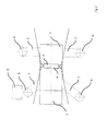
- Fig. 1 shows a vehicle 1 having a cab 2.
- an unillustrated aerial work platform which is mounted on a mounted on the vehicle 1 base.
- the aerial work platform includes, inter alia, a lifting device which is fastened to the underframe and the end of which carries a working platform, for example a basket.
- the lifting device has, for example, a multi-component, telescopic boom, at whose free end of the last component the working platform is mounted on.
- a detection device 4 is shown in the form of a camera, which detects the side area adjacent to the vehicle and on an in Fig. 1 Indicator 5, not shown, indicates.
- the display device 5 is preferably arranged in the driver's cab 2 so that a user can see the display device 5 from the driver's seat and possibly also operate it.
- Fig. 2 again represents a plan view, but here for each vehicle side a detection device 4 is located.
- the front supports at an angle not equal to 90 ° to the longitudinal axis of the vehicle 1 in the direction of the cab 2, while the rear supports are extended at a 90 ° angle to the longitudinal axis.
- the extension path 7 is shown on the widest point of the respective support 3, which is usually located in the region of the lower-side support surface 8. It is obvious that the width of the Ausfahrweges 7 seen over the height of a support 3 is not always the same.
- Fig. 2 In addition, an obstacle 9 is shown in the area of the front right support 3.
- the obstacle 9 is detected by the detection device 4 and also displayed on the display device 5.
- the user of the vehicle 1 recognizes directly that in a further retraction on the support position shown in dashed lines, the support 3 collides with the obstacle 9.
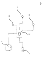
- Fig. 3 shows the components for carrying out the method.
- the detection device 4, which is designed as a camera in the illustrated example, is connected to a computer unit 10. The camera delivers still images, preferably videos, from the captured area.
- the computer unit 10 is in turn connected to the display device 5, for example a screen.
- the screen may be, for example, a touch screen.
- the display device 5 is preferably located in the immediate operating area of the user, for example in the driver's cab 2.
- the display device 5 may also be the screen of a navigation device.
- an operating unit 11 For operating each support 3, an operating unit 11 is shown.
- an actuator 12 is shown only to a support 3, which can be controlled by means of the control unit 11.
- the actuator 12 may be, for example, a hydraulic cylinder.
- the image recorded by the detection device 4 is sent to the display device 5, optionally after processing in the computer unit 10, and displayed here. If necessary, the detection device 4 and / or the display in the display device 5 can also be controlled by means of the operating unit 11.
- the computer unit 10 can also be used to calculate desired additional information, which is additionally displayed alphanumerically or graphically in the display device 5.
- a detection device 13 for example in the form of a sensor, is provided which also with the computer unit 10 is connected and detects obstacles 9 in the region of the extension path 7.
- the information of the detection device 13 are evaluated in the computer unit 10. They can also be displayed alphanumerically or graphically in the display device 5.
- the operating unit 10 can also be used to modify the signals of the detection device 13.
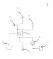
- Fig. 4 an extended embodiment is shown.
- the computer unit 10 is assigned a database 14.
- the possibility of a connection to the Internet 15 may additionally be provided.
- specific data, information or performance parameters of various support configurations may be stored.
- further data, such as location coordinates, can be queried.
- Fig. 5 the end region of a support 3 is shown, which has a detection device 13 in the region of its free end.
- the support 3 is in the direction of arrow 16 off or retractable.
- the detection device 13 When moving out the detection device 13 first detects the left obstacle 9. However, since the height of this obstacle 9 is less than the distance between the lower edge of the support surface 8 of the support 3 and the ground 17, the support 3, the left obstacle 9 during extension "over run ".
- the detection device 13 detects the further right obstacle 9, which is located in the extension path 7. Since the right obstacle 9 has a greater height, the further extension is stopped so early that a collision is prevented.
- data and / or information is a visual and / or audible warning possible. The operation can also be restricted or prevented.
- the detection device 4 is arranged in these embodiments so that it detects the vehicle 1 from above, so that all areas are displayed around the vehicle 1 around.
- Fig. 6 are at different distances far away from the vehicle 1 arranged support positions 6, the maximum allowable support forces for each support position 6 is displayed. This value is determined by the computer unit 10. In this determination, various information, boundary conditions and data, such as orientation of the vehicle 1 to the ground 17, alignment of the platform to the vehicle 1, type and payload of the lifting device, nature of the substrate 17 or the like, a.
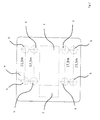
- Fig. 7 shows for each support 3 two arranged at different distances from the vehicle 1 support positions 6.
- the computer unit 10 By means of the computer unit 10 to the user in this case directly with this support position 6 maximum achievable range is displayed.
- various information, boundary conditions and data such as orientation of the vehicle 1 to the ground 17, alignment of the platform to the vehicle 1, type and payload of the lifting device, nature of the substrate 17 or the like, a. If the supports 3 are brought into the first support position 6, a reach of 17.3 m is achievable, while further extension of the support 3 allows a range of 21.5 m.
- an obstacle 9 is shown in the area of the right front support 3. The user recognizes on the display device 5 directly that the right front support 3 can not be moved to the outer support position 6, since then there is a collision.
- Fig. 8 shows the screen content when the computer unit 10 has determined directly the size of the required support surface 18.
- the size of the required support surface 18, which is generated for example by laid down on the substrate 17 wooden boards depends, inter alia, on the nature of the substrate 17 from.
Landscapes
- Engineering & Computer Science (AREA)
- Mechanical Engineering (AREA)
- Structural Engineering (AREA)
- Life Sciences & Earth Sciences (AREA)
- Geology (AREA)
- Forklifts And Lifting Vehicles (AREA)
Applications Claiming Priority (1)
| Application Number | Priority Date | Filing Date | Title |
|---|---|---|---|
| DE102014107810.1A DE102014107810A1 (de) | 2014-06-03 | 2014-06-03 | Verfahren zur Visualisierung der Abstützposition und/oder des Ausfahrweges zumindest einer Stütze eines Fahrzeuges sowie Fahrzeug mit zumindest einer Stütze |
Publications (2)
| Publication Number | Publication Date |
|---|---|
| EP2952467A1 true EP2952467A1 (fr) | 2015-12-09 |
| EP2952467A8 EP2952467A8 (fr) | 2016-02-17 |
Family
ID=53396219
Family Applications (1)
| Application Number | Title | Priority Date | Filing Date |
|---|---|---|---|
| EP15169820.6A Withdrawn EP2952467A1 (fr) | 2014-06-03 | 2015-05-29 | Procédé de visualisation de la position d'appui et/ou de la sortie d'au moins un support d'un véhicule et véhicule doté d'au moins un support |
Country Status (2)
| Country | Link |
|---|---|
| EP (1) | EP2952467A1 (fr) |
| DE (1) | DE102014107810A1 (fr) |
Cited By (3)
| Publication number | Priority date | Publication date | Assignee | Title |
|---|---|---|---|---|
| WO2017164781A1 (fr) | 2016-03-23 | 2017-09-28 | Cargotec Patenter Ab | Ensemble de manipulation de charge |
| EP3333113A1 (fr) | 2016-12-07 | 2018-06-13 | Cargotec Patenter AB | Véhicule et procédé pour un véhicule comprenant un marqueur de cible sur une image d'ensemble |
| EP3333114A1 (fr) | 2016-12-07 | 2018-06-13 | Cargotec Patenter AB | Véhicule et procédé pour un véhicule avec présentation de limitation de plage de charge maximale |
Citations (4)
| Publication number | Priority date | Publication date | Assignee | Title |
|---|---|---|---|---|
| JP2008074594A (ja) * | 2006-09-25 | 2008-04-03 | Tadano Ltd | 作業機搭載車両の周辺監視装置 |
| EP2573039A2 (fr) * | 2011-09-23 | 2013-03-27 | Manitowoc Crane Companies, LLC | Système et procédés de surveillance de stabilisateur |
| KR20140040950A (ko) * | 2012-09-27 | 2014-04-04 | 구우식 | 특수차량용 아웃트리거의 위치선정장치 |
| EP2722302A1 (fr) * | 2012-10-17 | 2014-04-23 | Iveco Magirus Ag | Véhicule utilitaire avec système de surveillance permettant de surveiller la position des stabilisateurs |
Family Cites Families (5)
| Publication number | Priority date | Publication date | Assignee | Title |
|---|---|---|---|---|
| DE3624486A1 (de) * | 1986-07-19 | 1988-01-28 | Thomas Enkelmann Computer | Verfahren und vorrichtung zur verringerung der aktiven und passiven gefaehrdung bei fahrzeugen und/oder foerdergeraeten |
| DE19934285A1 (de) * | 1999-07-21 | 2001-01-25 | Deere & Co | Teleskoplader |
| DE10138898A1 (de) * | 2000-08-30 | 2002-05-23 | Pat Gmbh | Redundantes Sicherheitssystem eines Fahrzeuges |
| DE202010014310U1 (de) * | 2010-10-14 | 2012-01-18 | Liebherr-Werk Ehingen Gmbh | Kran, insbesondere Raupen- oder Mobilkran |
| DE202014000827U1 (de) * | 2014-01-29 | 2014-07-18 | Martin Hahn | Fahrhilfeanlage zur Visualisierung verdeckter Sichtbereiche |
-
2014
- 2014-06-03 DE DE102014107810.1A patent/DE102014107810A1/de not_active Withdrawn
-
2015
- 2015-05-29 EP EP15169820.6A patent/EP2952467A1/fr not_active Withdrawn
Patent Citations (4)
| Publication number | Priority date | Publication date | Assignee | Title |
|---|---|---|---|---|
| JP2008074594A (ja) * | 2006-09-25 | 2008-04-03 | Tadano Ltd | 作業機搭載車両の周辺監視装置 |
| EP2573039A2 (fr) * | 2011-09-23 | 2013-03-27 | Manitowoc Crane Companies, LLC | Système et procédés de surveillance de stabilisateur |
| KR20140040950A (ko) * | 2012-09-27 | 2014-04-04 | 구우식 | 특수차량용 아웃트리거의 위치선정장치 |
| EP2722302A1 (fr) * | 2012-10-17 | 2014-04-23 | Iveco Magirus Ag | Véhicule utilitaire avec système de surveillance permettant de surveiller la position des stabilisateurs |
Cited By (6)
| Publication number | Priority date | Publication date | Assignee | Title |
|---|---|---|---|---|
| WO2017164781A1 (fr) | 2016-03-23 | 2017-09-28 | Cargotec Patenter Ab | Ensemble de manipulation de charge |
| EP4206113A1 (fr) | 2016-03-23 | 2023-07-05 | Hiab AB | Ensemble de manipulation de charge |
| EP3333113A1 (fr) | 2016-12-07 | 2018-06-13 | Cargotec Patenter AB | Véhicule et procédé pour un véhicule comprenant un marqueur de cible sur une image d'ensemble |
| EP3333114A1 (fr) | 2016-12-07 | 2018-06-13 | Cargotec Patenter AB | Véhicule et procédé pour un véhicule avec présentation de limitation de plage de charge maximale |
| WO2018103929A1 (fr) | 2016-12-07 | 2018-06-14 | Cargotec Patenter Ab | Véhicule et procédé pour un véhicule, avec présentation de limitation de plage de charge maximale |
| WO2018103928A1 (fr) | 2016-12-07 | 2018-06-14 | Cargotec Patenter Ab | Véhicule et procédé destiné à un véhicule, comprenant un marqueur cible sur une image d'ensemble |
Also Published As
| Publication number | Publication date |
|---|---|
| DE102014107810A1 (de) | 2015-12-03 |
| EP2952467A8 (fr) | 2016-02-17 |
Similar Documents
| Publication | Publication Date | Title |
|---|---|---|
| EP3135822B1 (fr) | Engin automobile et procede d'affichage de l'environnement d'un engin automobile | |
| EP2038493B1 (fr) | Pompe à béton automobile avec mât articulé | |
| DE112016000013B4 (de) | Steuersystem für ein Arbeitsfahrzeug, Steuerverfahren und Arbeitsfahrzeug | |
| EP3160891B1 (fr) | Manipulateur de grande taille, mobile | |
| EP3260357B1 (fr) | Véhicule comprenant un système de man uvre | |
| EP3000762B1 (fr) | Procédé de détermination optique, automatique d'une position cible pour un palonnier de conteneur | |
| DE102017120613B4 (de) | Verfahren zum Bewegen einer Last mit einem Kran | |
| DE102007046287B4 (de) | Verfahren zur Kalibrierung einer Sensoranordnung | |
| DE102022202296A1 (de) | System und verfahren zur selektiven automatisierung von beladungsvorgangs-phasen für selbstfahrende arbeitsfahrzeuge | |
| EP3853167B1 (fr) | Grue avec un dispositif anti-collision ainsi que procédé de réglage d'un tel dispositif anti-collision | |
| DE102018121014A1 (de) | Verfahren und systeme zum betreiben einer fräsmaschine | |
| WO2016016305A1 (fr) | Pompe à béton et procédé servant au fonctionnement de ladite pompe à béton | |
| DE102008020777A1 (de) | Absetzkipper mit Überladungssicherung | |
| EP2551175A2 (fr) | Remorque destinée à la surveillance du trafic | |
| DE102016119839A1 (de) | Verfahren zum automatischen Positionieren eines Portalhubstaplers für Container und Portalhubstapler dafür | |
| EP2952467A1 (fr) | Procédé de visualisation de la position d'appui et/ou de la sortie d'au moins un support d'un véhicule et véhicule doté d'au moins un support | |
| DE202005015516U1 (de) | Abstützeinrichtung für einen Mobilkran | |
| DE102007046288B4 (de) | Verfahren und Sensoranordnung zur Vermessung optischer Merkmale | |
| DE102018131220A1 (de) | Arbeitsmaschine | |
| DE102014001832A1 (de) | Pritschenaufbau für Nutzfahrzeuge | |
| EP2584097B1 (fr) | Appareil de construction | |
| DE102015016843B4 (de) | Anlernverfahren | |
| EP3959166B1 (fr) | Procédé de fonctionnement d'une grue automotrice | |
| WO2024240478A1 (fr) | Procédé et machine de travail | |
| EP4532370A1 (fr) | Système de dispositif de levage pour conteneurs de collecte de déchets, et procédé pour faire fonctionner un tel système |
Legal Events
| Date | Code | Title | Description |
|---|---|---|---|
| PUAI | Public reference made under article 153(3) epc to a published international application that has entered the european phase |
Free format text: ORIGINAL CODE: 0009012 |
|
| AK | Designated contracting states |
Kind code of ref document: A1 Designated state(s): AL AT BE BG CH CY CZ DE DK EE ES FI FR GB GR HR HU IE IS IT LI LT LU LV MC MK MT NL NO PL PT RO RS SE SI SK SM TR |
|
| AX | Request for extension of the european patent |
Extension state: BA ME |
|
| STAA | Information on the status of an ep patent application or granted ep patent |
Free format text: STATUS: THE APPLICATION IS DEEMED TO BE WITHDRAWN |
|
| 18D | Application deemed to be withdrawn |
Effective date: 20160610 |