EP2952482B1 - Vorrichtung zur aufbereitung von wasser eines gewässers - Google Patents
Vorrichtung zur aufbereitung von wasser eines gewässers Download PDFInfo
- Publication number
- EP2952482B1 EP2952482B1 EP15167514.7A EP15167514A EP2952482B1 EP 2952482 B1 EP2952482 B1 EP 2952482B1 EP 15167514 A EP15167514 A EP 15167514A EP 2952482 B1 EP2952482 B1 EP 2952482B1
- Authority
- EP
- European Patent Office
- Prior art keywords
- water
- arrangement
- pipe
- granulate
- tube
- Prior art date
- Legal status (The legal status is an assumption and is not a legal conclusion. Google has not performed a legal analysis and makes no representation as to the accuracy of the status listed.)
- Active
Links
Images
Classifications
-
- C—CHEMISTRY; METALLURGY
- C02—TREATMENT OF WATER, WASTE WATER, SEWAGE, OR SLUDGE
- C02F—TREATMENT OF WATER, WASTE WATER, SEWAGE, OR SLUDGE
- C02F1/00—Treatment of water, waste water, or sewage
- C02F1/66—Treatment of water, waste water, or sewage by neutralisation; pH adjustment
-
- B—PERFORMING OPERATIONS; TRANSPORTING
- B01—PHYSICAL OR CHEMICAL PROCESSES OR APPARATUS IN GENERAL
- B01F—MIXING, e.g. DISSOLVING, EMULSIFYING OR DISPERSING
- B01F21/00—Dissolving
- B01F21/20—Dissolving using flow mixing
- B01F21/22—Dissolving using flow mixing using additional holders in conduits, containers or pools for keeping the solid material in place, e.g. supports or receptacles
- B01F21/221—Dissolving using flow mixing using additional holders in conduits, containers or pools for keeping the solid material in place, e.g. supports or receptacles comprising constructions for blocking or redispersing undissolved solids
-
- B—PERFORMING OPERATIONS; TRANSPORTING
- B01—PHYSICAL OR CHEMICAL PROCESSES OR APPARATUS IN GENERAL
- B01F—MIXING, e.g. DISSOLVING, EMULSIFYING OR DISPERSING
- B01F21/00—Dissolving
- B01F21/50—Elements used for separating or keeping undissolved material in the mixer
- B01F21/504—Sieves, i.e. perforated plates or walls
-
- C—CHEMISTRY; METALLURGY
- C02—TREATMENT OF WATER, WASTE WATER, SEWAGE, OR SLUDGE
- C02F—TREATMENT OF WATER, WASTE WATER, SEWAGE, OR SLUDGE
- C02F1/00—Treatment of water, waste water, or sewage
- C02F1/68—Treatment of water, waste water, or sewage by addition of specified substances, e.g. trace elements, for ameliorating potable water
- C02F1/685—Devices for dosing the additives
- C02F1/687—Devices for dosing solid compounds
-
- C—CHEMISTRY; METALLURGY
- C02—TREATMENT OF WATER, WASTE WATER, SEWAGE, OR SLUDGE
- C02F—TREATMENT OF WATER, WASTE WATER, SEWAGE, OR SLUDGE
- C02F1/00—Treatment of water, waste water, or sewage
- C02F1/68—Treatment of water, waste water, or sewage by addition of specified substances, e.g. trace elements, for ameliorating potable water
- C02F1/685—Devices for dosing the additives
- C02F1/688—Devices in which the water progressively dissolves a solid compound
-
- C—CHEMISTRY; METALLURGY
- C02—TREATMENT OF WATER, WASTE WATER, SEWAGE, OR SLUDGE
- C02F—TREATMENT OF WATER, WASTE WATER, SEWAGE, OR SLUDGE
- C02F2103/00—Nature of the water, waste water, sewage or sludge to be treated
- C02F2103/007—Contaminated open waterways, rivers, lakes or ponds
Definitions
- the invention relates to a device for the treatment of water of a body of water.
- the device has a tube, with which the water can be sucked from the lower layers of the water and then conveyed upwards.
- the upper end of the tube is located below the water surface.
- the operation of the paddle wheel can be accomplished for example by means of a photovoltaic system.
- US 5,256,309 discloses a dissolution vessel connected to a water pumping unit.
- the dissolution vessel includes slaked lime.
- US 5,185,085 discloses a method for adding a neutralizer by means of a boat. Surface water is drawn in to be routed to a depth of more than 15 feet below the surface of the water.
- DE 200 11 300 U1 discloses a reactor for purifying liquid.
- the reactor vessel is filled with a granulated limestone. Through an overflow outlet, the water that has passed in reaction with the granulated limestone can re-enter the water.
- GB 2 243 151 A discloses a water-cleaning device utilizing a water-lifter.
- the object of the invention is to provide a device for water treatment, with which a further improvement of the water quality of the water body can be achieved.
- the invention solves this problem by a device according to claim 1.
- the device for treating water from a body of water is provided with a first arrangement, with which the water of the water can be conveyed upwards through a pipe. Furthermore, a second arrangement is present, which contains a calcareous granules, on which the water can flow past, so that the water can absorb lime particles. With the aid of the second arrangement, it is possible to deacidify the water by means of the lime particles. If the body of water is a so-called acidic body of water, the water of which therefore has an acid pH, an improvement in the quality of the water can be achieved with the aid of the invention.
- the second arrangement is arranged in the area of the water surface of the water body.
- a trough is provided, in which the granules is contained, which is connected to the tube, and through which the water can be passed.
- the water is therefore preferably sucked in from the bottom of the water and conveyed upwards into the area of the water surface. There, the water flows through the tub and thus the granules. In this way, the water absorbs lime particles, which are then released together with the water back into the water. This results in a circulation of water and lime particles, which in turn leads to a uniform deacidification of the water.
- the second arrangement expediently has a conveying device with which the water can be conveyed from the pipe in the direction of an outlet and can be released into the water in the area of the water surface.
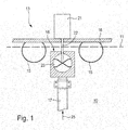
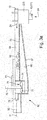
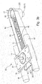
- FIGS. 1 . 3a and 3b show a schematic side view and a perspective view of an embodiment of an apparatus for treating water of a body of water.
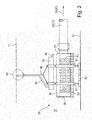
- FIG. 2 shows an arrangement which is not the subject of the invention.
- a body of water 10 shown which is in particular a stagnant water.
- the water surface of the water body 10 is identified by the reference numeral 11.
- a first arrangement 13 On the water surface 11 of the water body 10 floats a first arrangement 13, which is provided for the suction of water.
- the arrangement 13 has a platform 16 supported by floats 15.
- a tube 17 On the underside of the platform 16, a tube 17 is arranged, which extends in an approximately vertical direction within the water body 10 downwards.
- the upper end 18 of the tube 17 is located below the water surface 11 and thus in the water.
- the upper end 18 is arranged approximately 10 cm below the water surface 11, but may optionally also be up to 100 cm below the water surface 11.
- an electric motor 21 is mounted, which drives a paddle wheel 23 via a shaft 22.
- the shaft 22 is approximately coaxial with the tube 17 and extends from the electric motor 21 to the upper portion of the tube 17.
- the paddle wheel 23 is disposed inside the tube 17 below the upper end 18.
- the paddle wheel 23 is fixed to the free end of the shaft 22 and thus can rotate about an axis extending approximately coaxially with the tube 17.
- the paddle wheel 23 is driven so that the water in the tube 17 is moved upward. This is in the FIG. 1 indicated by the arrow 25. This makes it possible to promote water from the deeper layers of the water body 10 upwards.
- the distributed Promoted water into the environment and connects there with the existing in the upper layers of the water body 10. Due to the promotion of water upwards at the same time decreases water from the upper layers of the water body 10 downwards. This results in a total circulation of the water in the vertical direction in the water 10 result.
- the above based on the FIG. 1 described first arrangement 13 substantially corresponds to the arrangement of the above-mentioned DE 20 2004 008 003 U1 ,
- FIG. 2 there is shown a second arrangement 30 which does not fall within the scope of the present claims.
- the second arrangement 30 is arranged at the bottom of the water body 10.
- the water surface is like in the FIG. 1 designated by the reference numeral 11 and the bottom of the water body 10 is indicated by the reference numeral 31.
- the second arrangement 30 comprises a tube 33, is sucked through the water, wherein the direction of the water in the FIG. 2 is indicated by the reference numeral 34.
- the way in which the water is sucked in is not essential.
- the second arrangement 30 can, for example, with the first arrangement 13 of FIG. 1 be connected.
- the two assemblies 13, 30 are connected to each other via the tube 17 and the water is sucked through the tube 17 according to the arrow 25.
- the reference numerals 17 and 25 are in the FIG. 2 in brackets.
- the tube 33 is connected to a material container 36, which may have any shape per se.
- the material container 36 is liquid-tightly connected to the tube 33. Furthermore, the material container 36 has an area which is provided with openings or the like, so that water can enter from the outside into the interior of the material container 36.
- the material container 36 may be cylindrical or tubular.
- the material container 36 is connected at one of its two end faces, for example via a disc-shaped intermediate part 37 and with the aid of pipe clips or the like to the tube 33.
- a disc-shaped plate 38 having a plurality of holes.
- the plate 38 is screwed to the material container 36, for example.
- the diameters of the holes in the plate 38 are selected such that water can enter from outside to inside the material container 36.
- Two clamps 41 are connected by way of example to the material container 36.
- the clamps 41 may be screwed to the material container 36 or even form a clamping connection with the material container 36.
- a weight 42 for example a stone slab or the like, is firmly connected below the material container 36. This in turn can be done by a screw or otherwise.
- the buoyancy tank 43 can by a Screw connection or otherwise be firmly connected to the clamps 41.
- the buoyancy tank 43 may for example be cylindrical or tubular and closed liquid-tight at its two end faces with disc-shaped plates or the like.
- the buoyancy tank 43 is connected on the one hand to one end of a hose 45 and on the other hand has a valve 46.
- the hose 45 has a length which corresponds approximately to the water depth of the water body 10.
- the buoyancy tank 43 can be filled with a gas, for example with air.
- the valve 46 the buoyancy tank 43 can be filled with water.
- the cable 48 has a length which corresponds approximately to the water depth of the water body 10.
- the other end of the cable 48 is attached to a buoy 49, which floats on the water surface 11 of the water body 10. At the buoy 49 and the other end of the tube 45 is held.
- the material container 36 is filled with granules 51.
- the granules 51 may be a coarse-grained calcareous granulate, for example so-called lime fracture, ie calcareous, coarsely fractured limestone.
- the granules 51 may also be fine-grained lime granules.
- the granules 51 may be loosely contained in the material container 36, or may be contained in, for example, a liquid-permeable bag or the like located in the material container 36.
- the granules 51 are present in the material container 36 such that the water sucked through the plate 38 into the interior of the material container 36 moves along the granules 51 in the direction of the tube 33.
- the granules 51 is thus arranged so that the water at its flow through the material container 36 comes into contact with the granules 51.
- a perforated plate 53 may be present in the material container 36. If present, the perforated plate 53 is arranged in the region of the bottom of the material container 36 such that it extends approximately parallel to the bottom 31 of the body of water 10. With a flow of water through the material container 36 smaller debris or the like contained in the water through the granules 51 and through the perforated plate 53 through the bottom of the material container 36 and remain there. However, the granules 51 can not substantially pass through the perforated plate 53.
- the material container 36 can be filled with the granules 51 and the valve 46 can be opened.
- the plate 38 can be unscrewed and screwed back after filling. Thereafter, the assembly 30 can be placed in the water, the buoy 49 remains with the end of the hose 45 and the end of the rope 48 on the water surface 11.
- the assembly 30 Due to the weight 42 and the granules 51 as well as due to the open valve 46, the assembly 30 is lowered in the water 10 down. Eventually in the buoyancy tank 43 existing air escapes and the buoyancy tank 43 runs full of water. The assembly 30 then comes to rest with the weight 42 at the bottom of the body of water 10. In this state, the assembly 30 is thus at the bottom 31 of the body of water 10 and is connected via the hose 46 and the cable 48 to the buoy 49.
- water can be sucked in via the tube 33 in the direction of the arrow 34. This can be performed for example with the aid of the first arrangement 13.
- the water with the lime particles contained therein is conveyed upwards, for example with the aid of the arrangement 13, in the body of water 10 and flows back into the body of water 10 in the area of the water surface 11.
- the lime particles contained in the water are thus transported to the water surface 11, from where they sink back down.
- circulation of the water within the body of water 10 occur, but also the lime particles circulate in the body of water 10.
- the body of water 10 is a so-called acidic water, the water of which therefore has an acidic pH
- the aid of the described arrangement 30 and with the aid of the procedure described above to deacidify the water by means of the lime particles.
- an improvement in the quality of the water can be achieved.
- the second arrangement 30 in the body of water 10 can be raised upward.
- the location where the second assembly 30 is present in the body of water 10 can be determined by the buoy 49.
- Air is then pumped into the buoyancy tank 43 via the end of the hose 45 accessible to the buoy 49. This can be done, for example, from a boat with the help of a pump. about the valve 46 displaces the water from the buoyancy tank 43, so that the buoyancy tank 43 is slowly filled with air.
- the entire assembly 30 is lifted from the buoyancy tank 43 upwards.
- the arrangement 30 rises to the water surface 11. It can now be closed, the valve 46 and optionally also the upper end of the tube 45 are closed with a plug or the like, so that the assembly 30 does not sink again, but is held substantially on the water surface 11.
- the assembly 30 can be lowered back to the bottom 31 of the water body 10, after the valve 46 has been opened again and the optional plug has been removed again.
- the arrangement 30 can also be accommodated in the boat, for example, so that the maintenance is carried out there or the material container 36 is filled with the granules 51. If necessary, can then be dispensed with the valve 46 and the plug.
- the second arrangement 30 need not necessarily be arranged on the bottom 31 of the body of water 10, but may also be arranged between the bottom 31 and the water surface. This can be achieved by a corresponding weight 42 and / or a correspondingly filled with air buoyancy tank 43. Also in this case, a deacidification of the water body 10 is achieved because the votes from the second assembly 30 lime particles fall to the bottom 31 of the water.
- FIGS. 3a . 3b an arrangement 60 according to the invention is shown.
- the arrangement 60 is - in Difference to the arrangement 30 of the FIG. 2 - Not arranged on the bottom 31 of the water body 10, but in the area of the water surface 11th
- the second arrangement 60 has a tube 63 through which water is drawn in, the direction of the water in the FIG. 3a indicated by the reference numeral 64.
- the way in which the water is sucked in is - as already mentioned - not essential.
- the second arrangement 60 is connected to the first arrangement 13 of FIG. 1 connected.
- the two assemblies 13, 60 are coupled to each other via the tube 17 and the paddle wheel 23.
- the reference numerals 17 and 23 are in the FIGS. 3a . 3b in brackets.
- the second arrangement 60 has a trough 66 which is constructed from a bottom 67 and two side walls 68.
- the tub 66 may have a lid; but this is not necessary, which is why in the FIGS. 3a . 3b no lid is shown.
- the trough 66 forms a cuboid whose length is substantially greater than its height and is also greater than its width.
- the bottom 67 and the two side walls 68 of the trough 66 are each formed approximately rectangular and the two side walls 68 of the trough 66 are aligned approximately parallel to each other.
- a perforated plate 70 is present, which extends approximately in the same direction as the bottom 67. From the FIG. 3a it can be seen that the bottom 67 and the trough 70 can also be aligned at an angle to each other.
- the perforated plate 70 is secured in the trough 66 such that above and below the perforated plate 70 water may be present in the trough 66.
- the perforated plate 70 extends over the entire length and width of the trough 66.
- the trough 66 is liquid-tightly connected at one end to the tube 63.
- the connection is arranged such that the water, which is sucked through the tube 63 in the direction of the arrow 64, flows above the perforated plate 70 into the trough 66.
- FIGS. 3a . 3b it is a wall 72 which is semicircular and extends from one to the other side wall 68 of the trough 66.
- the wall 72 may on the one hand be connected directly to the tube 63.
- the wall 72 is indirectly connected via the housing of the paddle wheel 23 with the tube 63.
- the trough 66 has a conveyor 74 and an outlet 75.
- the conveying device 74 is designed such that water is conveyed from the region below the perforated plate 70 in the direction of the outlet 75.
- the conveyor 74 may be, for example, a shaft 76 and a paddle wheel 77, which may for example be driven by an unillustrated electric motor.
- the impeller 77 may be surrounded by a tubular wall 78 which extends on the one hand in the region of the trough 66 below the perforated plate 70 and is open there, and on the other hand extends in the direction of the outlet 75 and is connected thereto.
- the wall 78 and the shaft 76 are aligned in an approximately vertical direction.
- a float 80 is attached in each case.
- the trough 66 floats on the water 10 and is thus oriented approximately horizontally.
- the outlet 75 is located approximately in the region of the water surface 11 of the water body 10.
- the floats 80 and the outlet 75 are arranged such that, as in the FIG. 3a illustrated, the outlet 75 is located only slightly below the water surface 11 and the water surface 11 is located in the vertical direction approximately in the center of the outlet 75.
- the two floats 80 may be connected to each other via a plate 81, wherein on or on the plate 81 then components of the conveyor 74, such as the mentioned electric motor, may be attached.
- the trough 66 namely the area above the perforated plate 70, is filled with a granulate 82.
- the granulate 82 may be a coarse-grained calcareous granulate, for example so-called lime fracture, ie calcareous, coarse fractured limestone.
- the granules 82 may also be fine-grained lime granules.
- the granules 82 may be loosely present on the perforated plate 70, or may be contained, for example, in a liquid-permeable bag or the like disposed on the perforated plate 70.
- water can be drawn from the water 10 in the direction of the arrow 64 and conveyed through the pipe 63. This water then flows into the tub 66, in the area above the perforated plate 70. This is in the FIGS. 3a . 3b indicated by an arrow 84. The water then flows past the granules 82 and passes through the perforated plate 70 into the region of the trough 66, which is located below the perforated plate 70. From there, the water is conveyed by means of the conveyor 74 in the direction of the outlet 75 and then flows from the outlet 75 back into the water 10. The latter is in the FIG. 3b indicated by arrows 85.
- the water may leach and absorb lime particles from the granules 82. These lime particles are thus conveyed together with the water in the direction of the outlet 75 and discharged according to the arrow 85 into the water 10. The lime particles contained in the water thus flow into the area of the water surface 11, from where they can sink down again. There is thus a circulation of lime particles in the body of water 10.
- the body of water 10 is a so-called acidic water, the water of which therefore has an acid pH
- the aid of the described second arrangement 60 and with the aid of the procedure described above to deacidify the water by means of the lime particles.
- an improvement in the quality of the water can be achieved.
- the water does not necessarily have to be sucked in from the bottom 31 of the water body 10, but can also be sucked in from an area between the bottom 31 and the water surface 11. Also in this case, a deacidification of the water body 10 is achieved because the votes from the second arrangement 60 lime particles fall to the bottom 31 of the water body.
- the first arrangement may then in particular have a plurality of tubes 63, via which water from different regions of the body of water can be sucked in, and to which in each case one of the second arrangements 60 is connected.
- the components of the first and second assemblies 13, 30, 60 may preferably be made of sheets, such as stainless steel sheets. Optionally, at least some of the components may also be made of plastic.
- the entire water treatment apparatus may preferably be disposed on an island formed by floats or the like in the body of water 10.
- the electric motor 21 of the first arrangement 13 and the optional electric motor for driving the conveyor 74 of the second arrangement 60 can preferably be operated by means of a photovoltaic power generation system.
Landscapes
- Chemical & Material Sciences (AREA)
- Chemical Kinetics & Catalysis (AREA)
- Life Sciences & Earth Sciences (AREA)
- Hydrology & Water Resources (AREA)
- Engineering & Computer Science (AREA)
- Environmental & Geological Engineering (AREA)
- Water Supply & Treatment (AREA)
- Organic Chemistry (AREA)
- Health & Medical Sciences (AREA)
- Medicinal Chemistry (AREA)
- Separation Of Suspended Particles By Flocculating Agents (AREA)
- Physical Water Treatments (AREA)
- Aeration Devices For Treatment Of Activated Polluted Sludge (AREA)
Description
- Die Erfindung betrifft eine Vorrichtung zur Aufbereitung von Wasser eines Gewässers.
- Aus der
DE 20 2004 008 003 U1 ist eine Vorrichtung bekannt, mit der Wasser in einem Gewässer zirkuliert werden kann. Auf diese Weise kann die Qualität des Wassers, insbesondere der Sauerstoffgehalt des Wassers, verbessert werden. - Die Vorrichtung weist ein Rohr auf, mit dem das Wasser aus den unteren Schichten des Gewässers angesaugt und dann nach oben gefördert werden kann. Das obere Ende des Rohrs ist unterhalb der Wasseroberfläche angeordnet. Dort ist auch ein elektrisch angetriebenes Schaufelrad vorhanden, mit dem das Wasser in dem Rohr nach oben gefördert werden kann. Das angesaugte Wasser muss damit nicht über die Wasseroberfläche angehoben werden. Der Betrieb des Schaufelrads kann beispielsweise mit Hilfe einer photovoltaischen Anlage bewerkstelligt werden.
-
DE 199 33 181 A1 betrifft ein Verfahren zur Aufbereitung und Reinhaltung von Wasser. Einem außer Kontrolle geratenen Gewässer wird Kalkstein und/oder Kalklösung zugesetzt. Über eine Rohrleitung wird Wasser aus dem See hoch gepumpt, rieselt durch gelochte Rieselrohre auf die Kalksteine und gelangt an der Unterseite des Turms erneut in den See. -
US 5,256,309 offenbart eine dissolution vessel, welche mit einer water pumping unit verbunden ist. Die dissolution vessel umfasst slaked lime. -
US 5,185,085 offenbart ein Verfahren zum Hinzufügen eines Neutralisiers mittels eines Bootes. Oberflächenwasser wird angesaugt, um in eine Tiefe von mehr als 15 Fuß unterhalb der Wasseroberfläche geführt zu werden. -
DE 200 11 300 U1 offenbart einen Reaktor zur Reinigung von Flüssigkeit. Der Reaktorbehälter ist mit einem granulierten Kalkstein gefüllt. Durch einen Überlaufauslass kann das in Reaktion mit dem granulierten Kalkstein getretene Wasser wieder in das Gewässer gelangen. -
GB 2 243 151 A - Aufgabe der Erfindung ist es, eine Vorrichtung zur WasserAufbereitung zu schaffen, mit der eine weitere Verbesserung der Wasserqualität des Gewässers erreichbar ist.
- Die Erfindung löst diese Aufgabe durch eine Vorrichtung nach dem Anspruch 1.
- Erfindungsgemäß ist die Vorrichtung zur Aufbereitung von Wasser eines Gewässers mit einer ersten Anordnung versehen, mit der das Wasser des Gewässers durch ein Rohr nach oben förderbar ist. Weiterhin ist eine zweite Anordnung vorhanden, die ein kalkhaltiges Granulat enthält, an dem das Wasser vorbeiströmen kann, so dass das Wasser Kalkteilchen aufnehmen kann. Mit Hilfe der zweiten Anordnung ist es möglich, das Wasser mittels der Kalkteilchen zu entsäuern. Handelt es sich bei dem Gewässer um ein sogenanntes saures Gewässer, dessen Wasser also einen sauren ph-Wert aufweist, so kann mit Hilfe der Erfindung eine Verbesserung der Qualität des Wassers erreicht werden.
- Die zweite Anordnung ist im Bereich der Wasseroberfläche des Gewässers angeordnet. Erfindungsgemäß ist eine Wanne vorgesehen, in der das Granulat enthalten ist, die mit dem Rohr verbunden ist, und durch die das Wasser hindurchführbar ist. Das Wasser wird also vorzugsweise vom Grund des Gewässers angesaugt und nach oben in den Bereich der Wasseroberfläche gefördert. Dort durchströmt das Wasser die Wanne und damit das Granulat. Auf diese Weise nimmt das Wasser Kalkteilchen auf, die dann zusammen mit dem Wasser wieder in das Gewässer abgegeben werden. Es entsteht somit eine Zirkulation des Wassers und der Kalkteilchen, was wiederum zu einer gleichmäßigen Entsäuerung des Gewässers führt.
- Die zweite Anordnung weist zweckmäßigerweise eine Fördereinrichtung auf, mit der das Wasser von dem Rohr in Richtung zu einem Auslass förderbar und im Bereich der Wasseroberfläche in das Gewässer abgebbar ist.
- Die
Figuren 1 ,3a und3b zeigen eine schematische Seitenansicht und eine Perspektivdarstellung einer Ausführungsform einer Vorrichtung zum Aufbereiten von Wasser eines Gewässers. - Die
Figur 2 zeigt eine Anordnung, die nicht Gegenstand der Erfindung ist. In derFigur 1 ist ein Gewässer 10 dargestellt, bei dem es sich insbesondere um ein stehendes Gewässer handelt. Die Wasseroberfläche des Gewässers 10 ist mit dem Bezugszeichen 11 gekennzeichnet. - Auf der Wasseroberfläche 11 des Gewässers 10 schwimmt eine erste Anordnung 13, die zum Ansaugen von Wasser vorgesehen ist. Die Anordnung 13 weist eine von Schwimmern 15 getragene Plattform 16 auf. Auf der Unterseite der Plattform 16 ist ein Rohr 17 angeordnet, das sich in etwa vertikaler Richtung innerhalb des Gewässers 10 nach unten erstreckt. Das obere Ende 18 des Rohrs 17 befindet sich unterhalb der Wasseroberfläche 11 und damit im Wasser. Das obere Ende 18 ist etwa 10 cm unterhalb der Wasseroberfläche 11 angeordnet, kann sich aber gegebenenfalls auch bis zu 100 cm unterhalb der Wasseroberfläche 11 befinden.
- Auf der Plattform 16 ist ein Elektromotor 21 montiert, der über eine Welle 22 ein Schaufelrad 23 antreibt. Die Welle 22 verläuft etwa koaxial zu dem Rohr 17 und erstreckt sich von dem Elektromotor 21 bis in den oberen Bereich des Rohrs 17. Das Schaufelrad 23 ist im Inneren des Rohrs 17 unterhalb des oberen Endes 18 angeordnet. Das Schaufelrad 23 ist an dem freien Ende der Welle 22 befestigt und kann damit um eine etwa koaxial zum Rohr 17 verlaufende Achse rotieren.
- Das Schaufelrad 23 wird derart angetrieben, dass das Wasser in dem Rohr 17 nach oben bewegt wird. Dies ist in der
Figur 1 durch den Pfeil 25 angedeutet. Damit ist es möglich, Wasser aus den tieferen Schichten des Gewässers 10 nach oben zu fördern. Am oberen Ende 18 des Rohrs 17 verteilt sich das geförderte Wasser in die Umgebung und verbindet sich dort mit dem in den oberen Schichten des Gewässers 10 vorhandenen Wasser. Aufgrund der Förderung von Wasser nach oben sinkt gleichzeitig Wasser aus den oberen Schichten des Gewässers 10 nach unten ab. Dies hat insgesamt eine Zirkulation des Wassers in vertikaler Richtung in dem Gewässer 10 zur Folge. - Die vorstehend anhand der
Figur 1 beschriebene erste Anordnung 13 entspricht im Wesentlichen der Anordnung der eingangs bereits erwähntenDE 20 2004 008 003 U1 . - In der
Figur 2 ist eine zweite Anordnung 30 dargestellt, die nicht unter die vorliegenden Ansprüche fällt. Die zweite Anordnung 30 ist am Grund des Gewässers 10 angeordnet. Die Wasseroberfläche ist wie in derFigur 1 mit dem Bezugszeichen 11 gekennzeichnet und der Grund des Gewässers 10 ist mit dem Bezugszeichen 31 gekennzeichnet. - Die zweite Anordnung 30 weist ein Rohr 33 auf, durch das Wasser angesaugt wird, wobei die Richtung des Wassers in der
Figur 2 mit dem Bezugszeichen 34 angedeutet ist. Die Art und Weise, wie das Wasser angesaugt wird, ist dabei nicht wesentlich. - Die zweite Anordnung 30 kann beispielsweise mit der ersten Anordnung 13 der
Figur 1 verbunden sein. In diesem Fall sind die beiden Anordnungen 13, 30 über das Rohr 17 miteinander verbunden und das Wasser wird entsprechend dem Pfeil 25 durch das Rohr 17 angesaugt. Die Bezugszeichen 17 und 25 sind in derFigur 2 in Klammern angegeben. - Nachfolgend wird von dem erstgenannten, allgemeinen Fall ausgegangen, bei dem das Wasser auf beliebige Weise durch das Rohr 33 in Richtung des Pfeils 34 angesaugt wird.
- Das Rohr 33 ist mit einem Materialbehälter 36 verbunden, der an sich jegliche Gestalt besitzen kann. Der Materialbehälter 36 ist flüssigkeitsdicht mit dem Rohr 33 verbunden. Weiterhin weist der Materialbehälter 36 einen Bereich auf, der mit Öffnungen oder dergleichen versehen ist, so dass Wasser von außen in den Innenraum des Materialbehälters 36 eintreten kann.
- Wie dies in der
Figur 2 beispielhaft dargestellt ist, kann der Materialbehälter 36 zylindrisch oder rohrförmig ausgebildet sein. In diesem Fall ist der Materialbehälter 36 an einer seiner beiden Stirnseiten beispielsweise über ein scheibenförmiges Zwischenteil 37 und mit Hilfe von Rohrschellen oder dergleichen mit dem Rohr 33 verbunden. An der anderen Stirnseite ist der Materialbehälter 36 mit einer scheibenförmigen Platte 38 versehen, die eine Mehrzahl von Bohrungen aufweist. Die Platte 38 ist mit dem Materialbehälter 36 beispielsweise verschraubt. Die Durchmesser der Bohrungen in der Platte 38 sind derart gewählt, dass Wasser von außen nach innen in den Materialbehälter 36 eintreten kann. - Mit dem Materialbehälter 36 sind beispielhaft zwei Schellen 41 verbunden. Die Schellen 41 können mit dem Materialbehälter 36 verschraubt sein oder auch nur eine Klemmverbindung mit dem Materialbehälter 36 bilden. Mit den Schellen 41 ist unterhalb des Materialbehälters 36 ein Gewicht 42, beispielsweise eine Steinplatte oder dergleichen, fest verbunden. Dies kann wiederum durch eine Verschraubung oder auf sonstige Weise erfolgen.
- Oberhalb des Materialbehälters 36 ist ein Auftriebsbehälter 43 vorhanden. Der Auftriebsbehälter 43 kann durch eine Verschraubung oder auf sonstige Weise mit den Schellen 41 fest verbunden sein. Der Auftriebsbehälter 43 kann beispielsweise zylindrisch oder rohrförmig ausgebildet und an seinen beiden Stirnseiten mit scheibenförmigen Platten oder dergleichen flüssigkeitsdicht verschlossen sein.
- Der Auftriebsbehälter 43 ist einerseits mit einem Ende eines Schlauchs 45 verbunden und weist andererseits ein Ventil 46 auf. Der Schlauch 45 besitzt eine Länge, die etwa der Wassertiefe des Gewässers 10 entspricht. Über den Schlauch 45 kann der Auftriebsbehälter 43 mit einem Gas, beispielsweise mit Luft befüllt werden. Über das Ventil 46 kann der Auftriebsbehälter 43 mit Wasser befüllt werden.
- An den Schellen 41 ist mindestens ein Ende eines Seils 48 befestigt. Das Seil 48 besitzt eine Länge, die etwa der Wassertiefe des Gewässers 10 entspricht. Das andere Ende des Seils 48 ist an einer Boje 49 befestigt, die auf der Wasseroberfläche 11 des Gewässers 10 schwimmt. An der Boje 49 ist auch das andere Ende des Schlauchs 45 gehalten.
- Der Materialbehälter 36 ist mit einem Granulat 51 befüllt. Bei dem Granulat 51 kann es sich um ein grobkörniges kalkhaltiges Granulat handeln, beispielsweise um sogenannten Kalkbruch, also kalkhaltiges, grob gebrochenes Kalkgestein. Bei dem Granulat 51 kann es sich auch um feinkörniges Kalk-Granulat handeln. Das Granulat 51 kann lose in dem Materialbehälter 36 vorhanden sein, oder es kann beispielsweise in einem flüssigkeitsdurchlässigen Sack oder dergleichen enthalten sein, der sich in dem Materialbehälter 36 befindet.
- Das Granulat 51 ist derart in dem Materialbehälter 36 vorhanden, dass das Wasser, das durch die Platte 38 in den Innenraum des Materialbehälters 36 angesaugt wird, sich an dem Granulat 51 in Richtung zu dem Rohr 33 entlangbewegt. Das Granulat 51 ist also derart angeordnet, dass das Wasser bei seinem Durchfluss durch den Materialbehälter 36 mit dem Granulat 51 in Berührung kommt.
- In dem Materialbehälter 36 kann eine Lochplatte 53 vorhanden sein. Sofern vorhanden, so ist die Lochplatte 53 im Bereich des Bodens des Materialbehälters 36 derart angeordnet, dass sie sich etwa parallel zum Grund 31 des Gewässers 10 erstreckt. Bei einem Durchfluss von Wasser durch den Materialbehälter 36 können kleinere Schmutzteilchen oder dergleichen, die in dem Wasser enthalten sind, durch das Granulat 51 und durch die Lochplatte 53 hindurch zum Boden des Materialbehälters 36 absinken und dort liegen bleiben. Das Granulat 51 kann jedoch im Wesentlichen nicht durch die Lochplatte 53 hindurchtreten.
- Es wird nunmehr davon ausgegangen, dass die zweite Anordnung 30 aus dem Wasser entnommen ist. Damit kann der Materialbehälter 36 mit dem Granulat 51 befüllt und das Ventil 46 geöffnet werden. Zum Befüllen des Materialbehälters 36 kann die Platte 38 abgeschraubt und nach dem Befüllen wieder angeschraubt werden. Danach kann die Anordnung 30 in das Wasser abgesetzt werden, wobei die Boje 49 mit dem Ende des Schlauchs 45 und dem Ende des Seils 48 auf der Wasseroberfläche 11 verbleibt.
- Aufgrund des Gewichts 42 und des Granulats 51 sowie aufgrund des geöffneten Ventils 46 sinkt die Anordnung 30 in dem Gewässer 10 nach unten. Eventuell in dem Auftriebsbehälter 43 vorhandene Luft entweicht und der Auftriebsbehälter 43 läuft mit Wasser voll. Die Anordnung 30 kommt dann mit dem Gewicht 42 auf dem Grund des Gewässers 10 zum Stehen. In diesem Zustand befindet sich die Anordnung 30 somit am Grund 31 des Gewässers 10 und ist über den Schlauch 46 und das Seil 48 mit der Boje 49 verbunden.
- Wie eingangs bereits erwähnt wurde, kann über das Rohr 33 Wasser in Richtung des Pfeils 34 angesaugt werden. Dies kann beispielsweise mit Hilfe der ersten Anordnung 13 durchgeführt werden.
- Wird Wasser angesaugt, so tritt das Wasser von außen durch die Platte 38 hindurch in den Innenraum des Materialbehälters 36 und wird durch den Materialbehälter 36 hindurch in Richtung zu dem Rohr 33 gesaugt. Das Wasser strömt damit an dem Granulat 51 vorbei. Bei diesem Vorbeiströmen kann das Wasser Kalkteilchen aus dem Granulat 51 herauslösen und aufnehmen. Diese Kalkteilchen werden somit zusammen mit dem Wasser in Richtung des Pfeils 34 gesaugt.
- Das Wasser mit den darin enthaltenen Kalkteilchen wird beispielsweise mit Hilfe der Anordnung 13 in dem Gewässer 10 nach oben gefördert und fließt im Bereich der Wasseroberfläche 11 wieder in das Gewässer 10 zurück. Die in dem Wasser enthaltenen Kalkteilchen werden somit an die Wasseroberfläche 11 transportiert, von wo sie wieder nach unten absinken. Es entsteht somit nicht nur eine Zirkulation des Wassers innerhalb des Gewässers 10, sondern auch die Kalkteilchen zirkulieren in dem Gewässer 10.
- Handelt es sich bei dem Gewässer 10 um ein sogenanntes saures Gewässer, dessen Wasser also einen sauren ph-Wert aufweist, so ist es mit Hilfe der beschriebenen Anordnung 30 und mit Hilfe des vorstehend beschriebenen Vorgehens möglich, das Wasser mittels der Kalkteilchen zu entsäuern. Damit kann eine Verbesserung der Qualität des Wassers erreicht werden.
- Zur Wartung der zweiten Anordnung 30 und/oder zum Austausch des Granulats 51 kann die zweite Anordnung 30 in dem Gewässer 10 nach oben angehoben werden. Der Ort, wo die zweite Anordnung 30 in dem Gewässer 10 vorhanden ist, kann dabei anhand der Boje 49 festgestellt werden. Über das an der Boje 49 zugängliche Ende des Schlauchs 45 wird dann Luft in den Auftriebsbehälter 43 gepumpt. Dies kann beispielsweise von einem Boot aus mit Hilfe einer Pumpe durchgeführt werden. Über das Ventil 46 wird das Wasser aus dem Auftriebsbehälter 43 verdrängt, so dass der Auftriebsbehälter 43 langsam mit Luft gefüllt wird.
- Ist ausreichend Luft in dem Auftriebsbehälter 43 vorhanden, so wird die gesamte Anordnung 30 von dem Auftriebsbehälter 43 nach oben angehoben. Die Anordnung 30 steigt zur Wasseroberfläche 11 auf. Es kann nunmehr das Ventil 46 geschlossen werden und gegebenenfalls auch das obere Ende des Schlauchs 45 mit einem Stopfen oder dergleichen verschlossen werden, so dass die Anordnung 30 nicht wieder absinkt, sondern im Wesentlichen an der Wasseroberfläche 11 gehalten wird. Nach der Wartung bzw. nach dem Austausch des Granulats 51 kann die Anordnung 30 wieder auf den Grund 31 des Gewässers 10 abgesenkt werden, nachdem das Ventil 46 wieder geöffnet und der gegebenenfalls vorhandene Stopfen wieder entfernt worden ist.
- Alternativ kann die Anordnung 30 auch beispielsweise in das Boot aufgenommen werden, damit dort die Wartung durchgeführt wird oder der Materialbehälter 36 mit dem Granulat 51 befüllt wird. Gegebenenfalls kann dann auf das Ventil 46 und den Stopfen verzichtet werden.
- Es wird darauf hingewiesen, dass die zweite Anordnung 30 nicht zwingend auf dem Grund 31 des Gewässers 10 angeordnet sein muss, sondern auch zwischen dem Grund 31 und der Wasseroberfläche angeordnet sein kann. Dies kann durch ein entsprechendes Gewicht 42 und/oder einen entsprechend mit Luft befüllten Auftriebsbehälter 43 erreicht werden. Auch in diesem Fall wird eine Entsäuerung des Gewässers 10 erreicht, da die aus der zweiten Anordnung 30 abgegebenen Kalkteilchen auf den Grund 31 des Gewässers absinken.
- In den
Figuren 3a ,3b ist eine erfindungsgemäße Anordnung 60 dargestellt. Die Anordnung 60 ist - im Unterschied zu der Anordnung 30 derFigur 2 - nicht am Grund 31 des Gewässers 10 angeordnet, sondern im Bereich der Wasseroberfläche 11. - Die zweite Anordnung 60 weist ein Rohr 63 auf, durch das Wasser angesaugt wird, wobei die Richtung des Wassers in der
Figur 3a mit dem Bezugszeichen 64 angedeutet ist. Die Art und Weise, wie das Wasser angesaugt wird, ist dabei - wie bereits erwähnt wurde - nicht wesentlich. - Die zweite Anordnung 60 ist mit der ersten Anordnung 13 der
Figur 1 verbunden. In diesem Fall sind die beiden Anordnungen 13, 60 über das Rohr 17 und das Schaufelrad 23 miteinander gekoppelt. Die Bezugszeichen 17 und 23 sind in denFiguren 3a ,3b in Klammern angegeben. - Die zweite Anordnung 60 weist eine Wanne 66 auf, die aus einem Boden 67 und zwei Seitenwänden 68 aufgebaut ist. Die Wanne 66 kann einen Deckel besitzen; dies ist aber nicht erforderlich, weshalb in den
Figuren 3a ,3b auch kein Deckel dargestellt ist. - Die Wanne 66 bildet einen Quader, dessen Länge wesentlich größer ist als dessen Höhe und auch größer ist als dessen Breite. Hierzu sind der Boden 67 und die beiden Seitenwände 68 der Wanne 66 jeweils etwa rechteckförmig ausgebildet und die beiden Seitenwände 68 der Wanne 66 sind etwa parallel zueinander ausgerichtet.
- In der Wanne 66 ist ein Lochblech 70 vorhanden, das sich etwa in dieselbe Richtung erstreckt wie der Boden 67. Aus der
Figur 3a ist ersichtlich, dass der Boden 67 und die Wanne 70 auch unter einem Winkel zueinander ausgerichtet sein können. - Wesentlich ist, dass das Lochblech 70 derart in der Wanne 66 befestigt ist, dass oberhalb und unterhalb des Lochblechs 70 Wasser in der Wanne 66 vorhanden sein kann. Insbesondere aus der
Figur 3b ist ersichtlich, dass sich das Lochblech 70 über die gesamte Länge und Breite der Wanne 66 erstreckt. - Die Wanne 66 ist an ihrem einen Ende flüssigkeitsdicht mit dem Rohr 63 verbunden. Die Verbindung ist dabei derart angeordnet, dass das Wasser, das durch das Rohr 63 in Richtung des Pfeils 64 angesaugt wird, oberhalb des Lochblechs 70 in die Wanne 66 fließt. Hierzu kann es erforderlich sein, dass das Rohr 63 und/oder die Wanne 66 mit einer oder mehreren Wänden versehen ist, die das Wasser von dem Rohr 63 in den oberen Bereich der Wanne 66 leitet/leiten.
- In den
Figuren 3a ,3b handelt es sich dabei um eine Wand 72, die halbkreisförmig ausgebildet ist und sich von der einen zu der anderen Seitenwand 68 der Wanne 66 erstreckt. Die Wand 72 kann einerseits direkt mit dem Rohr 63 verbunden sein. Andererseits ist es auch möglich, wie in dem Ausführungsbeispiel derFiguren 3a ,3b dargestellt, dass die Wand 72 indirekt über das Gehäuse des Schaufelrads 23 mit dem Rohr 63 verbunden ist. - An ihrem anderen Ende weist die Wanne 66 eine Fördereinrichtung 74 und einen Auslass 75 auf. Die Fördereinrichtung 74 ist derart ausgebildet, dass von ihr Wasser aus dem Bereich unterhalb des Lochblechs 70 in Richtung zu dem Auslass 75 gefördert wird.
- Wie insbesondere aus der
Figur 3a hervorgeht, kann es sich bei der Fördereinrichtung 74 beispielsweise um eine Welle 76 und ein Schaufelrad 77 handeln, die zum Beispiel von einem nichtdargestellten Elektromotor angetrieben werden können. Das Schaufelrad 77 kann von einer rohrförmigen Wand 78 umgeben sein, die sich einerseits in den Bereich der Wanne 66 unterhalb des Lochblechs 70 erstreckt und dort offen ist, und die sich andererseits in Richtung zu dem Auslass 75 erstreckt und mit diesem verbunden ist. Die Wand 78 und die Welle 76 sind dabei in einer etwa vertikalen Richtung ausgerichtet. Im Betrieb der Fördereinrichtung 74 derFigur 3a kann damit Wasser von dem Bereich unterhalb des Lochblechs 70 in Richtung zu dem Auslass 75 gefördert werden. - Auf beiden Seiten der Wanne 66 ist jeweils ein Schwimmer 80 befestigt. Die Wanne 66 schwimmt damit auf dem Gewässer 10 und ist somit etwa horizontal ausgerichtet. Der Auslass 75 befindet sich etwa im Bereich der Wasseroberfläche 11 des Gewässers 10. Insbesondere sind die Schwimmer 80 bzw. der Auslass 75 derart angeordnet, dass, wie in der
Figur 3a dargestellt, der Auslass 75 sich nur geringfügig unterhalb der Wasseroberfläche 11 befindet bzw. die Wasseroberfläche 11 sich in vertikaler Richtung etwa in der Mitte des Auslasses 75 befindet. - Die beiden Schwimmer 80 können über eine Platte 81 miteinander verbunden sein, wobei auf oder an der Platte 81 dann Bauteile der Fördereinrichtung 74, beispielsweise der erwähnte Elektromotor, befestigt sein können.
- Die Wanne 66, und zwar der Bereich oberhalb des Lochblechs 70, ist mit einem Granulat 82 befüllt. Bei dem Granulat 82 kann es sich um ein grobkörniges kalkhaltiges Granulat handeln, beispielsweise um sogenannten Kalkbruch, also kalkhaltiges, grob gebrochenes Kalkgestein. Bei dem Granulat 82 kann es sich auch um feinkörniges Kalk-Granulat handeln. Das Granulat 82 kann lose auf dem Lochblech 70 vorhanden sein, oder es kann beispielsweise in einem flüssigkeitsdurchlässigen Sack oder dergleichen enthalten sein, der auf dem Lochblech 70 angeordnet ist.
- Wie erwähnt wurde, kann Wasser aus dem Gewässer 10 in Richtung des Pfeils 64 angesaugt und durch das Rohr 63 gefördert werden. Dieses Wasser fließt dann in die Wanne 66, und zwar in den Bereich oberhalb des Lochblechs 70. Dies ist in den
Figuren 3a ,3b mit einem Pfeil 84 kenntlich gemacht. Das Wasser strömt dann an dem Granulat 82 vorbei und tritt durch das Lochblech 70 hindurch in den Bereich der Wanne 66, die sich unterhalb des Lochblechs 70 befindet. Von dort wird das Wasser mit Hilfe der Fördereinrichtung 74 in Richtung zu dem Auslass 75 gefördert und fließt dann aus dem Auslass 75 zurück in das Gewässer 10 Letzteres ist in derFigur 3b mit Hilfe von Pfeilen 85 kenntlich gemacht. - Bei dem Vorbeiströmen des Wassers an dem Granulat 82 kann das Wasser Kalkteilchen aus dem Granulat 82 herauslösen und aufnehmen. Diese Kalkteilchen werden somit zusammen mit dem Wasser in Richtung zu dem Auslass 75 gefördert und entsprechend dem Pfeil 85 in das Gewässer 10 abgegeben. Die in dem Wasser enthaltenen Kalkteilchen fließen somit in den Bereich der Wasseroberfläche 11, von wo sie wieder nach unten absinken können. Es entsteht somit eine Zirkulation von Kalkteilchen in dem Gewässer 10.
- Handelt es sich bei dem Gewässer 10 um ein sogenanntes saures Gewässer, dessen Wasser also einen sauren ph-Wert aufweist, so ist es mit Hilfe der beschriebenen zweiten Anordnung 60 und mit Hilfe des vorstehend beschriebenen Vorgehens möglich, das Wasser mittels der Kalkteilchen zu entsäuern. Damit kann eine Verbesserung der Qualität des Wassers erreicht werden.
- Es wird darauf hingewiesen, dass bei einer Verwendung der ersten Anordnung 13 der
Figur 1 zusammen mit der zweiten Anordnung 60 derFiguren 3a ,3b das Wasser nicht zwingend vom Grund 31 des Gewässers 10 angesaugt werden muss, sondern auch aus einem Bereich zwischen dem Grund 31 und der Wasseroberfläche 11 angesaugt werden kann. Auch in diesem Fall wird eine Entsäuerung des Gewässers 10 erreicht, da die aus der zweiten Anordnung 60 abgegebenen Kalkteilchen auf den Grund 31 des Gewässers absinken. - Weiterhin wird darauf hingewiesen, dass auch mehrere zweite Anordnungen 60 vorhanden sein können, die einer einzigen Anordnung 13 zugeordnet sind. Die erste Anordnung kann dann insbesondere mehrere Rohre 63 aufweisen, über die Wasser aus unterschiedlichen Bereichen des Gewässers angesaugt werden kann, und an die jeweils eine der zweiten Anordnungen 60 angeschlossen ist.
- Die Bauteile der ersten und zweiten Anordnungen 13, 30, 60 können vorzugsweise aus Blechen hergestellt werden, beispielsweise aus Edelstahlblechen. Gegebenenfalls können zumindest einige der Bauteile auch aus Kunststoff bestehen. Die gesamte Vorrichtung zur Aufbereitung des Wassers kann vorzugsweise auf einer durch Schwimmer oder dergleichen gebildeten Insel in dem Gewässer 10 angeordnet sein. Der Elektromotor 21 der ersten Anordnung 13 und der gegebenenfalls vorhandene Elektromotor zum Antrieb der Fördereinrichtung 74 der zweiten Anordnung 60 kann bzw. können vorzugsweise mit Hilfe einer photovoltaischen Energieerzeugungsanlage betrieben werden.
Claims (2)
- Vorrichtung zur Aufbereitung von Wasser eines Gewässers (10), mit einer ersten Anordnung (13), mit der das Wasser des Gewässers (10) durch ein Rohr (17, 63), welches sich in etwa vertikaler Richtung erstreckt, nach oben förderbar ist, wobei eine mit der ersten Anordnung (13) verbundene zweite Anordnung (60) vorhanden ist, die ein kalkhaltiges Granulat (82) enthält, an dem das Wasser vorbeiströmen kann, so dass das Wasser Kalkteilchen aufnehmen kann, dadurch gekennzeichnet,- dass ein oberes Ende (18) des Rohres (17, 63) sich unterhalb der Wasseroberfläche (11) befindet;- dass die erste Anordnung (13) eine von Schwimmern (15) getragene Plattform (16) aufweist,- dass auf einer Unterseite der Plattform (16) das Rohr (17, 63) angeordnet ist,- dass ein Elektromotor (21) auf der Plattform (16) montiert ist, der über eine Welle (22) ein Schaufelrad (23) im Inneren des Rohrs (17, 63) antreibt, wobei die Welle (22) etwa koaxial zu dem Rohr (17, 63) verläuft und sich von dem Elektromotor (21) bis in den oberen Bereich des Rohrs (17, 63) unterhalb des oberen Endes (18; des Rohrs erstreckt, und wobei das Schaufelrad (23) einem freien Ende der Welle (22) befestigt ist;- dass die zweite Anordnung (60) eine Fördereinrichtung (74) aufweist, mit der das Wasser von dem Rohr (17, 63) in Richtung zu einem Auslass (75) förderbar und im Bereich der Wasseroberfläche (11) in das Gewässer (10) abgebbar ist,- dass die zweite Anordnung (60) im Bereich der Wasseroberfläche (11) des Gewässers (10) angeordnet ist,- dass die zweite Anordnung (60) eine Wanne (66) aufweist, in der das Granulat (82) enthalten ist, die mit dem Rohr (17, 63) verbunden ist, und durch die das Wasser hindurchführbar ist, und- dass die Wanne (66) ein Lochblech (70) aufweist, auf dessen Oberseite das Granulat (82) abgelegt ist.
- Vorrichtung nach Anspruch 1, wobei die Fördereinrichtung (74) ein antreibbares Schaufelrad (77) aufweist, mit dem das Wasser von dem Rohr (17, 63) an dem Granulat (82) vorbei zu dem Auslass (75) förderbar ist.
Applications Claiming Priority (1)
| Application Number | Priority Date | Filing Date | Title |
|---|---|---|---|
| DE102014210655.9A DE102014210655A1 (de) | 2014-06-04 | 2014-06-04 | Vorrichtung zur Aufbereitung von Wasser einesGewässers |
Publications (2)
| Publication Number | Publication Date |
|---|---|
| EP2952482A1 EP2952482A1 (de) | 2015-12-09 |
| EP2952482B1 true EP2952482B1 (de) | 2018-11-21 |
Family
ID=53264472
Family Applications (1)
| Application Number | Title | Priority Date | Filing Date |
|---|---|---|---|
| EP15167514.7A Active EP2952482B1 (de) | 2014-06-04 | 2015-05-13 | Vorrichtung zur aufbereitung von wasser eines gewässers |
Country Status (2)
| Country | Link |
|---|---|
| EP (1) | EP2952482B1 (de) |
| DE (1) | DE102014210655A1 (de) |
Families Citing this family (1)
| Publication number | Priority date | Publication date | Assignee | Title |
|---|---|---|---|---|
| DE102017119981B4 (de) * | 2017-08-31 | 2020-07-30 | Gmb Gmbh | Vorrichtung und Verfahren zum Entfernen von Ablagerungen vom Grund eines Gewässers |
Family Cites Families (6)
| Publication number | Priority date | Publication date | Assignee | Title |
|---|---|---|---|---|
| US5256309A (en) * | 1989-08-03 | 1993-10-26 | Kaiyo Kogyo Kabushiki Kaisha | Method of improving the quality of large amount of water, and quantity of dissolved oxygen therein |
| GB2243151A (en) * | 1990-04-20 | 1991-10-23 | Lu Wen Pin | Device for aerating and dispersing chemicals in lakes etc. |
| US5185085A (en) * | 1991-06-12 | 1993-02-09 | Borgren Peter M | Water craft and method for treating a body of water |
| DE19933181A1 (de) * | 1999-07-15 | 2001-02-22 | Wolfgang Lindecke | Verfahren und Einrichtung zur Aufbereitung und Reinhaltung von Wasser |
| DE20011300U1 (de) * | 2000-06-27 | 2001-11-08 | Umweltschutz Nord GmbH & Co., 27777 Ganderkesee | Reaktor zur Reinigung von Flüssigkeit - insbesondere von Wasser |
| DE202004008003U1 (de) | 2004-05-18 | 2004-10-14 | Wirth, Rainer | Vorrichtung zur Zirkulation von Wasser in einem Gewässer |
-
2014
- 2014-06-04 DE DE102014210655.9A patent/DE102014210655A1/de not_active Ceased
-
2015
- 2015-05-13 EP EP15167514.7A patent/EP2952482B1/de active Active
Non-Patent Citations (1)
| Title |
|---|
| None * |
Also Published As
| Publication number | Publication date |
|---|---|
| DE102014210655A8 (de) | 2016-02-18 |
| EP2952482A1 (de) | 2015-12-09 |
| DE102014210655A1 (de) | 2015-12-17 |
Similar Documents
| Publication | Publication Date | Title |
|---|---|---|
| DE3026519C2 (de) | Einrichtung zur Regenerierung von verschlammten Gewässern | |
| DE60102489T2 (de) | Eintauchbarer in situ Oxygenator | |
| DE4339268C2 (de) | Verfahren und Vorrichtung zum Ausfiltern und Rückspülen von Feststoff-Partikeln aus Flüssigkeiten | |
| DE2439867A1 (de) | Fahrzeug zum behandeln fluessiger abfaelle im sinne ihrer unschaedlichmachung zur langfristigen ablagerung | |
| DE1811507A1 (de) | Verfahren und Vorrichtung zum Abscheiden suspendierter fester Stoffe aus Fluessigkeiten | |
| DE202007006558U1 (de) | Vorrichtung für die Einleitung von Gasen in Flüssigkeiten | |
| EP2480504B1 (de) | Verfahren und vorrichtung zur biologischen reinigung von abwasser | |
| EP2326551B1 (de) | Vorrichtung zur abwasseraufbereitung | |
| EP2163523A1 (de) | Vorrichtung zum Halogenieren von Wasser | |
| DE102007034213B4 (de) | Absetzbecken, insbesondere Geschiebeschacht | |
| EP2952482A1 (de) | Vorrichtung zur aufbereitung von wasser eines gewässers | |
| DE102009036536A1 (de) | Filtervorrichtung | |
| DE102017119981B4 (de) | Vorrichtung und Verfahren zum Entfernen von Ablagerungen vom Grund eines Gewässers | |
| EP1138363A2 (de) | Vorrichtung und Verfahren zum Abziehen von gereinigtem Wasser aus einem Behälter bei der biologischen Reinigung von Abwasser | |
| DE202007017359U1 (de) | Vorrichtung zur Aufbereitung von Flüssigkeiten mittels chemischer Mittel | |
| DE202020102409U1 (de) | System zur Entwässerung und Aufbewahrung von Klärschlamm | |
| EP3135636B1 (de) | Kläranlage | |
| DE2844934C2 (de) | Vorrichtung zum Belüften von Gülle o.dgl | |
| DE102007017447A1 (de) | Becken zur Aufzucht und/oder Mast von Fischen | |
| CH515731A (de) | Einrichtung zur Reinigung von schüttbarem Filterstoff in mit Wasser gefüllten Wasseraufbereitungslangsamfiltern | |
| DE102020101027A1 (de) | Trennvorrichtung und Verfahren zum Trennen von Feststoffen aus einem Feststoff-Flüssigkeits-Gemisch | |
| DE2740645A1 (de) | Rundraeumer zur abwasserklaerung | |
| DE1928730A1 (de) | Verfahren zum Eintragen von Sauerstoff und Chemikalien in Wasser,insbesondere in Oberflaechengewaesser und Einrichtung zur Durchfuehrung des Verfahrens | |
| DE1759548C3 (de) | Einrichtung zur Abwasserreinigung | |
| DE1767837B1 (de) | Verfahren und Vorrichtung zur Schlammentoelung |
Legal Events
| Date | Code | Title | Description |
|---|---|---|---|
| PUAI | Public reference made under article 153(3) epc to a published international application that has entered the european phase |
Free format text: ORIGINAL CODE: 0009012 |
|
| AK | Designated contracting states |
Kind code of ref document: A1 Designated state(s): AL AT BE BG CH CY CZ DE DK EE ES FI FR GB GR HR HU IE IS IT LI LT LU LV MC MK MT NL NO PL PT RO RS SE SI SK SM TR |
|
| AX | Request for extension of the european patent |
Extension state: BA ME |
|
| 17P | Request for examination filed |
Effective date: 20160609 |
|
| RBV | Designated contracting states (corrected) |
Designated state(s): AL AT BE BG CH CY CZ DE DK EE ES FI FR GB GR HR HU IE IS IT LI LT LU LV MC MK MT NL NO PL PT RO RS SE SI SK SM TR |
|
| STAA | Information on the status of an ep patent application or granted ep patent |
Free format text: STATUS: REQUEST FOR EXAMINATION WAS MADE |
|
| R17P | Request for examination filed (corrected) |
Effective date: 20160609 |
|
| STAA | Information on the status of an ep patent application or granted ep patent |
Free format text: STATUS: EXAMINATION IS IN PROGRESS |
|
| 17Q | First examination report despatched |
Effective date: 20170116 |
|
| GRAP | Despatch of communication of intention to grant a patent |
Free format text: ORIGINAL CODE: EPIDOSNIGR1 |
|
| STAA | Information on the status of an ep patent application or granted ep patent |
Free format text: STATUS: GRANT OF PATENT IS INTENDED |
|
| RIC1 | Information provided on ipc code assigned before grant |
Ipc: B01F 1/00 20060101ALI20180508BHEP Ipc: C02F 7/00 20060101ALN20180508BHEP Ipc: C02F 1/68 20060101ALI20180508BHEP Ipc: C02F 1/66 20060101AFI20180508BHEP |
|
| INTG | Intention to grant announced |
Effective date: 20180605 |
|
| GRAS | Grant fee paid |
Free format text: ORIGINAL CODE: EPIDOSNIGR3 |
|
| GRAA | (expected) grant |
Free format text: ORIGINAL CODE: 0009210 |
|
| STAA | Information on the status of an ep patent application or granted ep patent |
Free format text: STATUS: THE PATENT HAS BEEN GRANTED |
|
| AK | Designated contracting states |
Kind code of ref document: B1 Designated state(s): AL AT BE BG CH CY CZ DE DK EE ES FI FR GB GR HR HU IE IS IT LI LT LU LV MC MK MT NL NO PL PT RO RS SE SI SK SM TR |
|
| REG | Reference to a national code |
Ref country code: CH Ref legal event code: EP |
|
| REG | Reference to a national code |
Ref country code: IE Ref legal event code: FG4D Free format text: LANGUAGE OF EP DOCUMENT: GERMAN |
|
| REG | Reference to a national code |
Ref country code: DE Ref legal event code: R096 Ref document number: 502015006903 Country of ref document: DE |
|
| REG | Reference to a national code |
Ref country code: AT Ref legal event code: REF Ref document number: 1067318 Country of ref document: AT Kind code of ref document: T Effective date: 20181215 |
|
| REG | Reference to a national code |
Ref country code: CH Ref legal event code: NV Representative=s name: DREISS PATENTANWAELTE PARTG MBB, DE |
|
| REG | Reference to a national code |
Ref country code: NL Ref legal event code: MP Effective date: 20181121 |
|
| PG25 | Lapsed in a contracting state [announced via postgrant information from national office to epo] |
Ref country code: ES Free format text: LAPSE BECAUSE OF FAILURE TO SUBMIT A TRANSLATION OF THE DESCRIPTION OR TO PAY THE FEE WITHIN THE PRESCRIBED TIME-LIMIT Effective date: 20181121 Ref country code: HR Free format text: LAPSE BECAUSE OF FAILURE TO SUBMIT A TRANSLATION OF THE DESCRIPTION OR TO PAY THE FEE WITHIN THE PRESCRIBED TIME-LIMIT Effective date: 20181121 Ref country code: LV Free format text: LAPSE BECAUSE OF FAILURE TO SUBMIT A TRANSLATION OF THE DESCRIPTION OR TO PAY THE FEE WITHIN THE PRESCRIBED TIME-LIMIT Effective date: 20181121 Ref country code: FI Free format text: LAPSE BECAUSE OF FAILURE TO SUBMIT A TRANSLATION OF THE DESCRIPTION OR TO PAY THE FEE WITHIN THE PRESCRIBED TIME-LIMIT Effective date: 20181121 Ref country code: BG Free format text: LAPSE BECAUSE OF FAILURE TO SUBMIT A TRANSLATION OF THE DESCRIPTION OR TO PAY THE FEE WITHIN THE PRESCRIBED TIME-LIMIT Effective date: 20190221 Ref country code: LT Free format text: LAPSE BECAUSE OF FAILURE TO SUBMIT A TRANSLATION OF THE DESCRIPTION OR TO PAY THE FEE WITHIN THE PRESCRIBED TIME-LIMIT Effective date: 20181121 Ref country code: NO Free format text: LAPSE BECAUSE OF FAILURE TO SUBMIT A TRANSLATION OF THE DESCRIPTION OR TO PAY THE FEE WITHIN THE PRESCRIBED TIME-LIMIT Effective date: 20190221 Ref country code: IS Free format text: LAPSE BECAUSE OF FAILURE TO SUBMIT A TRANSLATION OF THE DESCRIPTION OR TO PAY THE FEE WITHIN THE PRESCRIBED TIME-LIMIT Effective date: 20190321 |
|
| PG25 | Lapsed in a contracting state [announced via postgrant information from national office to epo] |
Ref country code: NL Free format text: LAPSE BECAUSE OF FAILURE TO SUBMIT A TRANSLATION OF THE DESCRIPTION OR TO PAY THE FEE WITHIN THE PRESCRIBED TIME-LIMIT Effective date: 20181121 Ref country code: RS Free format text: LAPSE BECAUSE OF FAILURE TO SUBMIT A TRANSLATION OF THE DESCRIPTION OR TO PAY THE FEE WITHIN THE PRESCRIBED TIME-LIMIT Effective date: 20181121 Ref country code: PT Free format text: LAPSE BECAUSE OF FAILURE TO SUBMIT A TRANSLATION OF THE DESCRIPTION OR TO PAY THE FEE WITHIN THE PRESCRIBED TIME-LIMIT Effective date: 20190321 Ref country code: GR Free format text: LAPSE BECAUSE OF FAILURE TO SUBMIT A TRANSLATION OF THE DESCRIPTION OR TO PAY THE FEE WITHIN THE PRESCRIBED TIME-LIMIT Effective date: 20190222 Ref country code: AL Free format text: LAPSE BECAUSE OF FAILURE TO SUBMIT A TRANSLATION OF THE DESCRIPTION OR TO PAY THE FEE WITHIN THE PRESCRIBED TIME-LIMIT Effective date: 20181121 Ref country code: SE Free format text: LAPSE BECAUSE OF FAILURE TO SUBMIT A TRANSLATION OF THE DESCRIPTION OR TO PAY THE FEE WITHIN THE PRESCRIBED TIME-LIMIT Effective date: 20181121 |
|
| PG25 | Lapsed in a contracting state [announced via postgrant information from national office to epo] |
Ref country code: DK Free format text: LAPSE BECAUSE OF FAILURE TO SUBMIT A TRANSLATION OF THE DESCRIPTION OR TO PAY THE FEE WITHIN THE PRESCRIBED TIME-LIMIT Effective date: 20181121 Ref country code: CZ Free format text: LAPSE BECAUSE OF FAILURE TO SUBMIT A TRANSLATION OF THE DESCRIPTION OR TO PAY THE FEE WITHIN THE PRESCRIBED TIME-LIMIT Effective date: 20181121 Ref country code: IT Free format text: LAPSE BECAUSE OF FAILURE TO SUBMIT A TRANSLATION OF THE DESCRIPTION OR TO PAY THE FEE WITHIN THE PRESCRIBED TIME-LIMIT Effective date: 20181121 Ref country code: PL Free format text: LAPSE BECAUSE OF FAILURE TO SUBMIT A TRANSLATION OF THE DESCRIPTION OR TO PAY THE FEE WITHIN THE PRESCRIBED TIME-LIMIT Effective date: 20181121 |
|
| REG | Reference to a national code |
Ref country code: DE Ref legal event code: R097 Ref document number: 502015006903 Country of ref document: DE |
|
| PG25 | Lapsed in a contracting state [announced via postgrant information from national office to epo] |
Ref country code: RO Free format text: LAPSE BECAUSE OF FAILURE TO SUBMIT A TRANSLATION OF THE DESCRIPTION OR TO PAY THE FEE WITHIN THE PRESCRIBED TIME-LIMIT Effective date: 20181121 Ref country code: SK Free format text: LAPSE BECAUSE OF FAILURE TO SUBMIT A TRANSLATION OF THE DESCRIPTION OR TO PAY THE FEE WITHIN THE PRESCRIBED TIME-LIMIT Effective date: 20181121 Ref country code: SM Free format text: LAPSE BECAUSE OF FAILURE TO SUBMIT A TRANSLATION OF THE DESCRIPTION OR TO PAY THE FEE WITHIN THE PRESCRIBED TIME-LIMIT Effective date: 20181121 Ref country code: EE Free format text: LAPSE BECAUSE OF FAILURE TO SUBMIT A TRANSLATION OF THE DESCRIPTION OR TO PAY THE FEE WITHIN THE PRESCRIBED TIME-LIMIT Effective date: 20181121 |
|
| PLBE | No opposition filed within time limit |
Free format text: ORIGINAL CODE: 0009261 |
|
| STAA | Information on the status of an ep patent application or granted ep patent |
Free format text: STATUS: NO OPPOSITION FILED WITHIN TIME LIMIT |
|
| 26N | No opposition filed |
Effective date: 20190822 |
|
| PG25 | Lapsed in a contracting state [announced via postgrant information from national office to epo] |
Ref country code: SI Free format text: LAPSE BECAUSE OF FAILURE TO SUBMIT A TRANSLATION OF THE DESCRIPTION OR TO PAY THE FEE WITHIN THE PRESCRIBED TIME-LIMIT Effective date: 20181121 |
|
| PG25 | Lapsed in a contracting state [announced via postgrant information from national office to epo] |
Ref country code: MC Free format text: LAPSE BECAUSE OF FAILURE TO SUBMIT A TRANSLATION OF THE DESCRIPTION OR TO PAY THE FEE WITHIN THE PRESCRIBED TIME-LIMIT Effective date: 20181121 |
|
| REG | Reference to a national code |
Ref country code: BE Ref legal event code: MM Effective date: 20190531 |
|
| PG25 | Lapsed in a contracting state [announced via postgrant information from national office to epo] |
Ref country code: LU Free format text: LAPSE BECAUSE OF NON-PAYMENT OF DUE FEES Effective date: 20190513 |
|
| PG25 | Lapsed in a contracting state [announced via postgrant information from national office to epo] |
Ref country code: TR Free format text: LAPSE BECAUSE OF FAILURE TO SUBMIT A TRANSLATION OF THE DESCRIPTION OR TO PAY THE FEE WITHIN THE PRESCRIBED TIME-LIMIT Effective date: 20181121 |
|
| PG25 | Lapsed in a contracting state [announced via postgrant information from national office to epo] |
Ref country code: IE Free format text: LAPSE BECAUSE OF NON-PAYMENT OF DUE FEES Effective date: 20190513 |
|
| PG25 | Lapsed in a contracting state [announced via postgrant information from national office to epo] |
Ref country code: BE Free format text: LAPSE BECAUSE OF NON-PAYMENT OF DUE FEES Effective date: 20190531 |
|
| PGFP | Annual fee paid to national office [announced via postgrant information from national office to epo] |
Ref country code: GB Payment date: 20200512 Year of fee payment: 6 |
|
| PG25 | Lapsed in a contracting state [announced via postgrant information from national office to epo] |
Ref country code: CY Free format text: LAPSE BECAUSE OF FAILURE TO SUBMIT A TRANSLATION OF THE DESCRIPTION OR TO PAY THE FEE WITHIN THE PRESCRIBED TIME-LIMIT Effective date: 20181121 |
|
| PG25 | Lapsed in a contracting state [announced via postgrant information from national office to epo] |
Ref country code: MT Free format text: LAPSE BECAUSE OF FAILURE TO SUBMIT A TRANSLATION OF THE DESCRIPTION OR TO PAY THE FEE WITHIN THE PRESCRIBED TIME-LIMIT Effective date: 20181121 Ref country code: HU Free format text: LAPSE BECAUSE OF FAILURE TO SUBMIT A TRANSLATION OF THE DESCRIPTION OR TO PAY THE FEE WITHIN THE PRESCRIBED TIME-LIMIT; INVALID AB INITIO Effective date: 20150513 |
|
| GBPC | Gb: european patent ceased through non-payment of renewal fee |
Effective date: 20210513 |
|
| PG25 | Lapsed in a contracting state [announced via postgrant information from national office to epo] |
Ref country code: GB Free format text: LAPSE BECAUSE OF NON-PAYMENT OF DUE FEES Effective date: 20210513 |
|
| PG25 | Lapsed in a contracting state [announced via postgrant information from national office to epo] |
Ref country code: MK Free format text: LAPSE BECAUSE OF FAILURE TO SUBMIT A TRANSLATION OF THE DESCRIPTION OR TO PAY THE FEE WITHIN THE PRESCRIBED TIME-LIMIT Effective date: 20181121 |
|
| PGFP | Annual fee paid to national office [announced via postgrant information from national office to epo] |
Ref country code: CH Payment date: 20240602 Year of fee payment: 10 |
|
| PGFP | Annual fee paid to national office [announced via postgrant information from national office to epo] |
Ref country code: FR Payment date: 20240522 Year of fee payment: 10 |
|
| PGFP | Annual fee paid to national office [announced via postgrant information from national office to epo] |
Ref country code: DE Payment date: 20250806 Year of fee payment: 11 |
|
| PGFP | Annual fee paid to national office [announced via postgrant information from national office to epo] |
Ref country code: AT Payment date: 20250819 Year of fee payment: 11 |
|
| REG | Reference to a national code |
Ref country code: CH Ref legal event code: H13 Free format text: ST27 STATUS EVENT CODE: U-0-0-H10-H13 (AS PROVIDED BY THE NATIONAL OFFICE) Effective date: 20251223 |
|
| PG25 | Lapsed in a contracting state [announced via postgrant information from national office to epo] |
Ref country code: CH Free format text: LAPSE BECAUSE OF NON-PAYMENT OF DUE FEES Effective date: 20250531 |
|
| PG25 | Lapsed in a contracting state [announced via postgrant information from national office to epo] |
Ref country code: FR Free format text: LAPSE BECAUSE OF NON-PAYMENT OF DUE FEES Effective date: 20250531 |