EP2952629A1 - Fahrzeug zum Transport einer Brückenvorrichtung - Google Patents
Fahrzeug zum Transport einer Brückenvorrichtung Download PDFInfo
- Publication number
- EP2952629A1 EP2952629A1 EP14171415.4A EP14171415A EP2952629A1 EP 2952629 A1 EP2952629 A1 EP 2952629A1 EP 14171415 A EP14171415 A EP 14171415A EP 2952629 A1 EP2952629 A1 EP 2952629A1
- Authority
- EP
- European Patent Office
- Prior art keywords
- vehicle
- elongate
- vehicle body
- bridge
- elongate object
- Prior art date
- Legal status (The legal status is an assumption and is not a legal conclusion. Google has not performed a legal analysis and makes no representation as to the accuracy of the status listed.)
- Withdrawn
Links
- 230000007246 mechanism Effects 0.000 abstract description 8
- 230000032258 transport Effects 0.000 description 5
- 230000008901 benefit Effects 0.000 description 2
- 238000000926 separation method Methods 0.000 description 2
- 230000004075 alteration Effects 0.000 description 1
- 230000005484 gravity Effects 0.000 description 1
- 230000004048 modification Effects 0.000 description 1
- 238000012986 modification Methods 0.000 description 1
- 238000005096 rolling process Methods 0.000 description 1
Images









Classifications
-
- E—FIXED CONSTRUCTIONS
- E01—CONSTRUCTION OF ROADS, RAILWAYS, OR BRIDGES
- E01D—CONSTRUCTION OF BRIDGES, ELEVATED ROADWAYS OR VIADUCTS; ASSEMBLY OF BRIDGES
- E01D15/00—Movable or portable bridges; Floating bridges
- E01D15/12—Portable or sectional bridges
- E01D15/127—Portable or sectional bridges combined with ground-supported vehicles for the transport, handling or placing of such bridges or of sections thereof
-
- B—PERFORMING OPERATIONS; TRANSPORTING
- B60—VEHICLES IN GENERAL
- B60P—VEHICLES ADAPTED FOR LOAD TRANSPORTATION OR TO TRANSPORT, TO CARRY, OR TO COMPRISE SPECIAL LOADS OR OBJECTS
- B60P3/00—Vehicles adapted to transport, to carry or to comprise special loads or objects
- B60P3/40—Vehicles adapted to transport, to carry or to comprise special loads or objects for carrying long loads, e.g. with separate wheeled load supporting elements
Definitions
- the present invention relates to a vehicle for transporting an elongate object, and relates particularly, but not exclusively, to vehicles for transporting one or more elongate bridge elements to enable vehicles to cross trenches or other gaps.
- Vehicles are known for transporting and deploying bridge elements for use in crossing trenches in military deployment situations. Such vehicles typically support a single bridge element on the roof of the vehicle during transport of the bridge element. This arrangement suffers from the drawback that the size and weight of the bridge element which can be transported is limited by the stability of the combined vehicle and bridge, stability from rolling excessively in one or other direction being reduced due to the increase in the height of the combined centre of gravity of the system. Bridge elements are also known to be transported on separate trailers. This arrangement suffers from the drawback that the system is no longer self contained, requiring either additional trailers or additional vehicles to support the primary vehicle. If the trailer is hitched directly to the primary vehicle then its mobility is reduced.
- Preferred embodiments of the present invention seek to overcome one or more of the above disadvantages of the prior art.
- a vehicle for transporting an elongate object comprising a vehicle body adapted to support at least one elongate object in a respective transport position on a side of said vehicle body, and deploying means for moving at least one said elongate object to a respective deployed position in contact with the ground.
- the vehicle body may be adapted to support at least one said elongate object on each side thereof.
- the vehicle body may be adapted to support a first said elongate object on a first side thereof and a second elongate object on a second side thereof, wherein the first and second elongate objects are interconnected by means of at least one connection member.
- connection member may be rigid or flexible, or a hinge or linkage.
- This provides the advantage of enabling the first and second elongate objects to be located correctly relative to each other and maintained in the correct relative position during deployment of the elongate objects such that the separation of the elongate objects corresponds to the separation of wheels or tracks of the vehicle, and the first and second elongate objects can be deployed as a single unit.
- the deploying means may be adapted to engage at least one said connection member and cause said elongate objects to pivot relative to said vehicle body between a respective transport position adjacent a respective side of said vehicle body and said deployed position.
- the deploying means may be adapted to pivot the elongate objects between a respective first orientation in which at least one said object rests on a respective edge thereof and a respective second orientation in which said elongate objects lie substantially flat on the ground.
- the deploying means may comprise at least one recess and/or protrusion adapted to engage at least one respective protrusion and/or recess on at least one said elongate object.
- At least one said recess and/or protrusion may be provided on a respective support member pivotably mounted to said vehicle body.
- a bridging apparatus comprising a first elongate object and a second elongate object connected to said first elongate object by means of at least one connecting member.
- the first and second elongate objects may be pivotably connected to the/or each said connecting member.
- a bridging apparatus having a body including at least one recess and/or protrusion adapted to engage at least one respective protrusion and/or recess on a vehicle as defined above to enable pivoting of the bridging apparatus relative to said vehicle body.
- a bridge transporting vehicle 2 has a vehicle body 4 having mounting portions (not shown) on lateral sides 6, 8 thereof for supporting a bridge apparatus 10 in a storage position as shown in Figure 1A .
- the bridge apparatus 10 comprises a pair of elongate bridge members 12 connected by connecting members 14, 16.
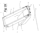
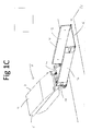
- the bridge apparatus 10 is supported by a deploying mechanism 18 of the vehicle 2 for rotating the bridge apparatus 10 about a longitudinal axis of the connecting member 14 from the storage position shown in Figure 1A through the positions shown in Figures 1B and 1C to bring the bridge apparatus 10 into contact with the ground as shown in Figure 1D .
- a locking mechanism (not shown) locks the bridge members 12 in a vertical orientation in the positions shown in Figures 1A to 1D .
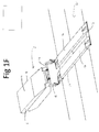
- the locking mechanism is released so that the bridge members 12 can be pivoted through the position shown in Figure 1E to the position of Figure 1F , in which the bridge members 12 lie flat on the ground and bridge a trench 20.
- the locking mechanism is then completely released from the bridge apparatus 10 so that the vehicle body 4 can be separated from the bridge elements 12 to enable vehicles to be driven across the bridge elements 12 to cross the trench 20.
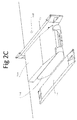
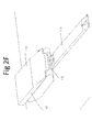
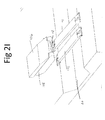
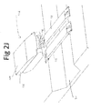
- a bridge transporting vehicle 102 of a second embodiment of the present invention has vehicle body 104 having mounting portions (not shown) on its lateral sides 106, 108 for supporting a bridge apparatus 110 comprising separate bridge elements 112, and a deploying mechanism 118 having an elongate protrusion 122 for engaging a corresponding recess 124 ( Figure 2D ) in each bridge element 112.
- the bridge elements 112 are released from the sides 106, 108 of the vehicle body 104 to rest on the ground, and the vehicle 102 transports each bridge element 112 by bringing the protrusion 122 of the deploying mechanism 118 into the recess 124 of each bridge element 112 and pivoting the deploying mechanism 118 upwards about a pivot axis 126 to lift the bridge element 112 from the ground and place the bridge element 112 in position over the trench 20.
Landscapes
- Engineering & Computer Science (AREA)
- Architecture (AREA)
- Civil Engineering (AREA)
- Structural Engineering (AREA)
- Health & Medical Sciences (AREA)
- Public Health (AREA)
- Transportation (AREA)
- Mechanical Engineering (AREA)
- Bridges Or Land Bridges (AREA)
Priority Applications (2)
| Application Number | Priority Date | Filing Date | Title |
|---|---|---|---|
| EP14171415.4A EP2952629A1 (de) | 2014-06-05 | 2014-06-05 | Fahrzeug zum Transport einer Brückenvorrichtung |
| US14/732,545 US20150354153A1 (en) | 2014-06-05 | 2015-06-05 | Vehicle for transporting elongate objects |
Applications Claiming Priority (1)
| Application Number | Priority Date | Filing Date | Title |
|---|---|---|---|
| EP14171415.4A EP2952629A1 (de) | 2014-06-05 | 2014-06-05 | Fahrzeug zum Transport einer Brückenvorrichtung |
Publications (1)
| Publication Number | Publication Date |
|---|---|
| EP2952629A1 true EP2952629A1 (de) | 2015-12-09 |
Family
ID=50976457
Family Applications (1)
| Application Number | Title | Priority Date | Filing Date |
|---|---|---|---|
| EP14171415.4A Withdrawn EP2952629A1 (de) | 2014-06-05 | 2014-06-05 | Fahrzeug zum Transport einer Brückenvorrichtung |
Country Status (2)
| Country | Link |
|---|---|
| US (1) | US20150354153A1 (de) |
| EP (1) | EP2952629A1 (de) |
Cited By (1)
| Publication number | Priority date | Publication date | Assignee | Title |
|---|---|---|---|---|
| RU2743552C1 (ru) * | 2020-07-08 | 2021-02-19 | Федеральное государственное бюджетное учреждение "Центральный научно-исследовательский испытательный институт инженерных войск имени Героя Советского Союза генерал-лейтенанта инженерных войск Д.М. Карбышева" Министерства обороны Российской Федерации | Береговая часть моста механизированного комплекса |
Families Citing this family (1)
| Publication number | Priority date | Publication date | Assignee | Title |
|---|---|---|---|---|
| CN111472257A (zh) * | 2020-04-15 | 2020-07-31 | 陕西国防工业职业技术学院 | 一种缓解高速公路堵车的装置 |
Citations (4)
| Publication number | Priority date | Publication date | Assignee | Title |
|---|---|---|---|---|
| US3305885A (en) * | 1962-10-01 | 1967-02-28 | Vaillant Jean | Bridge-laying vehicle |
| US4663793A (en) * | 1981-12-08 | 1987-05-12 | Fairey Engineering Limited | Methods of deploying a bridge of a particular construction |
| US4962556A (en) * | 1989-03-02 | 1990-10-16 | The United States Of America As Represented By The Secretary Of The Army | Lightweight, collapsible bridge module, and system with deployment and retrieval trailer |
| EP1156163A1 (de) * | 2000-05-15 | 2001-11-21 | Entreprises Morillon Corvol Courbot | Selbstschwimmende Erdbewegungsmaschine |
Family Cites Families (5)
| Publication number | Priority date | Publication date | Assignee | Title |
|---|---|---|---|---|
| DE2850849A1 (de) * | 1978-11-24 | 1980-06-04 | Porsche Ag | Vorrichtung zum zusammenlegen von spurbahnen einer bruecke zum transport auf einem fahrzeug |
| EP1585863A1 (de) * | 2003-01-22 | 2005-10-19 | Giat Industries | Verlegesystem einer brücke |
| DE102004049969B8 (de) * | 2004-10-14 | 2006-03-23 | Military Mobile Bridges Gmbh | Modulare Scherenbrücke sowie Verlegeeinrichtung und Verfahren zum Verlegen zerlegbarer Brücken |
| FR2889213B1 (fr) * | 2005-07-27 | 2007-09-07 | Mediterranee Const Ind | Systeme de transport d'une travure par un vehicule routier pouvant etre transforme en vehicule amphibie pour permettre a tout vehicule routier de franchir une breche seche ou remplie d'eau |
| GB0907749D0 (en) * | 2009-05-06 | 2009-07-22 | Pearson Eng Ltd | Bridge deploying apparatus and bridge transporting vehicle incorporating such apparatus |
-
2014
- 2014-06-05 EP EP14171415.4A patent/EP2952629A1/de not_active Withdrawn
-
2015
- 2015-06-05 US US14/732,545 patent/US20150354153A1/en not_active Abandoned
Patent Citations (4)
| Publication number | Priority date | Publication date | Assignee | Title |
|---|---|---|---|---|
| US3305885A (en) * | 1962-10-01 | 1967-02-28 | Vaillant Jean | Bridge-laying vehicle |
| US4663793A (en) * | 1981-12-08 | 1987-05-12 | Fairey Engineering Limited | Methods of deploying a bridge of a particular construction |
| US4962556A (en) * | 1989-03-02 | 1990-10-16 | The United States Of America As Represented By The Secretary Of The Army | Lightweight, collapsible bridge module, and system with deployment and retrieval trailer |
| EP1156163A1 (de) * | 2000-05-15 | 2001-11-21 | Entreprises Morillon Corvol Courbot | Selbstschwimmende Erdbewegungsmaschine |
Cited By (1)
| Publication number | Priority date | Publication date | Assignee | Title |
|---|---|---|---|---|
| RU2743552C1 (ru) * | 2020-07-08 | 2021-02-19 | Федеральное государственное бюджетное учреждение "Центральный научно-исследовательский испытательный институт инженерных войск имени Героя Советского Союза генерал-лейтенанта инженерных войск Д.М. Карбышева" Министерства обороны Российской Федерации | Береговая часть моста механизированного комплекса |
Also Published As
| Publication number | Publication date |
|---|---|
| US20150354153A1 (en) | 2015-12-10 |
Similar Documents
| Publication | Publication Date | Title |
|---|---|---|
| US20210155264A1 (en) | Integrated systems for passenger bus | |
| US8292565B1 (en) | A and R safety ramps | |
| ES2295178T3 (es) | Sistema de transporte y de carga/descarga de vagones en oblicuo en una estacion ferroviaria de transporte combinado rail/carretera y su proceso de puesta en marcha. | |
| JP6247904B2 (ja) | 鉱山用運搬車両 | |
| US9631330B2 (en) | Transportable foldable bridge | |
| CN107963026A (zh) | 货厢带有升高的自行车搁架的皮卡车 | |
| US20150354153A1 (en) | Vehicle for transporting elongate objects | |
| US12049259B2 (en) | Tailgate for vehicle | |
| US20160107620A1 (en) | Method of assisting machines at worksite | |
| US10328910B2 (en) | Collapsible chock assembly | |
| KR101696666B1 (ko) | 전술교량 | |
| JP6362918B2 (ja) | 救助工作車の展開式収納庫 | |
| US20150329160A1 (en) | Transforming trailer system and method | |
| US11208122B2 (en) | Suspension device for cables and tubings | |
| US20200269791A1 (en) | External airbag safety system | |
| US9381858B2 (en) | Laser guided docking apparatuses and methods of making and using the same | |
| JP7177600B2 (ja) | 車両運搬用の荷台 | |
| JP7220619B2 (ja) | タイヤストッパ装置、車両運搬車、タイヤストッパ | |
| US20170240227A1 (en) | Supporting system for a spare tire for a vehicle, such as truck or the like | |
| FR2841546A1 (fr) | Rehausseur avec blocage des roues pour le chargement/dechargement a quai de camions | |
| EP2427347B1 (de) | Laderampe für fahrzeuge | |
| PY2001641A (es) | Sistema de soporte y calce de vehículo de carga que se acopla a vehículo conductor | |
| FR3059654B1 (fr) | Butoir et quai comprenant un guide-butoir avec chemin d'activation et verrouillage, et methode pour le chargement/dechargement d'un vehicule a quai | |
| GB2534867A (en) | Removable platform providing an interior loadbearing false floor for managing luggage and pets in the rear space of a car | |
| JP2006512254A (ja) | 傾斜したデッキを有するトラック |
Legal Events
| Date | Code | Title | Description |
|---|---|---|---|
| PUAI | Public reference made under article 153(3) epc to a published international application that has entered the european phase |
Free format text: ORIGINAL CODE: 0009012 |
|
| AK | Designated contracting states |
Kind code of ref document: A1 Designated state(s): AL AT BE BG CH CY CZ DE DK EE ES FI FR GB GR HR HU IE IS IT LI LT LU LV MC MK MT NL NO PL PT RO RS SE SI SK SM TR |
|
| AX | Request for extension of the european patent |
Extension state: BA ME |
|
| STAA | Information on the status of an ep patent application or granted ep patent |
Free format text: STATUS: THE APPLICATION IS DEEMED TO BE WITHDRAWN |
|
| 18D | Application deemed to be withdrawn |
Effective date: 20160610 |