EP2952680B1 - Thermisch isolierter turbinenabschnitt für einen gasturbinenmotor - Google Patents
Thermisch isolierter turbinenabschnitt für einen gasturbinenmotor Download PDFInfo
- Publication number
- EP2952680B1 EP2952680B1 EP15170704.9A EP15170704A EP2952680B1 EP 2952680 B1 EP2952680 B1 EP 2952680B1 EP 15170704 A EP15170704 A EP 15170704A EP 2952680 B1 EP2952680 B1 EP 2952680B1
- Authority
- EP
- European Patent Office
- Prior art keywords
- thermally isolated
- flow path
- cooling
- plenum
- seal
- Prior art date
- Legal status (The legal status is an assumption and is not a legal conclusion. Google has not performed a legal analysis and makes no representation as to the accuracy of the status listed.)
- Active
Links
Images

Classifications
-
- F—MECHANICAL ENGINEERING; LIGHTING; HEATING; WEAPONS; BLASTING
- F01—MACHINES OR ENGINES IN GENERAL; ENGINE PLANTS IN GENERAL; STEAM ENGINES
- F01D—NON-POSITIVE DISPLACEMENT MACHINES OR ENGINES, e.g. STEAM TURBINES
- F01D5/00—Blades; Blade-carrying members; Heating, heat-insulating, cooling or antivibration means on the blades or the members
- F01D5/02—Blade-carrying members, e.g. rotors
- F01D5/08—Heating, heat-insulating or cooling means
- F01D5/085—Heating, heat-insulating or cooling means cooling fluid circulating inside the rotor
- F01D5/088—Heating, heat-insulating or cooling means cooling fluid circulating inside the rotor in a closed cavity
-
- F—MECHANICAL ENGINEERING; LIGHTING; HEATING; WEAPONS; BLASTING
- F01—MACHINES OR ENGINES IN GENERAL; ENGINE PLANTS IN GENERAL; STEAM ENGINES
- F01D—NON-POSITIVE DISPLACEMENT MACHINES OR ENGINES, e.g. STEAM TURBINES
- F01D11/00—Preventing or minimising internal leakage of working-fluid, e.g. between stages
- F01D11/001—Preventing or minimising internal leakage of working-fluid, e.g. between stages for sealing space between stator blade and rotor
-
- F—MECHANICAL ENGINEERING; LIGHTING; HEATING; WEAPONS; BLASTING
- F01—MACHINES OR ENGINES IN GENERAL; ENGINE PLANTS IN GENERAL; STEAM ENGINES
- F01D—NON-POSITIVE DISPLACEMENT MACHINES OR ENGINES, e.g. STEAM TURBINES
- F01D11/00—Preventing or minimising internal leakage of working-fluid, e.g. between stages
- F01D11/02—Preventing or minimising internal leakage of working-fluid, e.g. between stages by non-contact sealings, e.g. of labyrinth type
-
- F—MECHANICAL ENGINEERING; LIGHTING; HEATING; WEAPONS; BLASTING
- F01—MACHINES OR ENGINES IN GENERAL; ENGINE PLANTS IN GENERAL; STEAM ENGINES
- F01D—NON-POSITIVE DISPLACEMENT MACHINES OR ENGINES, e.g. STEAM TURBINES
- F01D25/00—Component parts, details, or accessories, not provided for in, or of interest apart from, other groups
- F01D25/08—Cooling; Heating; Heat-insulation
- F01D25/12—Cooling
-
- F—MECHANICAL ENGINEERING; LIGHTING; HEATING; WEAPONS; BLASTING
- F01—MACHINES OR ENGINES IN GENERAL; ENGINE PLANTS IN GENERAL; STEAM ENGINES
- F01D—NON-POSITIVE DISPLACEMENT MACHINES OR ENGINES, e.g. STEAM TURBINES
- F01D5/00—Blades; Blade-carrying members; Heating, heat-insulating, cooling or antivibration means on the blades or the members
- F01D5/02—Blade-carrying members, e.g. rotors
- F01D5/08—Heating, heat-insulating or cooling means
- F01D5/081—Cooling fluid being directed on the side of the rotor disc or at the roots of the blades
- F01D5/082—Cooling fluid being directed on the side of the rotor disc or at the roots of the blades on the side of the rotor disc
-
- F—MECHANICAL ENGINEERING; LIGHTING; HEATING; WEAPONS; BLASTING
- F01—MACHINES OR ENGINES IN GENERAL; ENGINE PLANTS IN GENERAL; STEAM ENGINES
- F01D—NON-POSITIVE DISPLACEMENT MACHINES OR ENGINES, e.g. STEAM TURBINES
- F01D5/00—Blades; Blade-carrying members; Heating, heat-insulating, cooling or antivibration means on the blades or the members
- F01D5/02—Blade-carrying members, e.g. rotors
- F01D5/08—Heating, heat-insulating or cooling means
- F01D5/081—Cooling fluid being directed on the side of the rotor disc or at the roots of the blades
- F01D5/084—Cooling fluid being directed on the side of the rotor disc or at the roots of the blades the fluid circulating at the periphery of a multistage rotor, e.g. of drum type
-
- F—MECHANICAL ENGINEERING; LIGHTING; HEATING; WEAPONS; BLASTING
- F01—MACHINES OR ENGINES IN GENERAL; ENGINE PLANTS IN GENERAL; STEAM ENGINES
- F01D—NON-POSITIVE DISPLACEMENT MACHINES OR ENGINES, e.g. STEAM TURBINES
- F01D5/00—Blades; Blade-carrying members; Heating, heat-insulating, cooling or antivibration means on the blades or the members
- F01D5/02—Blade-carrying members, e.g. rotors
- F01D5/08—Heating, heat-insulating or cooling means
- F01D5/085—Heating, heat-insulating or cooling means cooling fluid circulating inside the rotor
- F01D5/087—Heating, heat-insulating or cooling means cooling fluid circulating inside the rotor in the radial passages of the rotor disc
-
- F—MECHANICAL ENGINEERING; LIGHTING; HEATING; WEAPONS; BLASTING
- F02—COMBUSTION ENGINES; HOT-GAS OR COMBUSTION-PRODUCT ENGINE PLANTS
- F02C—GAS-TURBINE PLANTS; AIR INTAKES FOR JET-PROPULSION PLANTS; CONTROLLING FUEL SUPPLY IN AIR-BREATHING JET-PROPULSION PLANTS
- F02C3/00—Gas-turbine plants characterised by the use of combustion products as the working fluid
- F02C3/04—Gas-turbine plants characterised by the use of combustion products as the working fluid having a turbine driving a compressor
-
- F—MECHANICAL ENGINEERING; LIGHTING; HEATING; WEAPONS; BLASTING
- F02—COMBUSTION ENGINES; HOT-GAS OR COMBUSTION-PRODUCT ENGINE PLANTS
- F02C—GAS-TURBINE PLANTS; AIR INTAKES FOR JET-PROPULSION PLANTS; CONTROLLING FUEL SUPPLY IN AIR-BREATHING JET-PROPULSION PLANTS
- F02C3/00—Gas-turbine plants characterised by the use of combustion products as the working fluid
- F02C3/14—Gas-turbine plants characterised by the use of combustion products as the working fluid characterised by the arrangement of the combustion chamber in the plant
-
- F—MECHANICAL ENGINEERING; LIGHTING; HEATING; WEAPONS; BLASTING
- F02—COMBUSTION ENGINES; HOT-GAS OR COMBUSTION-PRODUCT ENGINE PLANTS
- F02C—GAS-TURBINE PLANTS; AIR INTAKES FOR JET-PROPULSION PLANTS; CONTROLLING FUEL SUPPLY IN AIR-BREATHING JET-PROPULSION PLANTS
- F02C7/00—Features, components parts, details or accessories, not provided for in, or of interest apart form groups F02C1/00 - F02C6/00; Air intakes for jet-propulsion plants
- F02C7/12—Cooling of plants
- F02C7/16—Cooling of plants characterised by cooling medium
- F02C7/18—Cooling of plants characterised by cooling medium the medium being gaseous, e.g. air
-
- F—MECHANICAL ENGINEERING; LIGHTING; HEATING; WEAPONS; BLASTING
- F01—MACHINES OR ENGINES IN GENERAL; ENGINE PLANTS IN GENERAL; STEAM ENGINES
- F01D—NON-POSITIVE DISPLACEMENT MACHINES OR ENGINES, e.g. STEAM TURBINES
- F01D11/00—Preventing or minimising internal leakage of working-fluid, e.g. between stages
-
- F—MECHANICAL ENGINEERING; LIGHTING; HEATING; WEAPONS; BLASTING
- F02—COMBUSTION ENGINES; HOT-GAS OR COMBUSTION-PRODUCT ENGINE PLANTS
- F02C—GAS-TURBINE PLANTS; AIR INTAKES FOR JET-PROPULSION PLANTS; CONTROLLING FUEL SUPPLY IN AIR-BREATHING JET-PROPULSION PLANTS
- F02C7/00—Features, components parts, details or accessories, not provided for in, or of interest apart form groups F02C1/00 - F02C6/00; Air intakes for jet-propulsion plants
- F02C7/28—Arrangement of seals
-
- F—MECHANICAL ENGINEERING; LIGHTING; HEATING; WEAPONS; BLASTING
- F05—INDEXING SCHEMES RELATING TO ENGINES OR PUMPS IN VARIOUS SUBCLASSES OF CLASSES F01-F04
- F05D—INDEXING SCHEME FOR ASPECTS RELATING TO NON-POSITIVE-DISPLACEMENT MACHINES OR ENGINES, GAS-TURBINES OR JET-PROPULSION PLANTS
- F05D2220/00—Application
- F05D2220/30—Application in turbines
- F05D2220/32—Application in turbines in gas turbines
-
- F—MECHANICAL ENGINEERING; LIGHTING; HEATING; WEAPONS; BLASTING
- F05—INDEXING SCHEMES RELATING TO ENGINES OR PUMPS IN VARIOUS SUBCLASSES OF CLASSES F01-F04
- F05D—INDEXING SCHEME FOR ASPECTS RELATING TO NON-POSITIVE-DISPLACEMENT MACHINES OR ENGINES, GAS-TURBINES OR JET-PROPULSION PLANTS
- F05D2260/00—Function
- F05D2260/20—Heat transfer, e.g. cooling
- F05D2260/231—Preventing heat transfer
-
- Y—GENERAL TAGGING OF NEW TECHNOLOGICAL DEVELOPMENTS; GENERAL TAGGING OF CROSS-SECTIONAL TECHNOLOGIES SPANNING OVER SEVERAL SECTIONS OF THE IPC; TECHNICAL SUBJECTS COVERED BY FORMER USPC CROSS-REFERENCE ART COLLECTIONS [XRACs] AND DIGESTS
- Y02—TECHNOLOGIES OR APPLICATIONS FOR MITIGATION OR ADAPTATION AGAINST CLIMATE CHANGE
- Y02T—CLIMATE CHANGE MITIGATION TECHNOLOGIES RELATED TO TRANSPORTATION
- Y02T50/00—Aeronautics or air transport
- Y02T50/60—Efficient propulsion technologies, e.g. for aircraft
Definitions
- the present disclosure relates generally to turbine cooling for a gas turbine engine, and more specifically to a thermally isolated cooling plenum in a gas turbine engine.
- Gas turbine engines such as those utilized in commercial aircraft, include a compressor section that compresses air and a combustor section that ignites combustion gasses mixed with the compressed air.
- the gasses generated by the combustion section are super-heated and expelled through a turbine section, driving the turbine section to rotate. Absent some form of cooling, the high temperatures of the expelled gasses can cause thermal degradation to occur in the turbine section.
- the turbine stages are actively cooled by passing relatively cool air through the turbine stage.
- the active cooling increases the life span of the components in the actively cooled turbine stage by reducing breakage resulting from thermal wear.
- the relatively cool air is drawn from a bleed located in the compressor section (referred to as a compressor bleed) and is piped directly to the actively cooled turbine section through a tangential on board injection (TOBI) cooling system.
- TOBI tangential on board injection
- air passing through a primary flow path of the turbine section is significantly hotter than air provided to the actively cooled region. Furthermore, in existing gas turbine engines a portion of the air in the primary flow path leaks into a cooling region radially inward of the primary flow path. As a result of the leakage, a temperature at a radially outermost edge of the cooling region is significantly hotter than a temperature at the radially innermost region resulting in a thermal gradient across the turbine stage.
- Thermal gradients such as those caused by the above described leakage, increase the stress on the components experiencing the thermal gradient and can lead to premature wear and/or breakage of the component.
- US 2010/0158668 A1 discloses a prior art gas turbine engine according to the preamble of claim 1.
- US 2011/0217158 A1 discloses a prior art cooled turbine rim seal.
- EP 0 318 026 A1 discloses a prior art warming structure of a gas turbine rotor.
- the turbine section first portion includes at least one turbine stage, wherein a portion of the at least one turbine stage extends into the thermally isolated cooling plenum through the inner diameter flow path wall, and wherein an flow path inner diameter seal is disposed in the inner diameter flow path wall adjacent at least one of the at least one turbine stages, thereby preventing fluid transfer between the primary flow path and the thermally isolated cooling plenum through the inner diameter flow path wall.
- the turbine section first portion includes at least a first stage and a second stage, and wherein the flow path inner diameter seal is positioned between the first stage and the second stage along an axis defined by the primary flow path.
- the flow path inner diameter seal is a segmented seal.
- a further exemplary embodiment of any of the above includes a fore seal disposed between the forward wall and a rotor structure, wherein the fore seal prevents fluid flow between the thermally isolated cooling plenum and an adjacent plenum.
- the fore seal is an axial non-contact seal.
- a further exemplary embodiment of any of the above includes an aft seal disposed between the aft wall and a rotor structure, wherein the aft seal prevents fluid flow into the plenum.
- At least one cooling air system is a tangential on board injection (TOBI) system.
- TOBI tangential on board injection
- An exemplary embodiment of the above includes preventing air from an adjacent plenum fore of the thermally isolated cooling plenum from entering the thermally isolated cooling plenum by at least disposing a first seal at a joint between a fore wall of the thermally isolated cooling plenum and a structure of the first rotor in the thermally isolated cooling plenum.
- the first rotor is a fore most rotor in the thermally isolated cooling plenum.
- a further exemplary embodiment of any of the above includes air from an adjacent plenum aft of the thermally isolated cooling plenum from entering the thermally isolated cooling plenum by at least disposing a second seal at a joint between an aft wall of the thermally isolated cooling plenum and a structure of the second rotor in the thermally isolated cooling plenum.
- the second rotor is an aft most rotor in the thermally isolated cooling plenum.
- a further exemplary embodiment of any of the above includes preventing air from a primary flow path from entering the thermally isolated cooling plenum by at least disposing a segmented seal in a portion of an inner diameter of the primary flow path defining the thermally isolated cooling plenum.
- a further exemplary embodiment of any of the above includes disposing the segmented seal in a portion of the inner diameter of the primary flow path further comprises disposing the segmented seal between a first high pressure turbine stage and a second high pressure turbine stage.
- distributing the cooling airflow throughout the thermally isolated cooling plenum comprises injecting the cooling airflow into the thermally isolated cooling plenum from a first source and allowing the cooling airflow to diffuse throughout the thermally isolated cooling plenum, thereby evenly distributing cooling air throughout the thermally isolated cooling plenum.
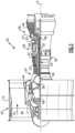
- FIG. 1 schematically illustrates a gas turbine engine 20.
- the gas turbine engine 20 is disclosed herein as a two-spool turbofan that generally incorporates a fan section 22, a compressor section 24, a combustor section 26 and a turbine section 28.
- Alternative engines might include an augmentor section (not shown) among other systems or features.
- the fan section 22 drives air along a bypass flow path B in a bypass duct defined within a nacelle 15, while the compressor section 24 drives air along a core flow path C for compression and communication into the combustor section 26 then expansion through the turbine section 28.
- the exemplary engine 20 generally includes a low speed spool 30 and a high speed spool 32 mounted for rotation about an engine central longitudinal axis A relative to an engine static structure 36 via several bearing systems 38. It should be understood that various bearing systems 38 at various locations may alternatively or additionally be provided, and the location of bearing systems 38 may be varied as appropriate to the application.
- the low speed spool 30 generally includes an inner shaft 40 that interconnects a fan 42, a first (or low) pressure compressor 44 and a first (or low) pressure turbine 46.
- the inner shaft 40 is connected to the fan 42 through a speed change mechanism, which in exemplary gas turbine engine 20 is illustrated as a geared architecture 48 to drive the fan 42 at a lower speed than the low speed spool 30.
- the high speed spool 32 includes an outer shaft 50 that interconnects a second (or high) pressure compressor 52 and a second (or high) pressure turbine 54.
- a combustor 56 is arranged in exemplary gas turbine 20 between the high pressure compressor 52 and the high pressure turbine 54.
- a mid-turbine frame 57 of the engine static structure 36 is arranged generally between the high pressure turbine 54 and the low pressure turbine 46.
- the mid-turbine frame 57 further supports bearing systems 38 in the turbine section 28.
- the inner shaft 40 and the outer shaft 50 are concentric and rotate via bearing systems 38 about the engine central longitudinal axis A which is collinear with their longitudinal axes.
- the core airflow is compressed by the low pressure compressor 44 then the high pressure compressor 52, mixed and burned with fuel in the combustor 56, then expanded over the high pressure turbine 54 and low pressure turbine 46.
- the mid-turbine frame 57 includes airfoils 59 which are in the core airflow path C.
- the turbines 46, 54 rotationally drive the respective low speed spool 30 and high speed spool 32 in response to the expansion.
- gear system 48 may be located aft of combustor section 26 or even aft of turbine section 28, and fan section 22 may be positioned forward or aft of the location of gear system 48.
- the engine 20 in one example is a high-bypass geared aircraft engine.
- the engine 20 bypass ratio is greater than about six (6), with an example embodiment being greater than about ten (10)
- the geared architecture 48 is an epicyclic gear train, such as a planetary gear system or other gear system, with a gear reduction ratio of greater than about 2.3 and the low pressure turbine 46 has a pressure ratio that is greater than about five.
- the engine 20 bypass ratio is greater than about ten (10:1)
- the fan diameter is significantly larger than that of the low pressure compressor 44
- the low pressure turbine 46 has a pressure ratio that is greater than about five (5:1).
- Low pressure turbine 46 pressure ratio is pressure measured prior to inlet of low pressure turbine 46 as related to the pressure at the outlet of the low pressure turbine 46 prior to an exhaust nozzle.
- the geared architecture 48 may be an epicycle gear train, such as a planetary gear system or other gear system, with a gear reduction ratio of greater than about 2.3:1. It should be understood, however, that the above parameters are only exemplary of one embodiment of a geared architecture engine and that the present invention is applicable to other gas turbine engines including direct drive turbofans.
- the fan section 22 of the engine 20 is designed for a particular flight condition -- typically cruise at about 0.8 Mach and about 35,000 feet (10668 m).
- "Low fan pressure ratio” is the pressure ratio across the fan blade alone, without a Fan Exit Guide Vane (“FEGV”) system.
- the low fan pressure ratio as disclosed herein according to one non-limiting embodiment is less than about 1.45.
- the "Low corrected fan tip speed” as disclosed herein according to one non-limiting embodiment is less than about 1150 ft / second (350.5 m/s).
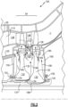
- Figure 2 schematically illustrates a sectional view 100 of a portion of the gas turbine engine 20 of Figure 1 . Illustrated in the sectional view 100 is an aft portion of the combustor 26, the high pressure turbine section 54, and a portion of the primary flow path C connecting the high pressure turbine section 54 to the low pressure turbine section 46 (illustrated in Figure 1 ) downstream of the high pressure turbine section 54.
- the combustor 26 includes a combustor exit 110 that feeds combustion gasses into the primary flow path C of the high pressure turbine section 54.
- Disposed within the high pressure turbine section 54 are two rotors 130.
- Each rotor 130 is paired with an adjacent stator 138.
- Each rotor 130/stator 138 pairing is referred to as a turbine stage.
- the high pressure turbine section 54 can include only a single stage, or more than two stages depending on the particular needs of the system.
- Each of the rotors 130 includes a root portion 132 that extends radially inward from the primary flowpath C into a thermally isolated cooling plenum 180.
- cooling air is injected onto a portion of the foremost rotor from a first cooling source, such as a tangential on board injection (TOBI) system, while cooling air is provided to the aft side of the foremost rotor from another cooling air source, such as the compressor bleed.
- a first cooling source such as a tangential on board injection (TOBI) system
- another cooling air source such as the compressor bleed.
- high pressure compressor cooling air is provided through the shaft structure and cools the aftmost side of the aftmost rotor in the high pressure turbine section. The cooling airflows from each of these sources are not isolated from other air sources within the gas turbine engine.
- the thermally isolated cooling plenum 180 is an opening positioned radially inward of the primary flowpath C, radially inward of the high pressure turbine section 54.
- the air within the opening is thermally isolated from adjacent air by walls defining the thermally isolated cooling plenum 180.
- the thermally isolated cooling plenum 180 is defined by a forward wall 150, an aft wall 160, an inner diameter of the primary flowpath C, and a shaft structure 170.
- Each of the forward wall 150 and the aft wall 160 extends radially inward from the inner diameter of the primary flowpath C, and is sealed against the root portion 132 of a corresponding rotor 130.
- the forward wall 150 is sealed against a root portion 132 of the forward rotor 130 via a seal 152 (alternately referred to as a fore seal).
- a seal 152 (alternately referred to as a fore seal).
- the aft wall 160 is sealed against a root portion 132 of the aft rotor 130 via a seal 162 (alternately referred to as an aft seal).
- the seals 152, 162 provide a barrier that prevents air from entering the thermally isolated cooling plenum 180 from the adjacent cavities that are at a higher pressure.
- the seals 152, 162 are axial non-contact seals.
- Axial non-contact seals include inner shoes and an outer carrier. The outer carrier and the shoes are generally formed from a single piece of metal and are cut such that the combined seal is formed into segments. The cuts provide a gap that allow arms associated with the seal to provide a spring force.
- One example axial non-contact seal is described and illustrated in U.S. Published Patent Application 2013/025966 . In alternate examples, any other suitable seal type can be utilized in place of the illustrated axial non-contact seals 152, 162.
- the thermally isolated cooling plenum 180 receives a cooling air feed 190 from a tangential on board injection (TOBI) system.
- the cooling air feed 190 can be provided by any gas turbine engine air system capable of providing an air feed of sufficiently high pressure to prevent backflow and sufficient temperature to cool the rotors 130. Due to the sealed nature of the thermally isolated cooling plenum 180, the only source of air entering the thermally isolated cooling plenum 180 is the cooling air feed 190.
- the cooling air feed 190 from the TOBI 120 provides a cooling air feed 190 to the entire rotor portion 132 of each of the rotors 130. Further, the isolated nature of the thermally isolated cooling plenum 180 ensures that no hot airflows contact the root portions 132 of the rotors 130. As the cooling air feed 190 enters the thermally isolated cooling plenum 180, a portion of the cooling air feed 190 enters the rotor 130 near the inner diameter of the primary flow path C, and provides an internal cooling effect to the rotor according to known rotor cooling techniques. Another portion of the cooling air feed 190 branches radially inward and flows toward a shaft structure 170. The cooling air feed 190 passes through a flow path opening 134 in a portion of the root portion 132 and passes radially inward of the rotor 130 to an aft side of the rotor 130.
- the cooling air feed 190 again splits, with a portion flowing radially outward toward the inner diameter of the primary flow path C along a flow path 194 and a portion passing through another flow path opening 134 in the root portion 132 of the second rotor 130.
- the flow path 194 flows radially outward and cools both the aft side of the first rotor 130 and the fore side of the second rotor 130.
- a further portion of the air flowing through flow path 194 enters the second rotor 130 near the inner diameter of the primary flow path C along a flow path 196, and cools the inside of the second rotor 130 in a known manner.
- a flow path 198 flows through the second flow path opening 134, passes underneath the root portion 132 of the second rotor 130, and flows radially outward toward the inner diameter of the primary flow path C.
- the flow path 198 provides cooling for the aft side of the second rotor 130.
- a seal 210 is disposed along the inner diameter of the primary flow path C between the rotors 130.
- the seal 210 prevents air in the primary flow path C from leaking into the thermally isolated cooling plenum 180, thereby minimizing the occurrences of thermal gradients across the rotors 130.
- the seal 210 is a segmented seal.
- the seal 210 can be any seal type that adequately prevents air from passing from the primary flow path C into the thermally isolated cooling plenum 180.
- FIG. 3 illustrates a flowchart 200 showing the steps of a method for cooling the stages in the high pressure compressor of Figure 3 .
- a cooling air feed 190 is provided to the thermally isolated cooling plenum 180 in a "Provide Cooling Airflow to Thermally Isolated Cooling Plenum" step 210.
- the cooling airflow is from the TOBI 120 system.
- the cooling airflow can originate from any other gas turbine engine system capable of providing an adequate volume of airflow that is cool enough to fully cool the rotors 130.
- multiple airflows originating from one or more gas turbine engine systems can be combined to form a single airflow with adequate volume and cooling capabilities. In such examples, the multiple airflows can be combined prior to entering the thermally isolated cooling plenum 180 or immediately after entering the thermally isolated cooling plenum 180.
- the cooling air feed 190 has been provided to the thermally isolated cooling plenum 180, the cooling air is distributed throughout the thermally isolated cooling plenum 180 in a "Distribute Cooling Air throughout the Thermally Isolated Cooling Plenum" step 220.
- a single source of cooling air is distributed throughout the entire thermally isolated cooling plenum, thermal gradients across the cooled rotors 130 are reduced and corresponding thermal wear is similarly reduced.
- the aft and for walls of the thermally isolated cooling plenum 180 are sealed to rotor structures to define the thermally isolated cooling plenum 180 as described above.
- the inner diameter of the primary flowpath C is sealed using a segmented seal 210, as described above. The segmented seal 210 prevents air from the primary flowpath C form leaking into the thermally isolated cooling plenum 180, thereby maintaining the thermal isolation of the cooling plenum.
- the cooling air distributed throughout the thermally isolated cooling plenum 180 enters at least one of the rotors 130 and provides an internal rotor cooling affect in a "Pass Cooling Air through Rotor Stage" step 230.
- the cooling air is then expelled into the primary flowpath C and exits the gas turbine engine 20 along the primary flowpath.
Landscapes
- Engineering & Computer Science (AREA)
- Mechanical Engineering (AREA)
- General Engineering & Computer Science (AREA)
- Chemical & Material Sciences (AREA)
- Combustion & Propulsion (AREA)
- Turbine Rotor Nozzle Sealing (AREA)
Claims (15)
- Gasturbinenmotor (20), umfassend:einen Verdichterabschnitt (24);einen Brennraum (26), der durch einen primären Strömungspfad (C) mit dem Verdichterabschnitt (24) fluidverbunden ist, wobei der primäre Strömungspfad durch eine Innendurchmesser-Strömungspfadwand und eine Außendurchmesser-Strömungspfadwand definiert ist;einen Turbinenabschnitt (28), der durch den primären Strömungspfad (C) mit dem Brennraum (26) fluidverbunden ist, wobei der Turbinenabschnitt einen ersten Abschnitt und einen zweiten Abschnitt beinhaltet, wobei der primäre Strömungspfad (C) durch den ersten Abschnitt einen hohen Druck im Verhältnis zum primären Strömungspfad durch den zweiten Abschnitt aufweist;ein thermisch isoliertes Kühlplenum (180) radial innerhalb des primären Strömungspfads (C) des ersten Abschnitts des Turbinenabschnitts (28), wobei das thermisch isolierte Kühlplenum (180) durch eine Vorderwand (150), eine Wellenstruktur (170), eine Hinterwand (160) und eine Innendurchmesserwand des primären Strömungspfads (C) definiert ist, und wobei Luft im thermisch isolierten Kühlplenum (180) thermisch von Luft im primären Strömungspfad (C) isoliert ist;einen ersten und einen zweiten Rotor (130), die in dem ersten Abschnitt des Turbinenabschnitts (28) angeordnet sind und sich durch die Innendurchmesser-Strömungspfadwand in das thermisch isolierte Kühlplenum (180) erstrecken, wobei jeder des ersten und des zweiten Rotors (130) ein internes Kühlsystem umfasst, das dazu betreibbar ist, Kühlluft vom thermisch isolierten Kühlplenum (180) zu empfangen und verbrauchte Kühlluft in den primären Strömungspfad (P) auszustoßen, und wobei jeder des ersten und des zweiten Rotors (130) eine Strömungspfadöffnung (134) in einem Abschnitt eines Fußabschnitts (132) des Rotors (130) umfasst, um einen Kühlstrom hindurchtreten zu lassen; undmindestens ein Kühlluftsystem, das dazu betreibbar ist, Kühlluft (190) aus einer einzigen Quelle an das thermisch isolierte Kühlplenum (180) bereitzustellen, derart, dass, wenn die Kühlluft (190) in das thermisch isolierte Kühlplenum (180) eintritt, ein erster Abschnitt der Kühlluft (190) in den ersten Rotor (130) nahe einem Innendurchmesser des primären Strömungspfads (C) eintritt und ein zweiter Abschnitt der Kühlluft radial nach innen abzweigt, in Richtung der Wellenstruktur (170) strömt und durch die Strömungspfadöffnung (134) des ersten Rotors (130) tritt.
- Gasturbinenmotor nach Anspruch 1,wobei der erste Abschnitt des Turbinenabschnitts mindestens eine Turbinenstufe beinhaltet; undwobei eine Strömungspfad-Innendurchmesserdichtung (210) in der Innendurchmesser-Strömungspfadwand benachbart zu mindestens einer der mindestens einen Turbinenstufen angeordnet ist, wodurch ein Fluidübertritt zwischen dem primären Strömungspfad (C) und dem thermisch isolierten Kühlplenum (180) durch die Innendurchmesser-Strömungspfadwand verhindert wird.
- Gasturbinenmotor nach Anspruch 2, wobei der erste Abschnitt des Turbinenabschnitts mindestens eine erste Stufe und eine zweite Stufe beinhaltet und wobei die Strömungspfad-Innendurchmesserdichtung (210) zwischen der ersten Stufe und der zweiten Stufe entlang einer Achse positioniert ist, die durch den primären Strömungspfad (C) definiert ist.
- Gasturbinenmotor nach Anspruch 3, wobei die Strömungspfad-Innendurchmesserdichtung (210) eine segmentierte Dichtung ist.
- Gasturbinenmotor nach einem der vorhergehenden Ansprüche, ferner umfassend eine vordere Dichtung (152), die zwischen der Vorderwand (150) und einer Rotorstruktur angeordnet ist, wobei die vordere Dichtung (152) einen Fluidstrom zwischen dem thermisch isolierten Kühlplenum (180) und einer benachbarten Plenum verhindert.
- Gasturbinenmotor nach Anspruch 5, wobei die vordere Dichtung (152) eine axiale berührungslose Dichtung ist.
- Gasturbinenmotor nach einem der vorhergehenden Ansprüche, ferner umfassend eine hintere Dichtung (162), die zwischen der Hinterwand (160) und einer Rotorstruktur angeordnet ist, wobei die hintere Dichtung einen Fluidfluss in das Plenum verhindert.
- Gasturbinenmotor nach einem der vorhergehenden Ansprüche, wobei mindestens ein Kühlluftsystem ein Tangential On Board Injection(TOBI)-System ist.
- Verfahren zum Kühlen mindestens einer Gasturbinenmotorstufe eines Gasturbinenmotors nach Anspruch 1, wobei das Verfahren Folgendes umfasst:Bereitstellen eines Kühlluftstroms an das thermisch isolierte Kühlplenum (180);Verteilen des Kühlluftstroms im gesamten thermisch isolierten Kühlplenum (180);Leiten von Kühlluft durch die mindestens eine Turbinenstufe, die sich bis in das thermisch isolierte Kühlplenum (180) erstreckt, wodurch der Kühlluftstrom aus dem thermisch isolierten Kühlplenum (180) austreten kann.
- Verfahren nach Anspruch 9, ferner umfassend Verhindern, dass Luft aus einem benachbarten Plenum vor dem thermisch isolierten Kühlplenum (180) in das thermisch isolierte Kühlplenum (180) eintritt, indem zumindest eine erste Dichtung (152) an einer Verbindungsstelle zwischen einer Vorderwand (150) des thermisch isolierten Kühlplenums (180) und einer Struktur des ersten Rotors (130) in dem thermisch isolierten Kühlplenum (180) angeordnet wird.
- Verfahren nach Anspruch 10, wobei der erste Rotor (130) ein vorderster Rotor in dem thermisch isolierten Kühlplenum (180) ist.
- Verfahren nach Anspruch 9, 10 oder 11, ferner umfassend Verhindern, das Luft aus einem benachbarten Plenum hinter dem thermisch isolierten Kühlplenum (180) in das thermisch isolierte Kühlplenum (180) eintritt, indem zumindest eine zweite Dichtung (162) an einer Verbindungsstelle zwischen einer Hinterwand (160) des thermisch isolierten Kühlplenums (180) und einer Struktur des zweiten Rotors (130) in dem thermisch isolierten Kühlplenum (180) angeordnet wird, wobei optional der zweite Rotor (130) ein hinterster Rotor in dem thermisch isolierten Kühlplenum (180) ist.
- Verfahren nach einem der Ansprüche 9 bis 12, ferner umfassend Verhindern, dass Luft aus einem primären Strömungspfad (C) in das thermisch isolierte Kühlplenum (180) eintritt, indem zumindest eine segmentierte Dichtung (210) in einem Abschnitt eines Innendurchmessers des primären Strömungspfads (C) angeordnet wird, der das thermisch isolierte Kühlplenum (180) definiert.
- Verfahren nach Anspruch 13, wobei das Anordnen der segmentierten Dichtung (210) in einem Abschnitt des Innendurchmessers des primären Strömungspfads (C) ferner Anordnen der segmentierten Dichtung (210) zwischen einer ersten Hochdruckturbinenstufe und einer zweiten Hochdruckturbinenstufe umfasst.
- Verfahren nach einem der Ansprüche 9 bis 14, wobei das Verteilen des Kühlluftstroms im gesamten thermisch isolierten Kühlplenum (180) Einspritzen des Kühlluftstroms aus einer ersten Quelle in das thermisch isolierte Kühlplenum (180) und Ermöglichen des Kühlluftstroms, sich im gesamten thermisch isolierten Kühlplenum (180) auszubreiten, umfasst, wodurch die Kühlluft gleichmäßig im gesamten thermisch isolierten Kühlplenum (180) verteilt wird.
Applications Claiming Priority (1)
| Application Number | Priority Date | Filing Date | Title |
|---|---|---|---|
| US201462008760P | 2014-06-06 | 2014-06-06 |
Publications (2)
| Publication Number | Publication Date |
|---|---|
| EP2952680A1 EP2952680A1 (de) | 2015-12-09 |
| EP2952680B1 true EP2952680B1 (de) | 2024-07-24 |
Family
ID=53284122
Family Applications (1)
| Application Number | Title | Priority Date | Filing Date |
|---|---|---|---|
| EP15170704.9A Active EP2952680B1 (de) | 2014-06-06 | 2015-06-04 | Thermisch isolierter turbinenabschnitt für einen gasturbinenmotor |
Country Status (2)
| Country | Link |
|---|---|
| US (1) | US10167723B2 (de) |
| EP (1) | EP2952680B1 (de) |
Families Citing this family (10)
| Publication number | Priority date | Publication date | Assignee | Title |
|---|---|---|---|---|
| US8641366B1 (en) * | 2013-03-07 | 2014-02-04 | United Technologies Corporation | Non-contacting seals for geared gas turbine engine bearing compartments |
| US10443443B2 (en) * | 2013-03-07 | 2019-10-15 | United Technologies Corporation | Non-contacting seals for geared gas turbine engine bearing compartments |
| US10233840B2 (en) | 2014-04-25 | 2019-03-19 | United Technologies Corporation | Compressor injector apparatus and system |
| US10634055B2 (en) * | 2015-02-05 | 2020-04-28 | United Technologies Corporation | Gas turbine engine having section with thermally isolated area |
| ES2698504T3 (es) * | 2015-07-28 | 2019-02-05 | MTU Aero Engines AG | Turbina de gas |
| US10094241B2 (en) | 2015-08-19 | 2018-10-09 | United Technologies Corporation | Non-contact seal assembly for rotational equipment |
| US10337405B2 (en) * | 2016-05-17 | 2019-07-02 | General Electric Company | Method and system for bowed rotor start mitigation using rotor cooling |
| GB201613926D0 (en) * | 2016-08-15 | 2016-09-28 | Rolls Royce Plc | Inter-stage cooling for a turbomachine |
| FR3067387B1 (fr) * | 2017-06-07 | 2019-06-28 | Safran Aircraft Engines | Ecope d'alimentation en air pour l'alimentation d'un systeme de refroidissement et de controle des jeux d'une turbine |
| EP3550106B1 (de) | 2018-04-06 | 2024-10-09 | RTX Corporation | Kühlluft für gasturbinenmotor mit thermisch isolierter kühlluftführung |
Citations (2)
| Publication number | Priority date | Publication date | Assignee | Title |
|---|---|---|---|---|
| US2988325A (en) * | 1957-07-18 | 1961-06-13 | Rolls Royce | Rotary fluid machine with means supplying fluid to rotor blade passages |
| US20040219008A1 (en) * | 2003-02-06 | 2004-11-04 | Snecma Moteurs | Ventilation device for a high pressure turbine rotor of a turbomachine |
Family Cites Families (17)
| Publication number | Priority date | Publication date | Assignee | Title |
|---|---|---|---|---|
| US3034298A (en) | 1958-06-12 | 1962-05-15 | Gen Motors Corp | Turbine cooling system |
| GB2081392B (en) * | 1980-08-06 | 1983-09-21 | Rolls Royce | Turbomachine seal |
| US4708588A (en) | 1984-12-14 | 1987-11-24 | United Technologies Corporation | Turbine cooling air supply system |
| US4815272A (en) * | 1987-05-05 | 1989-03-28 | United Technologies Corporation | Turbine cooling and thermal control |
| JP2756117B2 (ja) | 1987-11-25 | 1998-05-25 | 株式会社日立製作所 | ガスタービンロータ |
| US6183193B1 (en) | 1999-05-21 | 2001-02-06 | Pratt & Whitney Canada Corp. | Cast on-board injection nozzle with adjustable flow area |
| US6735956B2 (en) | 2001-10-26 | 2004-05-18 | Pratt & Whitney Canada Corp. | High pressure turbine blade cooling scoop |
| US6837676B2 (en) | 2002-09-11 | 2005-01-04 | Mitsubishi Heavy Industries, Ltd. | Gas turbine |
| DE10318852A1 (de) * | 2003-04-25 | 2004-11-11 | Rolls-Royce Deutschland Ltd & Co Kg | Hauptgaskanal-Innendichtung einer Hochdruckturbine |
| US20070040335A1 (en) * | 2005-08-22 | 2007-02-22 | General Electric Company | Axially adjustable sealing ring |
| US8517666B2 (en) | 2005-09-12 | 2013-08-27 | United Technologies Corporation | Turbine cooling air sealing |
| US8147178B2 (en) | 2008-12-23 | 2012-04-03 | General Electric Company | Centrifugal compressor forward thrust and turbine cooling apparatus |
| US8382432B2 (en) | 2010-03-08 | 2013-02-26 | General Electric Company | Cooled turbine rim seal |
| KR20110113881A (ko) | 2010-04-12 | 2011-10-19 | (주)엘지하우시스 | 흡차음 성능이 개선된 조립식 벽체 및 그 조립식 구조물 |
| US8920128B2 (en) | 2011-10-19 | 2014-12-30 | Honeywell International Inc. | Gas turbine engine cooling systems having hub-bleed impellers and methods for the production thereof |
| US10001061B2 (en) * | 2014-06-06 | 2018-06-19 | United Technologies Corporation | Cooling system for gas turbine engines |
| US9920652B2 (en) * | 2015-02-09 | 2018-03-20 | United Technologies Corporation | Gas turbine engine having section with thermally isolated area |
-
2015
- 2015-06-03 US US14/729,473 patent/US10167723B2/en active Active
- 2015-06-04 EP EP15170704.9A patent/EP2952680B1/de active Active
Patent Citations (2)
| Publication number | Priority date | Publication date | Assignee | Title |
|---|---|---|---|---|
| US2988325A (en) * | 1957-07-18 | 1961-06-13 | Rolls Royce | Rotary fluid machine with means supplying fluid to rotor blade passages |
| US20040219008A1 (en) * | 2003-02-06 | 2004-11-04 | Snecma Moteurs | Ventilation device for a high pressure turbine rotor of a turbomachine |
Also Published As
| Publication number | Publication date |
|---|---|
| US20150354455A1 (en) | 2015-12-10 |
| EP2952680A1 (de) | 2015-12-09 |
| US10167723B2 (en) | 2019-01-01 |
Similar Documents
| Publication | Publication Date | Title |
|---|---|---|
| EP2952680B1 (de) | Thermisch isolierter turbinenabschnitt für einen gasturbinenmotor | |
| US10072517B2 (en) | Gas turbine engine component having variable width feather seal slot | |
| US10774655B2 (en) | Gas turbine engine component with flow separating rib | |
| EP3039264B1 (de) | Gasturbinenmotordiffusorkühl- und -mischanordnung | |
| EP2944761B1 (de) | Gasturbinenmotorkomponente mit plattformkühlung | |
| EP3084136B1 (de) | Laufschaufel und zugehöriges verfahren zur kühlung einer plattform einer laufschaufel | |
| EP3126640B1 (de) | Aktive spielraumsteuerung für einen gasturbinenmotor | |
| EP3056680B1 (de) | Leckageluftsysteme für turbomaschinen | |
| EP3045681B1 (de) | Gasturbine mit hochtemperaturläufergruppe und assoziiertem kühlsystem | |
| US10364680B2 (en) | Gas turbine engine component having platform trench | |
| EP3101236B1 (de) | Dichtungen für abströmkanten von plattformen | |
| US20180080335A1 (en) | Gas turbine engine sealing arrangement | |
| EP2927429B1 (de) | Gasturbinenkomponente mit flusstrennungsrippe | |
| US10443426B2 (en) | Blade outer air seal with integrated air shield | |
| US10954796B2 (en) | Rotor bore conditioning for a gas turbine engine | |
| EP3179034B1 (de) | Turbinenkühlluft mit mehreren quellen | |
| US9957815B2 (en) | Gas powered turbine component including serpentine cooling |
Legal Events
| Date | Code | Title | Description |
|---|---|---|---|
| PUAI | Public reference made under article 153(3) epc to a published international application that has entered the european phase |
Free format text: ORIGINAL CODE: 0009012 |
|
| AK | Designated contracting states |
Kind code of ref document: A1 Designated state(s): AL AT BE BG CH CY CZ DE DK EE ES FI FR GB GR HR HU IE IS IT LI LT LU LV MC MK MT NL NO PL PT RO RS SE SI SK SM TR |
|
| AX | Request for extension of the european patent |
Extension state: BA ME |
|
| 17P | Request for examination filed |
Effective date: 20160609 |
|
| RBV | Designated contracting states (corrected) |
Designated state(s): AL AT BE BG CH CY CZ DE DK EE ES FI FR GB GR HR HU IE IS IT LI LT LU LV MC MK MT NL NO PL PT RO RS SE SI SK SM TR |
|
| RAP1 | Party data changed (applicant data changed or rights of an application transferred) |
Owner name: UNITED TECHNOLOGIES CORPORATION |
|
| STAA | Information on the status of an ep patent application or granted ep patent |
Free format text: STATUS: EXAMINATION IS IN PROGRESS |
|
| 17Q | First examination report despatched |
Effective date: 20191024 |
|
| RAP1 | Party data changed (applicant data changed or rights of an application transferred) |
Owner name: RAYTHEON TECHNOLOGIES CORPORATION |
|
| RAP3 | Party data changed (applicant data changed or rights of an application transferred) |
Owner name: RTX CORPORATION |
|
| GRAP | Despatch of communication of intention to grant a patent |
Free format text: ORIGINAL CODE: EPIDOSNIGR1 |
|
| STAA | Information on the status of an ep patent application or granted ep patent |
Free format text: STATUS: GRANT OF PATENT IS INTENDED |
|
| RIC1 | Information provided on ipc code assigned before grant |
Ipc: F02C 7/28 20060101ALN20240109BHEP Ipc: F01D 11/00 20060101ALN20240109BHEP Ipc: F02C 7/18 20060101ALI20240109BHEP Ipc: F01D 5/08 20060101AFI20240109BHEP |
|
| RIC1 | Information provided on ipc code assigned before grant |
Ipc: F02C 7/28 20060101ALN20240112BHEP Ipc: F01D 11/00 20060101ALN20240112BHEP Ipc: F02C 7/18 20060101ALI20240112BHEP Ipc: F01D 5/08 20060101AFI20240112BHEP |
|
| INTG | Intention to grant announced |
Effective date: 20240213 |
|
| GRAS | Grant fee paid |
Free format text: ORIGINAL CODE: EPIDOSNIGR3 |
|
| GRAA | (expected) grant |
Free format text: ORIGINAL CODE: 0009210 |
|
| STAA | Information on the status of an ep patent application or granted ep patent |
Free format text: STATUS: THE PATENT HAS BEEN GRANTED |
|
| AK | Designated contracting states |
Kind code of ref document: B1 Designated state(s): AL AT BE BG CH CY CZ DE DK EE ES FI FR GB GR HR HU IE IS IT LI LT LU LV MC MK MT NL NO PL PT RO RS SE SI SK SM TR |
|
| REG | Reference to a national code |
Ref country code: GB Ref legal event code: FG4D |
|
| REG | Reference to a national code |
Ref country code: CH Ref legal event code: EP |
|
| REG | Reference to a national code |
Ref country code: IE Ref legal event code: FG4D Ref country code: DE Ref legal event code: R096 Ref document number: 602015089298 Country of ref document: DE |
|
| REG | Reference to a national code |
Ref country code: LT Ref legal event code: MG9D |
|
| REG | Reference to a national code |
Ref country code: NL Ref legal event code: MP Effective date: 20240724 |
|
| PG25 | Lapsed in a contracting state [announced via postgrant information from national office to epo] |
Ref country code: PT Free format text: LAPSE BECAUSE OF FAILURE TO SUBMIT A TRANSLATION OF THE DESCRIPTION OR TO PAY THE FEE WITHIN THE PRESCRIBED TIME-LIMIT Effective date: 20241125 |
|
| REG | Reference to a national code |
Ref country code: AT Ref legal event code: MK05 Ref document number: 1706478 Country of ref document: AT Kind code of ref document: T Effective date: 20240724 |
|
| PG25 | Lapsed in a contracting state [announced via postgrant information from national office to epo] |
Ref country code: NL Free format text: LAPSE BECAUSE OF FAILURE TO SUBMIT A TRANSLATION OF THE DESCRIPTION OR TO PAY THE FEE WITHIN THE PRESCRIBED TIME-LIMIT Effective date: 20240724 |
|
| PG25 | Lapsed in a contracting state [announced via postgrant information from national office to epo] |
Ref country code: PT Free format text: LAPSE BECAUSE OF FAILURE TO SUBMIT A TRANSLATION OF THE DESCRIPTION OR TO PAY THE FEE WITHIN THE PRESCRIBED TIME-LIMIT Effective date: 20241125 Ref country code: NL Free format text: LAPSE BECAUSE OF FAILURE TO SUBMIT A TRANSLATION OF THE DESCRIPTION OR TO PAY THE FEE WITHIN THE PRESCRIBED TIME-LIMIT Effective date: 20240724 |
|
| PG25 | Lapsed in a contracting state [announced via postgrant information from national office to epo] |
Ref country code: NO Free format text: LAPSE BECAUSE OF FAILURE TO SUBMIT A TRANSLATION OF THE DESCRIPTION OR TO PAY THE FEE WITHIN THE PRESCRIBED TIME-LIMIT Effective date: 20241024 |
|
| PG25 | Lapsed in a contracting state [announced via postgrant information from national office to epo] |
Ref country code: FI Free format text: LAPSE BECAUSE OF FAILURE TO SUBMIT A TRANSLATION OF THE DESCRIPTION OR TO PAY THE FEE WITHIN THE PRESCRIBED TIME-LIMIT Effective date: 20240724 Ref country code: PL Free format text: LAPSE BECAUSE OF FAILURE TO SUBMIT A TRANSLATION OF THE DESCRIPTION OR TO PAY THE FEE WITHIN THE PRESCRIBED TIME-LIMIT Effective date: 20240724 Ref country code: GR Free format text: LAPSE BECAUSE OF FAILURE TO SUBMIT A TRANSLATION OF THE DESCRIPTION OR TO PAY THE FEE WITHIN THE PRESCRIBED TIME-LIMIT Effective date: 20241025 |
|
| PG25 | Lapsed in a contracting state [announced via postgrant information from national office to epo] |
Ref country code: BG Free format text: LAPSE BECAUSE OF FAILURE TO SUBMIT A TRANSLATION OF THE DESCRIPTION OR TO PAY THE FEE WITHIN THE PRESCRIBED TIME-LIMIT Effective date: 20240724 |
|
| PG25 | Lapsed in a contracting state [announced via postgrant information from national office to epo] |
Ref country code: LV Free format text: LAPSE BECAUSE OF FAILURE TO SUBMIT A TRANSLATION OF THE DESCRIPTION OR TO PAY THE FEE WITHIN THE PRESCRIBED TIME-LIMIT Effective date: 20240724 |
|
| PG25 | Lapsed in a contracting state [announced via postgrant information from national office to epo] |
Ref country code: AT Free format text: LAPSE BECAUSE OF FAILURE TO SUBMIT A TRANSLATION OF THE DESCRIPTION OR TO PAY THE FEE WITHIN THE PRESCRIBED TIME-LIMIT Effective date: 20240724 Ref country code: IS Free format text: LAPSE BECAUSE OF FAILURE TO SUBMIT A TRANSLATION OF THE DESCRIPTION OR TO PAY THE FEE WITHIN THE PRESCRIBED TIME-LIMIT Effective date: 20241124 |
|
| PG25 | Lapsed in a contracting state [announced via postgrant information from national office to epo] |
Ref country code: HR Free format text: LAPSE BECAUSE OF FAILURE TO SUBMIT A TRANSLATION OF THE DESCRIPTION OR TO PAY THE FEE WITHIN THE PRESCRIBED TIME-LIMIT Effective date: 20240724 |
|
| PG25 | Lapsed in a contracting state [announced via postgrant information from national office to epo] |
Ref country code: RS Free format text: LAPSE BECAUSE OF FAILURE TO SUBMIT A TRANSLATION OF THE DESCRIPTION OR TO PAY THE FEE WITHIN THE PRESCRIBED TIME-LIMIT Effective date: 20241024 Ref country code: ES Free format text: LAPSE BECAUSE OF FAILURE TO SUBMIT A TRANSLATION OF THE DESCRIPTION OR TO PAY THE FEE WITHIN THE PRESCRIBED TIME-LIMIT Effective date: 20240724 |
|
| PG25 | Lapsed in a contracting state [announced via postgrant information from national office to epo] |
Ref country code: RS Free format text: LAPSE BECAUSE OF FAILURE TO SUBMIT A TRANSLATION OF THE DESCRIPTION OR TO PAY THE FEE WITHIN THE PRESCRIBED TIME-LIMIT Effective date: 20241024 Ref country code: PL Free format text: LAPSE BECAUSE OF FAILURE TO SUBMIT A TRANSLATION OF THE DESCRIPTION OR TO PAY THE FEE WITHIN THE PRESCRIBED TIME-LIMIT Effective date: 20240724 Ref country code: NO Free format text: LAPSE BECAUSE OF FAILURE TO SUBMIT A TRANSLATION OF THE DESCRIPTION OR TO PAY THE FEE WITHIN THE PRESCRIBED TIME-LIMIT Effective date: 20241024 Ref country code: LV Free format text: LAPSE BECAUSE OF FAILURE TO SUBMIT A TRANSLATION OF THE DESCRIPTION OR TO PAY THE FEE WITHIN THE PRESCRIBED TIME-LIMIT Effective date: 20240724 Ref country code: IS Free format text: LAPSE BECAUSE OF FAILURE TO SUBMIT A TRANSLATION OF THE DESCRIPTION OR TO PAY THE FEE WITHIN THE PRESCRIBED TIME-LIMIT Effective date: 20241124 Ref country code: HR Free format text: LAPSE BECAUSE OF FAILURE TO SUBMIT A TRANSLATION OF THE DESCRIPTION OR TO PAY THE FEE WITHIN THE PRESCRIBED TIME-LIMIT Effective date: 20240724 Ref country code: GR Free format text: LAPSE BECAUSE OF FAILURE TO SUBMIT A TRANSLATION OF THE DESCRIPTION OR TO PAY THE FEE WITHIN THE PRESCRIBED TIME-LIMIT Effective date: 20241025 Ref country code: FI Free format text: LAPSE BECAUSE OF FAILURE TO SUBMIT A TRANSLATION OF THE DESCRIPTION OR TO PAY THE FEE WITHIN THE PRESCRIBED TIME-LIMIT Effective date: 20240724 Ref country code: ES Free format text: LAPSE BECAUSE OF FAILURE TO SUBMIT A TRANSLATION OF THE DESCRIPTION OR TO PAY THE FEE WITHIN THE PRESCRIBED TIME-LIMIT Effective date: 20240724 Ref country code: BG Free format text: LAPSE BECAUSE OF FAILURE TO SUBMIT A TRANSLATION OF THE DESCRIPTION OR TO PAY THE FEE WITHIN THE PRESCRIBED TIME-LIMIT Effective date: 20240724 Ref country code: AT Free format text: LAPSE BECAUSE OF FAILURE TO SUBMIT A TRANSLATION OF THE DESCRIPTION OR TO PAY THE FEE WITHIN THE PRESCRIBED TIME-LIMIT Effective date: 20240724 |
|
| PG25 | Lapsed in a contracting state [announced via postgrant information from national office to epo] |
Ref country code: RO Free format text: LAPSE BECAUSE OF FAILURE TO SUBMIT A TRANSLATION OF THE DESCRIPTION OR TO PAY THE FEE WITHIN THE PRESCRIBED TIME-LIMIT Effective date: 20240724 Ref country code: SM Free format text: LAPSE BECAUSE OF FAILURE TO SUBMIT A TRANSLATION OF THE DESCRIPTION OR TO PAY THE FEE WITHIN THE PRESCRIBED TIME-LIMIT Effective date: 20240724 Ref country code: DK Free format text: LAPSE BECAUSE OF FAILURE TO SUBMIT A TRANSLATION OF THE DESCRIPTION OR TO PAY THE FEE WITHIN THE PRESCRIBED TIME-LIMIT Effective date: 20240724 |
|
| PG25 | Lapsed in a contracting state [announced via postgrant information from national office to epo] |
Ref country code: EE Free format text: LAPSE BECAUSE OF FAILURE TO SUBMIT A TRANSLATION OF THE DESCRIPTION OR TO PAY THE FEE WITHIN THE PRESCRIBED TIME-LIMIT Effective date: 20240724 |
|
| PG25 | Lapsed in a contracting state [announced via postgrant information from national office to epo] |
Ref country code: CZ Free format text: LAPSE BECAUSE OF FAILURE TO SUBMIT A TRANSLATION OF THE DESCRIPTION OR TO PAY THE FEE WITHIN THE PRESCRIBED TIME-LIMIT Effective date: 20240724 |
|
| REG | Reference to a national code |
Ref country code: DE Ref legal event code: R097 Ref document number: 602015089298 Country of ref document: DE |
|
| PG25 | Lapsed in a contracting state [announced via postgrant information from national office to epo] |
Ref country code: IT Free format text: LAPSE BECAUSE OF FAILURE TO SUBMIT A TRANSLATION OF THE DESCRIPTION OR TO PAY THE FEE WITHIN THE PRESCRIBED TIME-LIMIT Effective date: 20240724 Ref country code: SK Free format text: LAPSE BECAUSE OF FAILURE TO SUBMIT A TRANSLATION OF THE DESCRIPTION OR TO PAY THE FEE WITHIN THE PRESCRIBED TIME-LIMIT Effective date: 20240724 |
|
| PLBE | No opposition filed within time limit |
Free format text: ORIGINAL CODE: 0009261 |
|
| STAA | Information on the status of an ep patent application or granted ep patent |
Free format text: STATUS: NO OPPOSITION FILED WITHIN TIME LIMIT |
|
| 26N | No opposition filed |
Effective date: 20250425 |
|
| PGFP | Annual fee paid to national office [announced via postgrant information from national office to epo] |
Ref country code: DE Payment date: 20250520 Year of fee payment: 11 |
|
| PGFP | Annual fee paid to national office [announced via postgrant information from national office to epo] |
Ref country code: GB Payment date: 20250520 Year of fee payment: 11 |
|
| PGFP | Annual fee paid to national office [announced via postgrant information from national office to epo] |
Ref country code: FR Payment date: 20250521 Year of fee payment: 11 |
|
| PG25 | Lapsed in a contracting state [announced via postgrant information from national office to epo] |
Ref country code: SE Free format text: LAPSE BECAUSE OF FAILURE TO SUBMIT A TRANSLATION OF THE DESCRIPTION OR TO PAY THE FEE WITHIN THE PRESCRIBED TIME-LIMIT Effective date: 20240724 |
|
| REG | Reference to a national code |
Ref country code: CH Ref legal event code: H13 Free format text: ST27 STATUS EVENT CODE: U-0-0-H10-H13 (AS PROVIDED BY THE NATIONAL OFFICE) Effective date: 20260127 |
|
| PG25 | Lapsed in a contracting state [announced via postgrant information from national office to epo] |
Ref country code: MC Free format text: LAPSE BECAUSE OF FAILURE TO SUBMIT A TRANSLATION OF THE DESCRIPTION OR TO PAY THE FEE WITHIN THE PRESCRIBED TIME-LIMIT Effective date: 20240724 |
|
| PG25 | Lapsed in a contracting state [announced via postgrant information from national office to epo] |
Ref country code: LU Free format text: LAPSE BECAUSE OF NON-PAYMENT OF DUE FEES Effective date: 20250604 |
|
| REG | Reference to a national code |
Ref country code: BE Ref legal event code: MM Effective date: 20250630 |
|
| PG25 | Lapsed in a contracting state [announced via postgrant information from national office to epo] |
Ref country code: IE Free format text: LAPSE BECAUSE OF NON-PAYMENT OF DUE FEES Effective date: 20250604 |
|
| PG25 | Lapsed in a contracting state [announced via postgrant information from national office to epo] |
Ref country code: BE Free format text: LAPSE BECAUSE OF NON-PAYMENT OF DUE FEES Effective date: 20250630 |
|
| PG25 | Lapsed in a contracting state [announced via postgrant information from national office to epo] |
Ref country code: CH Free format text: LAPSE BECAUSE OF NON-PAYMENT OF DUE FEES Effective date: 20250630 |