EP2952695B1 - Carter de soufflante - Google Patents
Carter de soufflante Download PDFInfo
- Publication number
- EP2952695B1 EP2952695B1 EP15166674.0A EP15166674A EP2952695B1 EP 2952695 B1 EP2952695 B1 EP 2952695B1 EP 15166674 A EP15166674 A EP 15166674A EP 2952695 B1 EP2952695 B1 EP 2952695B1
- Authority
- EP
- European Patent Office
- Prior art keywords
- liner segment
- liner
- head
- central axis
- fan case
- Prior art date
- Legal status (The legal status is an assumption and is not a legal conclusion. Google has not performed a legal analysis and makes no representation as to the accuracy of the status listed.)
- Not-in-force
Links
- 230000001154 acute effect Effects 0.000 claims description 42
- 239000000945 filler Substances 0.000 description 7
- 238000000034 method Methods 0.000 description 3
- 239000000853 adhesive Substances 0.000 description 2
- 230000001070 adhesive effect Effects 0.000 description 2
- 239000002131 composite material Substances 0.000 description 2
- 239000000446 fuel Substances 0.000 description 2
- 229910052751 metal Inorganic materials 0.000 description 2
- 239000002184 metal Substances 0.000 description 2
- 230000007704 transition Effects 0.000 description 2
- 239000004593 Epoxy Substances 0.000 description 1
- 229910052782 aluminium Inorganic materials 0.000 description 1
- XAGFODPZIPBFFR-UHFFFAOYSA-N aluminium Chemical compound [Al] XAGFODPZIPBFFR-UHFFFAOYSA-N 0.000 description 1
- 230000000903 blocking effect Effects 0.000 description 1
- 238000002485 combustion reaction Methods 0.000 description 1
- 230000001419 dependent effect Effects 0.000 description 1
- 239000000284 extract Substances 0.000 description 1
- 230000003116 impacting effect Effects 0.000 description 1
- 238000012423 maintenance Methods 0.000 description 1
- 230000014759 maintenance of location Effects 0.000 description 1
- 239000011159 matrix material Substances 0.000 description 1
- 238000012986 modification Methods 0.000 description 1
- 230000004048 modification Effects 0.000 description 1
- 230000001737 promoting effect Effects 0.000 description 1
- 230000001681 protective effect Effects 0.000 description 1
- 239000012783 reinforcing fiber Substances 0.000 description 1
- 230000000930 thermomechanical effect Effects 0.000 description 1
Images



Classifications
-
- F—MECHANICAL ENGINEERING; LIGHTING; HEATING; WEAPONS; BLASTING
- F01—MACHINES OR ENGINES IN GENERAL; ENGINE PLANTS IN GENERAL; STEAM ENGINES
- F01D—NON-POSITIVE DISPLACEMENT MACHINES OR ENGINES, e.g. STEAM TURBINES
- F01D25/00—Component parts, details, or accessories, not provided for in, or of interest apart from, other groups
- F01D25/24—Casings; Casing parts, e.g. diaphragms, casing fastenings
-
- F—MECHANICAL ENGINEERING; LIGHTING; HEATING; WEAPONS; BLASTING
- F01—MACHINES OR ENGINES IN GENERAL; ENGINE PLANTS IN GENERAL; STEAM ENGINES
- F01D—NON-POSITIVE DISPLACEMENT MACHINES OR ENGINES, e.g. STEAM TURBINES
- F01D21/00—Shutting-down of machines or engines, e.g. in emergency; Regulating, controlling, or safety means not otherwise provided for
- F01D21/04—Shutting-down of machines or engines, e.g. in emergency; Regulating, controlling, or safety means not otherwise provided for responsive to undesired position of rotor relative to stator or to breaking-off of a part of the rotor, e.g. indicating such position
- F01D21/045—Shutting-down of machines or engines, e.g. in emergency; Regulating, controlling, or safety means not otherwise provided for responsive to undesired position of rotor relative to stator or to breaking-off of a part of the rotor, e.g. indicating such position special arrangements in stators or in rotors dealing with breaking-off of part of rotor
-
- F—MECHANICAL ENGINEERING; LIGHTING; HEATING; WEAPONS; BLASTING
- F05—INDEXING SCHEMES RELATING TO ENGINES OR PUMPS IN VARIOUS SUBCLASSES OF CLASSES F01-F04
- F05D—INDEXING SCHEME FOR ASPECTS RELATING TO NON-POSITIVE-DISPLACEMENT MACHINES OR ENGINES, GAS-TURBINES OR JET-PROPULSION PLANTS
- F05D2220/00—Application
- F05D2220/30—Application in turbines
- F05D2220/32—Application in turbines in gas turbines
-
- F—MECHANICAL ENGINEERING; LIGHTING; HEATING; WEAPONS; BLASTING
- F05—INDEXING SCHEMES RELATING TO ENGINES OR PUMPS IN VARIOUS SUBCLASSES OF CLASSES F01-F04
- F05D—INDEXING SCHEME FOR ASPECTS RELATING TO NON-POSITIVE-DISPLACEMENT MACHINES OR ENGINES, GAS-TURBINES OR JET-PROPULSION PLANTS
- F05D2230/00—Manufacture
- F05D2230/70—Disassembly methods
-
- F—MECHANICAL ENGINEERING; LIGHTING; HEATING; WEAPONS; BLASTING
- F05—INDEXING SCHEMES RELATING TO ENGINES OR PUMPS IN VARIOUS SUBCLASSES OF CLASSES F01-F04
- F05D—INDEXING SCHEME FOR ASPECTS RELATING TO NON-POSITIVE-DISPLACEMENT MACHINES OR ENGINES, GAS-TURBINES OR JET-PROPULSION PLANTS
- F05D2240/00—Components
- F05D2240/10—Stators
- F05D2240/11—Shroud seal segments
-
- Y—GENERAL TAGGING OF NEW TECHNOLOGICAL DEVELOPMENTS; GENERAL TAGGING OF CROSS-SECTIONAL TECHNOLOGIES SPANNING OVER SEVERAL SECTIONS OF THE IPC; TECHNICAL SUBJECTS COVERED BY FORMER USPC CROSS-REFERENCE ART COLLECTIONS [XRACs] AND DIGESTS
- Y02—TECHNOLOGIES OR APPLICATIONS FOR MITIGATION OR ADAPTATION AGAINST CLIMATE CHANGE
- Y02T—CLIMATE CHANGE MITIGATION TECHNOLOGIES RELATED TO TRANSPORTATION
- Y02T50/00—Aeronautics or air transport
- Y02T50/60—Efficient propulsion technologies, e.g. for aircraft
-
- Y—GENERAL TAGGING OF NEW TECHNOLOGICAL DEVELOPMENTS; GENERAL TAGGING OF CROSS-SECTIONAL TECHNOLOGIES SPANNING OVER SEVERAL SECTIONS OF THE IPC; TECHNICAL SUBJECTS COVERED BY FORMER USPC CROSS-REFERENCE ART COLLECTIONS [XRACs] AND DIGESTS
- Y10—TECHNICAL SUBJECTS COVERED BY FORMER USPC
- Y10T—TECHNICAL SUBJECTS COVERED BY FORMER US CLASSIFICATION
- Y10T29/00—Metal working
- Y10T29/49—Method of mechanical manufacture
- Y10T29/49316—Impeller making
- Y10T29/4932—Turbomachine making
Definitions
- the present disclosure relates generally to gas turbine engines and more specifically to fan containment cases for gas turbine engines.
- Gas turbine engines used in aircraft often include a fan assembly that is driven by an engine core to push air through the engine and provide thrust for the aircraft.
- a typical fan assembly includes a fan rotor having blades and a fan case that extends around the blades of the fan rotor. During operation, the fan blades of the fan rotor are rotated to push air through the engine.
- the fan case both guides the air pushed by the fan blades and provides a protective band that blocks fan blades from being thrown out of the fan assembly in case of a blade-off event in which a fan blade is released from the fan rotor.
- Fan cases sometimes include metallic shrouds and liners positioned between the metallic shroud and the fan blades.
- Liners are generally used to achieve a desired dimensional tolerance between the fan blades and the fan case. The distance between the fan blades and the fan case may vary due to variations in dimensional tolerances or thermo-mechanical deflections. As such, liners may include an abraidable layer that the fan blades may contact without damaging the shroud. Liners may be coupled to metallic shrouds by hanger features that extend from the metallic shrouds or by adhesives that provide a permanent bond to the metallic shrouds. Over time, the liners may need to be repaired or replaced.
- Document US5336044A discloses a blade containment system and method for use in a gas turbine engine having a plurality of blades mounted on a rotatable disk.
- the system comprises an annular casing in surrounding relationship with the blades and a plurality of panels, each having an interior noise absorbing structure and an outer containment structure, disposed about an interior surface of the casing so as to position the panels outward and forward of the blades.
- the panels are supported so as to fix the panels with respect to the casing during normal engine operation and to allow an impacted one of the panels to slide circumferentially when acted upon by a predetermined blade force caused by a released portion of one of the blades impacting the panel.
- a fan case includes an annular outer shroud and a liner segment.
- the annular outer shroud is arranged to extend around a central axis of the fan case.
- the annular outer shroud has an outer surface facing away from the central axis and an inner surface facing toward the central axis.
- the liner segment is coupled to the inner surface of the annular outer shroud.
- the liner segment includes an inner radial surface, an outer radial surface spaced apart radially from the inner radial surface, and a head surface extending between and interconnecting the inner and outer radial surfaces. The head surface intersects a first ray extending from the central axis to the annular outer shroud.
- the head surface may be curved. In some embodiments, the head surface may be linear and an acute angle ⁇ may be defined between the head surface and the first ray.
- the acute angle ⁇ may be between about 10 degrees and about 30 degrees. In some embodiments, the acute angle ⁇ may be about 20 degrees.
- the head surface may include a first sub-surface and a second sub-surface.
- the first sub-surface may extend from the inner radial surface toward the outer radial surface.
- the second sub-surface may extend from the outer radial surface toward the inner radial surface and connected to the first sub-surface.
- the first sub-surface may be linear.
- An acute angle ⁇ may be defined between the first sub-surface and the first ray.
- the acute angle ⁇ may be between about 10 degrees and about 30 degrees. In some embodiments, the acute angle ⁇ may be about 20 degrees.
- the second sub-surface may be linear.
- An acute angle ⁇ may be defined between the second sub-surface and the first ray.
- the acute angle ⁇ may be between about 10 degrees and about 30 degrees. In some embodiments, the acute angle ⁇ may be different than the acute angle ⁇ .
- a fan case may include an annular shroud, a first liner segment, and a second liner segment.
- the annular outer shroud may be arranged to extend around a central axis of the fan case.
- the annular outer shroud may have an outer surface facing away from the central axis and an inner surface facing toward the central axis.
- the first liner segment may-hasve an outer radial surface and an inner radial surface.
- the outer radial surface is coupled to the inner surface of the annular outer shroud.
- the inner radial surface is radially spaced apart from the outer radial surface.
- the inner radial surface may is positioned at a first radius from the central axis.
- the first liner segment may includes a body, a head coupled to the body and extending toward a second liner segment, and a tail coupled to the body and extending away from the body.
- the second liner segment has an outer radial surface and an inner radial surface.
- the outer radial surface is coupled to the inner surface of the annular outer shroud.
- the inner radial surface is radially spaced apart from the outer radial surface.
- the inner radial surface is positioned at a first radius from the central axis.
- the second liner segment includes a body, a tail coupled to the body and extending toward the first liner segment, and a head coupled to the body and extending away from the first liner segment.
- Movement of the first liner segment in a radially outward direction causes the head of the first liner segment to engage the tail of the second liner segment.
- the second liner segment moves with the first liner segment to cause the inner surface of the first liner segment to be positioned at a second radius from the central axis and the inner surface of the second liner segment to be positioned at about the second radius from the central axis.
- the head of the first liner segment may include a head surface that intersects a first ray extending from the central axis to the annular outer shroud.
- the tail of the second liner segment may include a tail surface that intersects a second ray extending from the central axis to the annular outer shroud.
- a first acute angle ⁇ may be defined between the head surface and the first ray and the first acute angle ⁇ may be between about 10 degrees and 30 degrees. In some embodiments, the first acute angle ⁇ may be about 20 degrees.
- a second acute angle ⁇ may be defined between the tail surface and the second ray and the second acute angle ⁇ may be between about 10 degrees and 30 degrees. In some embodiments, the second acute angle ⁇ may be about 20 degrees.
- the head of the first liner segment may include a head surface that intersects a first ray extending from the central axis to the annular outer shroud.
- the tail of the second liner segment includes a tail surface that intersects the first ray.
- a method of removing a liner segment from a fan case included in a gas turbine engine mounted to an aircraft may include providing a gas turbine engine mounted to an aircraft, the gas turbine engine including a fan case arranged to extend around a central axis and including an annular outer shroud and a liner segment coupled to the annular outer shroud to lie between the annular outer shroud and the central axis, uncoupling the liner segment from the annular outer shroud, and moving the liner segment radially inward along a path toward the central axis without moving the liner segment axially relative to the central axis.
- the path may be curved.
- the gas turbine engine may further include a fan rotor extending along the central axis and a number of blades coupled to the fan rotor and extending radially outward from the central axis toward the liner segment.
- the liner segment may include a body, a head coupled to the body and including a head surface, and a tail coupled to the body and including a tail surface. The blades may rotate in a direction of travel from the tail to the head.
- An illustrative gas turbine engine 100 used in aircraft includes a fan assembly 130 driven by an engine core 120 to push air through the engine 100 and provide thrust for the aircraft as suggested in Fig. 1 .
- the illustrative fan assembly 130 includes a fan rotor 112 having a number of fan blades 114 and a fan case 10 that extends around the fan blades 114 of the fan rotor 112.
- the fan case 10 both guides the air pushed by the fan blades 114 and provides retention means for blocking the fan blades 114 from being thrown out of the fan assembly 130 in case of a blade-off event in which at least one of the fan blades 114 is released from the fan rotor 112 during operation of the gas turbine engine 100.
- the fan case 10 extends around and along a central axis 20 between a front end 22 (sometimes called the front of the fan case 10) and a back end 24 (sometimes called the back of the fan case 10) as shown in Fig. 1 .
- the fan case 10 illustratively includes an annular outer shroud 12 and a liner 14 as shown in Figs. 1 and 2 .
- the annular outer shroud 12 includes an inner surface 28 facing toward the central axis 20 and an outer surface 26 facing away from the central axis 20.
- the liner 14 is arranged along the inner surface 28 of the annular outer shroud 12 to reinforce the annular outer shroud 12.
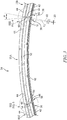
- the liner 14 is formed from a plurality of circumferentially-extending liner segments 15 that cooperate to define a full ring as shown in Figs. 1 and 3 .
- a first liner segment 15A includes an outer radial surface 44 coupled to the inner surface 28 of the annular outer shroud 12 and an inner radial surface 42 radially spaced apart from the outer radial surface 44 as shown in Fig. 3 .
- the inner radial surface 42 is spaced apart from the central axis 20 by a first radius r 1 .
- the first liner segment 15A includes a body 52, a head 54 that extends from the body 52 circumferentially toward a second segment 15B, and a tail 56 that extends circumferentially away from the second liner segment 15B from the body 52.
- the second liner segment 15B is substantially the same as the first liner segment 15A, and thus, only the first liner segment 15A will be discussed in detail.
- at least one of the blades 114 applies a force F 1 to the first liner segment 15A in a radially outward direction away from the central axis 20 as suggested in Figs. 7 and 8 .
- the force F 1 causes the first liner segment 15A to move radially outward so that the head 54 of the first liner segment 15A engages the tail 56 of the second liner segment 15B to cause the second liner segment 15B to move therewith as suggested in Figs. 7 and 8 .
- both inner surfaces 28 of the first and second liner segments 15A, 15B are moved to a second radius r 2 from the central axis 20 providing for a smooth transition between the liner segments 15A, 15B as the blade 114 moves around the central axis.
- the fan assembly 130 is illustratively mounted to the turbine engine core 120 to be driven by the engine core 120 as shown, for example, in Fig. 1 .
- the engine core 120 includes a compressor 122, a combustor 124, and a turbine 126.
- the compressor 122 is configured to compress and deliver air to the combustor 124.
- the combustor 124 is configured to mix fuel with the compressed air received from the compressor 122 and to ignite the fuel.
- the hot high pressure products of the combustion reaction in the combustor 124 are directed into the turbine 126 and the turbine 126 extracts work to drive the compressor 122 and the fan assembly 130.
- the fan case 10 includes the annular outer shroud 12 and the liner 14 as shown in Fig. 1 .
- the annular outer shroud 12 extends circumferentially around the central axis 20 of the engine 100 and extends axially between the front end 22 and the back end 24 of the fan case 10 to block a released blade from escaping the fan assembly 130.
- the liner 14 is arranged along the inner surface 28 of the annular outer shroud 12 to reinforce the annular outer shroud 12.
- the annular outer shroud 12 is illustratively an integral full ring arranged around the fan blades 114 as shown in Fig. 1 .
- the annular outer shroud 12 includes the outer surface 26 facing outward in a radial direction away from the central axis 20 and the inner surface 28 facing inward in the radial direction toward the central axis 20 as shown in Figs. 1 and 6 .
- the annular outer shroud 12 is made from metal.
- the annular outer shroud 12 is made from composite materials including a plurality of reinforcing fibers suspended in a matrix material.
- the liner 14 is formed from the plurality of circumferentially-extending liner segments 15 that cooperate to define a full ring as shown in Figs. 1 and 3 .
- Each liner segment 15 of the liner 14 is independently removable from the annular outer shroud 12 so that each liner segment 15 may be replaced without replacing one or more of the additional liner segments 15.
- the plurality of liner segments 15 are arranged around the annular outer shroud 12 to form the liner 14 as shown in Fig. 1 .
- Each liner segment 15 is spaced apart circumferentially from adjacent liner segments 15 as shown in Fig. 3 .
- the liner segments 15 are arranged to engage one another and to move therewith when a fan blade 114 is released to minimize escape of the released blade 114 from escaping fan case 10.
- a first liner segment 15A is positioned circumferentially between a second liner segment 15B and a third liner segment 15C as shown in Fig. 3 .
- the first liner segment 15A includes the inner radial surface 42, the outer radial surface 44 spaced apart from the inner radial surface 42, a head surface 46, and a tail surface 48 spaced apart from the head surface 46.
- the first liner segment 15A extends circumferentially between the head surface 46 located at a head end 36 of the first liner segment 15A and the tail surface 48 located at a tail end 38 of the first liner segment 15A.
- the inner radial surface 42 is spaced apart from the central axis 20 by a first radius r 1 as shown in Fig. 3 .
- the first liner segment 15A may move in a radially outward direction in which the first liner segment 15A is spaced apart from the central axis 20 by a second radius r 2 as shown in Fig. 8 .
- Movement of the first liner segment 15A such as movement caused by a released fan blade 114 contacting the first liner segment 15A, for example, causes the first liner segment 15A to engage the second liner segment 15B.
- the engaged first and second liners 15A, 15B move together to cause the inner radial surface 42 of the second liner segment 15B to be spaced apart from the central axis 20 by about the second radius r 2 as suggested in Figs. 7 and 8 .
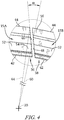
- the head surface 46 extends between and interconnects the inner and outer radial surfaces 42, 44 at the head end 36 as shown in Fig. 4 .
- the head surface 46 intersects a first ray 60 that extends from the central axis 20 toward the annular outer shroud 12.
- the head surface 46 is linear as shown in Figs. 3 and 4 .
- An acute angle ⁇ is defined between the head surface 46 and the first ray 60.
- the acute angle ⁇ is between about 10 degrees and about 30 degrees.
- the acute angle ⁇ is about 20 degrees.
- the head surface 46 is curved as shown in Fig. 9 .
- the head surface 46 includes a number of sub-surfaces as shown in Fig. 10 .
- the tail surface 48 extends between and interconnects the inner and outer radial surfaces 42, 44 at the tail end 38 as shown in Fig. 5 .
- the tail surface 48 intersects a second ray 62 that extends from the central axis 20 toward the annular outer shroud 12 as shown in Figs. 3 and 5 .
- the tail surface 48 is linear as shown in Figs. 3 and 5 .
- An acute angle ⁇ is defined between the tail surface 48 and the second ray 62. In some embodiments, the acute angle ⁇ is between about 10 degrees and about 30 degrees. In the illustrative embodiment, the acute angle ⁇ is about 20 degrees. In other embodiments, the tail surface 48 includes a number of sub-surfaces.
- the tail surface 48 is curved.
- the acute angle ⁇ and the acute angle ⁇ are the same. In other embodiments, the acute angle ⁇ and the acute angle ⁇ are different.
- the tail surface 48 of the second liner segment 15B intersects the first ray 60 that extends from the central axis 20 toward the annular outer shroud 12 as shown in Fig. 3 .
- the liner segment 15 is defined by a body 52, a head 54 coupled to the body 52 at the head end 36, and a tail 56 coupled to the body 52 at the tail end 38 as shown in Figs. 3-5 .
- the body 52 is arranged to couple the liner segment 15 to the annular outer shroud 12.
- the head 54 of the first liner segment 15A is arranged to engage the tail 56 of the second liner segment 15B to cause the second liner segment 15B to move therewith.
- the tail 56 of the first liner segment 15A is arranged to engage the head 54 of the third liner segment 15C to cause the first liner segment 15A to move therewith.
- the body 52 is coupled to and reinforces the annular outer shroud 12 as shown in Figs. 1 and 6 .
- the body 52 extends axially between the front end 22 and the back end 24 of the fan case 10 to minimize escape of a released blade from the fan assembly 130.
- the body 52 experiences a force in the outward direction such as, for example, when the body 52 is contacted by a released blade 114, the body 52 moves radially outward away from the central axis 20 relative to the second and third liner segments 15B, 15C.
- the head 54 extends away from the body 52 toward the tail 56 of the second liner segment 15B as shown in Figs. 3 and 4 .
- a third ray 64 extends from the central axis 20 of the engine 100 to the outer radial surface 44 of the first liner segment 15A as shown in Fig. 4 .
- the third ray 64 is located between the head 54 and the body 52 to define the head 54.
- the head 54 includes the head surface 46 as shown in Figs. 3 and 4 .
- the head 54 moves with the body 52 and the head surface 46 engages the tail surface 48 of the second liner segment 15B to cause the second liner segment 15B to move therewith.
- the tail 56 extends away from the body 52 toward the head 54 of the third liner segment 15C as shown in Figs. 3 and 5 .
- a fourth ray 66 extends from the central axis 20 to the outer radial surface 44 of the first liner segment 15A as shown in Fig. 5 .
- the fourth ray 66 is located between the tail 56 and the body 52 to define the tail 56.
- the tail 56 includes the tail surface 48. When a blade 114 contacts the first liner segment 15A, the tail 56 moves with the body 52.
- the first liner segment 15A is spaced apart from the second liner segment 15B as shown in Fig. 7 .
- the inner radial surfaces 42 of the first and second liner segments 15A, 15B are spaced apart from the central axis 20 by the first radius r 1 .
- at least one of the blades 114 applies a force to the first liner segment 15A in a radially outward direction away from the central axis 20.
- the force F 1 causes the first liner segment 15A to move radially outward so that the head 54 of the first liner segment 15A engages the tail 56 of the second liner segment 15B to cause the second liner segment 15B to move therewith as shown in Fig. 8 .
- the released blade 114 travels in a direction of rotation of the fan assembly 130.
- the direction of rotation is a circumferential direction from the tail end 38 to the head end 36 of the liner segments 15.
- both inner surfaces 28 of the first and second liner segments 15A, 15B are moved to the relatively greater second radius r 2 from the central axis 20 providing for a smooth transition between the liner segments 15A, 15B as the blade 114 rotates around the central axis as shown in Fig. 8 .
- the first liner segment 15A deforms into a blade-retention cavity formed between the liner segments 15 and the annular outer shroud 12 to allow a front hook 50A of the annular outer shroud 12 to block the released blade 114 from exiting the front end 22 of the fan case 10 as shown in Fig. 6 .
- the annular outer shroud 12 includes a number of liner mounts 50 that extend inward toward the central axis 20 as shown in Fig. 6 .
- Fasteners extend through the liner 14 and the liner mounts 50 to couple the liner 14 to the annular outer shroud 12.
- the liner 14 may be bonded to the annular outer shroud 12 by an adhesive or any other suitable alternatives.
- the liner mounts 50 include the front hook 50A adjacent to the front end 22 of the fan case 10, a back hook 50C adjacent to the back end 24 of the fan case 10, and an intermediate hook 50B located axially between the front and back hooks 50A, 50C as shown in Fig. 6 .
- the liner 14 is spaced apart from the inner surface 28 of the annular outer shroud between the front and intermediate hooks 50A, 50B to form the blade-retention cavity 40.
- the liner 14 is arranged to deform into the blade-retention cavity 40 when contacted by a released blade to allow the front hook 50A to minimize exiting of the released blade 114 from the front end 22 of the fan case 10.
- each liner segment 15 is formed to include a number of bolt holes for receiving fasteners to couple the liner segment 15 to the liner mounts 50 of the annular outer shroud 12 as shown in Fig. 6 .
- the bolt holes may be filled with epoxy or any other suitable filler.
- Each liner segment 15 is coupled to the hooks 50A, 50B, 50C such that the liner segment 15 may be uncoupled from the annular outer shroud 12 by moving the liner segment 15 radially inward without moving the liner segment 15 axially relative to the annular outer shroud 12 as shown in Fig. 6 .
- a liner segment 15 may be removed from the fan case 10 when the gas turbine engine 100 is mounted to an aircraft. During removal, the liner segment 15 is uncoupled from the annular outer shroud 12. The liner segment 15 is moved radially inward along a path toward the central axis 20 without moving the liner segment 15 axially relative to the central axis 20. In some embodiments, the path is curved.
- the gas turbine engine 100 further includes the fan rotor 116 extending along the central axis 20 and including the number of blades 114 coupled to the fan rotor 116. The fan blades 114 extend radially outward from the central axis 20 toward the liner segment 15. One or more of the blade 114 may be removed from the fan rotor 116 before moving the uncoupled liner segment 15.
- each liner segment 15 includes an outer tray 30, an abraidable layer 32, and a liner-filler body 34 as shown in Fig. 6 .
- the outer tray 30 couples the liner segment 15 to the annular outer shroud 12.
- the liner-filler body 34 reinforces the liner segment 15.
- the abraidable layer 32 confronts the fan blades 114 to provide an air flow path through the fan assembly 130.
- wear may occur to the abraidable layer 32 over time.
- the liner segment 15 may be replaced as part of routine or typical maintenance.
- the outer tray 30 is coupled to the liner mounts 50 to couple the liner segment 15 to the annular outer shroud 12 as shown in Fig. 6 .
- the liner segment 15 is coupled to the annular outer shroud 12 such that the blade-retention cavity 40 is formed between the outer tray 30 and the inner surface 28 of the annular outer shroud 12.
- the outer tray 30 is illustratively made of composite materials. In other embodiments, the outer tray is made from metal.
- the liner-filler body 34 is positioned radially between the outer tray 30 and the abraidable layer 32 as shown in Fig. 6 .
- the liner-filler body 34 is bonded to the outer tray 30.
- the liner-filler body 34 is a honeycomb made of aluminum.
- the abraidable layer 32 is bonded to the liner-filler body 34 as shown in Fig. 6 .
- one or more of the fan blades 114 may contact the abraidable layer 32 and cause portions of the abraidable layer 32 to separate from the liner segment 15 without harming the fan blades 114 or fan case 10 so that a dimensional tolerance between the fan blades 114 and the fan case 10 is achieved.
- FIG. 9 Another illustrative fan case 210 adapted for use in the gas turbine engine 100 is shown in Fig. 9 .
- the fan case 210 is substantially similar to the fan case 10 shown in Figs. 1-8 and described herein. Accordingly, similar reference numbers in the 200 series indicate features that are common between the fan case 10 and the fan case 210.
- the description of the fan case 10 is hereby incorporated by reference to apply to the fan case 210, except in instances when it conflicts with the specific description and drawings of the fan case 210.
- the fan case 210 includes a liner 214 formed from a number of liner segments 215 as shown in Fig. 9 .
- the head surface 246 and the tail surface 248 included in the liner segments 215 are curved.
- the head surface 246 is curved such that it intersects a ray extending from the central axis 220 toward the annular outer shroud 212.
- the tail surface 248 is curved such that it intersects a ray extending from the central axis 220 toward the annular outer shroud 212.
- the head surface 246 and the tail surface 248 have corresponding curves.
- FIG. 10 Another illustrative fan case 310 adapted for use in the gas turbine engine 100 is shown in Fig. 10 .
- the fan case 310 is substantially similar to the fan case 10 shown in Figs. 1-8 and described herein. Accordingly, similar reference numbers in the 300 series indicate features that are common between the fan case 10 and the fan case 310.
- the description of the fan case 10 is hereby incorporated by reference to apply to the fan case 310, except in instances when it conflicts with the specific description and drawings of the fan case 310.
- the fan case 310 includes a liner 314 formed from a number of liner segments 315 as shown in Fig. 10 .
- the head surface 346 includes a first sub-surface 370 extending from the inner radial surface 42 toward the outer radial surface 344 and a second sub-surface 372 extending from the outer radial surface 344 toward the inner radial surface 342 and connected to the first sub-surface 370.
- the first sub-surface 370 and the second sub-surface 372 are linear.
- a first ray 360 extends from the central axis 320 toward the outer radial surface 344 and intersects the first sub-surface 370 as shown in Fig. 10 .
- An acute angle ⁇ is defined between the first sub-surface 370 and the first ray 360.
- the acute angle ⁇ is between about 10 degrees and about 30 degrees. In the illustrative embodiment, the acute angle ⁇ is about 20 degrees.
- An acute angle ⁇ is defined between the second sub-surface 372 and the first ray 360 as shown in Fig. 10 .
- the acute angle ⁇ is between about 10 degrees and about 30 degrees. In some embodiments, the acute angle ⁇ is about 20 degrees. In the illustrative embodiment, the acute angle ⁇ is different than the acute angle ⁇ .
- the tail surface 348 includes a first sub-surface 374 extending from the inner radial surface 342 toward the outer radial surface 344 and a second sub-surface 376 extending from the outer radial surface 344 toward the inner radial surface 342 and connected to the first sub-surface 370 as shown in Fig. 10 .
- the head surface 346 and the tail surface 348 have corresponding shapes.
Landscapes
- Engineering & Computer Science (AREA)
- Mechanical Engineering (AREA)
- General Engineering & Computer Science (AREA)
- Structures Of Non-Positive Displacement Pumps (AREA)
Claims (7)
- Boîtier de ventilateur (10, 210, 310) adapté à s'étendre autour des pales (114) d'un rotor de ventilateur (112, 116) disposé dans un moteur à turbine à gaz, le boîtier de ventilateur (10, 210, 310) comprenant
une enveloppe extérieure annulaire (12) disposée de sorte qu'elle s'étend autour d'un axe central (20, 220, 320) du boîtier de ventilateur (10, 210, 310), l'enveloppe extérieure annulaire (12) ayant une surface extérieure (26) orientée dans la direction opposée de l'axe central (20, 220, 320) et une surface intérieure (28) orientée vers l'axe central (20, 220, 320) et
un segment de doublure (15, 215, 315) couplé à la surface intérieure (28) de l'enveloppe extérieure annulaire (12), le segment de doublure (15, 215, 315) comprenant une surface intérieure radiale (42, 242, 342), une surface extérieure radiale (44, 244, 344) espacée radialement de la surface intérieure radiale (42, 242, 342) et une surface de tête (46, 246, 346), qui s'étend entre et relie entre elles les surfaces intérieure et extérieure radiales (42, 342, 44, 344), la surface de tête (46, 246, 346) croisant un premier rayon (60, 360) qui s'étend à partir de l'axe central (20, 220, 320) jusqu'à l'enveloppe extérieure annulaire (12),
un premier segment de doublure (15A, 215A, 315A), dont la surface extérieure radiale (44, 244, 344) est couplée à la surface intérieure (28) de l'enveloppe extérieure annulaire (12) et dont la surface intérieure radiale (42, 242, 342) est radialement espacée de la surface extérieure radiale (44, 244, 344), la surface intérieure radiale (42, 242, 342) étant positionnée sur un premier rayon de l'axe central (20, 220, 320), le premier segment de doublure (15A, 215A, 315A) comprenant un corps, une tête couplée au corps et s'étendant à partir du corps de manière circonférentielle vers un deuxième segment de doublure (15B) et une partie arrière couplée au corps et s'étendant de manière circonférentielle dans la direction opposée du corps, et
un deuxième segment de doublure (15B), dont la surface extérieure radiale (44, 244, 344) est couplée à la surface intérieure (28) de l'enveloppe extérieure annulaire (12) et dont la surface intérieure radiale (42, 242, 342) est radialement espacée de la surface extérieure radiale (44, 244, 344), la surface intérieure radiale (42, 242, 342) étant positionnée sur un premier rayon de l'axe central (20, 220, 320), le deuxième segment de doublure (15B) comprenant un corps, une partie arrière (56) couplée au corps et s'étendant de manière circonférentielle dans la direction opposée du corps vers le premier segment de doublure (15A, 215A, 315A) et une tête couplée au corps et s'étendant de manière circonférentielle dans la direction opposée du corps et du premier segment de doublure (15A, 215A, 315A),
le boîtier de ventilateur (10, 210, 310) étant configuré de sorte qu'un déplacement du premier segment de doublure (15A, 215A, 315A) dans une direction radiale vers l'extérieur provoque que la tête (54) du premier segment de doublure (15A, 215A, 315A) vient en prise avec la partie arrière (56) du deuxième segment de doublure (15B) et se déplace avec celui-ci pour provoquer que la surface intérieure (28) du premier segment de doublure (15A, 215A, 315A) est positionnée sur un deuxième rayon (r2) de l'axe central (20, 220, 320) et la surface intérieure (28) du deuxième segment de doublure (15B) est positionnée environ sur le deuxième rayon (r2) de l'axe central (20, 220, 320),
la tête (54) du premier segment de doublure (15A, 215A, 315A) comprenant la surface de tête (46, 246, 346), qui croise le premier rayon (60, 360), qui s'étend à partir de l'axe central (20, 220, 320) jusqu'à l'enveloppe extérieure annulaire (12) et la partie arrière (56) du deuxième segment de doublure (15B) comprenant une surface arrière (48), qui croise le premier rayon (60, 360). - Boîtier de ventilateur (10, 210, 310) selon la revendication 1, dans lequel la surface de tête (246) est courbée.
- Boîtier de ventilateur (10, 210, 310) selon la revendication 1, dans lequel la surface de tête (46) est linéaire et un angle aigu α est défini entre la surface de tête (46) et le premier rayon (60) et l'angle aigu α est compris entre environ 10 degrés et environ 30 degrés, de préférence environ 20 degrés.
- Boîtier de ventilateur (10, 210, 310) selon la revendication 1, dans lequel la surface de tête (346) comprend une première sous-surface (370), qui s'étend à partir de la surface intérieure radiale (342) vers la surface extérieure radiale (344) et une deuxième sous-surface (372), qui s'étend à partir de la surface extérieure radiale (344) vers la surface intérieure radiale (342) et qui est reliée à la première sous-surface (370).
- Boîtier de ventilateur (10, 210, 310) selon la revendication 4, dans lequel la première sous-surface (370) est linéaire et un angle aigu α est défini entre la première sous-surface (370) et le premier rayon (360) et l'angle aigu α est compris entre environ 10 degrés et environ 30 degrés, de préférence environ 20 degrés.
- Boîtier de ventilateur (10, 210, 310) selon la revendication 4 ou la revendication 5, dans lequel la deuxième sous-surface (372) est linéaire et un angle aigu β est défini entre la deuxième sous-surface (372) et le premier rayon (360) et l'angle aigu β est compris entre environ 10 degrés et environ 30 degrés.
- Boîtier de ventilateur (10, 210, 310) selon la revendication 6, dans lequel l'angle aigu β est différent de l'angle aigu α.
Applications Claiming Priority (1)
| Application Number | Priority Date | Filing Date | Title |
|---|---|---|---|
| US201462008131P | 2014-06-05 | 2014-06-05 |
Publications (2)
| Publication Number | Publication Date |
|---|---|
| EP2952695A1 EP2952695A1 (fr) | 2015-12-09 |
| EP2952695B1 true EP2952695B1 (fr) | 2018-07-25 |
Family
ID=53188864
Family Applications (1)
| Application Number | Title | Priority Date | Filing Date |
|---|---|---|---|
| EP15166674.0A Not-in-force EP2952695B1 (fr) | 2014-06-05 | 2015-05-07 | Carter de soufflante |
Country Status (2)
| Country | Link |
|---|---|
| US (1) | US10180082B2 (fr) |
| EP (1) | EP2952695B1 (fr) |
Families Citing this family (13)
| Publication number | Priority date | Publication date | Assignee | Title |
|---|---|---|---|---|
| EP2905430A1 (fr) * | 2014-02-11 | 2015-08-12 | Siemens Aktiengesellschaft | Dispositif de manipulation |
| ITUB20155479A1 (it) | 2015-11-11 | 2017-05-11 | Lonati Spa | Procedimento per la preparazione di un manufatto tubolare del tipo calza o simile al prelievo automatizzato al termine della sua formazione su una macchina circolare a doppio cilindro con almeno una alimentazione o caduta e macchina circolare a doppio cilindro per la sua esecuzione. |
| US10907651B2 (en) * | 2016-01-12 | 2021-02-02 | Rolls-Royce Corporation | Fan track liner subassembly angled upturn joint |
| US10260522B2 (en) * | 2016-05-19 | 2019-04-16 | Rolls-Royce Corporation | Liner system |
| US10533450B2 (en) | 2017-10-30 | 2020-01-14 | United Technologies Corporation | Ballistic liner install methods |
| GB201816989D0 (en) * | 2018-10-18 | 2018-12-05 | Rolls Royce Plc | Debris retention |
| GB201816992D0 (en) * | 2018-10-18 | 2018-12-05 | Rolls Royce Plc | Debris retention |
| GB201816990D0 (en) * | 2018-10-18 | 2018-12-05 | Rolls Royce Plc | Debris retention |
| GB201903716D0 (en) * | 2019-03-19 | 2019-05-01 | Rolls Royce Plc | Acoustic liner panel and containment for a gas turbine engine |
| US11162425B2 (en) * | 2019-06-11 | 2021-11-02 | Rolls-Royce Corporation | Assembly fixture |
| US11319833B2 (en) * | 2020-04-24 | 2022-05-03 | General Electric Company | Fan case with crack-arresting backsheet structure and removable containment cartridge |
| US11732612B2 (en) * | 2021-12-22 | 2023-08-22 | Rolls-Royce North American Technologies Inc. | Turbine engine fan track liner with tip injection air recirculation passage |
| US12084977B1 (en) * | 2023-10-10 | 2024-09-10 | Rolls-Royce North American Technologies Inc. | Gas turbine engine with fan track liner having triply periodic minimal surface reinforcement |
Family Cites Families (17)
| Publication number | Priority date | Publication date | Assignee | Title |
|---|---|---|---|---|
| US3970318A (en) * | 1975-09-26 | 1976-07-20 | General Electric Company | Sealing means for a segmented ring |
| US5336044A (en) * | 1993-08-06 | 1994-08-09 | General Electric Company | Blade containment system and method |
| US5486086A (en) | 1994-01-04 | 1996-01-23 | General Electric Company | Blade containment system |
| DE59710924D1 (de) * | 1997-09-15 | 2003-12-04 | Alstom Switzerland Ltd | Kühlvorrichtung für Gasturbinenkomponenten |
| JP3999395B2 (ja) * | 1999-03-03 | 2007-10-31 | 三菱重工業株式会社 | ガスタービン分割環 |
| US6217277B1 (en) | 1999-10-05 | 2001-04-17 | Pratt & Whitney Canada Corp. | Turbofan engine including improved fan blade lining |
| US6364603B1 (en) | 1999-11-01 | 2002-04-02 | Robert P. Czachor | Fan case for turbofan engine having a fan decoupler |
| GB2356022B (en) | 1999-11-02 | 2003-12-10 | Rolls Royce Plc | Gas turbine engines |
| US20050067788A1 (en) * | 2003-09-25 | 2005-03-31 | Siemens Westinghouse Power Corporation | Outer air seal assembly |
| US7721525B2 (en) | 2006-07-19 | 2010-05-25 | Rohr, Inc. | Aircraft engine inlet having zone of deformation |
| US8016543B2 (en) | 2007-04-02 | 2011-09-13 | Michael Scott Braley | Composite case armor for jet engine fan case containment |
| FR2926791B1 (fr) | 2008-01-29 | 2010-05-28 | Aircelle Sa | Entree d'air pour nacelle d'aeronef, et ensemble propulsif comprenant une telle entree d'air |
| US8333558B2 (en) | 2008-03-05 | 2012-12-18 | General Electric Company | Containment cases and method of manufacture |
| US8202041B2 (en) | 2008-10-31 | 2012-06-19 | Pratt & Whitney Canada Corp | Fan case for turbofan engine |
| US8197191B2 (en) | 2009-04-14 | 2012-06-12 | Rohr, Inc. | Inlet section of an aircraft engine nacelle |
| US9017018B2 (en) | 2009-09-24 | 2015-04-28 | Rolls-Royce Corporation | Annular seal |
| US20120082541A1 (en) | 2010-09-30 | 2012-04-05 | Enzo Macchia | Gas turbine engine casing |
-
2015
- 2015-04-30 US US14/701,124 patent/US10180082B2/en active Active
- 2015-05-07 EP EP15166674.0A patent/EP2952695B1/fr not_active Not-in-force
Non-Patent Citations (1)
| Title |
|---|
| None * |
Also Published As
| Publication number | Publication date |
|---|---|
| US20150354408A1 (en) | 2015-12-10 |
| US10180082B2 (en) | 2019-01-15 |
| EP2952695A1 (fr) | 2015-12-09 |
Similar Documents
| Publication | Publication Date | Title |
|---|---|---|
| US10180082B2 (en) | Fan case | |
| US10731507B2 (en) | Fan case assemblies | |
| EP2940283B1 (fr) | Ensemble de coffrage de soufflante de turbomachine | |
| US9085992B2 (en) | Turbomachine casing assembly | |
| US11008887B2 (en) | Fan containment assembly having a nesting cavity | |
| US10024191B2 (en) | Fan track liner designed to yield next to fan case hook | |
| EP2927432B1 (fr) | Moteur à turbine à gaz, procede de fabrication d'un moteur à turbine à gaz et carter de soufflante | |
| EP2902592B1 (fr) | Moteur à turbine à gaz | |
| EP2952696B1 (fr) | Ensemble turboréacteur à double flux avec cartouche de revêtement pour le carter de soufflante | |
| KR101828637B1 (ko) | 터빈 케이싱 상에 쉴드를 장착하기 위한 방법 및 이를 수행하기 위한 장착 조립체 | |
| EP3351746B1 (fr) | Carter moteur pour pale de ventilateur hors de rétention | |
| EP2597270B1 (fr) | Ensemble carter de turbomachine | |
| US9835046B2 (en) | Gas turbine engine | |
| US10337350B2 (en) | Gas turbine engine | |
| EP3020927A1 (fr) | Roue de turbine avec aube en céramique | |
| EP2902593B1 (fr) | Système de confinement de soufflante dans un moteur à turbine à gaz axial | |
| US20140064938A1 (en) | Rub tolerant fan case | |
| EP3001040B1 (fr) | Moteur a turbine a gaz | |
| EP0927815A2 (fr) | Revêtement d'une virole d'une soufflante | |
| US20210054762A1 (en) | Gas turbine engine fan bumper | |
| US12084977B1 (en) | Gas turbine engine with fan track liner having triply periodic minimal surface reinforcement | |
| EP4644665A1 (fr) | Anneau de rétention pour moteur à turbine à gaz | |
| EP4717877A1 (fr) | Disque aubagé pour un rotor entraîné d'un moteur d'un groupe de propulsion d'aéronef, groupe de propulsion pour un aéronef et aéronef |
Legal Events
| Date | Code | Title | Description |
|---|---|---|---|
| PUAI | Public reference made under article 153(3) epc to a published international application that has entered the european phase |
Free format text: ORIGINAL CODE: 0009012 |
|
| AK | Designated contracting states |
Kind code of ref document: A1 Designated state(s): AL AT BE BG CH CY CZ DE DK EE ES FI FR GB GR HR HU IE IS IT LI LT LU LV MC MK MT NL NO PL PT RO RS SE SI SK SM TR |
|
| AX | Request for extension of the european patent |
Extension state: BA ME |
|
| 17P | Request for examination filed |
Effective date: 20160607 |
|
| RBV | Designated contracting states (corrected) |
Designated state(s): AL AT BE BG CH CY CZ DE DK EE ES FI FR GB GR HR HU IE IS IT LI LT LU LV MC MK MT NL NO PL PT RO RS SE SI SK SM TR |
|
| STAA | Information on the status of an ep patent application or granted ep patent |
Free format text: STATUS: EXAMINATION IS IN PROGRESS |
|
| 17Q | First examination report despatched |
Effective date: 20170614 |
|
| RIC1 | Information provided on ipc code assigned before grant |
Ipc: F01D 21/04 20060101AFI20180208BHEP Ipc: F01D 25/24 20060101ALI20180208BHEP |
|
| GRAP | Despatch of communication of intention to grant a patent |
Free format text: ORIGINAL CODE: EPIDOSNIGR1 |
|
| STAA | Information on the status of an ep patent application or granted ep patent |
Free format text: STATUS: GRANT OF PATENT IS INTENDED |
|
| INTG | Intention to grant announced |
Effective date: 20180417 |
|
| GRAS | Grant fee paid |
Free format text: ORIGINAL CODE: EPIDOSNIGR3 |
|
| GRAA | (expected) grant |
Free format text: ORIGINAL CODE: 0009210 |
|
| STAA | Information on the status of an ep patent application or granted ep patent |
Free format text: STATUS: THE PATENT HAS BEEN GRANTED |
|
| AK | Designated contracting states |
Kind code of ref document: B1 Designated state(s): AL AT BE BG CH CY CZ DE DK EE ES FI FR GB GR HR HU IE IS IT LI LT LU LV MC MK MT NL NO PL PT RO RS SE SI SK SM TR |
|
| REG | Reference to a national code |
Ref country code: GB Ref legal event code: FG4D |
|
| REG | Reference to a national code |
Ref country code: CH Ref legal event code: EP |
|
| REG | Reference to a national code |
Ref country code: AT Ref legal event code: REF Ref document number: 1021993 Country of ref document: AT Kind code of ref document: T Effective date: 20180815 |
|
| REG | Reference to a national code |
Ref country code: IE Ref legal event code: FG4D |
|
| REG | Reference to a national code |
Ref country code: DE Ref legal event code: R096 Ref document number: 602015013877 Country of ref document: DE |
|
| REG | Reference to a national code |
Ref country code: NL Ref legal event code: MP Effective date: 20180725 |
|
| REG | Reference to a national code |
Ref country code: LT Ref legal event code: MG4D |
|
| PG25 | Lapsed in a contracting state [announced via postgrant information from national office to epo] |
Ref country code: NL Free format text: LAPSE BECAUSE OF FAILURE TO SUBMIT A TRANSLATION OF THE DESCRIPTION OR TO PAY THE FEE WITHIN THE PRESCRIBED TIME-LIMIT Effective date: 20180725 |
|
| REG | Reference to a national code |
Ref country code: AT Ref legal event code: MK05 Ref document number: 1021993 Country of ref document: AT Kind code of ref document: T Effective date: 20180725 |
|
| PG25 | Lapsed in a contracting state [announced via postgrant information from national office to epo] |
Ref country code: IS Free format text: LAPSE BECAUSE OF FAILURE TO SUBMIT A TRANSLATION OF THE DESCRIPTION OR TO PAY THE FEE WITHIN THE PRESCRIBED TIME-LIMIT Effective date: 20181125 Ref country code: RS Free format text: LAPSE BECAUSE OF FAILURE TO SUBMIT A TRANSLATION OF THE DESCRIPTION OR TO PAY THE FEE WITHIN THE PRESCRIBED TIME-LIMIT Effective date: 20180725 Ref country code: AT Free format text: LAPSE BECAUSE OF FAILURE TO SUBMIT A TRANSLATION OF THE DESCRIPTION OR TO PAY THE FEE WITHIN THE PRESCRIBED TIME-LIMIT Effective date: 20180725 Ref country code: LT Free format text: LAPSE BECAUSE OF FAILURE TO SUBMIT A TRANSLATION OF THE DESCRIPTION OR TO PAY THE FEE WITHIN THE PRESCRIBED TIME-LIMIT Effective date: 20180725 Ref country code: SE Free format text: LAPSE BECAUSE OF FAILURE TO SUBMIT A TRANSLATION OF THE DESCRIPTION OR TO PAY THE FEE WITHIN THE PRESCRIBED TIME-LIMIT Effective date: 20180725 Ref country code: BG Free format text: LAPSE BECAUSE OF FAILURE TO SUBMIT A TRANSLATION OF THE DESCRIPTION OR TO PAY THE FEE WITHIN THE PRESCRIBED TIME-LIMIT Effective date: 20181025 Ref country code: FI Free format text: LAPSE BECAUSE OF FAILURE TO SUBMIT A TRANSLATION OF THE DESCRIPTION OR TO PAY THE FEE WITHIN THE PRESCRIBED TIME-LIMIT Effective date: 20180725 Ref country code: GR Free format text: LAPSE BECAUSE OF FAILURE TO SUBMIT A TRANSLATION OF THE DESCRIPTION OR TO PAY THE FEE WITHIN THE PRESCRIBED TIME-LIMIT Effective date: 20181026 Ref country code: NO Free format text: LAPSE BECAUSE OF FAILURE TO SUBMIT A TRANSLATION OF THE DESCRIPTION OR TO PAY THE FEE WITHIN THE PRESCRIBED TIME-LIMIT Effective date: 20181025 Ref country code: PL Free format text: LAPSE BECAUSE OF FAILURE TO SUBMIT A TRANSLATION OF THE DESCRIPTION OR TO PAY THE FEE WITHIN THE PRESCRIBED TIME-LIMIT Effective date: 20180725 |
|
| PG25 | Lapsed in a contracting state [announced via postgrant information from national office to epo] |
Ref country code: LV Free format text: LAPSE BECAUSE OF FAILURE TO SUBMIT A TRANSLATION OF THE DESCRIPTION OR TO PAY THE FEE WITHIN THE PRESCRIBED TIME-LIMIT Effective date: 20180725 Ref country code: HR Free format text: LAPSE BECAUSE OF FAILURE TO SUBMIT A TRANSLATION OF THE DESCRIPTION OR TO PAY THE FEE WITHIN THE PRESCRIBED TIME-LIMIT Effective date: 20180725 Ref country code: AL Free format text: LAPSE BECAUSE OF FAILURE TO SUBMIT A TRANSLATION OF THE DESCRIPTION OR TO PAY THE FEE WITHIN THE PRESCRIBED TIME-LIMIT Effective date: 20180725 |
|
| REG | Reference to a national code |
Ref country code: DE Ref legal event code: R097 Ref document number: 602015013877 Country of ref document: DE |
|
| PG25 | Lapsed in a contracting state [announced via postgrant information from national office to epo] |
Ref country code: IT Free format text: LAPSE BECAUSE OF FAILURE TO SUBMIT A TRANSLATION OF THE DESCRIPTION OR TO PAY THE FEE WITHIN THE PRESCRIBED TIME-LIMIT Effective date: 20180725 Ref country code: RO Free format text: LAPSE BECAUSE OF FAILURE TO SUBMIT A TRANSLATION OF THE DESCRIPTION OR TO PAY THE FEE WITHIN THE PRESCRIBED TIME-LIMIT Effective date: 20180725 Ref country code: CZ Free format text: LAPSE BECAUSE OF FAILURE TO SUBMIT A TRANSLATION OF THE DESCRIPTION OR TO PAY THE FEE WITHIN THE PRESCRIBED TIME-LIMIT Effective date: 20180725 Ref country code: ES Free format text: LAPSE BECAUSE OF FAILURE TO SUBMIT A TRANSLATION OF THE DESCRIPTION OR TO PAY THE FEE WITHIN THE PRESCRIBED TIME-LIMIT Effective date: 20180725 Ref country code: EE Free format text: LAPSE BECAUSE OF FAILURE TO SUBMIT A TRANSLATION OF THE DESCRIPTION OR TO PAY THE FEE WITHIN THE PRESCRIBED TIME-LIMIT Effective date: 20180725 |
|
| PG25 | Lapsed in a contracting state [announced via postgrant information from national office to epo] |
Ref country code: DK Free format text: LAPSE BECAUSE OF FAILURE TO SUBMIT A TRANSLATION OF THE DESCRIPTION OR TO PAY THE FEE WITHIN THE PRESCRIBED TIME-LIMIT Effective date: 20180725 Ref country code: SM Free format text: LAPSE BECAUSE OF FAILURE TO SUBMIT A TRANSLATION OF THE DESCRIPTION OR TO PAY THE FEE WITHIN THE PRESCRIBED TIME-LIMIT Effective date: 20180725 Ref country code: SK Free format text: LAPSE BECAUSE OF FAILURE TO SUBMIT A TRANSLATION OF THE DESCRIPTION OR TO PAY THE FEE WITHIN THE PRESCRIBED TIME-LIMIT Effective date: 20180725 |
|
| PLBE | No opposition filed within time limit |
Free format text: ORIGINAL CODE: 0009261 |
|
| STAA | Information on the status of an ep patent application or granted ep patent |
Free format text: STATUS: NO OPPOSITION FILED WITHIN TIME LIMIT |
|
| 26N | No opposition filed |
Effective date: 20190426 |
|
| PG25 | Lapsed in a contracting state [announced via postgrant information from national office to epo] |
Ref country code: SI Free format text: LAPSE BECAUSE OF FAILURE TO SUBMIT A TRANSLATION OF THE DESCRIPTION OR TO PAY THE FEE WITHIN THE PRESCRIBED TIME-LIMIT Effective date: 20180725 |
|
| PGFP | Annual fee paid to national office [announced via postgrant information from national office to epo] |
Ref country code: FR Payment date: 20190527 Year of fee payment: 5 |
|
| REG | Reference to a national code |
Ref country code: DE Ref legal event code: R119 Ref document number: 602015013877 Country of ref document: DE |
|
| REG | Reference to a national code |
Ref country code: CH Ref legal event code: PL |
|
| GBPC | Gb: european patent ceased through non-payment of renewal fee |
Effective date: 20190507 |
|
| PG25 | Lapsed in a contracting state [announced via postgrant information from national office to epo] |
Ref country code: CH Free format text: LAPSE BECAUSE OF NON-PAYMENT OF DUE FEES Effective date: 20190531 Ref country code: LI Free format text: LAPSE BECAUSE OF NON-PAYMENT OF DUE FEES Effective date: 20190531 Ref country code: MC Free format text: LAPSE BECAUSE OF FAILURE TO SUBMIT A TRANSLATION OF THE DESCRIPTION OR TO PAY THE FEE WITHIN THE PRESCRIBED TIME-LIMIT Effective date: 20180725 |
|
| REG | Reference to a national code |
Ref country code: BE Ref legal event code: MM Effective date: 20190531 |
|
| PG25 | Lapsed in a contracting state [announced via postgrant information from national office to epo] |
Ref country code: LU Free format text: LAPSE BECAUSE OF NON-PAYMENT OF DUE FEES Effective date: 20190507 |
|
| PG25 | Lapsed in a contracting state [announced via postgrant information from national office to epo] |
Ref country code: TR Free format text: LAPSE BECAUSE OF FAILURE TO SUBMIT A TRANSLATION OF THE DESCRIPTION OR TO PAY THE FEE WITHIN THE PRESCRIBED TIME-LIMIT Effective date: 20180725 |
|
| PG25 | Lapsed in a contracting state [announced via postgrant information from national office to epo] |
Ref country code: DE Free format text: LAPSE BECAUSE OF NON-PAYMENT OF DUE FEES Effective date: 20191203 Ref country code: GB Free format text: LAPSE BECAUSE OF NON-PAYMENT OF DUE FEES Effective date: 20190507 Ref country code: IE Free format text: LAPSE BECAUSE OF NON-PAYMENT OF DUE FEES Effective date: 20190507 |
|
| PG25 | Lapsed in a contracting state [announced via postgrant information from national office to epo] |
Ref country code: BE Free format text: LAPSE BECAUSE OF NON-PAYMENT OF DUE FEES Effective date: 20190531 |
|
| PG25 | Lapsed in a contracting state [announced via postgrant information from national office to epo] |
Ref country code: PT Free format text: LAPSE BECAUSE OF FAILURE TO SUBMIT A TRANSLATION OF THE DESCRIPTION OR TO PAY THE FEE WITHIN THE PRESCRIBED TIME-LIMIT Effective date: 20181125 |
|
| PG25 | Lapsed in a contracting state [announced via postgrant information from national office to epo] |
Ref country code: FR Free format text: LAPSE BECAUSE OF NON-PAYMENT OF DUE FEES Effective date: 20200531 |
|
| PG25 | Lapsed in a contracting state [announced via postgrant information from national office to epo] |
Ref country code: CY Free format text: LAPSE BECAUSE OF FAILURE TO SUBMIT A TRANSLATION OF THE DESCRIPTION OR TO PAY THE FEE WITHIN THE PRESCRIBED TIME-LIMIT Effective date: 20180725 |
|
| PG25 | Lapsed in a contracting state [announced via postgrant information from national office to epo] |
Ref country code: MT Free format text: LAPSE BECAUSE OF FAILURE TO SUBMIT A TRANSLATION OF THE DESCRIPTION OR TO PAY THE FEE WITHIN THE PRESCRIBED TIME-LIMIT Effective date: 20180725 Ref country code: HU Free format text: LAPSE BECAUSE OF FAILURE TO SUBMIT A TRANSLATION OF THE DESCRIPTION OR TO PAY THE FEE WITHIN THE PRESCRIBED TIME-LIMIT; INVALID AB INITIO Effective date: 20150507 |
|
| PG25 | Lapsed in a contracting state [announced via postgrant information from national office to epo] |
Ref country code: MK Free format text: LAPSE BECAUSE OF FAILURE TO SUBMIT A TRANSLATION OF THE DESCRIPTION OR TO PAY THE FEE WITHIN THE PRESCRIBED TIME-LIMIT Effective date: 20180725 |