EP2952700A1 - Agencement de boîtier intérieur pour une turbomachine et procédé associé de manufacture - Google Patents
Agencement de boîtier intérieur pour une turbomachine et procédé associé de manufacture Download PDFInfo
- Publication number
- EP2952700A1 EP2952700A1 EP14170959.2A EP14170959A EP2952700A1 EP 2952700 A1 EP2952700 A1 EP 2952700A1 EP 14170959 A EP14170959 A EP 14170959A EP 2952700 A1 EP2952700 A1 EP 2952700A1
- Authority
- EP
- European Patent Office
- Prior art keywords
- drainage
- inner housing
- housing construction
- drainage screen
- collecting slot
- Prior art date
- Legal status (The legal status is an assumption and is not a legal conclusion. Google has not performed a legal analysis and makes no representation as to the accuracy of the status listed.)
- Withdrawn
Links
- 238000004519 manufacturing process Methods 0.000 title claims description 8
- 238000010276 construction Methods 0.000 claims abstract description 36
- XLYOFNOQVPJJNP-UHFFFAOYSA-N water Substances O XLYOFNOQVPJJNP-UHFFFAOYSA-N 0.000 claims abstract description 17
- 238000005520 cutting process Methods 0.000 claims description 9
- 238000000034 method Methods 0.000 claims description 8
- 238000009751 slip forming Methods 0.000 claims description 3
- 239000000463 material Substances 0.000 description 6
- 238000011161 development Methods 0.000 description 3
- 230000018109 developmental process Effects 0.000 description 3
- 238000009833 condensation Methods 0.000 description 2
- 230000005494 condensation Effects 0.000 description 2
- 230000000694 effects Effects 0.000 description 2
- 230000003628 erosive effect Effects 0.000 description 2
- 239000002184 metal Substances 0.000 description 2
- 229910000851 Alloy steel Inorganic materials 0.000 description 1
- 238000007792 addition Methods 0.000 description 1
- 238000005119 centrifugation Methods 0.000 description 1
- 238000007796 conventional method Methods 0.000 description 1
- 238000003754 machining Methods 0.000 description 1
- 238000003801 milling Methods 0.000 description 1
- 239000003595 mist Substances 0.000 description 1
- 239000002245 particle Substances 0.000 description 1
- 230000000750 progressive effect Effects 0.000 description 1
- 238000004513 sizing Methods 0.000 description 1
- 238000005476 soldering Methods 0.000 description 1
- 238000003466 welding Methods 0.000 description 1
Images


Classifications
-
- F—MECHANICAL ENGINEERING; LIGHTING; HEATING; WEAPONS; BLASTING
- F01—MACHINES OR ENGINES IN GENERAL; ENGINE PLANTS IN GENERAL; STEAM ENGINES
- F01D—NON-POSITIVE DISPLACEMENT MACHINES OR ENGINES, e.g. STEAM TURBINES
- F01D25/00—Component parts, details, or accessories, not provided for in, or of interest apart from, other groups
- F01D25/32—Collecting of condensation water; Drainage ; Removing solid particles
-
- F—MECHANICAL ENGINEERING; LIGHTING; HEATING; WEAPONS; BLASTING
- F05—INDEXING SCHEMES RELATING TO ENGINES OR PUMPS IN VARIOUS SUBCLASSES OF CLASSES F01-F04
- F05D—INDEXING SCHEME FOR ASPECTS RELATING TO NON-POSITIVE-DISPLACEMENT MACHINES OR ENGINES, GAS-TURBINES OR JET-PROPULSION PLANTS
- F05D2220/00—Application
- F05D2220/30—Application in turbines
- F05D2220/31—Application in turbines in steam turbines
-
- F—MECHANICAL ENGINEERING; LIGHTING; HEATING; WEAPONS; BLASTING
- F05—INDEXING SCHEMES RELATING TO ENGINES OR PUMPS IN VARIOUS SUBCLASSES OF CLASSES F01-F04
- F05D—INDEXING SCHEME FOR ASPECTS RELATING TO NON-POSITIVE-DISPLACEMENT MACHINES OR ENGINES, GAS-TURBINES OR JET-PROPULSION PLANTS
- F05D2230/00—Manufacture
- F05D2230/10—Manufacture by removing material
Definitions
- the invention relates to an inner casing construction for a turbomachine, in particular a steam turbine, comprising a drainage device, wherein the drainage device comprises a collecting slot.
- the invention relates to a method for producing an inner housing construction with a dewatering device, wherein in the inner housing construction, a collecting slot is incorporated.
- turbomachines such as steam turbines
- thermal energy of a water vapor is converted into rotational energy of a rotor.
- a steam turbine is usually divided into several sub-turbines, such as a high-pressure, medium-pressure and low-pressure turbine part.
- the steam parameters of the incoming steam into each turbine are different, with temperatures and pressures in the low pressure turbine being lowest.
- the flow and steam parameter ratios in the low pressure turbine part are such that mist droplets are formed, also referred to as primary droplets, that are very small.
- Such primary droplets have hardly any diameter of more than 0.2 .mu.m in a further expansion in a progressive condensation.
- the primary and secondary drops lead to further losses in a steam turbine such. Drag loss, brake loss, centrifugation loss and volume loss.
- the presence of the primary and secondary drops has the disadvantage that a material wear can take place in the form of drop impact erosion. This means that when a secondary drop hits a blade, it can cause a material removal, namely when the droplets have diameters in the order of 50-400 ⁇ m. Much smaller drops are harmless and larger ones do not occur.
- a common and known countermeasure is also to excrete a part of the water by centrifugal action and to remove it from the flow path. This is done using a ring slot on the circumference, which receives the centrifugal force carried to the outside drops. Such a drainage slot is incorporated in the outer channel boundary.
- the slots are usually in the wake of the blades, so they capture the thrown by these water. When sizing the slots, it must be remembered that the dimensions are not too large, so that the losses are kept as small as possible.
- a steam turbine generally comprises a rotatably mounted rotor and an inner housing arranged around the rotor.
- the inner pressure housing is formed as an inner housing construction and comprises in some parts a thickness of several centimeters. With such a thickness, it is a challenge to form a drainage slot having, for example, a width of 2 mm.
- the invention seeks to remedy this situation.
- the object of the invention is to form an inner housing construction with a comparatively large thickness in a simple manner with a drainage slot.
- an inner casing construction for a turbomachine in particular a steam turbine, comprising a drainage device, wherein the drainage device comprises a collecting slot, wherein a drainage orifice is arranged in front of the collecting slot, wherein the drainage orifice comprises drainage slots.
- an inner housing construction with a dewatering device, wherein in the inner housing construction, a collecting slot is incorporated, wherein before the collecting slot a drainage aperture is arranged and arranged in the drainage dewatering slots.
- An inner shell construction may be, for example, a vane ring.
- the way is thus taken to first form a drainage device in the inner housing construction, in the form of a collecting slot.
- the inner housing construction is formed with a circumferentially arranged collecting slot, which can be formed with conventional machining methods such as milling.
- the dimensioning of the collecting slot is such that a production by simple means is possible.
- a separate thin sheet metal strip is now used, which is arranged as a drainage aperture in front of the collecting slot, wherein in the drainage aperture drainage slots are arranged, the z. B. can be introduced by conventional manufacturing processes such as water jet cutting.
- Such a drainage slot has, for example, a width of about 1 mm to 2 mm.
- the inner housing construction is provided with a groove arranged in front of the collecting slot, wherein the drainage aperture is arranged in the groove. Slippage during operation of the dewatering diaphragm is thus effectively avoided.
- the drainage screen is fitted in a groove to the left of the collection slot and to the right of the collection slot.
- the thickness of the drainage aperture and the depth of the groove is selected such that the surface of the inner housing construction is continuously formed.
- the groove has approximately a depth that corresponds to the height of the drainage iris.
- the surface of the inner housing construction is flat and has no disturbing stage, which leads to changed flow profiles.
- the inner housing construction is formed substantially rotationally symmetrical to a rotation axis.
- the collecting slot is in this case formed by means of bores or oblong holes and is essentially an annular gap circulating about an axis of rotation.
- the inner housing construction has a row of guide vanes, the dewatering device generally being arranged in front of the row of guide vanes.
- the method according to the invention is characterized inter alia by the fact that the drainage screen is welded into the groove. Furthermore, the method is advantageously further developed in that the drainage slots are produced by water jet cutting.
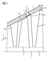
- the FIG. 1 shows a part of an inner housing construction 1, which is rotationally symmetrical about a rotation axis 2 is formed.
- the inner housing construction may be, for example, a vane ring.
- a rotor 3 is rotatably mounted about the axis of rotation 2 and comprises at least one row of blades 4 (further rows of blades are not shown).
- a guide blade row 6 is arranged rotationally symmetrically about the rotation axis 2.
- a further row of guide blades 7 is arranged rotationally symmetrically about the axis of rotation 2.
- the inner housing construction 1 is intended for use in a turbomachine, for example a steam turbine.
- the inner housing construction 1 essentially comprises a load-bearing component of a material which has a comparatively large thickness 14. At least the thickness 14 is such that water jet cutting is not possible to incorporate a gap of comparatively small size.
- the inner casing structure 1 comprises a dewatering device 8, wherein the dewatering device 8 has a collecting slot 9.
- a hot vapor flows in the flow direction 5 and can lead to a condensation of small droplets on the blade row 4, which can impinge by centrifugal forces on an inner surface 10 of the inner housing structure 1.
- the dewatering device 8 is provided, which can aspirate the drops 10 striking the surface.
- the collecting slot 9 is introduced by conventional methods and has a large width 16, 18 corresponding to a method.
- a drainage screen 11 is arranged, wherein the drainage screen 11 has drainage slots 12 with the width 16 (in FIG FIG. 1 not shown in detail).
- the drainage screen 11 is arranged in a groove 13 in the inner housing structure 1.
- the drainage screen 11 consists of a thin sheet, the drainage slots 12 are made by water jet cutting. Alternatively, other manufacturing methods can be used.
- the thickness 14 of the drainage screen 11 and the depth 15 of the groove 13 are chosen such that the surface 10 of the inner housing structure is continuously formed.
- the drainage screen 11 is welded by a welding process in the groove 13.
- the width 16, 18 of the drainage slots 12 is in this case between 1 and 2 mm.
- the collecting slot 9 is formed as an annular gap and is connected by bores or slots with a pressure chamber of lower pressure.
- steam located in front of the dewatering screen 11 is drawn in toward the inner housing structure 1.
- Via further lines of the steam passes to a drainage unit (not shown).
- the inner casing construction 1 and the drainage screen 11 may be made of a same material.
- the drainage screen 11 may comprise a different material than the inner housing construction 1.
- the material of the drainage screen 11 may be a high alloy steel.
- FIG. 2 shows a part of the inner housing construction 1. To see is a part of the drainage screen 11, which is formed circumferentially in a circumferential direction 17.
- FIG. 3 shows an enlarged cross-sectional view of the Enticassungsvorraum 8.
- the collecting slot 9 has a width 18.
- the groove 13 which is in in FIG. 3 illustrated example, two stages, which means that basically a second groove 13a is arranged.
- the drainage screen 11 is arranged in the second groove 13 a.
- the drainage screen 11 is welded into the groove 13a.
- FIG. 4 shows a side view of the drainage screen 11.
- the drainage screen 11 has a plurality of arranged in the circumferential direction 17 drainage slots 12.
- the drainage slots 12 have a width 16, 18 between 1 mm and 2 mm and are arranged to ensure a circumferentially same effect ideally offset from each other.
- Seen in the circumferential direction 17, the drainage slots 12 are in arranged at an equal distance 21.
- the second row in the circumferential direction 17 of the drainage slots 12 each have been selected an equal distance 21.
- FIG. 5 shows a cross-sectional view of in FIG. 4 shown drainage aperture 11.
Landscapes
- Engineering & Computer Science (AREA)
- Mechanical Engineering (AREA)
- General Engineering & Computer Science (AREA)
- Turbine Rotor Nozzle Sealing (AREA)
Priority Applications (2)
| Application Number | Priority Date | Filing Date | Title |
|---|---|---|---|
| EP14170959.2A EP2952700A1 (fr) | 2014-06-03 | 2014-06-03 | Agencement de boîtier intérieur pour une turbomachine et procédé associé de manufacture |
| PCT/EP2015/059285 WO2015185294A1 (fr) | 2014-06-03 | 2015-04-29 | Structure de boîtier intérieur pour turbomachine et son procédé de fabrication |
Applications Claiming Priority (1)
| Application Number | Priority Date | Filing Date | Title |
|---|---|---|---|
| EP14170959.2A EP2952700A1 (fr) | 2014-06-03 | 2014-06-03 | Agencement de boîtier intérieur pour une turbomachine et procédé associé de manufacture |
Publications (1)
| Publication Number | Publication Date |
|---|---|
| EP2952700A1 true EP2952700A1 (fr) | 2015-12-09 |
Family
ID=50884731
Family Applications (1)
| Application Number | Title | Priority Date | Filing Date |
|---|---|---|---|
| EP14170959.2A Withdrawn EP2952700A1 (fr) | 2014-06-03 | 2014-06-03 | Agencement de boîtier intérieur pour une turbomachine et procédé associé de manufacture |
Country Status (2)
| Country | Link |
|---|---|
| EP (1) | EP2952700A1 (fr) |
| WO (1) | WO2015185294A1 (fr) |
Citations (7)
| Publication number | Priority date | Publication date | Assignee | Title |
|---|---|---|---|---|
| GB388156A (en) * | 1930-12-13 | 1933-02-23 | Asea Ab | Improvements in means for draining off moisture from the steam in steam turbines |
| DE2038047A1 (de) * | 1970-07-31 | 1972-02-03 | Maschf Augsburg Nuernberg Ag | Entwässerung der Oberflachen der Leitschaufeln und des Stromungsraumes von Dampfturbinen, insbesondere Satt und Naßdampfturbinen |
| CA1006448A (en) * | 1971-09-09 | 1977-03-08 | Ukrainsky Nauchno-Issledovatelsky Institut Prirodnykh Gazov | Turboexpander |
| GB1484289A (en) * | 1975-09-26 | 1977-09-01 | English Electric Co Ltd | Steam turbines |
| DD200633A1 (de) * | 1981-08-24 | 1983-05-25 | Herbert Schulze | Anordnung zur entwaesserung der nassdampfstroemungen in dampfturbinen axialer bauart |
| JPH0337303A (ja) * | 1989-07-05 | 1991-02-18 | Hitachi Ltd | 蒸気タービン |
| JP2001090506A (ja) * | 1999-09-22 | 2001-04-03 | Hitachi Ltd | 静翼及び蒸気タービン |
-
2014
- 2014-06-03 EP EP14170959.2A patent/EP2952700A1/fr not_active Withdrawn
-
2015
- 2015-04-29 WO PCT/EP2015/059285 patent/WO2015185294A1/fr not_active Ceased
Patent Citations (7)
| Publication number | Priority date | Publication date | Assignee | Title |
|---|---|---|---|---|
| GB388156A (en) * | 1930-12-13 | 1933-02-23 | Asea Ab | Improvements in means for draining off moisture from the steam in steam turbines |
| DE2038047A1 (de) * | 1970-07-31 | 1972-02-03 | Maschf Augsburg Nuernberg Ag | Entwässerung der Oberflachen der Leitschaufeln und des Stromungsraumes von Dampfturbinen, insbesondere Satt und Naßdampfturbinen |
| CA1006448A (en) * | 1971-09-09 | 1977-03-08 | Ukrainsky Nauchno-Issledovatelsky Institut Prirodnykh Gazov | Turboexpander |
| GB1484289A (en) * | 1975-09-26 | 1977-09-01 | English Electric Co Ltd | Steam turbines |
| DD200633A1 (de) * | 1981-08-24 | 1983-05-25 | Herbert Schulze | Anordnung zur entwaesserung der nassdampfstroemungen in dampfturbinen axialer bauart |
| JPH0337303A (ja) * | 1989-07-05 | 1991-02-18 | Hitachi Ltd | 蒸気タービン |
| JP2001090506A (ja) * | 1999-09-22 | 2001-04-03 | Hitachi Ltd | 静翼及び蒸気タービン |
Also Published As
| Publication number | Publication date |
|---|---|
| WO2015185294A1 (fr) | 2015-12-10 |
Similar Documents
| Publication | Publication Date | Title |
|---|---|---|
| EP2179143B1 (fr) | Refroidissement de fente entre une paroi de chambre de combustion et une paroi de turbine d'une installation de turbine à gaz | |
| DE102010037862A1 (de) | Wirbelkammern zur Spaltströmungssteuerung | |
| DE112020000964B4 (de) | Turbinenleitschaufel und dampfturbine | |
| DE102015100874A1 (de) | Dichtungseinrichtung zur Erbringung einer Abdichtung in einer Turbomaschine | |
| EP2696029A1 (fr) | Grille d'aube avec définition de contour de la paroi latérale et turbomachine | |
| DE112020000950B4 (de) | Turbinenleitschaufel und dampfturbine | |
| EP3336313A1 (fr) | Ensemble d'aube mobile pour turbines d'une turbine turbine à gaz et procédé de fourniture d'air sceau dans un ensemble d'aube mobile pour turbines | |
| WO2017029008A1 (fr) | Refroidissement de rotor pour turbine à vapeur | |
| EP2647796A1 (fr) | Système d'étanchéité pour turbomachine | |
| DE102017212311A1 (de) | Umströmungsanordung zum Anordnen im Heißgaskanal einer Strömungsmaschine | |
| EP3401504B1 (fr) | Grille d'aube | |
| DE102009003526B4 (de) | Vorrichtung und Verfahren zur Kühlung des Einlaufbereichs einer Zweistromturbine | |
| DE102010031213A1 (de) | Rotor einer Turbomaschine | |
| EP2526263B1 (fr) | Système de boîtier pour une turbomachine axiale | |
| DE112017006877T5 (de) | Dampfturbine | |
| EP3022393A1 (fr) | Rotor pour une turbomachine thermique | |
| EP2601382B1 (fr) | Circuit d'arrêt de turbines à vapeur pour arrêter la vapeur humide | |
| EP3312388B1 (fr) | Pièce de rotor, compresseur, turbine et procédé de fabrication associés | |
| DE102010044819B4 (de) | Axialturbine und ein Verfahren zum Abführen eines Stroms von einer Axialturbine | |
| EP2952700A1 (fr) | Agencement de boîtier intérieur pour une turbomachine et procédé associé de manufacture | |
| EP3231999A1 (fr) | Aube directrice dote de pale refroidie par couche d'air | |
| DE102019220028B4 (de) | Axialturbine | |
| CH714650B1 (de) | Radialverdichter. | |
| DE102021207695B4 (de) | Hohle Dampfturbinenschaufel | |
| EP2675999B1 (fr) | Turbine a vapeur avec piston de compensation axial et agencement d'etancheite pour le blocage de vapeur saturee |
Legal Events
| Date | Code | Title | Description |
|---|---|---|---|
| PUAI | Public reference made under article 153(3) epc to a published international application that has entered the european phase |
Free format text: ORIGINAL CODE: 0009012 |
|
| AK | Designated contracting states |
Kind code of ref document: A1 Designated state(s): AL AT BE BG CH CY CZ DE DK EE ES FI FR GB GR HR HU IE IS IT LI LT LU LV MC MK MT NL NO PL PT RO RS SE SI SK SM TR |
|
| AX | Request for extension of the european patent |
Extension state: BA ME |
|
| STAA | Information on the status of an ep patent application or granted ep patent |
Free format text: STATUS: THE APPLICATION IS DEEMED TO BE WITHDRAWN |
|
| 18D | Application deemed to be withdrawn |
Effective date: 20160610 |