EP2952721A1 - Steuerungsvorrichtung für einen verbrennungsmotor - Google Patents
Steuerungsvorrichtung für einen verbrennungsmotor Download PDFInfo
- Publication number
- EP2952721A1 EP2952721A1 EP13873938.8A EP13873938A EP2952721A1 EP 2952721 A1 EP2952721 A1 EP 2952721A1 EP 13873938 A EP13873938 A EP 13873938A EP 2952721 A1 EP2952721 A1 EP 2952721A1
- Authority
- EP
- European Patent Office
- Prior art keywords
- fuel ratio
- air
- exhaust
- output current
- reference cell
- Prior art date
- Legal status (The legal status is an assumption and is not a legal conclusion. Google has not performed a legal analysis and makes no representation as to the accuracy of the status listed.)
- Granted
Links
- 238000002485 combustion reaction Methods 0.000 title claims abstract description 58
- 239000000446 fuel Substances 0.000 claims abstract description 842
- 239000007789 gas Substances 0.000 claims abstract description 348
- 239000001301 oxygen Substances 0.000 claims abstract description 233
- 229910052760 oxygen Inorganic materials 0.000 claims abstract description 233
- QVGXLLKOCUKJST-UHFFFAOYSA-N atomic oxygen Chemical compound [O] QVGXLLKOCUKJST-UHFFFAOYSA-N 0.000 claims abstract description 206
- 239000003054 catalyst Substances 0.000 claims description 187
- 238000011144 upstream manufacturing Methods 0.000 claims description 179
- 238000000746 purification Methods 0.000 claims description 177
- 239000007784 solid electrolyte Substances 0.000 claims description 52
- 238000009792 diffusion process Methods 0.000 claims description 51
- 230000001105 regulatory effect Effects 0.000 claims description 49
- 238000001514 detection method Methods 0.000 claims description 30
- 230000008859 change Effects 0.000 claims description 27
- 230000007423 decrease Effects 0.000 claims description 21
- 230000015556 catabolic process Effects 0.000 claims description 10
- 230000003247 decreasing effect Effects 0.000 claims description 8
- PNEYBMLMFCGWSK-UHFFFAOYSA-N aluminium oxide Inorganic materials [O-2].[O-2].[O-2].[Al+3].[Al+3] PNEYBMLMFCGWSK-UHFFFAOYSA-N 0.000 claims description 3
- 239000010410 layer Substances 0.000 description 97
- MWUXSHHQAYIFBG-UHFFFAOYSA-N nitrogen oxide Inorganic materials O=[N] MWUXSHHQAYIFBG-UHFFFAOYSA-N 0.000 description 51
- -1 oxygen ions Chemical class 0.000 description 28
- 238000002347 injection Methods 0.000 description 23
- 239000007924 injection Substances 0.000 description 23
- 230000003197 catalytic effect Effects 0.000 description 6
- 230000032683 aging Effects 0.000 description 5
- BASFCYQUMIYNBI-UHFFFAOYSA-N platinum Chemical compound [Pt] BASFCYQUMIYNBI-UHFFFAOYSA-N 0.000 description 5
- CPLXHLVBOLITMK-UHFFFAOYSA-N Magnesium oxide Chemical compound [Mg]=O CPLXHLVBOLITMK-UHFFFAOYSA-N 0.000 description 4
- MCMNRKCIXSYSNV-UHFFFAOYSA-N Zirconium dioxide Chemical compound O=[Zr]=O MCMNRKCIXSYSNV-UHFFFAOYSA-N 0.000 description 4
- 230000007246 mechanism Effects 0.000 description 4
- 239000000126 substance Substances 0.000 description 4
- VYPSYNLAJGMNEJ-UHFFFAOYSA-N Silicium dioxide Chemical compound O=[Si]=O VYPSYNLAJGMNEJ-UHFFFAOYSA-N 0.000 description 2
- 230000009471 action Effects 0.000 description 2
- WMWLMWRWZQELOS-UHFFFAOYSA-N bismuth(iii) oxide Chemical compound O=[Bi]O[Bi]=O WMWLMWRWZQELOS-UHFFFAOYSA-N 0.000 description 2
- CETPSERCERDGAM-UHFFFAOYSA-N ceric oxide Chemical compound O=[Ce]=O CETPSERCERDGAM-UHFFFAOYSA-N 0.000 description 2
- 229910000422 cerium(IV) oxide Inorganic materials 0.000 description 2
- 230000007812 deficiency Effects 0.000 description 2
- 230000003111 delayed effect Effects 0.000 description 2
- 238000010586 diagram Methods 0.000 description 2
- 230000006870 function Effects 0.000 description 2
- 239000000395 magnesium oxide Substances 0.000 description 2
- 238000004519 manufacturing process Methods 0.000 description 2
- 238000000034 method Methods 0.000 description 2
- 229910052697 platinum Inorganic materials 0.000 description 2
- 239000010970 precious metal Substances 0.000 description 2
- 239000011241 protective layer Substances 0.000 description 2
- 229910004369 ThO2 Inorganic materials 0.000 description 1
- 230000003213 activating effect Effects 0.000 description 1
- 230000004913 activation Effects 0.000 description 1
- 230000002457 bidirectional effect Effects 0.000 description 1
- 230000033228 biological regulation Effects 0.000 description 1
- ODINCKMPIJJUCX-UHFFFAOYSA-N calcium oxide Inorganic materials [Ca]=O ODINCKMPIJJUCX-UHFFFAOYSA-N 0.000 description 1
- 239000000919 ceramic Substances 0.000 description 1
- 238000006243 chemical reaction Methods 0.000 description 1
- 230000001276 controlling effect Effects 0.000 description 1
- KZHJGOXRZJKJNY-UHFFFAOYSA-N dioxosilane;oxo(oxoalumanyloxy)alumane Chemical compound O=[Si]=O.O=[Si]=O.O=[Al]O[Al]=O.O=[Al]O[Al]=O.O=[Al]O[Al]=O KZHJGOXRZJKJNY-UHFFFAOYSA-N 0.000 description 1
- 230000000694 effects Effects 0.000 description 1
- CJNBYAVZURUTKZ-UHFFFAOYSA-N hafnium(IV) oxide Inorganic materials O=[Hf]=O CJNBYAVZURUTKZ-UHFFFAOYSA-N 0.000 description 1
- 238000010438 heat treatment Methods 0.000 description 1
- 229910052741 iridium Inorganic materials 0.000 description 1
- 239000007788 liquid Substances 0.000 description 1
- 229910052863 mullite Inorganic materials 0.000 description 1
- 239000011148 porous material Substances 0.000 description 1
- 230000008569 process Effects 0.000 description 1
- 239000000377 silicon dioxide Substances 0.000 description 1
- 239000007787 solid Substances 0.000 description 1
- 239000000243 solution Substances 0.000 description 1
- 229910052596 spinel Inorganic materials 0.000 description 1
- 239000011029 spinel Substances 0.000 description 1
- 239000003381 stabilizer Substances 0.000 description 1
- ZCUFMDLYAMJYST-UHFFFAOYSA-N thorium dioxide Chemical compound O=[Th]=O ZCUFMDLYAMJYST-UHFFFAOYSA-N 0.000 description 1
- XLYOFNOQVPJJNP-UHFFFAOYSA-N water Substances O XLYOFNOQVPJJNP-UHFFFAOYSA-N 0.000 description 1
- FIXNOXLJNSSSLJ-UHFFFAOYSA-N ytterbium(III) oxide Inorganic materials O=[Yb]O[Yb]=O FIXNOXLJNSSSLJ-UHFFFAOYSA-N 0.000 description 1
- RUDFQVOCFDJEEF-UHFFFAOYSA-N yttrium(III) oxide Inorganic materials [O-2].[O-2].[O-2].[Y+3].[Y+3] RUDFQVOCFDJEEF-UHFFFAOYSA-N 0.000 description 1
Images




Classifications
-
- F—MECHANICAL ENGINEERING; LIGHTING; HEATING; WEAPONS; BLASTING
- F02—COMBUSTION ENGINES; HOT-GAS OR COMBUSTION-PRODUCT ENGINE PLANTS
- F02D—CONTROLLING COMBUSTION ENGINES
- F02D41/00—Electrical control of supply of combustible mixture or its constituents
- F02D41/02—Circuit arrangements for generating control signals
- F02D41/14—Introducing closed-loop corrections
- F02D41/1438—Introducing closed-loop corrections using means for determining characteristics of the combustion gases; Sensors therefor
- F02D41/1444—Introducing closed-loop corrections using means for determining characteristics of the combustion gases; Sensors therefor characterised by the characteristics of the combustion gases
- F02D41/1454—Introducing closed-loop corrections using means for determining characteristics of the combustion gases; Sensors therefor characterised by the characteristics of the combustion gases the characteristics being an oxygen content or concentration or the air-fuel ratio
- F02D41/1455—Introducing closed-loop corrections using means for determining characteristics of the combustion gases; Sensors therefor characterised by the characteristics of the combustion gases the characteristics being an oxygen content or concentration or the air-fuel ratio with sensor resistivity varying with oxygen concentration
-
- F—MECHANICAL ENGINEERING; LIGHTING; HEATING; WEAPONS; BLASTING
- F02—COMBUSTION ENGINES; HOT-GAS OR COMBUSTION-PRODUCT ENGINE PLANTS
- F02D—CONTROLLING COMBUSTION ENGINES
- F02D45/00—Electrical control not provided for in groups F02D41/00 - F02D43/00
-
- G—PHYSICS
- G01—MEASURING; TESTING
- G01N—INVESTIGATING OR ANALYSING MATERIALS BY DETERMINING THEIR CHEMICAL OR PHYSICAL PROPERTIES
- G01N27/00—Investigating or analysing materials by the use of electric, electrochemical, or magnetic means
- G01N27/26—Investigating or analysing materials by the use of electric, electrochemical, or magnetic means by investigating electrochemical variables; by using electrolysis or electrophoresis
- G01N27/403—Cells and electrode assemblies
- G01N27/406—Cells and probes with solid electrolytes
- G01N27/407—Cells and probes with solid electrolytes for investigating or analysing gases
- G01N27/41—Oxygen pumping cells
-
- F—MECHANICAL ENGINEERING; LIGHTING; HEATING; WEAPONS; BLASTING
- F02—COMBUSTION ENGINES; HOT-GAS OR COMBUSTION-PRODUCT ENGINE PLANTS
- F02D—CONTROLLING COMBUSTION ENGINES
- F02D41/00—Electrical control of supply of combustible mixture or its constituents
- F02D41/02—Circuit arrangements for generating control signals
- F02D41/021—Introducing corrections for particular conditions exterior to the engine
- F02D41/0235—Introducing corrections for particular conditions exterior to the engine in relation with the state of the exhaust gas treating apparatus
-
- F—MECHANICAL ENGINEERING; LIGHTING; HEATING; WEAPONS; BLASTING
- F02—COMBUSTION ENGINES; HOT-GAS OR COMBUSTION-PRODUCT ENGINE PLANTS
- F02D—CONTROLLING COMBUSTION ENGINES
- F02D41/00—Electrical control of supply of combustible mixture or its constituents
- F02D41/02—Circuit arrangements for generating control signals
- F02D41/14—Introducing closed-loop corrections
- F02D41/1438—Introducing closed-loop corrections using means for determining characteristics of the combustion gases; Sensors therefor
- F02D41/1473—Introducing closed-loop corrections using means for determining characteristics of the combustion gases; Sensors therefor characterised by the regulation method
-
- F—MECHANICAL ENGINEERING; LIGHTING; HEATING; WEAPONS; BLASTING
- F02—COMBUSTION ENGINES; HOT-GAS OR COMBUSTION-PRODUCT ENGINE PLANTS
- F02D—CONTROLLING COMBUSTION ENGINES
- F02D41/00—Electrical control of supply of combustible mixture or its constituents
- F02D41/02—Circuit arrangements for generating control signals
- F02D41/14—Introducing closed-loop corrections
- F02D41/1401—Introducing closed-loop corrections characterised by the control or regulation method
-
- F—MECHANICAL ENGINEERING; LIGHTING; HEATING; WEAPONS; BLASTING
- F02—COMBUSTION ENGINES; HOT-GAS OR COMBUSTION-PRODUCT ENGINE PLANTS
- F02D—CONTROLLING COMBUSTION ENGINES
- F02D41/00—Electrical control of supply of combustible mixture or its constituents
- F02D41/02—Circuit arrangements for generating control signals
- F02D41/14—Introducing closed-loop corrections
- F02D41/1438—Introducing closed-loop corrections using means for determining characteristics of the combustion gases; Sensors therefor
- F02D41/1439—Introducing closed-loop corrections using means for determining characteristics of the combustion gases; Sensors therefor characterised by the position of the sensor
- F02D41/1441—Plural sensors
-
- F—MECHANICAL ENGINEERING; LIGHTING; HEATING; WEAPONS; BLASTING
- F02—COMBUSTION ENGINES; HOT-GAS OR COMBUSTION-PRODUCT ENGINE PLANTS
- F02D—CONTROLLING COMBUSTION ENGINES
- F02D41/00—Electrical control of supply of combustible mixture or its constituents
- F02D41/02—Circuit arrangements for generating control signals
- F02D41/14—Introducing closed-loop corrections
- F02D41/1438—Introducing closed-loop corrections using means for determining characteristics of the combustion gases; Sensors therefor
- F02D41/1444—Introducing closed-loop corrections using means for determining characteristics of the combustion gases; Sensors therefor characterised by the characteristics of the combustion gases
- F02D41/1454—Introducing closed-loop corrections using means for determining characteristics of the combustion gases; Sensors therefor characterised by the characteristics of the combustion gases the characteristics being an oxygen content or concentration or the air-fuel ratio
- F02D41/1456—Introducing closed-loop corrections using means for determining characteristics of the combustion gases; Sensors therefor characterised by the characteristics of the combustion gases the characteristics being an oxygen content or concentration or the air-fuel ratio with sensor output signal being linear or quasi-linear with the concentration of oxygen
Definitions
- the present invention relates to a control system of an internal combustion engine which controls the internal combustion engine in accordance with the output of an air-fuel ratio sensor.
- Such air-fuel ratio sensors may be roughly divided into single-cell types of air-fuel ratio sensors (for example, PLTs 2 and 4) and double-cell types of air-fuel ratio sensors (for example, PLTs 1, 3, and 5).
- a single-cell type of air-fuel ratio sensor only a single cell comprised of a solid electrolyte layer which can pass oxygen ions and two electrodes which are provided on both side surfaces of the layer, is provided. One of the electrodes thereof is exposed to the atmosphere, while the other electrode is exposed to the exhaust gas through a diffusion regulating layer.
- voltage is applied across two electrodes which are arranged on the both side surfaces of the solid electrolyte layer.
- the air-fuel ratio of the exhaust gas (below, also referred to as the "exhaust air-fuel ratio") is detected (for example, PLT 2).
- a double-cell type of air-fuel ratio sensor two cells, each comprised of a solid electrolyte layer which can pass oxygen ions and two electrodes which are provided on both side surfaces of the layer, are provided.
- One cell (reference cell) among these is configured so that the detected voltage (electromotive force) changes in accordance with a concentration of oxygen in exhaust gas in a measured gas chamber.
- the other cell pumps oxygen in and pumps it out with respect to the exhaust gas in the measured gas chamber, in accordance with a pump current.
- the pump current of the pump cell is set so as to pump in oxygen and pump it out so as to make the detected voltage which is detected at the reference cell conform to a target voltage value. By detecting this pump current, the exhaust air-fuel ratio is detected.
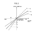
- the air-fuel ratio sensor such as described in PLTs 1-5 is generally configured to have the output characteristic which is shown by the solid line A in FIG. 2 . That is, in this air-fuel ratio sensor, the larger the exhaust air-fuel ratio (that is, the leaner), the larger the output current from the air-fuel ratio sensor. In addition, this air-fuel ratio sensor is configured so that the output current becomes zero when the exhaust air-fuel ratio is the stoichiometric air-fuel ratio.
- the slant in FIG. 2 that is, the ratio of the amount of increase of the output current to the amount of increase of the exhaust air-fuel ratio (below, the "rate of change of output current" is not necessarily the same even if produced through a similar production process. Even with the same model of air-fuel ratio sensors, differences occur between the individual sensors. In addition, even at the same air-fuel ratio sensor, aging, etc., cause the changing rate of output current to change. As a result, even if using the same type of sensors, depending on the sensor used or period of use, etc., as shown in FIG. 2 by the broken line B, the changing rate of output current becomes smaller or, as shown by the one-dot chain line C, the changing rate of output current becomes larger.
- the output current of the air-fuel ratio sensor will differ depending on the sensor used, the duration of usage, etc.
- the air-fuel ratio sensor has the output characteristic such as shown by the solid line A
- the output current becomes I 2 when measuring exhaust gas with the air-fuel ratio af 1 .
- the air-fuel ratio sensor has the output characteristics such as shown by the broken line B and the one-dot chain line C
- the output currents become respectively I 1 and I 3 , which are different from the above-mentioned I 2 , when measuring exhaust gas with the air-fuel ratio af 1 .
- this air-fuel ratio sensor it is possible to accurately detect the stoichiometric air-fuel ratio and rich and lean with respect to the stoichiometric air-fuel ratio, but when the air-fuel ratio of the exhaust gas is not the stoichiometric air-fuel ratio, the absolute value (that is, rich degree or lean degree) could not be accurately detected.
- an object of the present invention is to provide a control system of an internal combustion engine which uses an air-fuel ratio sensor which can detect an absolute value of an air-fuel ratio of the exhaust gas, even when the air-fuel ratio thereof is not a stoichiometric air-fuel ratio.
- a control system of an internal combustion engine comprising: an air-fuel ratio sensor which is provided in an exhaust passage of the internal combustion engine, and an engine control device which controls the internal combustion engine based on a sensor output current of the air-fuel ratio sensor, wherein the air-fuel ratio sensor comprises: a measured gas chamber into which exhaust gas, for which the air-fuel ratio is to be detected, flows; a reference cell with a reference cell output current which changes in accordance with the air-fuel ratio of the exhaust gas in the measured gas chamber; and a pump cell which pumps in oxygen and pumps it out with respect to exhaust gas in the measured gas chamber in accordance with a pump current, the reference cell is configured so that the applied voltage, by which the reference cell output current becomes zero, changes in accordance with the air-fuel ratio of the exhaust gas in the measured gas chamber and so that, when the air-fuel ratio of the exhaust gas in the measured gas chamber is the stoichiometric air-fuel ratio, if increasing the applied voltage at
- the reference cell comprises: a first electrode which is exposed to exhaust gas in the measured gas chamber; a second electrode which is exposed to a reference atmosphere; and a solid electrolyte layer which is arranged between the first electrode and the second electrode, and the air-fuel ratio sensor further comprises a diffusion regulating layer, the diffusion regulating layer being arranged so that exhaust gas reaches the first electrode through the diffusion regulating layer.
- the diffusion regulating layer is arranged so that exhaust gas in the measured gas chamber reaches the first electrode through the diffusion regulating layer.
- any one of the first to third aspects of the invention wherein the reference cell is configured so as to have, for each exhaust air-fuel ratio, a limit current region which is a voltage region where the reference cell output current becomes a limit current, and the constant voltage is a voltage within the limit current region when the exhaust air-fuel ratio is the stoichiometric air-fuel ratio.
- any one of the first to third aspects of the invention wherein the reference cell is configured to have, for each exhaust air-fuel ratio, regarding the relationship between the applied voltage and reference cell output current, a proportional region which is a voltage region where the reference cell output current increases in proportion to an increase of the applied voltage, a moisture breakdown region which is a voltage region where the reference cell output current changes in accordance with a change of the applied voltage due to the breakdown of moisture, and an intermediate region which is a voltage region between these proportional region and moisture breakdown region, and the constant voltage is a voltage within the intermediate region when the exhaust air-fuel ratio is the stoichiometric air-fuel ratio.
- any one of the first to third aspects of the invention wherein the constant voltage is set to a voltage between the voltage whereby the reference cell output current becomes zero when the exhaust air-fuel ratio is 1% higher than the stoichiometric air-fuel ratio and the voltage whereby the reference cell output current becomes zero when the air-fuel ratio of the exhaust gas in the measured gas chamber is 1% lower than the stoichiometric air-fuel ratio.
- any one of the first to third aspects of the invention wherein the reference cell is configured so that, for each exhaust air-fuel ratio, regarding the relationship between the applied voltage and reference cell output current, the reference cell output current increases up to a first curved point as the applied voltage increases, the reference cell output current increases from the first curved point to a second curved point as the applied voltage increases, the reference cell output current increases from the second curved point as the applied voltage increases, and, in the voltage region between the first curved point and the second curved point, the amount of increase of the reference cell output current with respect to an amount of increase in the applied voltage becomes smaller than in other voltage regions, and the constant voltage is set to a voltage between the first curved point and the second curved point when the exhaust air-fuel ratio is the stoichiometric air-fuel ratio.
- the reference cell is configured so as to have, for each exhaust air-fuel ratio, a current increase region which is a voltage region where the reference cell output current increases along with an increase in the applied voltage, and current fine increase region which is a voltage region where an amount of increase of the reference cell output current with respect to an amount of increase of the applied voltage becomes smaller than the current increase region due to provision of the diffusion regulating layer, and the constant voltage is a voltage within the current fine increase region when the exhaust air-fuel ratio is the stoichiometric air-fuel ratio.
- the diffusion regulating layer is formed by alumina, and the constant voltage is set to 0.1V to 0.9V.
- any one of the first to ninth aspects of the invention wherein the engine control device judges that the exhaust air-fuel ratio is a predetermined air-fuel ratio which is different from the stoichiometric air-fuel ratio when the sensor output current of the air-fuel ratio sensor becomes zero.
- the internal combustion engine comprises an exhaust purification catalyst which is provided in the exhaust passage at the upstream side, in the direction of exhaust flow, from the air-fuel ratio sensor and which can store oxygen, and the constant voltage is set to a voltage by which the reference cell output current becomes zero when the exhaust air-fuel ratio is a predetermined rich judged air-fuel ratio which is richer than the stoichiometric air-fuel ratio.
- the engine control device can control the air-fuel ratio of the exhaust gas flowing into the exhaust purification catalyst and, when the sensor output current of the air-fuel ratio sensor becomes zero or less, the target air-fuel ratio of the exhaust gas flowing into the exhaust purification catalyst is set leaner than the stoichiometric air-fuel ratio.
- the engine control device comprises: an oxygen storage amount increasing means for continuously or intermittently setting a target air-fuel ratio of exhaust gas flowing into the exhaust purification catalyst leaner than the stoichiometric air-fuel ratio when the sensor output current of the air-fuel ratio sensor becomes zero or less, until the oxygen storage amount of the exhaust purification catalyst becomes a predetermined storage amount which is smaller than the maximum oxygen storage amount; and an oxygen storage amount decreasing means for continuously or intermittently setting the target air-fuel ratio richer than the stoichiometric air-fuel ratio when the oxygen storage amount of the exhaust purification catalyst becomes the predetermined storage amount or more, so that the oxygen storage amount never reaches the maximum oxygen storage amount but decreases toward zero.
- a difference between an average value of the target air-fuel ratio and the stoichiometric air-fuel ratio in the time period when the target air-fuel ratio is continuously or intermittently set leaner than the stoichiometric air-fuel ratio by the oxygen storage amount increasing means is larger than a difference between an average value of the target air-fuel ratio and the stoichiometric air-fuel ratio in the time period when the target air-fuel ratio is continuously or intermittently set richer than the stoichiometric air-fuel ratio by the oxygen storage amount decreasing means.
- control system of an internal combustion engine comprises an upstream side air-fuel ratio sensor which is provided in an engine exhaust passage at an upstream side, in the direction of exhaust flow, from the exhaust purification catalyst, and the engine control device controls the exhaust air-fuel ratio based on the output of the upstream side air-fuel ratio sensor so that the air-fuel ratio of the exhaust gas flowing into the exhaust purification catalyst becomes a target air-fuel ratio.
- the upstream side air-fuel ratio sensor is configured so that an applied voltage whereby a sensor output current becomes zero, changes in accordance with the exhaust air-fuel ratio and so that when the exhaust air-fuel ratio is a stoichiometric air-fuel ratio, if increasing the applied voltage at the upstream side air-fuel ratio sensor, the sensor output current increases along with that, and the applied voltage at the upstream side air-fuel ratio sensor is lower than the applied voltage of the air-fuel ratio sensor.
- the upstream side air-fuel ratio sensor detects the exhaust air-fuel ratio
- the applied voltage at the upstream side air-fuel ratio sensor is fixed to a constant voltage
- the constant voltage is set to a voltage whereby the sensor output current becomes zero when the air-fuel ratio of the exhaust gas in the measured chamber is the stoichiometric air-fuel ratio.
- a control system of an internal combustion engine which uses an air-fuel ratio sensor which can detect an absolute value of an air-fuel ratio of the exhaust gas, even when the air-fuel ratio thereof is not a stoichiometric air-fuel ratio.
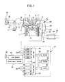
- FIG. 1 is a view which schematically shows an internal combustion engine in which a control device according to a first embodiment of the present invention is used.
- 1 indicates an engine body, 2 a cylinder block, 3 a piston which reciprocates inside the cylinder block 2, 4 a cylinder head which is fastened to the cylinder block 2, 5 a combustion chamber which is formed between the piston 3 and the cylinder head 4, 6 an intake valve, 7 an intake port, 8 an exhaust valve, and 9 an exhaust port.
- the intake valve 6 opens and closes the intake port 7, while the exhaust valve 8 opens and closes the exhaust port 9.
- a spark plug 10 is arranged at a center part of an inside wall surface of the cylinder head 4, while a fuel injector 11 is arranged at a side part of the inner wall surface of the cylinder head 4.
- the spark plug 10 is configured to generate a spark in accordance with an ignition signal.
- the fuel injector 11 injects a predetermined amount of fuel into the combustion chamber 5 in accordance with an injection signal.
- the fuel injector 11 may also be arranged so as to inject fuel into the intake port 7.
- the fuel gasoline with a stoichiometric air-fuel ratio of 14.6 at an exhaust purification catalyst is used.
- the internal combustion engine of the present invention may also use another fuel.
- the intake port 7 of each cylinder is connected to a surge tank 14 through a corresponding intake branch pipe 13, while the surge tank 14 is connected to an air cleaner 16 through an intake pipe 15.
- the intake port 7, intake branch pipe 13, surge tank 14, and intake pipe 15 form an intake passage.
- a throttle valve 18 which is driven by a throttle valve drive actuator 17 is arranged inside the intake pipe 15.
- the throttle valve 18 can be operated by the throttle valve drive actuator 17 to thereby change the aperture area of the intake passage.
- the exhaust port 9 of each cylinder is connected to an exhaust manifold 19.
- the exhaust manifold 19 has a plurality of branch pipes which are connected to the exhaust ports 9 and a header at which these branch pipes are collected.
- the header of the exhaust manifold 19 is connected to an upstream side casing 21 which houses an upstream side exhaust purification catalyst 20.
- the upstream side casing 21 is connected through an exhaust pipe 22 to a downstream side casing 23 which houses a downstream side exhaust purification catalyst 24.
- the exhaust port 9, exhaust manifold 19, upstream side casing 21, exhaust pipe 22, and downstream side casing 23 form an exhaust passage.
- the electronic control unit (ECU) 31 is comprised of a digital computer which is provided with components which are connected together through a bidirectional bus 32 such as a RAM (random access memory) 33, ROM (read only memory) 34, CPU (microprocessor) 35, input port 36, and output port 37.
- a RAM random access memory
- ROM read only memory
- CPU microprocessor
- input port 36 input port 36
- output port 37 output port 37
- an air flow meter 39 is arranged for detecting the flow rate of air flowing through the intake pipe 15.
- the output of this air flow meter 39 is input through a corresponding AD converter 38 to the input port 36.
- an upstream side air-fuel ratio sensor 40 is arranged which detects the air-fuel ratio of the exhaust gas flowing through the inside of the exhaust manifold 19 (that is, the exhaust gas flowing into the upstream side exhaust purification catalyst 20).
- a downstream side air-fuel ratio sensor 41 is arranged which detects the air-fuel ratio of the exhaust gas flowing through the inside of the exhaust pipe 22 (that is, the exhaust gas flowing out from the upstream side exhaust purification catalyst 20 and flows into the downstream side exhaust purification catalyst 24).
- the outputs of these air-fuel ratio sensors 40 and 41 are also input through the corresponding AD converters 38 to the input port 36. Note that, the configurations of these air-fuel ratio sensors 40 and 41 will be explained later.
- an accelerator pedal 42 has a load sensor 43 connected to it which generates an output voltage which is proportional to the amount of depression of the accelerator pedal 42.
- the output voltage of the load sensor 43 is input to the input port 36 through a corresponding AD converter 38.
- the crank angle sensor 44 generates an output pulse every time, for example, a crankshaft rotates by 15 degrees. This output pulse is input to the input port 36.
- the CPU 35 calculates the engine speed from the output pulse of this crank angle sensor 44.
- the output port 37 is connected through corresponding drive circuits 45 to the spark plugs 10, fuel injectors 11, and throttle valve drive actuator 17. Note that the ECU 31 functions as an engine control system for controlling the internal combustion engine based on the outputs of various sensors, etc.
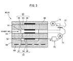
- FIG. 3 is a schematic cross-sectional view of air-fuel ratio sensors 40 and 41.
- the air-fuel ratio sensors 40 and 41 in the present embodiment are double-cell type air-fuel ratio sensors each comprised of a solid electrolyte layer and a pair of electrodes forming a double cell.
- each of the air-fuel ratio sensors 40, 41 comprises a measured gas chamber 51, a reference gas chamber 52, and two solid electrolyte layers 53, 54 which are arranged at the both sides of the measured gas chamber 51.
- the reference gas chamber 52 is provided at the opposite side of the measured gas chamber 51 across the second solid electrolyte layer 54.
- a gas chamber side electrode (third electrode) 55 is arranged, while on the side surface of the first solid electrolyte layer 53 at the exhaust gas side, an exhaust side electrode (fourth electrode) 56 is arranged.
- These first solid electrolyte layer 53, gas chamber side electrode 55, and exhaust side electrode 56 configure a pump cell 60.
- a gas chamber side electrode (first electrode) 57 is arranged on the side surface of the second solid electrolyte layer 54 at the measured gas chamber 51 side, while on the side surface of the second solid electrolyte layer 54 at the reference gas chamber 52 side, a reference side electrode (second electrode) 58 is arranged.
- first electrode first electrode
- second electrode second electrode
- a diffusion regulating layer 63 is provided so as to surround the gas chamber side electrode 55 of the pump cell 60 and the gas chamber side electrode 57 of the reference cell 61. Therefore, the measured gas chamber 51 is defined by the first solid electrolyte layer 53, the second solid electrolyte layer 54, and the diffusion regulating layer 63.
- exhaust gas flows through the diffusion regulating layer 63. Accordingly, the electrodes arranged in the measured gas chamber 51, that is, the gas chamber side electrode 55 of the pump cell 60 and the gas chamber side electrode 57 of the reference cell 61, are exposed through the diffusion regulating layer 63 to the exhaust gas.
- the diffusion regulating layer 63 does not necessarily have to be provided so that exhaust gas flowing into the measured gas chamber 51 can pass through the diffusion regulating layer 63. So long as the exhaust gas which reaches the gas chamber side electrode 57 of the reference cell 61 is exhaust gas which passes through the diffusion regulating layer, the diffusion regulating layer may be arranged in any manner.
- a heater part 64 is provided so as to surround the reference gas chamber 52. Therefore, the reference gas chamber 52 is defined by the second solid electrolyte layer 54 and the heater part 64. In this reference gas chamber 52, reference gas is introduced. In the present embodiment, the reference gas chamber 52 is opened to the atmosphere. Accordingly, inside the reference gas chamber 52, atmospheric air is introduced as reference gas.
- the heater part 64 is provided with a plurality of heaters 65. These heaters 65 can be used to control the temperature of the air-fuel ratio sensors 40, 41, in particular the temperature of the solid electrolyte layers 53, 54.
- the heater part 65 has a sufficient heat generating capacity for heating the solid electrolyte layers 53, 54 until activating.
- a protective layer 66 is provided on the side surface of the first solid electrolyte layer 53 at the exhaust gas side.
- the protective layer 66 is formed from a porous material so that liquid in the exhaust gas, etc., is prevented from directly sticking to the exhaust side electrode 56 while the exhaust gas reaches the exhaust side electrode 56.
- the solid electrolyte layers 53, 54 are formed by a sintered body of ZrO 2 (zirconia), HfO 2 , ThO 2 , Bi 2 O 3 , or other oxygen ion conducting oxide in which CaO, MgO, Y 2 O 3 , Yb 2 O 3 , etc., is blended as a stabilizer.
- the diffusion regulation layer 63 is formed by a porous sintered body of alumina, magnesia, silica, spinel, mullite, or other heat resistant inorganic substances.
- the electrodes 55-58 is formed by platinum or other precious metal with a high catalytic activity.
- sensor applied voltage Vr is applied by the reference cell voltage application device 70 which is mounted in the ECU 31.
- the ECU 31 is provided with a reference cell output current detection device 71 which detects the reference cell output current Ir flowing across these electrodes 57, 58 through the second solid electrolyte layer 54 when the reference cell voltage application device 70 applies the sensor applied voltage Vr.
- pump voltage Vp is applied by a pump voltage application device 72 which is mounted in the ECU 31.
- the pump voltage Vp applied by the pump voltage application device 72 is set in accordance with the reference cell output current Ir detected by the reference cell output current detection device 71.
- the pump voltage Vp is set in accordance with the difference between the reference cell output current Ir detected by the reference cell output current detection device 71 and the preset target current (for example, zero).
- the ECU 31 is provided with a pump current detection device 73 which detects a pump current Ip which flows across these electrodes 55 and 56 through the first solid electrolyte layer 53 when the pump voltage application device 72 applies the pump voltage Vp.
- the pump voltage application device 72 changes the pump voltage Vp, the pump current Ip which flows across the electrodes 85, 86 changes. In other words, the pump voltage application device 72 can be said to control the pump current Ip. Therefore, the pump voltage application device 72 acts as a pump current control device which controls the pump current Ip.
- the pump current Ip for example, changes by arranging a variable resistor in series with the pump voltage application device 72 and changing this variable resistor. Therefore, as the pump current control device, a variable resistor or other means other than the pump voltage application device 72 may be used.
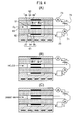
- FIG. 4 is a view which schematically shows the operation of the air-fuel ratio sensors 40, 41.
- each of the air-fuel ratio sensors 40, 41 is arranged so that the protection layer 66 and the outer circumferential surface of the diffusion regulating layer 63 are exposed to the exhaust gas. Further, atmospheric air is introduced into the reference gas chamber 52 of the air-fuel ratio sensors 40, 41.
- the solid electrolyte layers 53, 54 is formed by a sintered body of an oxygen ion conductive oxide. Therefore, it has the property of an electromotive force E being generated which makes oxygen ions move from the high concentration side surface side to the low concentration side surface side if a difference occurs in the oxygen concentration between the two side surfaces of the solid electrolyte layers 53, 54 in the state activated by the high temperature (oxygen cell characteristic).
- the solid electrolyte layers 53, 54 has the characteristic of trying to make the oxygen ions move so that a ratio of oxygen concentration occurs between the two side surfaces of the solid electrolyte layer in accordance with the potential difference (oxygen pump characteristic). Specifically, when a potential difference occurs across the two side surfaces, movement of oxygen ions is caused so that the oxygen concentration at the side surface which has a positive polarity becomes higher than the oxygen concentration at the side surface which has a negative polarity, by a ratio according to the potential difference.
- the pump voltage application device 72 applies the pump voltage Vp across the gas chamber side electrode 55 and the exhaust side electrode 56, movement of oxygen ions occurs corresponding to this. Along which such movement of oxygen ions, oxygen is pumped into or pumped out of the exhaust gas in the measured gas chamber 51.
- the reference cell 61 in the present embodiment by means of the mechanism mentioned below, when the air-fuel ratio of the exhaust gas in the measured gas chamber 81 conforms to the rich judged air-fuel ratio (predetermined air-fuel ratio slightly richer than the stoichiometric air-fuel ratio; for example, 14.55), the reference cell output current flowing across the electrodes 57 and 58 becomes zero.
- the reference cell output current flowing across the electrodes 57 and 58 becomes a negative current with a magnitude which is proportional to the difference from the rich judged air-fuel ratio.
- the reference cell output current which flows across the electrodes 57 and 58 becomes a positive current with a magnitude which is proportional to the difference from the rich judged air-fuel ratio.
- the pump voltage application device 72 applies pump voltage to the electrodes 55 and 56 of the pump cell 60.
- pump voltage is applied using the exhaust side electrode 56 as the positive electrode and the gas chamber side electrode 855 as the negative electrode.
- the flow rate of oxygen pumped out from inside each measured gas chamber 51 to the exhaust gas around the air-fuel ratio sensors 40, 41 is proportional to the pump voltage. Further, the pump voltage is proportional to the magnitude of the positive reference cell output current detected by the reference cell output current detection device 71. Therefore, the larger the lean degree of the exhaust air-fuel ratio in the measured gas chamber 51, that is, the higher the concentration of oxygen in the measured gas chamber 51, the greater the flow rate of oxygen pumped out from the inside of the measured gas chamber 51 into the exhaust gas around the air-fuel ratio sensors 40, 41. As a result, the flow rate of oxygen flowing through the diffusion regulating layer 63 into the measured gas chamber 51 and the flow rate of oxygen pumped out by the pump cell 60 basically conform to each other. Therefore, the air-fuel ratio in the measured gas chamber 51, is basically maintained substantially at the rich judged air-fuel ratio.
- the flow rate of oxygen pumped by the pump cell 60 equals the flow rate of oxygen ions which move through the inside of the first solid electrolyte layer 53 of the pump cell 60. Further, the flow rate of the oxygen ions is equal to the current which flows across the electrodes 55, 56 of the pump cell 60. Accordingly, by detecting the pump current flowing across the electrodes 55, 56, as an output current of the air-fuel ratio sensors 40, 41 (hereinafter, referred to as "sensor output current"), by the pump current detection device 73, it is possible to detect the flow rate of oxygen flowing through the diffusion regulating layer 63 into the measured gas chamber 51, and thus a lean air-fuel ratio of the exhaust gas around the measured gas chamber 51.
- the reference cell output current detection device 71 detects the reference cell output current, based on this current, a pump voltage is applied across the electrodes 55 and 56 of the pump cell 60 by the pump voltage application device 72, by the mechanism mentioned below.
- pump voltage is applied using the gas chamber side electrode 55 as the positive electrode and the exhaust side electrode 56 as the negative electrode.
- the flow rate of oxygen pumped from the exhaust gas around the air-fuel ratio sensors 40, 41 into each measured gas chamber 51 is proportional to the pump voltage. Further, the pump voltage is proportional to the magnitude of the negative reference cell output current detected by the reference cell output current detection device 71. Therefore, the larger the rich degree of the exhaust air-fuel ratio in the measured gas chamber 51, that is, the higher the concentration of unburned gas in the measured gas chamber 51, the greater the flow rate of oxygen pumped into the measured gas chamber 51 from the exhaust gas around the air-fuel ratio sensors 40, 41.
- the flow rate of unburned gas flowing through the diffusion regulating layer 63 into the measured gas chamber 51 and the flow rate of oxygen pumped in by the pump cell 60 become a chemical equivalent ratio and, accordingly, the air-fuel ratio in of the measured gas chamber 51 is basically maintained at the rich judged air-fuel ratio.
- the flow rate of oxygen pumped in by the pump cell 60 is equal to the flow rate of oxygen ions which move through the inside of the first solid electrolyte layer 53 in the pump cell 60. Further, this flow rate of oxygen ions is equal to the current which flows across the electrodes 55, 56 of the pump cell 60. Accordingly, by detecting the pump current flowing between the electrodes 55 and 56, as a sensor output current, by the pump current detection device 73, it is possible to detect the flow rate of unburned gas flowing through the diffusion regulating layer 63 into the measured gas chamber 51 and thus the rich air-fuel ratio of the exhaust gas around the measured gas chamber 51.
- exhaust gas of the rich judged air-fuel ratio flows into the measured gas chamber 51 through the diffusion regulating layer 63. If exhaust gas of the rich judged air-fuel ratio flows in in this way, the reference cell output current flowing across the electrodes 57, 58 of the reference cell 61 becomes zero by the mechanism mentioned below, and the reference cell output current is detected by the reference cell output current detection device 71.
- the pump voltage applied by the pump voltage application device 72 is also zero. Therefore, in the first solid electrolyte layer 53 of the pump cell 60, no movement of oxygen ions occurs, and accordingly the inside of the measured gas chamber 51 is basically held substantially at the rich judged air-fuel ratio. Further, no movement of oxygen ions occurs in the first solid electrolyte layer 53 of the pump cell 60, and therefore the pump current (i.e., sensor output current) detected by the pump current detection device 73 also becomes zero. Therefore, when the pump current detected by the pump current detection device 73 is zero, it is learned that the air-fuel ratio of the exhaust gas around the measured gas chamber 51 is equal to the rich judged air-fuel ratio.
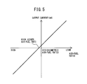
- the thus configured air-fuel ratio sensors 40, 41 have the output characteristic shown in FIG. 5 . That is, in the air-fuel ratio sensors 40, 41, the larger the exhaust air-fuel ratio becomes (that is, the leaner it becomes), the larger the pump current (sensor output current) Ip becomes. In addition, in the present embodiment, the air-fuel ratio sensors 40, 41 are configured so that the pump current (sensor output current) Ip becomes zero when the exhaust air-fuel ratio conforms to the rich judged air-fuel ratio.
- FIG. 6 is a view which schematically shows the operation of the reference cell 61.
- a constant sensor applied voltage Vr is applied across these electrodes 57 and 58 so that the reference side electrode 58 becomes a positive polarity and the gas chamber side electrode 57 becomes a negative polarity.
- movement of oxygen ions occurs from the gas chamber side electrode 57 to the reference side electrode 58 so that the ratio of concentration of oxygen between the two side surfaces of the second solid electrolyte layer 54 becomes larger toward the ratio of concentration of oxygen which corresponds to the sensor applied voltage Vr.
- current flows from the positive electrode of the reference cell voltage application device 70 which applies the sensor applied voltage Vr, through the reference side electrode 58, second solid electrolyte layer 54, and gas chamber side electrode 57, to the negative electrode of the reference cell voltage application device 70.
- the magnitude of the current (reference cell output current) Ir is proportional to the flow rate of oxygen flowing from the exhaust gas through the diffusion regulating layer 63 to the measured gas chamber 51, if setting the sensor applied voltage Vr to a suitable value. Therefore, by detecting the magnitude of this current Ir by the reference cell output current detection device 71, the concentration of oxygen in the measured gas chamber 51 can be learned and, in turn, the air-fuel ratio at the lean region can be learned.
- the unburned gas flows from the exhaust gas through the diffusion regulating layer 63 into the measured gas chamber 51, and therefore even if oxygen is present on the gas chamber side electrode 57, it is removed by reaction with the unburned gas. Therefore, in the measured gas chamber 51, the concentration of oxygen becomes extremely low and, as a result, the ratio of the concentration of oxygen at the two side surfaces of the second solid electrolyte layer 54 becomes large.
- the magnitude of the current (reference cell output current) Ir which flows at this time is determined by the flow rate of oxygen ions which moves through the second solid electrolyte layer 54 from the reference side electrode 58 to the gas chamber side electrode 57.
- the oxygen ions react (burn) on the gas chamber side electrode 57 with the inflowing unburned gas, which flows from the exhaust gas through the diffusion regulating layer 63 and are diffused into the measured gas chamber 51. Accordingly, the flow rate of movement of oxygen ions corresponds to the concentration of unburned gas in the exhaust gas which flows into the measured gas chamber 51. Therefore, by detecting the magnitude of this current Ir by the reference cell output current detection device 71, it is possible to learn the concentration of unburned gas in the measured gas chamber 51 and in turn possible to learn the air-fuel ratio in the rich region.
- the exhaust air-fuel ratio in the measured gas chamber 51 conforms to the rich judged air-fuel ratio
- the amounts of oxygen and unburned gas in the measured gas chamber 51 become a chemical equivalent ratio. Therefore, the catalytic action of the gas chamber side electrode 57 causes the oxygen and unburned gas to completely burn, and no fluctuation occurs in the concentrations of oxygen and unburned gas in the measured gas chamber 51.
- the ratio of concentration of oxygen between the two side surfaces of the second solid electrolyte layer 54 does not fluctuate, but is maintained as the ratio of concentration of oxygen which corresponds to the sensor applied voltage Vr. Therefore, as shown in FIG. 6(C) , no movement of oxygen ions occurs due to the oxygen pump characteristic, and as a result, no current is generated which flows through the circuit.
- FIG. 7 is a view which shows the relationship between the sensor applied voltage Vr in the reference cell and the reference cell output current Ir.
- the reference cell has a limit current region where even if increasing the sensor applied voltage Vr, the reference cell output current Ir does not increase much at all. However, in this limit current region as well, when making the exhaust air-fuel ratio constant, as the sensor applied voltage Vr increases, the reference cell output current Ir also increases - though very slightly. For example, if taking as an example the case where the exhaust air-fuel ratio is the stoichiometric air-fuel ratio (14.6), when the sensor applied voltage Vr is 0.45V or so, the reference cell output current Ir becomes 0.
- the reference cell output current Ir becomes a value lower than 0.
- the reference cell output current Ir becomes a value higher than 0.
- FIG. 8 is a view which shows the relationship between the exhaust air-fuel ratio and the reference cell output current Ir. From FIG. 8 , it is learned that in the region near the stoichiometric air-fuel ratio, the reference cell output current Ir for the same exhaust air-fuel ratio differs slightly for each sensor applied voltage Vr. For example, in the illustrated example, in the case where the exhaust air-fuel ratio is the stoichiometric air-fuel ratio, when the sensor applied voltage Vr is set to 0.45V, the reference cell output current Ir becomes 0. Further, if setting the sensor applied voltage Vr greater than 0.45V, the reference cell output current Ir also becomes larger, while if setting the sensor applied voltage Vr smaller than 0.45V, the reference cell output current Ir becomes smaller.
- the reference cell output current Ir becomes 0 when the exhaust air-fuel ratio is leaner than the stoichiometric air-fuel ratio.
- the rate of change of output current varies among individual specimens of the air-fuel ratio sensor, or variations occur in the same air-fuel ratio sensor due to aging, etc. Further, such a tendency also applies to the reference cell 61.
- the ratio of the amount of increase of the reference cell output current with respect to the amount of increase of the exhaust air-fuel ratio (below, called the "rate of change of reference cell output current") will not necessarily become the same even after going through similar production processes. Variations will occur between specimens even for the same type of air-fuel ratio sensor. In addition, even in the same air-fuel ratio sensor, the rate of change of reference cell output current changes due to aging, etc.
- the exhaust air-fuel ratio at the time of zero current in the example of FIG. 2 , the stoichiometric air-fuel ratio
- the absolute value of the exhaust air-fuel ratio at that time will not necessarily be constant.
- the absolute value of the exhaust air-fuel ratio at that time in the example of FIG. 17 , the stoichiometric air-fuel ratio
- the air-fuel ratio sensors 40, 41 it is possible to change the exhaust air-fuel ratio at the time of zero current by changing the sensor applied voltage Vr. Further, if the reference cell output current detected by the reference cell output current detection device 71 is zero, the pump voltage applied by the pump voltage application device 72 is also made zero, and the pump current (sensor output current) Ip also becomes zero. Therefore, according to the air-fuel ratio sensors 40, 41, by changing the sensor applied voltage Vr change, it is possible to accurately detect the absolute value of the exhaust air-fuel ratio other than the stoichiometric air-fuel ratio.
- the sensor applied voltage Vr As explained above, by changing the sensor applied voltage Vr, it is possible to change the exhaust air-fuel ratio at the time of zero current. However, if changing the sensor applied voltage Vr so as to be larger than a certain upper limit voltage or smaller than a certain lower limit voltage, the amount of change in the exhaust air-fuel ratio at the time of zero current, with respect to the amount of change in the sensor applied voltage Vr, becomes larger. Therefore, in these voltage regions, if the sensor applied voltage Vr slightly shifts, the exhaust air-fuel ratio at the time of zero current greatly changes. Therefore, in this voltage region, to accurately detect the absolute value of the exhaust air-fuel ratio, it becomes necessary to precisely control the sensor applied voltage Vr. This is not that practical. Therefore, from the viewpoint of accurately detecting the absolute value of the exhaust air-fuel ratio, the sensor applied voltage Vr has to be a value within a "specific voltage region" between a certain upper limit voltage and a certain lower limit voltage.
- This specific voltage region can be defined by various methods. Below, FIG. 9 to FIG. 12 will be used to explain an example of several definitions.
- the reference cell 61 have a current increase region which is a voltage region where the reference cell output current Ir increases along with an increase of the sensor applied voltage Vr for each exhaust air-fuel ratio, and a current fine increase region which is a voltage region where the amount of increase of the reference cell output current Ir with respect the amount of increase of the sensor applied voltage Vr becomes smaller than that in the current increase region, due to the provision of the diffusion regulating layer (in FIG. 9(A) , current increase region and current fine increase region are shown only for when the exhaust air-fuel ratio is the stoichiometric air-fuel ratio).
- the current fine increase region of when the exhaust air-fuel ratio is the stoichiometric air-fuel ratio is defined as the "specific voltage region".
- the reference cell 61 has a limit current region which is a voltage region where the reference cell output current Ir becomes a limit current for each exhaust air-fuel ratio (in FIG. 9(B) , limit current region is shown only for when the exhaust air-fuel ratio is the stoichiometric air-fuel ratio).
- the limit current region when the exhaust air-fuel ratio is the stoichiometric air-fuel ratio is defined as the "specific voltage region”.
- the air-fuel ratio sensors 40, 41 have a proportional region which is a voltage region where the reference cell output current Ir increases in proportion to an increase in the applied voltage for each exhaust air-fuel ratio, a moisture breakdown region which is a voltage region where the reference cell output current Ir changes in accordance with a change in the applied voltage due to breakdown of water and the solid electrolyte layer 51, and an intermediate region which is a voltage region between these proportional region and moisture breakdown region (in FIG. 9(C) , proportional region, moisture breakdown region, and intermediate region shown only for when the exhaust air-fuel ratio is the stoichiometric air-fuel ratio).
- the intermediate region where the exhaust air-fuel ratio is the stoichiometric air-fuel ratio is defined as a "specific voltage region".
- the exhaust air-fuel ratio at the time of zero current changes in accordance with the sensor applied voltage Vr.
- the exhaust air-fuel ratio at the time of zero current becomes an air-fuel ratio which is for example 0.5 to 2% or so (preferably 1% or so) lower than the stoichiometric air-fuel ratio AFst.
- the exhaust air-fuel ratio at the time of zero current becomes an air-fuel ratio which is for example 0.5 to 2% or so (preferably 1% or so) higher than the stoichiometric air-fuel ratio AFst.
- the voltage region between the upper limit voltage value (voltage value where exhaust air-fuel ratio at the time of zero current becomes an air-fuel ratio lower by for example 1% from the stoichiometric air-fuel ratio AFst) and the lower limit voltage value (voltage value where exhaust air-fuel ratio at the time of zero current becomes an air-fuel ratio higher by for example 1% from the stoichiometric air-fuel ratio AFst) is defined as the "specific voltage region".
- FIG. 11 shows a change in current with respect to the voltage.
- the reference cell output current Ir increases until the first curved point B 1 as the sensor applied voltage Vr increases from the negative state
- the reference cell output current Ir increases until the second curved point B 2 as the sensor applied voltage Vr increases from the first curved point B 1
- the reference cell output current Ir increases as the sensor applied voltage Vr increases from the second curved point.
- the amount of increase of the applied current Ir with respect to the amount of increase of the sensor applied voltage Vr is smaller than in the other voltage regions.
- the voltage between the first curved point and second curved point when the first exhaust air-fuel ratio is the stoichiometric air-fuel ratio is defined as the "specific voltage region”.
- the upper limit voltage value and the lower limit voltage value of the "specific voltage region" are specified by specific numerical values.
- the "specific voltage region” is 0.05V to 0.95V, preferably 0.1V to 0.9V, more preferably 0.15V to 0.8V.
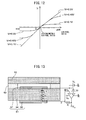
- FIG. 12 is a view, similar to FIG. 8 , which shows the relationship between the exhaust air-fuel ratio and reference cell output current Ir, at the different sensor applied voltages Vr.
- FIG. 8 shows the relationship only near the stoichiometric air-fuel ratio in a microscopic manner
- FIG. 12 shows the relationship for a broader range of air-fuel ratio in a macroscopic manner.
- the reference cell output current Ir will no longer become 0 (for example, when the sensor applied voltage Vr is set to 0V, regardless of the exhaust air-fuel ratio, the reference cell output current Ir will not become 0).
- the sensor applied voltage Vr is a voltage between the maximum voltage and the minimum voltage, there is an exhaust air-fuel ratio where the reference cell output current becomes zero. Conversely, if the sensor applied voltage Vr is a voltage higher than the maximum voltage or a voltage lower than the minimum voltage, there is no exhaust air-fuel ratio where the reference cell output current will become zero. Therefore, the sensor applied voltage Vr at least has to be a voltage where the reference cell output current becomes zero when the exhaust air-fuel ratio is any air-fuel ratio, that is, a voltage between the maximum voltage and the minimum voltage.
- the above-mentioned "specific voltage region” is the voltage region between the maximum voltage and the minimum voltage.
- the sensor applied voltage Vrup at the upstream side air-fuel ratio sensor 40 is fixed to a constant voltage (for example, 0.45V) where the reference cell output current (and, sensor output current) becomes zero when the exhaust air-fuel ratio is the stoichiometric air-fuel ratio (in the present embodiment, 14.6).
- the sensor applied voltage Vrup is set so that the exhaust air-fuel ratio at the time of zero current becomes the stoichiometric air-fuel ratio.
- the sensor applied voltage Vr at the downstream side air-fuel ratio sensor 41 is fixed to a constant voltage (for example, 0.7V) where the reference cell output current (and, sensor output current) becomes zero when the exhaust air-fuel ratio is a predetermined rich judged air-fuel ratio slightly richer than the stoichiometric air-fuel ratio (for example, 14.55).
- the sensor applied voltage Vrdwn is set so that exhaust air-fuel ratio at the time of zero current becomes a rich judged air-fuel ratio which is slightly richer than the stoichiometric air-fuel ratio.
- the sensor applied voltage Vrdwn of the downstream side air-fuel ratio sensor 41 is higher voltage than the sensor applied voltage Vrup of the upstream side air-fuel ratio sensor 40.
- the ECU 31 connected to the two air-fuel ratio sensors 40, 41 judges that the exhaust air-fuel ratio around the upstream side air-fuel ratio sensor 40 is the stoichiometric air-fuel ratio when the sensor output current Ipup of the upstream side air-fuel ratio sensor 40 becomes zero.
- the ECU 31 judges that the exhaust air-fuel ratio around the downstream side air-fuel ratio sensor 41 is the lean judged air-fuel ratio, that is, is a predetermined air-fuel ratio leaner than the stoichiometric air-fuel ratio, when the sensor output current Ipdwn of the downstream side air-fuel ratio sensor 41 becomes zero.
- the time of detecting the air-fuel ratio of the exhaust gas by the air-fuel ratio sensor 40 for example, when a fuel cut control explained below is not performed, or when the air-fuel ratio detected by the air-fuel ratio sensor is not high value of 18 or higher, may be mentioned.
- FIG. 13 shows an example of the specific circuits which form the reference cell voltage application device 70 and reference cell current detection device 71.
- the electromotive force E which occurs due to the oxygen cell characteristic is expressed as "E”
- the internal resistance of the second solid electrolyte layer 54 is expressed as "Ri”
- the difference of electrical potential across the two electrodes 57, 58 is expressed as "Vs”.
- the reference cell voltage application device 70 basically performs negative feedback control so that the electromotive force E which occurs due to the oxygen cell characteristic matches the sensor applied voltage Vr. In other words, the reference cell voltage application device 70 performs negative feedback control so that even when a change in the oxygen concentration ratio between the two side surfaces of the second solid electrode layer 54 causes the potential difference Vs between the two electrodes 57 and 58 to change, this potential difference Vs becomes the sensor applied voltage Vr.
- the exhaust air-fuel ratio in the measured gas chamber 51 becomes the stoichiometric air-fuel ratio and no change occurs in the oxygen concentration ratio between the two side surfaces of the second solid electrolyte layer 54
- the oxygen concentration ratio between the two side surfaces of the second solid electrolyte layer 54 becomes the oxygen concentration ratio corresponding to the sensor applied voltage Vr.
- the electromotive force E conforms to the sensor applied voltage Vr
- the potential difference Vs between the two electrodes 57 and 58 also becomes the sensor applied voltage Vr, and, as a result, the current Ir does not flow.
- the exhaust air-fuel ratio becomes an air-fuel ratio which is different from the stoichiometric air-fuel ratio and a change occurs in the oxygen concentration ratio between the two side surfaces of the second solid electrolyte layer 54
- the oxygen concentration ratio between the two side surfaces of the second solid electrolyte layer 54 does not become an oxygen concentration ratio corresponding to the sensor applied voltage Vr.
- the electromotive force E becomes a value different from the sensor applied voltage Vr. Therefore, due to negative feedback control, a potential difference Vs is applied between the two electrodes 57 and 58 so that oxygen ions move between the two side surfaces of the second solid electrolyte layer 54 so that the electromotive force E conforms to the sensor applied voltage Vr.
- the reference cell voltage application device 70 can be said to substantially apply the sensor applied voltage Vr between the two electrodes 57 and 58.
- the electrical circuit of the reference cell voltage application device 70 does not have to be one such as shown in FIG. 13 .
- the circuit may be any form of device so long as able to substantially apply the sensor applied voltage Vr across the two electrodes 57, 58.
- the reference cell current detection device 71 does not actually detect the current. It detects the voltage E 0 to calculate the current from this voltage E 0 .
- E 0 is expressed as in the following equation (1).
- E 0 Vr + V 0 + I r ⁇ R
- V 0 is the offset voltage (voltage applied so that E 0 does not become a negative value, for example, 3V)
- R is the value of the resistance shown in FIG. 13 .
- the sensor applied voltage Vr, offset voltage V 0 , and resistance value R are constant, and therefore the voltage E 0 changes in accordance with the current Ir. For this reason, if detecting the voltage E 0 , it is possible to calculate the current Ir from that voltage E 0 .
- the reference cell current detection device 71 can be said to substantially detect the current Ir which flows across the two electrodes 57, 58. Note that, the electrical circuit of the reference cell current detection device 71 does not have to be one such as shown in FIG. 13 . If possible to detect the current Ir flowing across the two electrodes 57, 58, any form of device may be used.
- the upstream side exhaust purification catalyst 20 is a three-way catalyst which has an oxygen storage ability.
- the upstream side exhaust purification catalyst 20 is comprised of a carrier made of ceramic on which a precious metal which has a catalytic action (for example, platinum (Pt)) and a substance which has an oxygen storage ability (for example, ceria (CeO 2 )) are carried. If the upstream side exhaust purification catalyst 20 reaches a predetermined activation temperature, it exhibits an oxygen storage ability in addition to the catalytic action of simultaneously removing the unburned gas (HC, CO, etc.) and nitrogen oxides (NO X ).
- the upstream side exhaust purification catalyst 20 stores the oxygen in the exhaust gas, when the air-fuel ratio of the exhaust gas flowing into the upstream side exhaust purification catalyst 20 is leaner than the stoichiometric air-fuel ratio (lean air-fuel ratio).
- the upstream side exhaust purification catalyst 20 releases the oxygen which is stored in the upstream side exhaust purification catalyst 20 when the air-fuel ratio of the inflowing exhaust gas is richer than the stoichiometric air-fuel ratio (rich air-fuel ratio).
- the "air-fuel ratio of the exhaust gas” means the ratio of the mass of the fuel to the mass of the air which are fed up to when the exhaust gas is produced. Usually, it means the ratio of the mass of the fuel to the mass of the air which are fed into the combustion chamber 5 when that exhaust gas is produced.
- the upstream side exhaust purification catalyst 20 has a catalytic action and an oxygen storage ability, and therefore has the action of removing NO X and unburned gas in accordance with the oxygen storage amount.
- FIG. 14 shows the relationship between the oxygen storage amount of the upstream side exhaust purification catalyst 20 and the concentration of NO X and unburned gas (HC, CO, etc.) which flow out from the upstream side exhaust purification catalyst 20.
- FIG. 14(A) shows the relationship between the oxygen storage amount and the concentration of NO X in the exhaust gas flowing out from the upstream side exhaust purification catalyst 20, when the air-fuel ratio of the exhaust gas flowing into the upstream side exhaust purification catalyst 20 is a lean air-fuel ratio.
- FIG. 14 shows the relationship between the oxygen storage amount of the upstream side exhaust purification catalyst 20 and the concentration of NO X in the exhaust gas flowing out from the upstream side exhaust purification catalyst 20, when the air-fuel ratio of the exhaust gas flowing into the upstream side exhaust purification catalyst 20 is a lean air-fuel ratio.
- 14(B) shows the relationship between the oxygen storage amount and the concentration of unburned gas in the exhaust gas flowing out from the upstream side exhaust purification catalyst 20, when the air-fuel ratio of the exhaust gas flowing into the upstream side exhaust purification catalyst 20 is a rich air-fuel ratio.
- the oxygen storage amount of the upstream side exhaust purification catalyst 20 increases, when the air-fuel ratio of the exhaust gas flowing into the upstream side exhaust purification catalyst 20 is a lean air-fuel ratio, it becomes difficult for the upstream side exhaust purification catalyst 20 to store the oxygen in the exhaust gas. Along with this, the NO X in the exhaust gas also becomes harder to be reduced and purified. For this reason, as will be understood from FIG. 14(A) , if the oxygen storage amount increases over a certain upper limit storage amount Cuplim, the concentration of NO X in the exhaust gas flowing out from the upstream side exhaust purification catalyst 20 rapidly rises.
- the oxygen storage amount of the upstream side exhaust purification catalyst 20 is large, if the air-fuel ratio of the exhaust gas flowing into the upstream side exhaust purification catalyst 20 is the rich air-fuel ratio (that is, this exhaust gas contains unburned gas, such as HC or CO), oxygen stored in the upstream side exhaust purification catalyst 20 is released. For this reason, the unburned gas in the exhaust gas flowing into the upstream side exhaust purification catalyst 20 is oxidized and purified. As a result, as will be understood from FIG. 14(B) , the exhaust gas flowing out from the upstream side exhaust purification catalyst 20 does not contain almost any unburned gas.
- the oxygen storage amount of the upstream side exhaust purification catalyst 20 becomes smaller, when the air-fuel ratio of the exhaust gas flowing into the upstream side exhaust purification catalyst 20 is the rich air-fuel ratio, the oxygen released from the upstream side exhaust purification catalyst 20 becomes smaller. Along with this, the unburned gas in the exhaust gas flowing into the upstream side exhaust purification catalyst 20 also becomes harder to be oxidized and purified. For this reason, as will be understood from FIG. 14(B) , if the oxygen storage amount decreases beyond a certain lower limit storage amount Clowlim, the concentration of unburned gas in the exhaust gas flowing out from the upstream side exhaust purification catalyst 20 rapidly rises.
- the characteristic of purification of NO X and unburned gas in the exhaust gas changes in accordance with the air-fuel ratio of the exhaust gas flowing into the exhaust purification catalysts 20, 24 and oxygen storage amount.
- the exhaust purification catalysts 20, 24 may also be catalysts which are different from three-way catalysts.
- the target air-fuel ratio of the exhaust gas flowing into the upstream side exhaust purification catalyst 20 is set based on the sensor output current Ipdwn of the downstream side air-fuel ratio sensor 41. Specifically, the target air-fuel ratio is set to the lean set air-fuel ratio when the sensor output current Ipdwn of the downstream side air-fuel ratio sensor 41 becomes zero or less and is maintained at that air-fuel ratio.
- the fact that the sensor output current Ipdwn becomes zero or less means that the air-fuel ratio of the exhaust gas flowing out from the upstream side exhaust purification catalyst 20 becomes a predetermined rich judged air-fuel ratio (for example, 14.55), which is slightly richer than the stoichiometric air-fuel ratio, or less.
- the lean set air-fuel ratio is a predetermined air-fuel ratio leaner than the stoichiometric air-fuel ratio by a certain extent. For example, it is 14.65 to 20, preferably 14.68 to 18, more preferably 14.7 to 16 or so.
- the oxygen storage amount OSAsc of the upstream side exhaust purification catalyst 20 is estimated.
- the oxygen storage amount OSAsc is estimated based on the sensor output current Ipup of the upstream side air-fuel ratio sensor 40, and the estimated value of the amount of intake air to the combustion chamber 5, which is calculated based on the air flow meter 39, etc., or the amount of fuel injection from the fuel injector 11, etc. Further, if the estimated value of the oxygen storage amount OSAsc becomes a predetermined judged reference storage amount Cref or more, the target air-fuel ratio which was the lean set air-fuel ratio up to then is changed to a weak rich set air-fuel ratio and is maintained at that air-fuel ratio.
- the weak rich set air-fuel ratio is a predetermined air-fuel ratio slightly richer than the stoichiometric air-fuel ratio. For example, it is 13.5 to 14.58, preferably 14 to 14.57, more preferably 14.3 to 14.55 or so. After that, when the sensor output current Ipdwn of the downstream side air-fuel ratio sensor 41 again becomes zero or less, the target air-fuel ratio is again set to the lean set air-fuel ratio, and then a similar operation is repeated.
- the target air-fuel ratio of the exhaust gas flowing into the upstream side exhaust purification catalyst 20 is alternately set to the lean set air-fuel ratio and the weak rich set air-fuel ratio.
- the difference between the lean set air-fuel ratio and the stoichiometric air-fuel ratio is larger than the difference between the weak rich set air-fuel ratio and the stoichiometric air-fuel ratio. Therefore, in the present embodiment, the target air-fuel ratio is alternately set to lean set air-fuel ratio for a short period of time and weak rich set air-fuel ratio for a long period of time.
- FIG. 15 is a time chart of the oxygen storage amount OSAsc of the upstream side exhaust purification catalyst 20, the sensor output current Ipdwn of the downstream side air-fuel ratio sensor 41, the sensor output current Ipup of the upstream side air-fuel ratio sensor 40 and NOx concentration in the exhaust gas flowing out from the upstream side exhaust purification catalyst 20, in the case of performing air-fuel ratio control in a control system of an internal combustion engine of the present invention.
- the sensor output current Ipup of the upstream side air-fuel ratio sensor 40 becomes zero when the air-fuel ratio of the exhaust gas flowing into the upstream side exhaust purification catalyst 20 is the stoichiometric air-fuel ratio, becomes a negative value when the air-fuel ratio of the exhaust gas is a rich air-fuel ratio, and becomes a positive value when the air-fuel ratio of the exhaust gas is a lean air-fuel ratio.
- the air-fuel ratio of the exhaust gas flowing into the upstream side exhaust purification catalyst 20 is a rich air-fuel ratio or lean air-fuel ratio
- the greater the difference from the stoichiometric air-fuel ratio the larger the absolute value of the sensor output current Ipup of the upstream side air-fuel ratio sensor 40.
- the sensor output current Ipdwn of the downstream side air-fuel ratio sensor 41 becomes zero when the air-fuel ratio of the exhaust gas flowing out from the upstream side exhaust purification catalyst 20 is the rich judged air-fuel ratio (slightly richer than stoichiometric air-fuel ratio), becomes a negative value when the air-fuel ratio of the exhaust gas is richer than the rich judged air-fuel ratio and becomes a positive value when the air-fuel ratio of the exhaust gas is leaner than the rich judged air-fuel ratio.
- the air-fuel ratio of the exhaust gas flowing out from the upstream side exhaust purification catalyst 20 is richer or leaner than the rich judged air-fuel ratio
- the larger the difference from the rich judged air-fuel ratio the larger the absolute value of the sensor output current Ipdwn of the downstream side air-fuel ratio sensor 41.
- the air-fuel ratio shift amount AFC is a shift amount relating to the target air-fuel ratio.
- the target air-fuel ratio is the stoichiometric air-fuel ratio
- the air-fuel ratio shift amount AFC is a positive value
- the target air-fuel ratio becomes a lean air-fuel ratio
- the air-fuel ratio shift amount AFC is a negative value
- the target air-fuel ratio becomes a rich air-fuel ratio.
- the air-fuel ratio shift amount AFC is set to the weak rich set shift amount AFCrich.
- the weak rich set shift amount AFCrich is a value corresponding to the weak rich set air-fuel ratio and a value smaller than 0. Therefore, the target air-fuel ratio is set to a rich air-fuel ratio.
- the sensor output current Ipup of the upstream side air-fuel ratio sensor 40 becomes a negative value.
- the exhaust gas flowing into the upstream side exhaust purification catalyst 20 contains unburned gas, and therefore the oxygen storage amount OSAsc of the upstream side exhaust purification catalyst 20 gradually decreases.
- the unburned gas contained in the exhaust gas is purified at the upstream side exhaust purification catalyst 20, and therefore the air-fuel ratio of the exhaust gas flowing out from the upstream side exhaust purification catalyst 20 becomes substantially the stoichiometric air-fuel ratio.
- the sensor output current Ipdwn of the downstream side air-fuel ratio sensor becomes a positive value (corresponding to stoichiometric air-fuel ratio).
- the air-fuel ratio of the exhaust gas flowing into the upstream side exhaust purification catalyst 20 becomes a rich air-fuel ratio, and therefore the amount of NO X exhausted from the upstream side exhaust purification catalyst 20 is suppressed.
- the oxygen storage amount OSAsc of the upstream side exhaust purification catalyst 20 gradually decreases, the oxygen storage amount OSAsc decreases to less than the lower limit storage amount (see Clowlim of FIG. 14 ) at the time t 1 . If the oxygen storage amount OSAsc decreases to less than the lower limit storage amount, part of the unburned gas flowing into the upstream side exhaust purification catalyst 20 flows out without being purified at the upstream side exhaust purification catalyst 20. For this reason, after the time t 1 , the sensor output current Ipdwn of the downstream side air-fuel ratio sensor 41 gradually falls along with the decrease in the oxygen storage amount OSAsc of the upstream side exhaust purification catalyst 20. At this time as well, the air-fuel ratio of the exhaust gas flowing into the upstream side exhaust purification catalyst 20 becomes a rich air-fuel ratio, and therefore the amount of NO X exhausted from the upstream side exhaust purification catalyst 20 is suppressed.
- the sensor output current Ipdwn of the downstream side air-fuel ratio sensor 41 reaches zero corresponding to the rich judged air-fuel ratio.
- the air-fuel ratio shift amount AFC is switched to the lean set shift amount AFClean so as to suppress the decrease of the oxygen storage amount OSAsc of the upstream side exhaust purification catalyst 20.
- the lean set shift amount AFClean is a value corresponding to the lean set air-fuel ratio and is a value larger than 0. Therefore, the target air-fuel ratio is set to a lean air-fuel ratio.
- the air-fuel ratio shift amount AFC is switched after the sensor output current Ipdwn of the downstream side air-fuel ratio sensor 41 reaches zero, that is, after the air-fuel ratio of the exhaust gas flowing out from the upstream side exhaust purification catalyst 20 reaches the rich judged air-fuel ratio. This is because even if the oxygen storage amount of the upstream side exhaust purification catalyst 20 is sufficient, the air-fuel ratio of the exhaust gas flowing out from the upstream side exhaust purification catalyst 20 sometimes deviates slightly from the stoichiometric air-fuel ratio.
- the oxygen storage amount decreases to lower than the lower limit storage amount. Therefore, in the present embodiment, it is judged the oxygen storage amount decreases lower than the lower limit storage amount, only when the air-fuel ratio of the exhaust gas flowing out from the upstream side exhaust purification catalyst 20 reaches the rich judged air-fuel ratio.
- the rich judged air-fuel ratio is set to an air-fuel ratio which the air-fuel ratio of the exhaust gas flowing out from the upstream side exhaust purification catalyst 20 does not reach much at all when the oxygen storage amount of the upstream side exhaust purification catalyst 20 is sufficient.
- the air-fuel ratio of the exhaust gas flowing into the upstream side exhaust purification catalyst 20 does not immediately become the lean air-fuel ratio, and a certain extent of delay arises.
- the air-fuel ratio of the exhaust gas flowing into the upstream side exhaust purification catalyst 20 changes from the rich air-fuel ratio to the lean air-fuel ratio at the time t 3 .
- the air-fuel ratio of the exhaust gas flowing out from the upstream side exhaust purification catalyst 20 is a rich air-fuel ratio, and therefore this exhaust gas contains unburned gas.
- the amount of discharge of NO X from the upstream side exhaust purification catalyst 20 is suppressed.
- the oxygen storage amount OSAsc of the upstream side exhaust purification catalyst 20 increases. Further, along with this, the air-fuel ratio of the exhaust gas flowing out from the upstream side exhaust purification catalyst 20 changes to the stoichiometric air-fuel ratio, and the sensor output current Ipdwn of the downstream side air-fuel ratio sensor 41 also converges to a positive value corresponding to the stoichiometric air-fuel ratio.
- the upstream side exhaust purification catalyst 20 has sufficient leeway in the oxygen storage ability, and therefore the oxygen in the inflowing exhaust gas is stored in the upstream side exhaust purification catalyst 20 and the NO X is reduced and purified. For this reason, the amount of NO X exhausted from the upstream side exhaust purification catalyst 20 is suppressed.
- the oxygen storage amount OSAsc of the upstream side exhaust purification catalyst 20 increases, at the time t 4 , the oxygen storage amount OSAsc reaches the judged reference storage amount Cref.
- the air-fuel ratio shift amount AFC is switched to a weak rich set shift amount AFCrich (value smaller than 0) to stop the storage of oxygen in the upstream side exhaust purification catalyst 20. Therefore, the target air-fuel ratio is set to the rich air-fuel ratio.
- the judged reference storage amount Cref is set sufficiently lower than the maximum oxygen storage amount Cmax or the upper limit storage amount (see Cuplim in FIG. 14 ), and therefore even at the time t 5 , the oxygen storage amount OSAsc does not reach the maximum oxygen storage amount Cmax or the upper limit storage amount.
- the judged reference storage amount Cref is set to an amount sufficiently small so that the oxygen storage amount OSAsc does not reach the maximum oxygen storage amount Cmax or the upper limit storage amount even if a delay occurs from when switching the target air-fuel ratio to when the air-fuel ratio of the exhaust gas flowing into the upstream side exhaust purification catalyst 20 actually changes.
- the judged reference storage amount Cref is set to 3/4 or less of the maximum oxygen storage amount Cmax, preferably 1/2 or less, more preferably 1/5 or less. Therefore, during times t 4 to t 5 as well, the amount of NO X exhausted from the upstream side exhaust purification catalyst 20 is suppressed.
- the air-fuel ratio shift amount AFC is set to the weak rich set shift amount AFCrich. Therefore, the target air-fuel ratio is set to the rich air-fuel ratio.
- the sensor output current Ipup of the upstream side air-fuel ratio sensor 40 becomes a negative value.
- the exhaust gas flowing into the upstream side exhaust purification catalyst 20 contains unburned gas, and therefore the oxygen storage amount OSAsc of the upstream side exhaust purification catalyst 20 gradually decreases.
- the oxygen storage amount OSAsc decreases below the lower limit storage amount.
- the air-fuel ratio of the exhaust gas flowing into the upstream side exhaust purification catalyst 20 becomes a rich air-fuel ratio, and therefore the amount of NO X exhausted from the upstream side exhaust purification catalyst 20 is suppressed.
- the sensor output current Ipdwn of the downstream side air-fuel ratio sensor 41 reaches zero corresponding to the rich judged air-fuel ratio. Due to this, the air-fuel ratio shift amount AFC is switched to the value AFClean corresponding to the lean set air-fuel ratio. Then, the cycle of the above-mentioned times t 1 to t 6 is repeated. Note that, during these cycles, the applied voltage Vrdwn to the downstream side air-fuel ratio sensor 41 is maintained at a voltage whereby the exhaust air-fuel ratio at the time of zero current becomes the rich judged air-fuel ratio.
- the ECU 31 can be said to comprise: an oxygen storage amount increasing means for continuously setting a target air-fuel ratio of exhaust gas flowing into the upstream side catalyst 20 a lean set air-fuel ratio when the air-fuel ratio of the exhaust gas which was detected by the downstream side air-fuel ratio sensor 41 becomes a rich judged air-fuel ratio or less, until the oxygen storage amount OSAsc of the upstream side catalyst 20 becomes the judged reference storage amount Cref; and an oxygen storage amount decreasing means for continuously setting the target air-fuel ratio a weak rich set air-fuel ratio when the oxygen storage amount OSAsc of the upstream side catalyst 20 becomes the judged reference storage amount Cref or more so that the oxygen storage amount OSAsc never exceeds the maximum oxygen storage amount Cmax but decreases toward zero.
- the oxygen storage amount OSAsc is estimated based on the sensor output current Ipup of the upstream side air-fuel ratio sensor 40 and the estimated value of the intake air amount, etc., there is the possibility that error will occur.
- the oxygen storage amount OSAsc is estimated over the times t 3 to t 4 , and therefore the estimated value of the oxygen storage amount OSAsc includes some error.
- the judged reference storage amount Cref sufficiently lower than the maximum oxygen storage amount Cmax or upper limit storage amount, the actual oxygen storage amount OSAsc will almost never reach the maximum oxygen storage amount Cmax or upper limit storage amount. Therefore, from such a viewpoint as well, it is possible to suppress the amount of discharge of NO X from the upstream side exhaust purification catalyst 20.
- the oxygen storage amount OSAsc constantly fluctuates up and down, so the oxygen storage ability is kept from falling.
- the downstream side air-fuel ratio sensor 41 can accurately detect the absolute value at the rich judged air-fuel ratio.
- FIG. 2 in a conventional air-fuel ratio sensor, it was difficult to accurately detect the absolute value for an air-fuel ratio other than the stoichiometric air-fuel ratio.
- the sensor output current of the air-fuel ratio sensor may be a value which corresponds to the rich judged air-fuel ratio.
- the downstream side air-fuel ratio sensor 41 can accurately detect the absolute value at the rich judged air-fuel ratio. For this reason, it is possible to keep the timing of switching of the air-fuel ratio shift amount AFC from the weak rich set shift amount AFCrich to the lean set shift amount AFClean, from becoming delayed or such switching from being performed at a timing not requiring such switching.
- the air-fuel ratio shift amount AFC is maintained at the lean set shift amount AFClean.
- the air-fuel ratio shift amount AFC does not necessarily have to be maintained constant. It may be set to gradually decrease or otherwise change.
- the air-fuel ratio shift amount AFC is maintained at the weak rich set shift amount AFrich.
- the air-fuel ratio shift amount AFC does not necessarily have to be maintained constant. It may be set to gradually decrease or otherwise change.
- the air-fuel ratio shift amount AFC during the times t 2 to t 4 is set so that the difference of the average value of the target air-fuel ratio and the stoichiometric air-fuel ratio in that period becomes larger than the difference between the average value of the target air-fuel ratio and the stoichiometric air-fuel ratio during the times t 4 to t 7 .
- the oxygen storage amount OSAsc of the upstream side exhaust purification catalyst 20 is estimated, based on the sensor output current Ipup of the upstream side air-fuel ratio sensor 40 and the estimated value of the amount of intake air to the combustion chamber 5, etc.
- the oxygen storage amount OSAsc may also be calculated by other parameters in addition to these parameters and may be estimated based on parameters which are different from these parameters. Further, in the above embodiment, if the estimated value of the oxygen storage amount OSAsc becomes the judged reference storage amount Cref or more, the target air-fuel ratio is switched from the lean set air-fuel ratio to the weak rich set air-fuel ratio.
- the timing of switching the target air-fuel ratio from the lean set air-fuel ratio to the weak rich set air-fuel ratio may, for example, use as a reference other parameter, such as the engine operating time etc. from when switching the target air-fuel ratio from the weak rich set air-fuel ratio to the lean set air-fuel ratio.
- the target air-fuel ratio has to be switched from the lean set air-fuel ratio to the weak rich set air-fuel ratio in the period when the oxygen storage amount OSAsc of the upstream side exhaust purification catalyst 20 is estimated to be smaller than the maximum oxygen storage amount.
- a downstream side exhaust purification catalyst 24 is provided in addition to the upstream side exhaust purification catalyst 20, a downstream side exhaust purification catalyst 24 is provided.
- the oxygen storage amount OSAvemc of the downstream side exhaust purification catalyst 24 becomes a value near the maximum storage amount Cmax by fuel cut control which is performed every certain extent of time period. For this reason, even if exhaust gas containing unburned gas flows out from the upstream side exhaust purification catalyst 20, the unburned gas is oxidized and purified at the downstream side exhaust purification catalyst 24.
- fuel cut control is control to prevent injection of fuel from the fuel injectors 11 even if the crankshaft or pistons 3 are in an operating state, at the time of deceleration, etc., of the vehicle which mounts the internal combustion engine. If performing this control, a large amount of air flows into the two catalysts 20, 24.
- FIG. 16 is a view similar to FIG. 15 and shows, instead of the trend in the concentration of NO X of FIG. 15 , the trends in the oxygen storage amount OSAvemc of the downstream side exhaust purification catalyst 24 and the concentration of unburned gas (HC, CO, etc.) in the exhaust gas flowing out from the downstream side exhaust purification catalyst 24. Further, in the example shown in FIG. 16 , control the same as the example shown in FIG. 15 is performed.
- fuel cut control is performed before the time t 1 .
- the oxygen storage amount OSAvemc of the downstream side exhaust purification catalyst 24 is a value close to the maximum oxygen storage amount Cmax.
- the air-fuel ratio of the exhaust gas flowing out from the upstream side exhaust purification catalyst 20 is held at substantially the stoichiometric air-fuel ratio. For this reason, the oxygen storage amount OSAvemc of the downstream side exhaust purification catalyst 24 is maintained constant.
- the downstream side exhaust purification catalyst 24 stores a large amount of oxygen, if the exhaust gas flowing into the downstream side exhaust purification catalyst 24 contains unburned gas, the unburned gas is oxidized and purified by the stored oxygen. Further, along with this, the oxygen storage amount OSAvemc of the downstream side exhaust purification catalyst 24 decreases. However, during the times t 1 to t 4 , the unburned gas flowing out from the upstream side exhaust purification catalyst 20 is not that large, and therefore the amount of decrease of the oxygen storage amount OSconomc in this interval is slight. Therefore, the unburned gas flowing out from the upstream side exhaust purification catalyst 20 during the times t 1 to t 4 is completely reduced and purified at the downstream side exhaust purification catalyst 24.
- control system in the above embodiment is configured including the functional blocks A1 to A9. Below, each functional block will be explained while referring to FIG. 17 .
- the cylinder intake air calculating means A1 basic fuel injection calculating means A2, and fuel injection calculating means A3 are used.
- the cylinder intake air calculating means A1 calculates the intake air amount Mc to each cylinder based on the intake air flow rate Ga measured by the air flow meter 39, the engine speed NE calculated based on the output of the crank angle sensor 44, and the map or calculation formula stored in the ROM 34 of the ECU 31.
- the fuel injector 11 is commanded to inject fuel so that the fuel of the fuel injection amount Qi which was calculated in this way is injected.
- an oxygen storage amount calculating means A4 target air-fuel ratio shift amount calculating means A5, and target air-fuel ratio setting means A6 are used.
- the oxygen storage amount calculating means A4 calculates the estimated value OSAest of the oxygen storage amount of the upstream side exhaust purification catalyst 20, based on the fuel injection amount Qi calculated by the fuel injection calculating means A3 and the sensor output current Ipup of the upstream side air-fuel ratio sensor 40. For example, the oxygen storage amount calculating means A4 multiplies the difference between the air-fuel ratio corresponding to the sensor output current Ipup of the upstream side air-fuel ratio sensor 40 and the stoichiometric air-fuel ratio, with the fuel injection amount Qi, and cumulatively adds the calculated values to calculate the estimated value OSAest of the oxygen storage amount. Note that, the oxygen storage amount calculating means A4 need not constantly estimate the oxygen storage amount of the upstream side exhaust purification catalyst 20.
- the air-fuel ratio shift amount AFC of the target air-fuel ratio is calculated, based on the estimated value OSAest of the oxygen storage amount calculated by the oxygen storage amount calculating means A4 and the sensor output current Ipdwn of the downstream side air-fuel ratio sensor 41.
- the air-fuel ratio shift amount AFC is set to the lean set shift amount AFClean when the sensor output current Ipdwn of the downstream side air-fuel ratio sensor 41 becomes zero (value corresponding to rich judged air-fuel ratio) or less. Then, the air-fuel ratio shift amount AFC is maintained at the lean set shift amount AFClean until the estimated value OSAest of the oxygen storage amount reaches the judged reference storage amount Cref.
- the air-fuel ratio shift amount AFC is set to the weak rich set shift amount AFCrich. After that, the air-fuel ratio shift amount AFC is maintained at a weak rich set shift amount AFCrich until the sensor output current Ipdwn of the downstream side air-fuel ratio sensor 41 becomes zero or less.
- the target air-fuel ratio setting means A6 adds the reference air-fuel ratio, which is, in the present embodiment, the stoichiometric air-fuel ratio AFR, and the air-fuel ratio shift amount AFC calculated by the target air-fuel ratio shift amount calculating means A5 to thereby calculate the target air-fuel ratio AFT.
- the target air-fuel ratio AFT is set to either a weak rich set air-fuel ratio which is slightly richer than the stoichiometric air-fuel ratio AFR (when the air-fuel ratio shift amount AFC is a weak rich set shift amount AFCrich) or a lean set air-fuel ratio which is leaner by a certain extent than the stoichiometric air-fuel ratio AFR (when the air-fuel ratio shift amount AFC is a lean set shift amount AFClean).
- the thus calculated target air-fuel ratio AFT is input to the basic fuel injection calculating means A2 and the later explained air-fuel ratio difference calculating means A8.
- FIG. 18 is a flow chart which shows the control routine for control for calculation of the air-fuel ratio shift amount AFC.
- the illustrated control routine is performed by interruption every certain time interval.
- step S11 it is judged if the calculating condition of the air-fuel ratio shift amount AFC stands.
- the calculating condition of the air-fuel ratio shift amount stands, for example, when a fuel cut control is not performed. If it is judged that the calculating condition of the air-fuel ratio stands at step S 11, the routine proceeds to step S12.
- step S12 the sensor output current Ipup of the upstream side air-fuel ratio sensor 40, the sensor output current Ipdwn of the downstream side air-fuel ratio sensor 41, and the fuel injection amount Qi are acquired.
- step S13 the estimated value OSAest of the oxygen storage amount is calculated, based on the sensor output current Ipup of the upstream side air-fuel ratio sensor 40 and the fuel injection amount Qi are which were acquired at step S12.
- step S14 it is judged if the lean set flag Fr is set to 0.
- the lean set flag Fr is set to 1 if the air-fuel ratio shift amount AFC is set to the lean set shift amount AFClean, and is set to 0 otherwise. If the lean set flag Fr is set to 0 at step S14, the routine proceeds to step S15. At step S15, it is judged if the sensor output current Ipdwn of the downstream side air-fuel ratio sensor 41 is zero or less. When it is judged that the sensor output current Ipdwn of the downstream side air-fuel ratio sensor 41 is larger than zero, the control routine is ended.
- step S15 it is judged that the sensor output current Ipdwn of the downstream side air-fuel ratio sensor 41 is zero or less. In this case, the routine proceeds to step S16 where the air-fuel ratio shift amount AFC is set to the lean set shift amount AFClean.
- step S17 the lean set flag Fr is set to 1 and the control routine is to ended.
- step S14 it is judged that the lean set flag Fr is not set to 0 and the routine proceeds to step 18.
- step S18 it is judged if the estimated value OSAest of the oxygen storage amount which was calculated at step S13 is smaller than the judged reference storage amount Cref.
- the routine proceeds to step S19 where the air-fuel ratio shift amount AFC continues to be the lean set shift amount AFClean.
- step S18 the estimated value OSAest of the oxygen storage amount is the judged reference storage amount Cref or more and the routine proceeds to step S20.
- step S20 the air-fuel ratio shift amount AFC is set to a weak rich set shift amount AFCrich, then, at step S21, the lean set flag Fr is reset to 0 and the control routine is ended.
- calculation of the F/B correction amount based on the sensor output current Ipup of the upstream side air-fuel ratio sensor 40 will be explained.
- the numerical value converting means A7, air-fuel ratio difference calculating means A8, and F/B correction amount calculating means A9 are used.
- the numerical value converting means A7 calculates the upstream side exhaust air-fuel ratio AFup corresponding to the sensor output current Ipup based on the sensor output current Ipup of the upstream side air-fuel ratio sensor 40 and a map or calculation formula which defines the relationship between the sensor output current Ipup and the air-fuel ratio of the air-fuel ratio sensor 40. Therefore, the upstream side exhaust air-fuel ratio AFup corresponds to the air-fuel ratio of the exhaust gas flowing into the upstream side exhaust purification catalyst 20.
- This air-fuel ratio difference DAF is a value which expresses excess/deficiency of the amount of fuel fed with respect to the target air-fuel ratio AFT.
- the F/B correction amount calculating means A9 processes the air-fuel ratio difference DAF calculated by the air-fuel ratio difference calculating means A8 by proportional integral derivative processing (PID processing) to thereby calculate the F/B correction amount DFi for compensating for the excess/deficiency of the amount of feed of fuel based on the following equation (1).
- PID processing proportional integral derivative processing
- the thus calculated F/B correction amount DFi is input to the fuel injection calculating means A3.
- DFi Kp ⁇ DAF + Ki ⁇ SDAF + Kd ⁇ DDAF
- Kp is a preset proportional gain (proportional constant)
- Ki is a preset integral gain (integral constant)
- Kd is a preset derivative gain (derivative constant).
- DDAF is the time derivative value of the air-fuel ratio difference DAF and is calculated by dividing the difference between the currently updated air-fuel ratio difference DAF and the previously updated air-fuel ratio difference DAF by the time corresponding to the updating interval.
- the air-fuel ratio of the exhaust gas flowing into the upstream side exhaust purification catalyst 20 is detected by the upstream side air-fuel ratio sensor 40.
- the precision of detection of the air-fuel ratio of the exhaust gas flowing into the upstream side exhaust purification catalyst 20 does not necessarily have to be high, and therefore, for example, the air-fuel ratio of the exhaust gas may be estimated based on the fuel injection amount from the fuel injector 11 and output of the air flow meter 39.
- the configuration and control of the control system of an internal combustion engine in the second embodiment are basically similar to the configuration and control of the control system of an internal combustion engine according to the first embodiment.
- the air-fuel ratio shift amount AFC is temporarily set to a value corresponding to the lean air-fuel ratio (for example, lean set shift amount AFClean) for a short time. That is, in the control system of the present embodiment, even while the target air-fuel ratio is set to the weak rich set air-fuel ratio, every certain extent of time interval, the target air-fuel ratio is temporarily set to a lean air-fuel ratio for a short time.
- FIG. 19 is a view similar to FIG. 15 .
- the times t 1 to t 7 show timings of control similar to the times t 1 to t 7 in FIG. 15 . Therefore, in the control shown in FIG. 19 as well, at the timings of the times t 1 to t 7 , control similar to the control shown in FIG. 15 is performed.
- the air-fuel ratio shift amount AFC is temporarily set to the lean set shift amount AFClean several times.
- the air-fuel ratio shift amount AFC is set to a lean set shift amount AFClean over a short time from the time t 8 .
- a delay occurs in the change of the air-fuel ratio, and therefore the air-fuel ratio of the exhaust gas flowing into the upstream side exhaust purification catalyst 20 is set to a lean air-fuel ratio over a short time from the time t 9 .
- the oxygen storage amount OSAsc of the upstream side exhaust purification catalyst 20 temporarily increases.
- the air-fuel ratio shift amount AFC is set to the lean set shift amount AFClean over a short time, at the time t 10 .
- the air-fuel ratio of the exhaust gas flowing into the upstream side exhaust purification catalyst 20 becomes a lean air-fuel ratio over a short time from the time t 11 and, during that time, the oxygen storage amount OSAsc of the upstream side exhaust purification catalyst 20 temporarily increases.
- the oxygen storage amount OSAsc of the upstream side exhaust purification catalyst 20 can be temporarily increased or the decrease in the oxygen storage amount OSAsc can be temporarily reduced. Therefore, according to the present embodiment, it is possible to extend the time from when switching the air-fuel ratio shift amount AFC to the weak rich set shift amount AFCrich at the time t 4 to when the sensor output current Ipdwn of the downstream side air-fuel ratio sensor 41 reaches zero (value corresponding to rich judged air-fuel ratio) at the time t 7 .
- the air-fuel ratio shift amount AFC is basically set to the weak rich set shift amount AFCrich (times t 4 to t 7 )
- the air-fuel ratio shift amount AFC is temporarily set to the lean set shift amount AFClean.
- the air-fuel ratio may be changed in any way so long as it is leaner than the weak rich set shift amount AFCrich.
- the air-fuel ratio shift amount AFC may temporarily be set to the weak rich set shift amount AFCrich.
- the air-fuel ratio shift amount AFC may be changed to any air-fuel ratio so long as one richer than the lean set shift amount AFClean.
- the air-fuel ratio shift amount AFC during the times t 2 to t 4 is set so that the difference of the average value of the target air-fuel ratio and the stoichiometric air-fuel ratio in that period becomes larger than the difference of the average value of the target air-fuel ratio and the stoichiometric air-fuel ratio during the times t 4 to t 7 .
- the ECU 31 can be said to comprise: an oxygen storage amount increasing means for continuously or intermittently setting a target air-fuel ratio of exhaust gas flowing into the upstream side catalyst 20 to a lean set air-fuel ratio when the air-fuel ratio of the exhaust gas detected by the downstream side air-fuel ratio sensor 41 becomes a rich judged air-fuel ratio or less, until the oxygen storage amount OSAsc of the upstream side catalyst 20 becomes the judged reference storage amount Cref; and an oxygen storage amount decreasing means for continuously or intermittently setting the target air-fuel ratio to a weak rich set air-fuel ratio when the oxygen storage amount OSAsc of the upstream side catalyst 20 becomes the judged reference storage amount Cref or more so that the oxygen storage amount OSAsc decreases toward zero without reaching the maximum oxygen storage amount Cmax.
- control system of an internal combustion engine according to a third embodiment of the present invention will be explained.
- the configuration of the control system of an internal combustion engine according to the third embodiment is basically similar to the configuration and control of the control system of an internal combustion engine according to the above embodiments.
- a diffusion regulating layer is provided around the gas chamber side electrode of the reference cell of the air-fuel ratio sensor.
- FIG. 20 schematically shows the configurations of the upstream air-fuel ratio sensor 80 and the downstream side sensor 81 of the third embodiment, and is a cross-sectional view similar to FIG. 3 .
- each of the air-fuel ratio sensors 80, 81 has a reference cell diffusion regulating layer 82 which is provided at the inside of the measured gas chamber 51.
- the reference cell diffusion regulating layer 82 is arranged so as to surround the gas chamber side electrode 57 of the reference cell 61. Therefore, the gas chamber side electrode 57 is exposed through the reference cell diffusion regulating layer 82 to the measured gas chamber 51.
- the reference cell diffusion regulating layer 82 by sufficiently regulating the diffusion of the exhaust gas flowing into the surroundings of the gas chamber side electrode 57 by the reference cell diffusion regulating layer 82, it is possible to detect the absolute value of an air-fuel ratio which is different from the stoichiometric air-fuel ratio more reliably.
- the diffusion regulating layer 63 may be arranged at any position so long as being arranged so that the exhaust gas passes through that diffusion regulating layer to reach the gas chamber side electrode 57.
- the oxygen storage amount of the exhaust purification catalyst is explained as changing between the maximum oxygen storage amount and zero. This means that the amount of oxygen which can be further stored by the exhaust purification catalyst changes between zero (when oxygen storage amount is maximum oxygen storage amount) and the maximum value (when oxygen storage amount is zero).
Landscapes
- Engineering & Computer Science (AREA)
- Chemical & Material Sciences (AREA)
- General Engineering & Computer Science (AREA)
- Mechanical Engineering (AREA)
- Combustion & Propulsion (AREA)
- Life Sciences & Earth Sciences (AREA)
- Health & Medical Sciences (AREA)
- Electrochemistry (AREA)
- Biochemistry (AREA)
- General Health & Medical Sciences (AREA)
- General Physics & Mathematics (AREA)
- Immunology (AREA)
- Pathology (AREA)
- Analytical Chemistry (AREA)
- Physics & Mathematics (AREA)
- Chemical Kinetics & Catalysis (AREA)
- Molecular Biology (AREA)
- Electrical Control Of Air Or Fuel Supplied To Internal-Combustion Engine (AREA)
- Combined Controls Of Internal Combustion Engines (AREA)
- Exhaust Gas After Treatment (AREA)
Applications Claiming Priority (1)
| Application Number | Priority Date | Filing Date | Title |
|---|---|---|---|
| PCT/JP2013/051912 WO2014118893A1 (ja) | 2013-01-29 | 2013-01-29 | 内燃機関の制御装置 |
Publications (3)
| Publication Number | Publication Date |
|---|---|
| EP2952721A1 true EP2952721A1 (de) | 2015-12-09 |
| EP2952721A4 EP2952721A4 (de) | 2016-01-27 |
| EP2952721B1 EP2952721B1 (de) | 2018-03-21 |
Family
ID=51261642
Family Applications (1)
| Application Number | Title | Priority Date | Filing Date |
|---|---|---|---|
| EP13873938.8A Not-in-force EP2952721B1 (de) | 2013-01-29 | 2013-01-29 | Steuerungsvorrichtung für einen verbrennungsmotor |
Country Status (9)
| Country | Link |
|---|---|
| US (1) | US10001076B2 (de) |
| EP (1) | EP2952721B1 (de) |
| JP (1) | JP5949959B2 (de) |
| KR (1) | KR20150063555A (de) |
| CN (1) | CN104956058B (de) |
| AU (1) | AU2013376227B2 (de) |
| BR (1) | BR112015017838B1 (de) |
| RU (1) | RU2617423C2 (de) |
| WO (1) | WO2014118893A1 (de) |
Families Citing this family (6)
| Publication number | Priority date | Publication date | Assignee | Title |
|---|---|---|---|---|
| GB8904785D0 (en) | 1989-03-02 | 1989-04-12 | Exxon Chemical Patents Inc | Improved fuel oil compositions |
| MX355898B (es) * | 2013-01-29 | 2018-05-04 | Toyota Motor Co Ltd | Dispositivo de control para motor de combustion interna. |
| RU2617423C2 (ru) | 2013-01-29 | 2017-04-25 | Тойота Дзидося Кабусики Кайся | Система управления двигателем внутреннего сгорания |
| JP5915779B2 (ja) * | 2013-01-29 | 2016-05-11 | トヨタ自動車株式会社 | 内燃機関の制御装置 |
| JP6536341B2 (ja) * | 2015-10-09 | 2019-07-03 | トヨタ自動車株式会社 | 硫黄酸化物検出装置 |
| JP6627396B2 (ja) * | 2015-10-09 | 2020-01-08 | トヨタ自動車株式会社 | 硫黄成分検出方法 |
Family Cites Families (57)
| Publication number | Priority date | Publication date | Assignee | Title |
|---|---|---|---|---|
| US3768259A (en) | 1971-07-06 | 1973-10-30 | Universal Oil Prod Co | Control for an engine system |
| JPS562548A (en) * | 1979-06-22 | 1981-01-12 | Nissan Motor Co Ltd | Controller for air fuel ratio of internal combustion engine |
| JPS58153155A (ja) | 1982-03-09 | 1983-09-12 | Ngk Spark Plug Co Ltd | 酸素センサ |
| EP0092132B1 (de) | 1982-04-12 | 1988-12-14 | Hitachi, Ltd. | Sauerstoffkonzentrations-Kontrollsystem |
| JPS59208451A (ja) * | 1983-05-11 | 1984-11-26 | Mitsubishi Electric Corp | 機関の空燃比センサ |
| JPS6024445A (ja) * | 1983-07-20 | 1985-02-07 | Toyota Motor Corp | 空燃比検出器 |
| US4566419A (en) * | 1983-08-20 | 1986-01-28 | Nippondenso Co., Ltd. | Apparatus and method for controlling air-to-fuel ratio for an internal combustion engine |
| DE3515588A1 (de) * | 1984-05-01 | 1985-11-07 | Nissan Motor Co., Ltd., Yokohama, Kanagawa | Luft/kraftstoff-verhaeltnis-detektor und diesen enthaldendes regelsystem |
| JPS61138156A (ja) | 1984-12-11 | 1986-06-25 | Ngk Spark Plug Co Ltd | 空燃比検出装置 |
| JP2929038B2 (ja) | 1990-11-30 | 1999-08-03 | 日本特殊陶業株式会社 | 空燃比センサーの駆動回路 |
| US5473889A (en) * | 1993-09-24 | 1995-12-12 | Honda Giken Kogyo K.K. (Honda Motor Co., Ltd. In English) | Air-fuel ratio control system for internal combustion engines |
| DE4447033C2 (de) | 1994-12-28 | 1998-04-30 | Bosch Gmbh Robert | Meßfühler zur Bestimmung des Sauerstoffgehaltes in Gasgemischen |
| US5758490A (en) | 1994-12-30 | 1998-06-02 | Honda Giken Kogyo Kabushiki Kaisha | Fuel metering control system for internal combustion engine |
| JP3217682B2 (ja) | 1994-12-30 | 2001-10-09 | 本田技研工業株式会社 | 内燃機関の燃料噴射制御装置 |
| JP2812247B2 (ja) | 1995-06-01 | 1998-10-22 | トヨタ自動車株式会社 | 空燃比センサの活性状態判定装置 |
| KR100331440B1 (ko) * | 1995-10-31 | 2002-11-27 | 삼성전기주식회사 | 평판형공연비감지센서및그구동회로 |
| JPH09196889A (ja) | 1996-01-16 | 1997-07-31 | Toyota Motor Corp | 空燃比検出装置 |
| US6055972A (en) * | 1996-07-04 | 2000-05-02 | Denso Corporation | Air fuel ratio control apparatus having air-fuel ratio control point switching function |
| JP4051725B2 (ja) * | 1996-07-19 | 2008-02-27 | 株式会社デンソー | 空燃比制御方法 |
| JP3958755B2 (ja) | 1996-11-06 | 2007-08-15 | 日本特殊陶業株式会社 | 全領域空燃比センサの劣化状態検出方法及び装置 |
| EP0841478B1 (de) | 1996-11-06 | 2003-04-09 | NGK Spark Plug Co. Ltd. | Verfahren und Vorrichtung zum Feststellen der Verschlechterung des Betriebs einer Lambda-Sonde mit grossem Messbereich |
| JP3757507B2 (ja) | 1996-12-24 | 2006-03-22 | 株式会社デンソー | 空燃比検出装置 |
| JP3487159B2 (ja) | 1997-05-21 | 2004-01-13 | 株式会社デンソー | ガス濃度検出装置及びその製造方法 |
| JP2000046791A (ja) | 1998-05-29 | 2000-02-18 | Denso Corp | ガス濃度検出装置 |
| DE19838466A1 (de) | 1998-08-25 | 2000-03-02 | Bosch Gmbh Robert | Verfahren zum Ansteuern eines Meßfühlers zum Bestimmen einer Sauerstoffkonzentration in einem Gasgemisch |
| JP3565091B2 (ja) * | 1999-06-14 | 2004-09-15 | 株式会社デンソー | ガス濃度センサの特性計測方法 |
| JP3731426B2 (ja) | 2000-02-23 | 2006-01-05 | 日産自動車株式会社 | エンジンの排気浄化装置 |
| JP2001271679A (ja) * | 2000-03-27 | 2001-10-05 | Ngk Spark Plug Co Ltd | 空燃比制御方法 |
| JP4682465B2 (ja) * | 2000-10-31 | 2011-05-11 | 株式会社デンソー | ガス濃度検出装置 |
| JP2002357589A (ja) * | 2001-03-30 | 2002-12-13 | Ngk Spark Plug Co Ltd | ガスセンサ素子及びガスセンサ |
| DE10248033B4 (de) | 2002-03-29 | 2018-09-27 | Ngk Spark Plug Co., Ltd. | Gassensorelement mit mindestens zwei Zellen |
| JP3782031B2 (ja) * | 2002-03-29 | 2006-06-07 | 株式会社日立製作所 | 空燃比検出装置 |
| JP2003329637A (ja) | 2002-05-09 | 2003-11-19 | Denso Corp | ガスセンサの電流検出装置 |
| JP2004205488A (ja) | 2002-11-08 | 2004-07-22 | Denso Corp | ガス濃度検出装置 |
| WO2004070374A1 (en) * | 2003-01-30 | 2004-08-19 | Innovate! Technology, Inc. | Apparatus and method for measuring an oxygen concentration of a gas |
| JP2004316553A (ja) | 2003-04-16 | 2004-11-11 | Toyota Motor Corp | 空燃比センサの制御装置 |
| CN100501138C (zh) * | 2003-07-07 | 2009-06-17 | 北京科技大学 | 一种电流型汽车尾气传感器的制造方法 |
| JP3849678B2 (ja) * | 2003-09-19 | 2006-11-22 | トヨタ自動車株式会社 | ガス濃度測定装置 |
| US7449092B2 (en) * | 2003-12-17 | 2008-11-11 | Ford Global Technologies, Llc | Dual mode oxygen sensor |
| JP4379595B2 (ja) | 2004-06-08 | 2009-12-09 | トヨタ自動車株式会社 | 内燃機関の空燃比制御装置 |
| JP4662207B2 (ja) * | 2005-11-28 | 2011-03-30 | 日本特殊陶業株式会社 | 空燃比検出装置 |
| EP1961942B1 (de) | 2007-02-21 | 2018-10-24 | NGK Spark Plug Co., Ltd. | Diagnoseverfahren und Steuergerät für Gasfühler |
| JP4379820B2 (ja) | 2007-02-21 | 2009-12-09 | 株式会社デンソー | センサ制御装置 |
| US7802463B2 (en) | 2007-10-11 | 2010-09-28 | Ngk Spark Plug Co., Ltd. | Sensor control device and air fuel ratio detecting apparatus |
| AU2008325573B2 (en) * | 2007-11-07 | 2011-06-16 | Toyota Jidosha Kabushiki Kaisha | Control device |
| JP4957559B2 (ja) | 2008-01-08 | 2012-06-20 | トヨタ自動車株式会社 | 内燃機関の空燃比制御装置 |
| JP4954185B2 (ja) | 2008-11-17 | 2012-06-13 | 日本特殊陶業株式会社 | ガスセンサシステムと、ガスセンサの制御方法 |
| JP5310444B2 (ja) | 2009-09-28 | 2013-10-09 | トヨタ自動車株式会社 | 内燃機関の空燃比制御装置 |
| JP5326969B2 (ja) | 2009-09-28 | 2013-10-30 | トヨタ自動車株式会社 | 内燃機関の燃料供給量制御装置 |
| US8670917B2 (en) | 2009-10-06 | 2014-03-11 | Toyota Jidosha Kabushiki Kaisha | Air-fuel-ratio imbalance determination apparatus for internal combustion engine |
| JP2011163229A (ja) | 2010-02-10 | 2011-08-25 | Toyota Motor Corp | 多気筒内燃機関の気筒間空燃比インバランス判定装置 |
| JP2012007496A (ja) | 2010-06-22 | 2012-01-12 | Toyota Motor Corp | 内燃機関の制御装置 |
| JP5494317B2 (ja) | 2010-07-20 | 2014-05-14 | トヨタ自動車株式会社 | 多気筒内燃機関の異常判定装置 |
| JP5126388B2 (ja) | 2010-08-19 | 2013-01-23 | 株式会社デンソー | ガスセンサ制御装置 |
| CN202661439U (zh) * | 2012-06-27 | 2013-01-09 | 苏州工业园区职业技术学院 | 氧传感器性能检测装置 |
| RU2617423C2 (ru) | 2013-01-29 | 2017-04-25 | Тойота Дзидося Кабусики Кайся | Система управления двигателем внутреннего сгорания |
| MX355898B (es) | 2013-01-29 | 2018-05-04 | Toyota Motor Co Ltd | Dispositivo de control para motor de combustion interna. |
-
2013
- 2013-01-29 RU RU2015131027A patent/RU2617423C2/ru active
- 2013-01-29 CN CN201380071606.8A patent/CN104956058B/zh not_active Expired - Fee Related
- 2013-01-29 EP EP13873938.8A patent/EP2952721B1/de not_active Not-in-force
- 2013-01-29 WO PCT/JP2013/051912 patent/WO2014118893A1/ja not_active Ceased
- 2013-01-29 KR KR1020157011658A patent/KR20150063555A/ko not_active Ceased
- 2013-01-29 BR BR112015017838-3A patent/BR112015017838B1/pt not_active IP Right Cessation
- 2013-01-29 US US14/763,022 patent/US10001076B2/en active Active
- 2013-01-29 JP JP2014559392A patent/JP5949959B2/ja active Active
- 2013-01-29 AU AU2013376227A patent/AU2013376227B2/en not_active Ceased
Also Published As
| Publication number | Publication date |
|---|---|
| EP2952721A4 (de) | 2016-01-27 |
| CN104956058A (zh) | 2015-09-30 |
| US20150369156A1 (en) | 2015-12-24 |
| RU2617423C2 (ru) | 2017-04-25 |
| BR112015017838B1 (pt) | 2021-10-19 |
| JP5949959B2 (ja) | 2016-07-13 |
| WO2014118893A1 (ja) | 2014-08-07 |
| US10001076B2 (en) | 2018-06-19 |
| KR20150063555A (ko) | 2015-06-09 |
| EP2952721B1 (de) | 2018-03-21 |
| JPWO2014118893A1 (ja) | 2017-01-26 |
| RU2015131027A (ru) | 2017-03-06 |
| AU2013376227B2 (en) | 2016-05-12 |
| CN104956058B (zh) | 2017-11-03 |
| AU2013376227A1 (en) | 2015-07-23 |
| BR112015017838A2 (pt) | 2017-07-11 |
Similar Documents
| Publication | Publication Date | Title |
|---|---|---|
| EP2952715B1 (de) | Steuerungsvorrichtung für einen verbrennungsmotor | |
| EP2952716B1 (de) | Steuerungsvorrichtung für einen verbrennungsmotor | |
| EP2952717B1 (de) | Steuerungsvorrichtung für einen verbrennungsmotor | |
| EP2952718B1 (de) | Steuerungssystem eines verbrennungsmotors | |
| EP2952722B1 (de) | Steuerungsvorrichtung für einen verbrennungsmotor | |
| EP2952714B1 (de) | Steuerungsvorrichtung für einen verbrennungsmotor | |
| EP3051107B1 (de) | Steuerungsvorrichtung für verbrennungsmotor | |
| EP2952721B1 (de) | Steuerungsvorrichtung für einen verbrennungsmotor | |
| EP2952720B1 (de) | Steuerungssystem eines internen verbrennungsmotors | |
| AU2013376230B9 (en) | Control device for internal combustion engine |
Legal Events
| Date | Code | Title | Description |
|---|---|---|---|
| PUAI | Public reference made under article 153(3) epc to a published international application that has entered the european phase |
Free format text: ORIGINAL CODE: 0009012 |
|
| 17P | Request for examination filed |
Effective date: 20150729 |
|
| AK | Designated contracting states |
Kind code of ref document: A1 Designated state(s): AL AT BE BG CH CY CZ DE DK EE ES FI FR GB GR HR HU IE IS IT LI LT LU LV MC MK MT NL NO PL PT RO RS SE SI SK SM TR |
|
| AX | Request for extension of the european patent |
Extension state: BA ME |
|
| A4 | Supplementary search report drawn up and despatched |
Effective date: 20160104 |
|
| RIC1 | Information provided on ipc code assigned before grant |
Ipc: G01N 27/41 20060101ALI20151218BHEP Ipc: F02D 41/14 20060101ALI20151218BHEP Ipc: F02D 45/00 20060101AFI20151218BHEP |
|
| DAX | Request for extension of the european patent (deleted) | ||
| GRAP | Despatch of communication of intention to grant a patent |
Free format text: ORIGINAL CODE: EPIDOSNIGR1 |
|
| STAA | Information on the status of an ep patent application or granted ep patent |
Free format text: STATUS: GRANT OF PATENT IS INTENDED |
|
| RIC1 | Information provided on ipc code assigned before grant |
Ipc: F02D 45/00 20060101AFI20170913BHEP Ipc: F02D 41/14 20060101ALI20170913BHEP Ipc: G01N 27/41 20060101ALI20170913BHEP Ipc: F02D 41/02 20060101ALI20170913BHEP |
|
| INTG | Intention to grant announced |
Effective date: 20171009 |
|
| GRAS | Grant fee paid |
Free format text: ORIGINAL CODE: EPIDOSNIGR3 |
|
| GRAA | (expected) grant |
Free format text: ORIGINAL CODE: 0009210 |
|
| STAA | Information on the status of an ep patent application or granted ep patent |
Free format text: STATUS: THE PATENT HAS BEEN GRANTED |
|
| AK | Designated contracting states |
Kind code of ref document: B1 Designated state(s): AL AT BE BG CH CY CZ DE DK EE ES FI FR GB GR HR HU IE IS IT LI LT LU LV MC MK MT NL NO PL PT RO RS SE SI SK SM TR |
|
| REG | Reference to a national code |
Ref country code: GB Ref legal event code: FG4D |
|
| REG | Reference to a national code |
Ref country code: CH Ref legal event code: EP |
|
| REG | Reference to a national code |
Ref country code: AT Ref legal event code: REF Ref document number: 981382 Country of ref document: AT Kind code of ref document: T Effective date: 20180415 |
|
| REG | Reference to a national code |
Ref country code: IE Ref legal event code: FG4D |
|
| REG | Reference to a national code |
Ref country code: DE Ref legal event code: R096 Ref document number: 602013034909 Country of ref document: DE |
|
| REG | Reference to a national code |
Ref country code: NL Ref legal event code: MP Effective date: 20180321 |
|
| PG25 | Lapsed in a contracting state [announced via postgrant information from national office to epo] |
Ref country code: HR Free format text: LAPSE BECAUSE OF FAILURE TO SUBMIT A TRANSLATION OF THE DESCRIPTION OR TO PAY THE FEE WITHIN THE PRESCRIBED TIME-LIMIT Effective date: 20180321 Ref country code: LT Free format text: LAPSE BECAUSE OF FAILURE TO SUBMIT A TRANSLATION OF THE DESCRIPTION OR TO PAY THE FEE WITHIN THE PRESCRIBED TIME-LIMIT Effective date: 20180321 Ref country code: CY Free format text: LAPSE BECAUSE OF FAILURE TO SUBMIT A TRANSLATION OF THE DESCRIPTION OR TO PAY THE FEE WITHIN THE PRESCRIBED TIME-LIMIT Effective date: 20180321 Ref country code: NO Free format text: LAPSE BECAUSE OF FAILURE TO SUBMIT A TRANSLATION OF THE DESCRIPTION OR TO PAY THE FEE WITHIN THE PRESCRIBED TIME-LIMIT Effective date: 20180621 Ref country code: FI Free format text: LAPSE BECAUSE OF FAILURE TO SUBMIT A TRANSLATION OF THE DESCRIPTION OR TO PAY THE FEE WITHIN THE PRESCRIBED TIME-LIMIT Effective date: 20180321 |
|
| REG | Reference to a national code |
Ref country code: LT Ref legal event code: MG4D |
|
| REG | Reference to a national code |
Ref country code: AT Ref legal event code: MK05 Ref document number: 981382 Country of ref document: AT Kind code of ref document: T Effective date: 20180321 |
|
| PG25 | Lapsed in a contracting state [announced via postgrant information from national office to epo] |
Ref country code: BG Free format text: LAPSE BECAUSE OF FAILURE TO SUBMIT A TRANSLATION OF THE DESCRIPTION OR TO PAY THE FEE WITHIN THE PRESCRIBED TIME-LIMIT Effective date: 20180621 Ref country code: GR Free format text: LAPSE BECAUSE OF FAILURE TO SUBMIT A TRANSLATION OF THE DESCRIPTION OR TO PAY THE FEE WITHIN THE PRESCRIBED TIME-LIMIT Effective date: 20180622 Ref country code: RS Free format text: LAPSE BECAUSE OF FAILURE TO SUBMIT A TRANSLATION OF THE DESCRIPTION OR TO PAY THE FEE WITHIN THE PRESCRIBED TIME-LIMIT Effective date: 20180321 Ref country code: SE Free format text: LAPSE BECAUSE OF FAILURE TO SUBMIT A TRANSLATION OF THE DESCRIPTION OR TO PAY THE FEE WITHIN THE PRESCRIBED TIME-LIMIT Effective date: 20180321 Ref country code: LV Free format text: LAPSE BECAUSE OF FAILURE TO SUBMIT A TRANSLATION OF THE DESCRIPTION OR TO PAY THE FEE WITHIN THE PRESCRIBED TIME-LIMIT Effective date: 20180321 |
|
| REG | Reference to a national code |
Ref country code: DE Ref legal event code: R084 Ref document number: 602013034909 Country of ref document: DE |
|
| PG25 | Lapsed in a contracting state [announced via postgrant information from national office to epo] |
Ref country code: RO Free format text: LAPSE BECAUSE OF FAILURE TO SUBMIT A TRANSLATION OF THE DESCRIPTION OR TO PAY THE FEE WITHIN THE PRESCRIBED TIME-LIMIT Effective date: 20180321 Ref country code: AL Free format text: LAPSE BECAUSE OF FAILURE TO SUBMIT A TRANSLATION OF THE DESCRIPTION OR TO PAY THE FEE WITHIN THE PRESCRIBED TIME-LIMIT Effective date: 20180321 Ref country code: ES Free format text: LAPSE BECAUSE OF FAILURE TO SUBMIT A TRANSLATION OF THE DESCRIPTION OR TO PAY THE FEE WITHIN THE PRESCRIBED TIME-LIMIT Effective date: 20180321 Ref country code: PL Free format text: LAPSE BECAUSE OF FAILURE TO SUBMIT A TRANSLATION OF THE DESCRIPTION OR TO PAY THE FEE WITHIN THE PRESCRIBED TIME-LIMIT Effective date: 20180321 Ref country code: NL Free format text: LAPSE BECAUSE OF FAILURE TO SUBMIT A TRANSLATION OF THE DESCRIPTION OR TO PAY THE FEE WITHIN THE PRESCRIBED TIME-LIMIT Effective date: 20180321 Ref country code: EE Free format text: LAPSE BECAUSE OF FAILURE TO SUBMIT A TRANSLATION OF THE DESCRIPTION OR TO PAY THE FEE WITHIN THE PRESCRIBED TIME-LIMIT Effective date: 20180321 |
|
| PG25 | Lapsed in a contracting state [announced via postgrant information from national office to epo] |
Ref country code: SM Free format text: LAPSE BECAUSE OF FAILURE TO SUBMIT A TRANSLATION OF THE DESCRIPTION OR TO PAY THE FEE WITHIN THE PRESCRIBED TIME-LIMIT Effective date: 20180321 Ref country code: AT Free format text: LAPSE BECAUSE OF FAILURE TO SUBMIT A TRANSLATION OF THE DESCRIPTION OR TO PAY THE FEE WITHIN THE PRESCRIBED TIME-LIMIT Effective date: 20180321 Ref country code: CZ Free format text: LAPSE BECAUSE OF FAILURE TO SUBMIT A TRANSLATION OF THE DESCRIPTION OR TO PAY THE FEE WITHIN THE PRESCRIBED TIME-LIMIT Effective date: 20180321 Ref country code: SK Free format text: LAPSE BECAUSE OF FAILURE TO SUBMIT A TRANSLATION OF THE DESCRIPTION OR TO PAY THE FEE WITHIN THE PRESCRIBED TIME-LIMIT Effective date: 20180321 |
|
| PG25 | Lapsed in a contracting state [announced via postgrant information from national office to epo] |
Ref country code: PT Free format text: LAPSE BECAUSE OF FAILURE TO SUBMIT A TRANSLATION OF THE DESCRIPTION OR TO PAY THE FEE WITHIN THE PRESCRIBED TIME-LIMIT Effective date: 20180723 |
|
| REG | Reference to a national code |
Ref country code: DE Ref legal event code: R097 Ref document number: 602013034909 Country of ref document: DE |
|
| PLBE | No opposition filed within time limit |
Free format text: ORIGINAL CODE: 0009261 |
|
| STAA | Information on the status of an ep patent application or granted ep patent |
Free format text: STATUS: NO OPPOSITION FILED WITHIN TIME LIMIT |
|
| PG25 | Lapsed in a contracting state [announced via postgrant information from national office to epo] |
Ref country code: DK Free format text: LAPSE BECAUSE OF FAILURE TO SUBMIT A TRANSLATION OF THE DESCRIPTION OR TO PAY THE FEE WITHIN THE PRESCRIBED TIME-LIMIT Effective date: 20180321 |
|
| 26N | No opposition filed |
Effective date: 20190102 |
|
| PG25 | Lapsed in a contracting state [announced via postgrant information from national office to epo] |
Ref country code: IT Free format text: LAPSE BECAUSE OF FAILURE TO SUBMIT A TRANSLATION OF THE DESCRIPTION OR TO PAY THE FEE WITHIN THE PRESCRIBED TIME-LIMIT Effective date: 20180321 |
|
| PG25 | Lapsed in a contracting state [announced via postgrant information from national office to epo] |
Ref country code: SI Free format text: LAPSE BECAUSE OF FAILURE TO SUBMIT A TRANSLATION OF THE DESCRIPTION OR TO PAY THE FEE WITHIN THE PRESCRIBED TIME-LIMIT Effective date: 20180321 |
|
| PG25 | Lapsed in a contracting state [announced via postgrant information from national office to epo] |
Ref country code: MC Free format text: LAPSE BECAUSE OF FAILURE TO SUBMIT A TRANSLATION OF THE DESCRIPTION OR TO PAY THE FEE WITHIN THE PRESCRIBED TIME-LIMIT Effective date: 20180321 |
|
| REG | Reference to a national code |
Ref country code: CH Ref legal event code: PL |
|
| GBPC | Gb: european patent ceased through non-payment of renewal fee |
Effective date: 20190129 |
|
| PG25 | Lapsed in a contracting state [announced via postgrant information from national office to epo] |
Ref country code: LU Free format text: LAPSE BECAUSE OF NON-PAYMENT OF DUE FEES Effective date: 20190129 |
|
| REG | Reference to a national code |
Ref country code: BE Ref legal event code: MM Effective date: 20190131 |
|
| REG | Reference to a national code |
Ref country code: IE Ref legal event code: MM4A |
|
| PG25 | Lapsed in a contracting state [announced via postgrant information from national office to epo] |
Ref country code: BE Free format text: LAPSE BECAUSE OF NON-PAYMENT OF DUE FEES Effective date: 20190131 |
|
| PG25 | Lapsed in a contracting state [announced via postgrant information from national office to epo] |
Ref country code: GB Free format text: LAPSE BECAUSE OF NON-PAYMENT OF DUE FEES Effective date: 20190129 Ref country code: CH Free format text: LAPSE BECAUSE OF NON-PAYMENT OF DUE FEES Effective date: 20190131 Ref country code: LI Free format text: LAPSE BECAUSE OF NON-PAYMENT OF DUE FEES Effective date: 20190131 |
|
| PG25 | Lapsed in a contracting state [announced via postgrant information from national office to epo] |
Ref country code: IE Free format text: LAPSE BECAUSE OF NON-PAYMENT OF DUE FEES Effective date: 20190129 |
|
| PG25 | Lapsed in a contracting state [announced via postgrant information from national office to epo] |
Ref country code: TR Free format text: LAPSE BECAUSE OF FAILURE TO SUBMIT A TRANSLATION OF THE DESCRIPTION OR TO PAY THE FEE WITHIN THE PRESCRIBED TIME-LIMIT Effective date: 20180321 |
|
| PG25 | Lapsed in a contracting state [announced via postgrant information from national office to epo] |
Ref country code: MT Free format text: LAPSE BECAUSE OF NON-PAYMENT OF DUE FEES Effective date: 20190129 |
|
| PG25 | Lapsed in a contracting state [announced via postgrant information from national office to epo] |
Ref country code: IS Free format text: LAPSE BECAUSE OF FAILURE TO SUBMIT A TRANSLATION OF THE DESCRIPTION OR TO PAY THE FEE WITHIN THE PRESCRIBED TIME-LIMIT Effective date: 20180721 |
|
| PG25 | Lapsed in a contracting state [announced via postgrant information from national office to epo] |
Ref country code: HU Free format text: LAPSE BECAUSE OF FAILURE TO SUBMIT A TRANSLATION OF THE DESCRIPTION OR TO PAY THE FEE WITHIN THE PRESCRIBED TIME-LIMIT; INVALID AB INITIO Effective date: 20130129 |
|
| PGFP | Annual fee paid to national office [announced via postgrant information from national office to epo] |
Ref country code: FR Payment date: 20211217 Year of fee payment: 10 |
|
| PGFP | Annual fee paid to national office [announced via postgrant information from national office to epo] |
Ref country code: DE Payment date: 20211207 Year of fee payment: 10 |
|
| PG25 | Lapsed in a contracting state [announced via postgrant information from national office to epo] |
Ref country code: MK Free format text: LAPSE BECAUSE OF FAILURE TO SUBMIT A TRANSLATION OF THE DESCRIPTION OR TO PAY THE FEE WITHIN THE PRESCRIBED TIME-LIMIT Effective date: 20180321 |
|
| REG | Reference to a national code |
Ref country code: DE Ref legal event code: R119 Ref document number: 602013034909 Country of ref document: DE |
|
| PG25 | Lapsed in a contracting state [announced via postgrant information from national office to epo] |
Ref country code: DE Free format text: LAPSE BECAUSE OF NON-PAYMENT OF DUE FEES Effective date: 20230801 |
|
| PG25 | Lapsed in a contracting state [announced via postgrant information from national office to epo] |
Ref country code: FR Free format text: LAPSE BECAUSE OF NON-PAYMENT OF DUE FEES Effective date: 20230131 |