EP2952732B1 - Wechselventil und Vorrichtung zur Erzeugung von Energie aus Meereswellen mit solchen Ventilen - Google Patents
Wechselventil und Vorrichtung zur Erzeugung von Energie aus Meereswellen mit solchen Ventilen Download PDFInfo
- Publication number
- EP2952732B1 EP2952732B1 EP14171058.2A EP14171058A EP2952732B1 EP 2952732 B1 EP2952732 B1 EP 2952732B1 EP 14171058 A EP14171058 A EP 14171058A EP 2952732 B1 EP2952732 B1 EP 2952732B1
- Authority
- EP
- European Patent Office
- Prior art keywords
- vanes
- section
- valve
- shutter valve
- accordance
- Prior art date
- Legal status (The legal status is an assumption and is not a legal conclusion. Google has not performed a legal analysis and makes no representation as to the accuracy of the status listed.)
- Not-in-force
Links
- XLYOFNOQVPJJNP-UHFFFAOYSA-N water Substances O XLYOFNOQVPJJNP-UHFFFAOYSA-N 0.000 claims description 22
- 230000013011 mating Effects 0.000 claims description 3
- QNRATNLHPGXHMA-XZHTYLCXSA-N (r)-(6-ethoxyquinolin-4-yl)-[(2s,4s,5r)-5-ethyl-1-azabicyclo[2.2.2]octan-2-yl]methanol;hydrochloride Chemical compound Cl.C([C@H]([C@H](C1)CC)C2)CN1[C@@H]2[C@H](O)C1=CC=NC2=CC=C(OCC)C=C21 QNRATNLHPGXHMA-XZHTYLCXSA-N 0.000 claims 1
- 239000013535 sea water Substances 0.000 description 4
- 238000005086 pumping Methods 0.000 description 3
- 229910001220 stainless steel Inorganic materials 0.000 description 3
- 239000010935 stainless steel Substances 0.000 description 3
- 238000010276 construction Methods 0.000 description 2
- 230000001276 controlling effect Effects 0.000 description 2
- 230000000737 periodic effect Effects 0.000 description 2
- 229910001369 Brass Inorganic materials 0.000 description 1
- 230000001133 acceleration Effects 0.000 description 1
- 239000000853 adhesive Substances 0.000 description 1
- 230000001070 adhesive effect Effects 0.000 description 1
- 230000000903 blocking effect Effects 0.000 description 1
- 239000010951 brass Substances 0.000 description 1
- 238000011109 contamination Methods 0.000 description 1
- 230000001419 dependent effect Effects 0.000 description 1
- 230000000694 effects Effects 0.000 description 1
- 238000005516 engineering process Methods 0.000 description 1
- 239000012530 fluid Substances 0.000 description 1
- 239000007788 liquid Substances 0.000 description 1
- 239000000463 material Substances 0.000 description 1
- LKACJLUUJRMGFK-UHFFFAOYSA-N methylsulfonal Chemical compound CCS(=O)(=O)C(C)(CC)S(=O)(=O)CC LKACJLUUJRMGFK-UHFFFAOYSA-N 0.000 description 1
- 230000001105 regulatory effect Effects 0.000 description 1
- 230000008961 swelling Effects 0.000 description 1
Images


Classifications
-
- F—MECHANICAL ENGINEERING; LIGHTING; HEATING; WEAPONS; BLASTING
- F03—MACHINES OR ENGINES FOR LIQUIDS; WIND, SPRING, OR WEIGHT MOTORS; PRODUCING MECHANICAL POWER OR A REACTIVE PROPULSIVE THRUST, NOT OTHERWISE PROVIDED FOR
- F03B—MACHINES OR ENGINES FOR LIQUIDS
- F03B13/00—Adaptations of machines or engines for special use; Combinations of machines or engines with driving or driven apparatus; Power stations or aggregates
- F03B13/12—Adaptations of machines or engines for special use; Combinations of machines or engines with driving or driven apparatus; Power stations or aggregates characterised by using wave or tide energy
- F03B13/14—Adaptations of machines or engines for special use; Combinations of machines or engines with driving or driven apparatus; Power stations or aggregates characterised by using wave or tide energy using wave energy
- F03B13/16—Adaptations of machines or engines for special use; Combinations of machines or engines with driving or driven apparatus; Power stations or aggregates characterised by using wave or tide energy using wave energy using the relative movement between a wave-operated member, i.e. a "wom" and another member, i.e. a reaction member or "rem"
- F03B13/18—Adaptations of machines or engines for special use; Combinations of machines or engines with driving or driven apparatus; Power stations or aggregates characterised by using wave or tide energy using wave energy using the relative movement between a wave-operated member, i.e. a "wom" and another member, i.e. a reaction member or "rem" where the other member, i.e. rem is fixed, at least at one point, with respect to the sea bed or shore
- F03B13/1845—Adaptations of machines or engines for special use; Combinations of machines or engines with driving or driven apparatus; Power stations or aggregates characterised by using wave or tide energy using wave energy using the relative movement between a wave-operated member, i.e. a "wom" and another member, i.e. a reaction member or "rem" where the other member, i.e. rem is fixed, at least at one point, with respect to the sea bed or shore and the wom slides relative to the rem
- F03B13/1875—Adaptations of machines or engines for special use; Combinations of machines or engines with driving or driven apparatus; Power stations or aggregates characterised by using wave or tide energy using wave energy using the relative movement between a wave-operated member, i.e. a "wom" and another member, i.e. a reaction member or "rem" where the other member, i.e. rem is fixed, at least at one point, with respect to the sea bed or shore and the wom slides relative to the rem and the wom is the piston or the cylinder in a pump
-
- F—MECHANICAL ENGINEERING; LIGHTING; HEATING; WEAPONS; BLASTING
- F03—MACHINES OR ENGINES FOR LIQUIDS; WIND, SPRING, OR WEIGHT MOTORS; PRODUCING MECHANICAL POWER OR A REACTIVE PROPULSIVE THRUST, NOT OTHERWISE PROVIDED FOR
- F03B—MACHINES OR ENGINES FOR LIQUIDS
- F03B13/00—Adaptations of machines or engines for special use; Combinations of machines or engines with driving or driven apparatus; Power stations or aggregates
- F03B13/12—Adaptations of machines or engines for special use; Combinations of machines or engines with driving or driven apparatus; Power stations or aggregates characterised by using wave or tide energy
- F03B13/14—Adaptations of machines or engines for special use; Combinations of machines or engines with driving or driven apparatus; Power stations or aggregates characterised by using wave or tide energy using wave energy
- F03B13/16—Adaptations of machines or engines for special use; Combinations of machines or engines with driving or driven apparatus; Power stations or aggregates characterised by using wave or tide energy using wave energy using the relative movement between a wave-operated member, i.e. a "wom" and another member, i.e. a reaction member or "rem"
- F03B13/20—Adaptations of machines or engines for special use; Combinations of machines or engines with driving or driven apparatus; Power stations or aggregates characterised by using wave or tide energy using wave energy using the relative movement between a wave-operated member, i.e. a "wom" and another member, i.e. a reaction member or "rem" wherein both members, i.e. wom and rem are movable relative to the sea bed or shore
-
- F—MECHANICAL ENGINEERING; LIGHTING; HEATING; WEAPONS; BLASTING
- F16—ENGINEERING ELEMENTS AND UNITS; GENERAL MEASURES FOR PRODUCING AND MAINTAINING EFFECTIVE FUNCTIONING OF MACHINES OR INSTALLATIONS; THERMAL INSULATION IN GENERAL
- F16K—VALVES; TAPS; COCKS; ACTUATING-FLOATS; DEVICES FOR VENTING OR AERATING
- F16K1/00—Lift valves or globe valves, i.e. cut-off apparatus with closure members having at least a component of their opening and closing motion perpendicular to the closing faces
- F16K1/16—Lift valves or globe valves, i.e. cut-off apparatus with closure members having at least a component of their opening and closing motion perpendicular to the closing faces with pivoted closure-members
- F16K1/18—Lift valves or globe valves, i.e. cut-off apparatus with closure members having at least a component of their opening and closing motion perpendicular to the closing faces with pivoted closure-members with pivoted discs or flaps
- F16K1/22—Lift valves or globe valves, i.e. cut-off apparatus with closure members having at least a component of their opening and closing motion perpendicular to the closing faces with pivoted closure-members with pivoted discs or flaps with axis of rotation crossing the valve member, e.g. butterfly valves
- F16K1/223—Lift valves or globe valves, i.e. cut-off apparatus with closure members having at least a component of their opening and closing motion perpendicular to the closing faces with pivoted closure-members with pivoted discs or flaps with axis of rotation crossing the valve member, e.g. butterfly valves with a plurality of valve members
-
- F—MECHANICAL ENGINEERING; LIGHTING; HEATING; WEAPONS; BLASTING
- F16—ENGINEERING ELEMENTS AND UNITS; GENERAL MEASURES FOR PRODUCING AND MAINTAINING EFFECTIVE FUNCTIONING OF MACHINES OR INSTALLATIONS; THERMAL INSULATION IN GENERAL
- F16K—VALVES; TAPS; COCKS; ACTUATING-FLOATS; DEVICES FOR VENTING OR AERATING
- F16K31/00—Actuating devices; Operating means; Releasing devices
- F16K31/12—Actuating devices; Operating means; Releasing devices actuated by fluid
- F16K31/16—Actuating devices; Operating means; Releasing devices actuated by fluid with a mechanism, other than pulling-or pushing-rod, between fluid motor and closure member
- F16K31/163—Actuating devices; Operating means; Releasing devices actuated by fluid with a mechanism, other than pulling-or pushing-rod, between fluid motor and closure member the fluid acting on a piston
- F16K31/1635—Actuating devices; Operating means; Releasing devices actuated by fluid with a mechanism, other than pulling-or pushing-rod, between fluid motor and closure member the fluid acting on a piston for rotating valves
-
- F—MECHANICAL ENGINEERING; LIGHTING; HEATING; WEAPONS; BLASTING
- F16—ENGINEERING ELEMENTS AND UNITS; GENERAL MEASURES FOR PRODUCING AND MAINTAINING EFFECTIVE FUNCTIONING OF MACHINES OR INSTALLATIONS; THERMAL INSULATION IN GENERAL
- F16K—VALVES; TAPS; COCKS; ACTUATING-FLOATS; DEVICES FOR VENTING OR AERATING
- F16K31/00—Actuating devices; Operating means; Releasing devices
- F16K31/44—Mechanical actuating means
- F16K31/53—Mechanical actuating means with toothed gearing
- F16K31/54—Mechanical actuating means with toothed gearing with pinion and rack
-
- F—MECHANICAL ENGINEERING; LIGHTING; HEATING; WEAPONS; BLASTING
- F05—INDEXING SCHEMES RELATING TO ENGINES OR PUMPS IN VARIOUS SUBCLASSES OF CLASSES F01-F04
- F05B—INDEXING SCHEME RELATING TO WIND, SPRING, WEIGHT, INERTIA OR LIKE MOTORS, TO MACHINES OR ENGINES FOR LIQUIDS COVERED BY SUBCLASSES F03B, F03D AND F03G
- F05B2240/00—Components
- F05B2240/90—Mounting on supporting structures or systems
- F05B2240/97—Mounting on supporting structures or systems on a submerged structure
-
- F—MECHANICAL ENGINEERING; LIGHTING; HEATING; WEAPONS; BLASTING
- F05—INDEXING SCHEMES RELATING TO ENGINES OR PUMPS IN VARIOUS SUBCLASSES OF CLASSES F01-F04
- F05B—INDEXING SCHEME RELATING TO WIND, SPRING, WEIGHT, INERTIA OR LIKE MOTORS, TO MACHINES OR ENGINES FOR LIQUIDS COVERED BY SUBCLASSES F03B, F03D AND F03G
- F05B2270/00—Control
- F05B2270/50—Control logic embodiment by
- F05B2270/506—Control logic embodiment by hydraulic means, e.g. hydraulic valves within a hydraulic circuit
-
- Y—GENERAL TAGGING OF NEW TECHNOLOGICAL DEVELOPMENTS; GENERAL TAGGING OF CROSS-SECTIONAL TECHNOLOGIES SPANNING OVER SEVERAL SECTIONS OF THE IPC; TECHNICAL SUBJECTS COVERED BY FORMER USPC CROSS-REFERENCE ART COLLECTIONS [XRACs] AND DIGESTS
- Y02—TECHNOLOGIES OR APPLICATIONS FOR MITIGATION OR ADAPTATION AGAINST CLIMATE CHANGE
- Y02E—REDUCTION OF GREENHOUSE GAS [GHG] EMISSIONS, RELATED TO ENERGY GENERATION, TRANSMISSION OR DISTRIBUTION
- Y02E10/00—Energy generation through renewable energy sources
- Y02E10/30—Energy from the sea, e.g. using wave energy or salinity gradient
Definitions
- the invention relates to a shutter valve in accordance with the preamble of claim 1.
- a shutter valve in accordance with the preamble of claim 1.
- Such a valve is disclosed in DE 285438 , which is however not designed for alternating allowing and stopping high pressure water flows, but for allowing and stopping an air flow.
- the invention also relates to a device for generating energy from sea waves, comprising a float for following the movement of sea waves, a pump chamber having a variable volume for holding a variable volume of water, said pump chamber volume being arranged to change by the force exerted by said moving float, wherein said pump chamber comprises a water supply tube and a water discharge tube, wherein said supply tube and said discharge tube are each provided with a valve, wherein said valves are arranged to close and open in alternating fashion with a cycle frequency equal to the cycle frequency of the sea waves.
- the object of the invention is to provide a solution to this problem.
- a shutter valve in accordance with claim 1 is provided.
- the distance between the closing surfaces of the interlocked vanes is substantial, forming a massive thick closing member, whereby the valve can withstand high pressures.
- the tips of the vanes rest against matching ridges extending from the inner wall of the tube section.
- shaft ends extend from the vanes along the axis of the vanes, said shaft ends extending through holes in said tube section.
- the array of vanes can preferably be rotated by means of a rack mating with pinions attached to the shaft ends on at least one outer side of the tube section.
- the rack is preferably arranged to be moved by a hydraulic cylinder, and said cylinder is preferably controlled by a hydraulic Moog valve.
- US 4,187,878 describes a shutter valve for the control of gasses, utilizing a plurality of plate-like closure elements which are generally Z-shaped in cross section.
- the closure elements have a rectangular hole (labelled as 22 in Fig. 4 ) which lets the air pass through the valve when it is in the open position.
- the valve frame is webbed to give the closure element stiffness across the valve opening.
- the plate-like closure elements are not interlocking vanes, as their surfaces do not rest against each other.
- a blower can be attached to the valve frame in such a way as to cause positive pressure to blow across seals to clean them of contamination and hence prevent leakage.
- the valve actuator is a simple shutter mechanism.
- the valve arrangement of the preferred embodiment of the current invention utilizes a plurality of hydrodynamic vanes that interlock across the full width of the valve opening; the actuator is a hydraulic system controlled by a Moog type flow control arrangement which allows full automatic control of the vane movements.
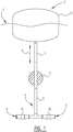
- Figure 1 schematically shows a an energy generating device, embodiments of which are described in WO 2006/051393 , for generating energy from an undulating movement of a medium such as seawater, wherein this movement is followed during the movement of the medium, wherein the followed movement is converted into energy, and wherein a direction of movement of the movement changes at a point in time.
- Figure 1 shows the water level 1.
- a part of energy generating device 2 is arranged in the water. The part is shown which, under the influence of swelling in water level 1, will cause a pumping action which can be used for energy generation.
- a turbine which will ultimately be used to convert the pumping action of the shown part of figure 1 into for instance electrical energy.
- the skilled person will be able to apply different energy generating means in suitable manner on the basis of the operation.
- Energy generating device 2 has a fixedly arranged frame 3, for instance fixedly connected to the seabed. This comprises a supply tube 4, a discharge tube 5 and a substantially vertically core pipe 6. The tubes are connected to a fluid source, for instance water. Through the action of energy generating device 2 water will be pumped, drawn in via feed 4 and pumped out via discharge 5. A turbine is for instance coupled to discharge 5 for the actual generation of energy.
- the standing core pipe 6 has for instance an outer surface of plastic and the sliding cover has for instance a thin stainless steel inner wall.
- a brass collar can for instance be arranged close to the outer end of core pipe 6. This can be connected thereto by means of an adhesive.
- a sliding fitting is hereby formed for the stainless steel cover.
- the standing core pipe 6 is also a stainless steel pipe too. The inner diameter of the outer pipe is drilled so that it obtains a smooth finish and the outer diameter of the inner pipe is ground with a precision cylindrical grinder so that a sliding fitting between the pipes is obtained. Blocking and leakage are hereby minimized.
- a float 13 is connected to cover 7, and floats in and on water level 1.
- the float 13 will be moved upward whereby the sleeve pipe 7 is moved upward as according to arrow 9, and the pump chamber is enlarged.
- a valve 15 is arranged in supply tube 4 and a valve 16 in discharge tube 5. The feed and/or the discharge can hereby be closed.
- Valves 15, 16 are actively regulated valves which can be switched, i.e. opened or closed, at determined times. The determined times at which switching takes place depend on the wave cycle.
- the control of valves 15, 16 can be connected to a control device (not shown). Given that the periodic time of sea wave swells is remarkably constant throughout the world and lies between 8 sec and 10 sec, it is imperative that the valves 15, 16 controlling inlet and outlet flows to a point source device must be able to switch off and on quickly (i.e. ⁇ 1 sec).
- the physical size of the sleeve pipe 7, core pipe 6 and the physical size and construction of the inlet control valve 15 and the outlet control valve 16 is dependent on the size of the float 13 as follows:
- the outlet valve 16 begins to open in a controlled manner to allow water to be discharged from the pump. Again the outlet valve 16 is closed in a sinusoidal motion so as to allow the float 13 to follow the inverse profile of the wave motion. It is at the end of the wave cycle that the need for fast switching becomes apparent because at that point the outlet valve 16 must be returned to the closed position and then the inlet valve 15 must be returned to the open position to allow the cycle to be repeated.
- valves 15, 16 are never fully open which means that the inflows and outflows are never maximized. Consequently there is an efficiency drop and this drop in efficiency will increase as the switching time is increased. So it is imperative that fast switching is realized.
- Ball valves and butterfly valves have round moving members and it has already been stated that large diameter moving parts are incapable of fast switching.
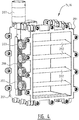
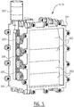
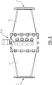
- FIGS 4 to 7 show a preferred embodiment of the inlet and outlet valve 15, 16 according to the invention.
- the valve 15, 16 comprises a tube section 201 having a rectangular cross section.
- a multitude of vanes 202 are rotatably mounted in the tube section 201.
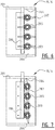
- the vanes 202 have a relatively large rectangular longitunal cross section to a first direction (as best seen in figure 5 ), a relatively small rectangular longitunal cross section in a second direction perpendicular to said first direction (as best seen in figure 4 ), and a generally flat-rhombic (or generally hydrofoil) cross section in a third direction perpendicular to said first and second directions (as best seen in figures 6 and 7 ).
- each vane 202 forms a closed water impermeable surface.
- the inner construction of the vanes 202 should be such that the vanes 202 are sufficiently stiff, so that the vanes 202 can withstand the high water pressure, yet are also lightweight, so that they can be rotated in a fast manner.
- shaft ends 203 extend from the vanes along the axis of the vanes 202, said shaft ends 203 extending through holes in said tube section 201, such that the axes of said multitude of vanes 202 all extend in a parallel manner.
- the distances between the axes are approximately half the distance between the outer tips of the vanes 202, seen in the cross section in said third direction (see figures 6 and 7 ), such that when the vanes 202 are rotated to the closed position as shown in figure 7 , the lower half of the front surfaces and upper half of the back surfaces of all vanes form a single closed front surface and a single closed back surface, each in substantially a single flat plane perpendicular to the flow axis of the valve, at least in the area between the two axes of the outermost vanes 202. Also in said closed position, the other half of said front surfaces and the other half of said back surfaces of said vanes 202 rest against each other.
- the array of vanes 202 can be rotated by means of a rack 206 mating with pinions 205 attached to the shaft ends 203 on at least one outer side of the tube section 202.
- the rack 206 is arranged to be moved up and down by a hydraulic cylinder 207, which cylinder 207 is in turn controlled by a hydraulic Moog valve.
- valve 15, 16 is shown in the open position which shows the rack 206 fully extended.
- valve 15, 16 is shown in the closed position which shows the rack 206 fully retracted.
- the vanes 202 are shaped in such a way as to minimize resistance to flow and also to allow them to come together in the closed position to form a comprehensive seal.
- the vanes 202 are interlocked in such a way as to create a full seal along the face of the blades so creating a watertight seal to withstand the pressures.
Landscapes
- Engineering & Computer Science (AREA)
- General Engineering & Computer Science (AREA)
- Mechanical Engineering (AREA)
- Chemical & Material Sciences (AREA)
- Combustion & Propulsion (AREA)
- Other Liquid Machine Or Engine Such As Wave Power Use (AREA)
Claims (7)
- Ein Verschlussklappenventil zum alternierenden Zulassen und Blockieren eines Hochdruck-Wasserstroms, aufweisend einen Abschnitt (201), der einen rechteckigen Querschnitt aufweist, mit einer Öffnung, wobei eine Vielzahl von Flügeln (202) drehbar in der Öffnung des Abschnitts (201) angebracht ist, wobei die Flügel (202) einen rechteckigen Längsquerschnitt in einer erster Richtung und einen rechteckigen Längsquerschnitt in einer zweiten Richtung, welche senkrecht zur ersten Richtung ist, aufweisen, wobei die Umfangswand um die Achse jedes Flügels (202) eine geschlossene, wasserundurchlässige Fläche bildet, wobei sich alle Achsen der Vielzahl von Flügeln (202) in einer parallelen Weise erstrecken, wobei, im Querschnitt in der dritten Richtung betrachtet, die Abstände zwischen den Achsen von benachbarten Flügeln (202) annähernd die Hälfte des Abstands zwischen den zwei äußersten Spitzen jedes Flügels (202) sind, so dass, wenn die Flügel (202) in die Geschlossen-Stellung gedreht sind, die untere Hälfte der Flächen an einer ersten Seite und die obere Hälfte der Flächen an einer zweiten Seite aller Flügel (202) jeweilig eine einzelne geschlossene Fläche an der ersten Seite und eine einzelne geschlossene Fläche an der zweiten Seite, jede im Wesentlichen in einer einzelnen flachen Ebene, welche senkrecht zur Strömungsachse des Ventils ist, bilden, wobei die Flächen die Öffnung des Abschnitts (201) verschließen, gekennzeichnet dadurch, dass die Flügel (202) einen rhombischen Querschnitt in einer dritten Richtung, welche zur ersten und zweiten Richtung senkrecht ist, aufweisen, wobei die dritte Richtung die Achse des Flügels ist, und die obere Hälfte der Flächen an der ersten Seite und die untere Hälfte der Flächen an der zweiten Seite der Flügel (202) aneinander anliegen, wenn die Flügel (202) in die Geschlossen-Stellung gedreht sind.
- Das Verschlussklappenventil gemäß Anspruch 1, wobei, an den Seiten neben den zwei äußeren Flügeln (202), die Spitzen der Flügel (202) gegen dazu passende Erhebungen (204) anliegen, welche sich von der inneren Wand des Abschnitts (201) aus erstrecken.
- Das Verschlussklappenventil gemäß Anspruch 2 oder 3, wobei sich an den äußeren Enden der Flügel (202) Wellenenden (203) von den Flügeln aus entlang der Achse der Flügel (202) erstrecken, wobei die Wellenenden (203) sich durch Löcher in dem Rohrabschnitt (201) erstrecken.
- Das Verschlussventil gemäß Anspruch 3, wobei die Gruppe von Flügeln (202) mittels einer Zahnstange (206), welche mit Ritzeln (205), die an den Wellenenden (203) an mindestens einer äußeren Seite des Rohrabschnitts (201) angebracht sind, im Eingriff ist, rotiert werden kann.
- Das Verschlussklappenventil gemäß Anspruch 4, wobei die Zahnstange (206) so angebracht ist, dass sie durch einen Hydraulikzylinder (207) bewegt wird,
- Das Verschlussklappenventil gemäß Anspruch 5, wobei der Zylinder (207) durch ein hydraulisches Moog-Ventil gesteuert wird.
- Eine Vorrichtung (2) zum Erzeugen von Energie aus Meereswellen (1), aufweisend einen Schwimmkörper (13) zum Nachfolgen der Bewegung von Meereswellen (1), eine Pumpenkammer (6, 7) mit einem variablen Volumen zum Aufbewahren eines variablen Wasservolumens, wobei das Pumpenkammervolumen derart eingerichtet ist, dass es sich durch die Kraft, welche durch den sich bewegenden Schwimmkörper (13) ausgeübt wird, verändert, wobei die Pumpenkammer (6, 7) ein Wasserzuführrohr 4 und ein Wasserablassrohr (5) aufweist, wobei das Wasserzuführrohr 4 und das Wasserablassrohr (5) jeweilig mit einem Ventil (15, 16) versehen sind, wobei die Ventile dazu eingerichtet sind, sich auf alternierende Weise zu öffnen und zu schließen mit einer Zyklusfrequenz, welche gleich der Zyklusfrequenz der Meereswellen (1) ist, wobei mindestens eines der Ventile (15, 16) ein Verschlussklappenventil gemäß irgendeinem der Ansprüche 1 - 6 ist.
Priority Applications (6)
| Application Number | Priority Date | Filing Date | Title |
|---|---|---|---|
| DK14171058.2T DK2952732T3 (en) | 2014-06-04 | 2014-06-04 | SHUTTER VALVE AND DEVICE FOR GENERATING ENERGY FROM SEA WAVES INCLUDING SUCH VALVES |
| EP14171058.2A EP2952732B1 (de) | 2014-06-04 | 2014-06-04 | Wechselventil und Vorrichtung zur Erzeugung von Energie aus Meereswellen mit solchen Ventilen |
| US15/315,475 US10145353B2 (en) | 2014-06-04 | 2015-06-02 | Shutter valve and device for generating energy from sea waves comprising such valves |
| CA2949730A CA2949730A1 (en) | 2014-06-04 | 2015-06-02 | Shutter valve and device for generating energy from sea waves comprising such valves |
| PCT/EP2015/062241 WO2015185543A1 (en) | 2014-06-04 | 2015-06-02 | Shutter valve and device for generating energy from sea waves comprising such valves |
| AU2015270618A AU2015270618B2 (en) | 2014-06-04 | 2015-06-02 | Shutter valve and device for generating energy from sea waves comprising such valves |
Applications Claiming Priority (1)
| Application Number | Priority Date | Filing Date | Title |
|---|---|---|---|
| EP14171058.2A EP2952732B1 (de) | 2014-06-04 | 2014-06-04 | Wechselventil und Vorrichtung zur Erzeugung von Energie aus Meereswellen mit solchen Ventilen |
Publications (2)
| Publication Number | Publication Date |
|---|---|
| EP2952732A1 EP2952732A1 (de) | 2015-12-09 |
| EP2952732B1 true EP2952732B1 (de) | 2019-01-02 |
Family
ID=50943085
Family Applications (1)
| Application Number | Title | Priority Date | Filing Date |
|---|---|---|---|
| EP14171058.2A Not-in-force EP2952732B1 (de) | 2014-06-04 | 2014-06-04 | Wechselventil und Vorrichtung zur Erzeugung von Energie aus Meereswellen mit solchen Ventilen |
Country Status (6)
| Country | Link |
|---|---|
| US (1) | US10145353B2 (de) |
| EP (1) | EP2952732B1 (de) |
| AU (1) | AU2015270618B2 (de) |
| CA (1) | CA2949730A1 (de) |
| DK (1) | DK2952732T3 (de) |
| WO (1) | WO2015185543A1 (de) |
Families Citing this family (2)
| Publication number | Priority date | Publication date | Assignee | Title |
|---|---|---|---|---|
| CN113531132B (zh) * | 2021-07-26 | 2022-09-16 | 浙江欧盾风机有限公司 | 一种降噪型防火阀及其制造工艺 |
| CN114215020B (zh) * | 2022-01-14 | 2022-06-21 | 中国电建集团贵阳勘测设计研究院有限公司 | 一种高效快捷的无级分层取水闸门装置 |
Family Cites Families (27)
| Publication number | Priority date | Publication date | Assignee | Title |
|---|---|---|---|---|
| DE285438C (de) * | ||||
| GB188728A (en) * | 1921-07-23 | 1922-11-23 | Armin Tetetleni | Improvements relating to turbines and the like |
| US3426507A (en) * | 1964-12-23 | 1969-02-11 | Joy Mfg Co | Electrical precipitator |
| US3549438A (en) * | 1967-05-23 | 1970-12-22 | Dow Chemical Co | Method and apparatus for etching curved surfaces |
| US3620242A (en) * | 1970-01-05 | 1971-11-16 | Babcock & Wilcox Co | Self-cleaning damper assembly |
| US3749115A (en) * | 1971-12-29 | 1973-07-31 | Combustion Eng | Damper apparatus with fluid seal |
| US4077432A (en) * | 1977-01-05 | 1978-03-07 | Mosser Industries, Inc. | Purged valve |
| US4191212A (en) * | 1977-05-18 | 1980-03-04 | Damper Design, Inc. | Multiple blade damper assembly |
| USRE31471E (en) * | 1977-05-18 | 1983-12-27 | Damper Design, Inc. | Multiple blade damper assembly |
| US4187878A (en) | 1977-12-23 | 1980-02-12 | Zurn Industries, Inc. | Valve having internally pressurized sealing elements |
| DE3023639A1 (de) * | 1980-06-24 | 1982-01-21 | Janich, geb.Fischer, Elsbeth, 4720 Beckum | Vorrichtung zum absperren grosser rohrleitungen |
| EP0053458B1 (de) * | 1980-12-01 | 1985-09-11 | Secretary of State for Energy in Her Britannic Majesty's Gov. of the United Kingdom of Great Britain and Northern Ireland | Wellenenergieumwandler |
| US4594853A (en) * | 1984-03-12 | 1986-06-17 | Wave Power Industries | Wave powered generator |
| US4698969A (en) * | 1984-03-12 | 1987-10-13 | Wave Power Industries, Ltd. | Wave power converter |
| US5000422A (en) * | 1990-06-29 | 1991-03-19 | Salem Industries, Inc. | Incinerator valve |
| DE4030611A1 (de) * | 1990-09-27 | 1992-04-02 | Mannesmann Ag | Absperrorgan |
| US5105094A (en) * | 1991-03-07 | 1992-04-14 | Parker Percy C | Method and apparatus for converting wave motion into an alternative energy source |
| US5947051A (en) * | 1997-06-04 | 1999-09-07 | Geiger; Michael B. | Underwater self-propelled surface adhering robotically operated vehicle |
| NL1015196C2 (nl) * | 2000-05-12 | 2001-11-19 | Zakaria Khalil Doleh | Inrichting voor het opslaan van potentiÙle energie. |
| NL1027469C2 (nl) * | 2004-11-10 | 2006-05-17 | Zakaria Khalil Doleh | Werkwijze en inrichting voor het opwekken van energie uit een beweging van een medium zoals zeewater. |
| US7355298B2 (en) * | 2006-03-17 | 2008-04-08 | Glen Edward Cook | Syphon wave generator |
| CN101956647B (zh) * | 2009-07-15 | 2012-12-19 | 鸿富锦精密工业(深圳)有限公司 | 潮汐能发电装置 |
| US8698338B2 (en) * | 2010-03-08 | 2014-04-15 | Massachusetts Institute Of Technology | Offshore energy harvesting, storage, and power generation system |
| US9261069B2 (en) * | 2011-06-23 | 2016-02-16 | Elazar Tagansky | Sloping wall channel |
| US9395098B2 (en) * | 2012-07-06 | 2016-07-19 | Ruskin Company | Damper blade seal system |
| RU2525986C2 (ru) * | 2012-09-14 | 2014-08-20 | Владимир Эдуардович Егурнов | Устройство для отбора энергии морских волн |
| US9625174B2 (en) * | 2014-03-25 | 2017-04-18 | Ruskin Company | Air control damper with retracting end blade stop |
-
2014
- 2014-06-04 EP EP14171058.2A patent/EP2952732B1/de not_active Not-in-force
- 2014-06-04 DK DK14171058.2T patent/DK2952732T3/en active
-
2015
- 2015-06-02 WO PCT/EP2015/062241 patent/WO2015185543A1/en not_active Ceased
- 2015-06-02 AU AU2015270618A patent/AU2015270618B2/en not_active Ceased
- 2015-06-02 US US15/315,475 patent/US10145353B2/en active Active
- 2015-06-02 CA CA2949730A patent/CA2949730A1/en active Pending
Non-Patent Citations (1)
| Title |
|---|
| None * |
Also Published As
| Publication number | Publication date |
|---|---|
| AU2015270618A8 (en) | 2017-02-02 |
| US20180209396A1 (en) | 2018-07-26 |
| EP2952732A1 (de) | 2015-12-09 |
| CA2949730A1 (en) | 2015-12-10 |
| WO2015185543A1 (en) | 2015-12-10 |
| AU2015270618B2 (en) | 2019-01-31 |
| DK2952732T3 (en) | 2019-04-08 |
| AU2015270618A1 (en) | 2016-12-08 |
| US10145353B2 (en) | 2018-12-04 |
Similar Documents
| Publication | Publication Date | Title |
|---|---|---|
| Müller et al. | Simplified theory of Archimedean screws | |
| EP2952732B1 (de) | Wechselventil und Vorrichtung zur Erzeugung von Energie aus Meereswellen mit solchen Ventilen | |
| KR101424053B1 (ko) | 조력발전장치 | |
| BRPI0918552B1 (pt) | Aparelho de flutuação longo, e, método de coleta de um componente horizontal de energia cinética das ondas em movimentos de onda de água oscilante | |
| US20180023533A1 (en) | Hydroelectric power generation device for pipeline | |
| CN113439160B (zh) | 泵送系统和流体输送装置 | |
| CN109574137A (zh) | 一种厨房用油水分离装置 | |
| KR101841135B1 (ko) | 파력기관 및, 이를 이용한 발전장치와 수상교통장치 | |
| KR101561081B1 (ko) | 물의 흐름을 이용한 무동력 양방향 양수장치 | |
| DK3194761T3 (en) | A FREE FLYING WAVE ENERGY ENVIRONMENT WITH VARIABLE BUILDING, FLEXIBLE PIPES AND PREPARED Capture Width | |
| KR20110031399A (ko) | 날개 접이식 수차와 수차집 | |
| CN204059304U (zh) | 水力自动翻转堰 | |
| RU2465488C1 (ru) | Подводный гидравлический таран | |
| US20250075677A1 (en) | Power generation from moving water | |
| NL1041539B1 (en) | High capacity factor hydro power plant with variable intake | |
| RU111547U1 (ru) | Гидравлическое устройство для очистки от осевших наносов водопропускных труб, имеющих положительный уклон дна | |
| FI120888B (fi) | Voimalaitos | |
| Nikodijevic et al. | Valve selection for the purpose of reducing the water hammer effect in a pressurized pipeline | |
| WO2018150387A1 (en) | A depending wave pump | |
| JP3113225U (ja) | 水力空気発電装置 | |
| US20220136480A1 (en) | Modular device for converting wave energy | |
| KR101566427B1 (ko) | 수로관의 무게 추를 이용한 개폐문 장치 | |
| HK40059509A (en) | Pumping system and fluid delivery installation | |
| KR200294336Y1 (ko) | 계곡수 저장용 원통형 저장탱크 | |
| UA122935U (uk) | Спосіб покращення екологічних показників малодинамічних водних об'єктів |
Legal Events
| Date | Code | Title | Description |
|---|---|---|---|
| PUAI | Public reference made under article 153(3) epc to a published international application that has entered the european phase |
Free format text: ORIGINAL CODE: 0009012 |
|
| AK | Designated contracting states |
Kind code of ref document: A1 Designated state(s): AL AT BE BG CH CY CZ DE DK EE ES FI FR GB GR HR HU IE IS IT LI LT LU LV MC MK MT NL NO PL PT RO RS SE SI SK SM TR |
|
| AX | Request for extension of the european patent |
Extension state: BA ME |
|
| 17P | Request for examination filed |
Effective date: 20160525 |
|
| RBV | Designated contracting states (corrected) |
Designated state(s): AL AT BE BG CH CY CZ DE DK EE ES FI FR GB GR HR HU IE IS IT LI LT LU LV MC MK MT NL NO PL PT RO RS SE SI SK SM TR |
|
| REG | Reference to a national code |
Ref country code: DE Ref legal event code: R079 Ref document number: 602014038976 Country of ref document: DE Free format text: PREVIOUS MAIN CLASS: F03B0013180000 Ipc: F16K0031163000 |
|
| GRAP | Despatch of communication of intention to grant a patent |
Free format text: ORIGINAL CODE: EPIDOSNIGR1 |
|
| STAA | Information on the status of an ep patent application or granted ep patent |
Free format text: STATUS: GRANT OF PATENT IS INTENDED |
|
| RIC1 | Information provided on ipc code assigned before grant |
Ipc: F16K 31/163 20060101AFI20180903BHEP Ipc: F16K 1/22 20060101ALI20180903BHEP Ipc: F03B 13/18 20060101ALI20180903BHEP Ipc: F03B 13/20 20060101ALI20180903BHEP Ipc: F16K 31/54 20060101ALI20180903BHEP |
|
| INTG | Intention to grant announced |
Effective date: 20181002 |
|
| GRAS | Grant fee paid |
Free format text: ORIGINAL CODE: EPIDOSNIGR3 |
|
| GRAA | (expected) grant |
Free format text: ORIGINAL CODE: 0009210 |
|
| STAA | Information on the status of an ep patent application or granted ep patent |
Free format text: STATUS: THE PATENT HAS BEEN GRANTED |
|
| RAP1 | Party data changed (applicant data changed or rights of an application transferred) |
Owner name: DOLEH, ZAKARIA KHALIL IBRAHIM Owner name: LOCK, JOHN DOUGLAS |
|
| RIN1 | Information on inventor provided before grant (corrected) |
Inventor name: LOCK, JOHN DOUGLAS Inventor name: DOLEH, ZAKARIA KHALIL IBRAHIM |
|
| AK | Designated contracting states |
Kind code of ref document: B1 Designated state(s): AL AT BE BG CH CY CZ DE DK EE ES FI FR GB GR HR HU IE IS IT LI LT LU LV MC MK MT NL NO PL PT RO RS SE SI SK SM TR |
|
| REG | Reference to a national code |
Ref country code: GB Ref legal event code: FG4D |
|
| REG | Reference to a national code |
Ref country code: CH Ref legal event code: EP Ref country code: AT Ref legal event code: REF Ref document number: 1084812 Country of ref document: AT Kind code of ref document: T Effective date: 20190115 |
|
| REG | Reference to a national code |
Ref country code: IE Ref legal event code: FG4D |
|
| REG | Reference to a national code |
Ref country code: DE Ref legal event code: R096 Ref document number: 602014038976 Country of ref document: DE |
|
| REG | Reference to a national code |
Ref country code: DK Ref legal event code: T3 Effective date: 20190401 |
|
| REG | Reference to a national code |
Ref country code: SE Ref legal event code: TRGR |
|
| REG | Reference to a national code |
Ref country code: NL Ref legal event code: MP Effective date: 20190102 |
|
| REG | Reference to a national code |
Ref country code: LT Ref legal event code: MG4D |
|
| REG | Reference to a national code |
Ref country code: NO Ref legal event code: T2 Effective date: 20190102 |
|
| REG | Reference to a national code |
Ref country code: AT Ref legal event code: MK05 Ref document number: 1084812 Country of ref document: AT Kind code of ref document: T Effective date: 20190102 |
|
| PG25 | Lapsed in a contracting state [announced via postgrant information from national office to epo] |
Ref country code: NL Free format text: LAPSE BECAUSE OF FAILURE TO SUBMIT A TRANSLATION OF THE DESCRIPTION OR TO PAY THE FEE WITHIN THE PRESCRIBED TIME-LIMIT Effective date: 20190102 |
|
| PG25 | Lapsed in a contracting state [announced via postgrant information from national office to epo] |
Ref country code: LT Free format text: LAPSE BECAUSE OF FAILURE TO SUBMIT A TRANSLATION OF THE DESCRIPTION OR TO PAY THE FEE WITHIN THE PRESCRIBED TIME-LIMIT Effective date: 20190102 Ref country code: PT Free format text: LAPSE BECAUSE OF FAILURE TO SUBMIT A TRANSLATION OF THE DESCRIPTION OR TO PAY THE FEE WITHIN THE PRESCRIBED TIME-LIMIT Effective date: 20190502 Ref country code: ES Free format text: LAPSE BECAUSE OF FAILURE TO SUBMIT A TRANSLATION OF THE DESCRIPTION OR TO PAY THE FEE WITHIN THE PRESCRIBED TIME-LIMIT Effective date: 20190102 Ref country code: PL Free format text: LAPSE BECAUSE OF FAILURE TO SUBMIT A TRANSLATION OF THE DESCRIPTION OR TO PAY THE FEE WITHIN THE PRESCRIBED TIME-LIMIT Effective date: 20190102 |
|
| PG25 | Lapsed in a contracting state [announced via postgrant information from national office to epo] |
Ref country code: IS Free format text: LAPSE BECAUSE OF FAILURE TO SUBMIT A TRANSLATION OF THE DESCRIPTION OR TO PAY THE FEE WITHIN THE PRESCRIBED TIME-LIMIT Effective date: 20190502 Ref country code: LV Free format text: LAPSE BECAUSE OF FAILURE TO SUBMIT A TRANSLATION OF THE DESCRIPTION OR TO PAY THE FEE WITHIN THE PRESCRIBED TIME-LIMIT Effective date: 20190102 Ref country code: GR Free format text: LAPSE BECAUSE OF FAILURE TO SUBMIT A TRANSLATION OF THE DESCRIPTION OR TO PAY THE FEE WITHIN THE PRESCRIBED TIME-LIMIT Effective date: 20190403 Ref country code: HR Free format text: LAPSE BECAUSE OF FAILURE TO SUBMIT A TRANSLATION OF THE DESCRIPTION OR TO PAY THE FEE WITHIN THE PRESCRIBED TIME-LIMIT Effective date: 20190102 Ref country code: RS Free format text: LAPSE BECAUSE OF FAILURE TO SUBMIT A TRANSLATION OF THE DESCRIPTION OR TO PAY THE FEE WITHIN THE PRESCRIBED TIME-LIMIT Effective date: 20190102 Ref country code: BG Free format text: LAPSE BECAUSE OF FAILURE TO SUBMIT A TRANSLATION OF THE DESCRIPTION OR TO PAY THE FEE WITHIN THE PRESCRIBED TIME-LIMIT Effective date: 20190402 |
|
| REG | Reference to a national code |
Ref country code: DE Ref legal event code: R097 Ref document number: 602014038976 Country of ref document: DE |
|
| PG25 | Lapsed in a contracting state [announced via postgrant information from national office to epo] |
Ref country code: AL Free format text: LAPSE BECAUSE OF FAILURE TO SUBMIT A TRANSLATION OF THE DESCRIPTION OR TO PAY THE FEE WITHIN THE PRESCRIBED TIME-LIMIT Effective date: 20190102 Ref country code: RO Free format text: LAPSE BECAUSE OF FAILURE TO SUBMIT A TRANSLATION OF THE DESCRIPTION OR TO PAY THE FEE WITHIN THE PRESCRIBED TIME-LIMIT Effective date: 20190102 Ref country code: CZ Free format text: LAPSE BECAUSE OF FAILURE TO SUBMIT A TRANSLATION OF THE DESCRIPTION OR TO PAY THE FEE WITHIN THE PRESCRIBED TIME-LIMIT Effective date: 20190102 Ref country code: AT Free format text: LAPSE BECAUSE OF FAILURE TO SUBMIT A TRANSLATION OF THE DESCRIPTION OR TO PAY THE FEE WITHIN THE PRESCRIBED TIME-LIMIT Effective date: 20190102 Ref country code: EE Free format text: LAPSE BECAUSE OF FAILURE TO SUBMIT A TRANSLATION OF THE DESCRIPTION OR TO PAY THE FEE WITHIN THE PRESCRIBED TIME-LIMIT Effective date: 20190102 Ref country code: IT Free format text: LAPSE BECAUSE OF FAILURE TO SUBMIT A TRANSLATION OF THE DESCRIPTION OR TO PAY THE FEE WITHIN THE PRESCRIBED TIME-LIMIT Effective date: 20190102 Ref country code: SK Free format text: LAPSE BECAUSE OF FAILURE TO SUBMIT A TRANSLATION OF THE DESCRIPTION OR TO PAY THE FEE WITHIN THE PRESCRIBED TIME-LIMIT Effective date: 20190102 |
|
| PLBE | No opposition filed within time limit |
Free format text: ORIGINAL CODE: 0009261 |
|
| STAA | Information on the status of an ep patent application or granted ep patent |
Free format text: STATUS: NO OPPOSITION FILED WITHIN TIME LIMIT |
|
| PG25 | Lapsed in a contracting state [announced via postgrant information from national office to epo] |
Ref country code: SM Free format text: LAPSE BECAUSE OF FAILURE TO SUBMIT A TRANSLATION OF THE DESCRIPTION OR TO PAY THE FEE WITHIN THE PRESCRIBED TIME-LIMIT Effective date: 20190102 |
|
| 26N | No opposition filed |
Effective date: 20191003 |
|
| PG25 | Lapsed in a contracting state [announced via postgrant information from national office to epo] |
Ref country code: MC Free format text: LAPSE BECAUSE OF FAILURE TO SUBMIT A TRANSLATION OF THE DESCRIPTION OR TO PAY THE FEE WITHIN THE PRESCRIBED TIME-LIMIT Effective date: 20190102 |
|
| REG | Reference to a national code |
Ref country code: CH Ref legal event code: PL |
|
| PG25 | Lapsed in a contracting state [announced via postgrant information from national office to epo] |
Ref country code: SI Free format text: LAPSE BECAUSE OF FAILURE TO SUBMIT A TRANSLATION OF THE DESCRIPTION OR TO PAY THE FEE WITHIN THE PRESCRIBED TIME-LIMIT Effective date: 20190102 |
|
| REG | Reference to a national code |
Ref country code: BE Ref legal event code: MM Effective date: 20190630 |
|
| PG25 | Lapsed in a contracting state [announced via postgrant information from national office to epo] |
Ref country code: TR Free format text: LAPSE BECAUSE OF FAILURE TO SUBMIT A TRANSLATION OF THE DESCRIPTION OR TO PAY THE FEE WITHIN THE PRESCRIBED TIME-LIMIT Effective date: 20190102 |
|
| PG25 | Lapsed in a contracting state [announced via postgrant information from national office to epo] |
Ref country code: IE Free format text: LAPSE BECAUSE OF NON-PAYMENT OF DUE FEES Effective date: 20190604 |
|
| PG25 | Lapsed in a contracting state [announced via postgrant information from national office to epo] |
Ref country code: CH Free format text: LAPSE BECAUSE OF NON-PAYMENT OF DUE FEES Effective date: 20190630 Ref country code: BE Free format text: LAPSE BECAUSE OF NON-PAYMENT OF DUE FEES Effective date: 20190630 Ref country code: LI Free format text: LAPSE BECAUSE OF NON-PAYMENT OF DUE FEES Effective date: 20190630 Ref country code: LU Free format text: LAPSE BECAUSE OF NON-PAYMENT OF DUE FEES Effective date: 20190604 |
|
| PG25 | Lapsed in a contracting state [announced via postgrant information from national office to epo] |
Ref country code: CY Free format text: LAPSE BECAUSE OF FAILURE TO SUBMIT A TRANSLATION OF THE DESCRIPTION OR TO PAY THE FEE WITHIN THE PRESCRIBED TIME-LIMIT Effective date: 20190102 |
|
| PG25 | Lapsed in a contracting state [announced via postgrant information from national office to epo] |
Ref country code: MT Free format text: LAPSE BECAUSE OF FAILURE TO SUBMIT A TRANSLATION OF THE DESCRIPTION OR TO PAY THE FEE WITHIN THE PRESCRIBED TIME-LIMIT Effective date: 20190102 Ref country code: HU Free format text: LAPSE BECAUSE OF FAILURE TO SUBMIT A TRANSLATION OF THE DESCRIPTION OR TO PAY THE FEE WITHIN THE PRESCRIBED TIME-LIMIT; INVALID AB INITIO Effective date: 20140604 |
|
| PG25 | Lapsed in a contracting state [announced via postgrant information from national office to epo] |
Ref country code: MK Free format text: LAPSE BECAUSE OF FAILURE TO SUBMIT A TRANSLATION OF THE DESCRIPTION OR TO PAY THE FEE WITHIN THE PRESCRIBED TIME-LIMIT Effective date: 20190102 |
|
| PGFP | Annual fee paid to national office [announced via postgrant information from national office to epo] |
Ref country code: FR Payment date: 20221025 Year of fee payment: 9 |
|
| PGFP | Annual fee paid to national office [announced via postgrant information from national office to epo] |
Ref country code: SE Payment date: 20221027 Year of fee payment: 9 Ref country code: NO Payment date: 20221027 Year of fee payment: 9 Ref country code: GB Payment date: 20221027 Year of fee payment: 9 Ref country code: FI Payment date: 20221027 Year of fee payment: 9 Ref country code: DK Payment date: 20221027 Year of fee payment: 9 Ref country code: DE Payment date: 20221027 Year of fee payment: 9 |
|
| REG | Reference to a national code |
Ref country code: DE Ref legal event code: R119 Ref document number: 602014038976 Country of ref document: DE |
|
| REG | Reference to a national code |
Ref country code: NO Ref legal event code: MMEP Ref country code: DK Ref legal event code: EBP Effective date: 20230630 |
|
| REG | Reference to a national code |
Ref country code: SE Ref legal event code: EUG |
|
| PG25 | Lapsed in a contracting state [announced via postgrant information from national office to epo] |
Ref country code: FI Free format text: LAPSE BECAUSE OF NON-PAYMENT OF DUE FEES Effective date: 20230604 |
|
| GBPC | Gb: european patent ceased through non-payment of renewal fee |
Effective date: 20230604 |
|
| PG25 | Lapsed in a contracting state [announced via postgrant information from national office to epo] |
Ref country code: DE Free format text: LAPSE BECAUSE OF NON-PAYMENT OF DUE FEES Effective date: 20240103 Ref country code: GB Free format text: LAPSE BECAUSE OF NON-PAYMENT OF DUE FEES Effective date: 20230604 |
|
| PG25 | Lapsed in a contracting state [announced via postgrant information from national office to epo] |
Ref country code: SE Free format text: LAPSE BECAUSE OF NON-PAYMENT OF DUE FEES Effective date: 20230605 Ref country code: NO Free format text: LAPSE BECAUSE OF NON-PAYMENT OF DUE FEES Effective date: 20230630 Ref country code: FR Free format text: LAPSE BECAUSE OF NON-PAYMENT OF DUE FEES Effective date: 20230630 |
|
| PG25 | Lapsed in a contracting state [announced via postgrant information from national office to epo] |
Ref country code: DK Free format text: LAPSE BECAUSE OF NON-PAYMENT OF DUE FEES Effective date: 20230630 |
|
| PG25 | Lapsed in a contracting state [announced via postgrant information from national office to epo] |
Ref country code: DK Free format text: LAPSE BECAUSE OF NON-PAYMENT OF DUE FEES Effective date: 20230630 |