EP2952737B1 - Isolation de palier - Google Patents
Isolation de palier Download PDFInfo
- Publication number
- EP2952737B1 EP2952737B1 EP14171362.8A EP14171362A EP2952737B1 EP 2952737 B1 EP2952737 B1 EP 2952737B1 EP 14171362 A EP14171362 A EP 14171362A EP 2952737 B1 EP2952737 B1 EP 2952737B1
- Authority
- EP
- European Patent Office
- Prior art keywords
- electrical insulation
- insulation element
- bearing
- bearing system
- ring
- Prior art date
- Legal status (The legal status is an assumption and is not a legal conclusion. Google has not performed a legal analysis and makes no representation as to the accuracy of the status listed.)
- Not-in-force
Links
- 238000009413 insulation Methods 0.000 title description 22
- 238000010292 electrical insulation Methods 0.000 claims description 101
- 229910052751 metal Inorganic materials 0.000 claims description 49
- 239000002184 metal Substances 0.000 claims description 42
- 239000003365 glass fiber Substances 0.000 claims description 26
- 230000005672 electromagnetic field Effects 0.000 claims description 11
- 239000011248 coating agent Substances 0.000 claims description 8
- 238000000576 coating method Methods 0.000 claims description 8
- 239000011152 fibreglass Substances 0.000 description 8
- 238000000034 method Methods 0.000 description 6
- 229910000831 Steel Inorganic materials 0.000 description 5
- 238000007599 discharging Methods 0.000 description 5
- 239000011888 foil Substances 0.000 description 5
- 239000010959 steel Substances 0.000 description 5
- 239000000463 material Substances 0.000 description 4
- 230000008439 repair process Effects 0.000 description 4
- 230000008878 coupling Effects 0.000 description 3
- 238000010168 coupling process Methods 0.000 description 3
- 238000005859 coupling reaction Methods 0.000 description 3
- 238000004519 manufacturing process Methods 0.000 description 3
- 230000000903 blocking effect Effects 0.000 description 2
- 238000010276 construction Methods 0.000 description 2
- 230000001419 dependent effect Effects 0.000 description 2
- 239000012774 insulation material Substances 0.000 description 2
- 238000005086 pumping Methods 0.000 description 2
- 230000002441 reversible effect Effects 0.000 description 2
- 238000005096 rolling process Methods 0.000 description 2
- 238000003466 welding Methods 0.000 description 2
- 241000283690 Bos taurus Species 0.000 description 1
- OKTJSMMVPCPJKN-UHFFFAOYSA-N Carbon Chemical compound [C] OKTJSMMVPCPJKN-UHFFFAOYSA-N 0.000 description 1
- 208000025274 Lightning injury Diseases 0.000 description 1
- 239000003570 air Substances 0.000 description 1
- 239000012080 ambient air Substances 0.000 description 1
- 230000009286 beneficial effect Effects 0.000 description 1
- 239000003990 capacitor Substances 0.000 description 1
- 238000005266 casting Methods 0.000 description 1
- 230000015556 catabolic process Effects 0.000 description 1
- 230000008859 change Effects 0.000 description 1
- 238000005520 cutting process Methods 0.000 description 1
- 230000007423 decrease Effects 0.000 description 1
- 230000003247 decreasing effect Effects 0.000 description 1
- 230000005684 electric field Effects 0.000 description 1
- 239000003292 glue Substances 0.000 description 1
- 229910002804 graphite Inorganic materials 0.000 description 1
- 239000010439 graphite Substances 0.000 description 1
- 238000002955 isolation Methods 0.000 description 1
- 238000005461 lubrication Methods 0.000 description 1
- 230000007246 mechanism Effects 0.000 description 1
- 230000008569 process Effects 0.000 description 1
- 239000011347 resin Substances 0.000 description 1
- 229920005989 resin Polymers 0.000 description 1
Images


Classifications
-
- F—MECHANICAL ENGINEERING; LIGHTING; HEATING; WEAPONS; BLASTING
- F16—ENGINEERING ELEMENTS AND UNITS; GENERAL MEASURES FOR PRODUCING AND MAINTAINING EFFECTIVE FUNCTIONING OF MACHINES OR INSTALLATIONS; THERMAL INSULATION IN GENERAL
- F16C—SHAFTS; FLEXIBLE SHAFTS; ELEMENTS OR CRANKSHAFT MECHANISMS; ROTARY BODIES OTHER THAN GEARING ELEMENTS; BEARINGS
- F16C19/00—Bearings with rolling contact, for exclusively rotary movement
- F16C19/52—Bearings with rolling contact, for exclusively rotary movement with devices affected by abnormal or undesired conditions
-
- F—MECHANICAL ENGINEERING; LIGHTING; HEATING; WEAPONS; BLASTING
- F03—MACHINES OR ENGINES FOR LIQUIDS; WIND, SPRING, OR WEIGHT MOTORS; PRODUCING MECHANICAL POWER OR A REACTIVE PROPULSIVE THRUST, NOT OTHERWISE PROVIDED FOR
- F03D—WIND MOTORS
- F03D80/00—Details, components or accessories not provided for in groups F03D1/00 - F03D17/00
- F03D80/70—Bearing or lubricating arrangements
-
- F—MECHANICAL ENGINEERING; LIGHTING; HEATING; WEAPONS; BLASTING
- F16—ENGINEERING ELEMENTS AND UNITS; GENERAL MEASURES FOR PRODUCING AND MAINTAINING EFFECTIVE FUNCTIONING OF MACHINES OR INSTALLATIONS; THERMAL INSULATION IN GENERAL
- F16C—SHAFTS; FLEXIBLE SHAFTS; ELEMENTS OR CRANKSHAFT MECHANISMS; ROTARY BODIES OTHER THAN GEARING ELEMENTS; BEARINGS
- F16C35/00—Rigid support of bearing units; Housings, e.g. caps, covers
- F16C35/04—Rigid support of bearing units; Housings, e.g. caps, covers in the case of ball or roller bearings
- F16C35/06—Mounting or dismounting of ball or roller bearings; Fixing them onto shaft or in housing
- F16C35/07—Fixing them on the shaft or housing with interposition of an element
-
- F—MECHANICAL ENGINEERING; LIGHTING; HEATING; WEAPONS; BLASTING
- F05—INDEXING SCHEMES RELATING TO ENGINES OR PUMPS IN VARIOUS SUBCLASSES OF CLASSES F01-F04
- F05B—INDEXING SCHEME RELATING TO WIND, SPRING, WEIGHT, INERTIA OR LIKE MOTORS, TO MACHINES OR ENGINES FOR LIQUIDS COVERED BY SUBCLASSES F03B, F03D AND F03G
- F05B2240/00—Components
- F05B2240/50—Bearings
-
- F—MECHANICAL ENGINEERING; LIGHTING; HEATING; WEAPONS; BLASTING
- F16—ENGINEERING ELEMENTS AND UNITS; GENERAL MEASURES FOR PRODUCING AND MAINTAINING EFFECTIVE FUNCTIONING OF MACHINES OR INSTALLATIONS; THERMAL INSULATION IN GENERAL
- F16C—SHAFTS; FLEXIBLE SHAFTS; ELEMENTS OR CRANKSHAFT MECHANISMS; ROTARY BODIES OTHER THAN GEARING ELEMENTS; BEARINGS
- F16C2300/00—Application independent of particular apparatuses
- F16C2300/10—Application independent of particular apparatuses related to size
- F16C2300/14—Large applications, e.g. bearings having an inner diameter exceeding 500 mm
-
- F—MECHANICAL ENGINEERING; LIGHTING; HEATING; WEAPONS; BLASTING
- F16—ENGINEERING ELEMENTS AND UNITS; GENERAL MEASURES FOR PRODUCING AND MAINTAINING EFFECTIVE FUNCTIONING OF MACHINES OR INSTALLATIONS; THERMAL INSULATION IN GENERAL
- F16C—SHAFTS; FLEXIBLE SHAFTS; ELEMENTS OR CRANKSHAFT MECHANISMS; ROTARY BODIES OTHER THAN GEARING ELEMENTS; BEARINGS
- F16C2360/00—Engines or pumps
- F16C2360/31—Wind motors
-
- Y—GENERAL TAGGING OF NEW TECHNOLOGICAL DEVELOPMENTS; GENERAL TAGGING OF CROSS-SECTIONAL TECHNOLOGIES SPANNING OVER SEVERAL SECTIONS OF THE IPC; TECHNICAL SUBJECTS COVERED BY FORMER USPC CROSS-REFERENCE ART COLLECTIONS [XRACs] AND DIGESTS
- Y02—TECHNOLOGIES OR APPLICATIONS FOR MITIGATION OR ADAPTATION AGAINST CLIMATE CHANGE
- Y02E—REDUCTION OF GREENHOUSE GAS [GHG] EMISSIONS, RELATED TO ENERGY GENERATION, TRANSMISSION OR DISTRIBUTION
- Y02E10/00—Energy generation through renewable energy sources
- Y02E10/70—Wind energy
- Y02E10/72—Wind turbines with rotation axis in wind direction
Definitions
- the present invention relates to the field of wind turbines.
- the rotor of a direct drive generator for wind turbines has a diameter of more than 4m, dependent on the generator power and torque.
- the generator rotor of the Siemens Wind Power direct drive turbines for example has an outer diameter of 4.2m for the SWP 3.0-101 and an outer diameter of 6.5m for the SWP 6.0-154 and a length of around 2.5m.
- the rotor consists of a front plate, a rotor ring with a certain yoke height and a bearing ring.
- the complete rotor is also called rotor housing because in the Siemens Wind Power direct drive turbines the rotor is located outside of the stator and acts therefore like a house.
- the rotor outer surface is directly in contact with the ambient air.
- the rotor housing of all the direct drive Siemens Wind Power generators is a single welded and machined steel component.
- the rotor housing consists of two large cones, which are welded together with a forged steel ring and a rolled steel yoke. This rotor housing is then machined in a large CNC machine.
- Damaged bearings can cause generator failures, which lead to unplanned downtime and costly repairs.
- a single month's wait for parts is unrealistically short considering the worldwide shortage of bearings and other key components.
- On top of lost revenue is the cost of repairing failed bearings due to for example new bearings, labour, slip rings, and other parts, but also enormous expense of renting and transporting the large crane needed for many repairs must be accounted for.
- Bearing currents caused by stator-to-rotor capacitive coupling must be diverted from the shaft by providing a least resistance path to ground other than the bearing themselves.
- EP 2620643 A1 discloses a bearing system for a wind turbine, wherein the bearing system comprises a first bearing rind, a first seal carrier, a second bearing ring, a second seal carrier and a roller element.
- the first bearing ring has a first surface to which a first turbine element of the wind turbine is coupleable.
- the first seal carrier is mounted to the first surface of the first bearing ring such that the first seal carrier is locatable between the first bearing ring and the first turbine element.
- the first seal carrier is made of an electrically isolating material for electrically isolating the first bearing ring to the first turbine element.
- Fiber glass laminates acts as a good insulation for direct current and low frequency current to enter the bearing, but this is not useful for very high frequency currents, as the capacitance impedance reduces as frequency increase.
- shaft grounding brushes are also used to ground stray currents, but this is also not useful to ground very high frequency currents.
- the problem addressed in this document is related to generator shaft currents where induced current causes damage to the main bearing of a wind turbine generator. Therefore an electrical insulation of the main bearing may be needed to avoid failure of the generator. Such an electrical insulation increases the effort for producing a direct drive generator. Hence, there may be a need to produce a direct drive generator with an outer rotor in an easier and cost reducing manner.
- a rotor housing for a wind turbine with a generator with an outer rotor may comprise a support structure, wherein the support structure is cylindrical shaped, a front structure, a ring and an electrical insulation element.
- the ring and the front structure are attached together at an inner side of the front structure in a horizontal plane forming a front part of the rotor housing.
- the support structure is attached to the front structure at a front end of the support structure forming a side part of the rotor housing.
- the electrical insulation element is arranged between the front part of the rotor housing and the side part of the rotor housing.
- the support structure according to the invention may be the yoke of the rotor housing.
- the front structure according to the invention may be for example shaped like a cone.
- the ring may be used to receive bearings or a bearing system used for the rotation of the rotor, and therefore may act as bearing or bearing system housing. Therefore, the ring may be a forged and machined steel ring and the ring may act as the housing of the bearing system of the generator. Therefore, it may be beneficial to not segment the ring acting as the housing of the bearing system of the generator, as this may lead to issues when trying to arrange the bearing system, as any tolerances between segments of a segmented ring may be disadvantageous while operating the generator.
- the electrical insulation element may be an insulation element., which may provide an insulation of electric and/or magnetic fields.
- this insulation may as well provide an electric and or magnetic insulation to the ring.
- an easy and cost reducing way may be provided to insulate the ring from occurring electric and/or magnetic fields and therefore also providing this insulation to the bearing and/or bearing system of the rotor housing.
- the electrical insulation element may be arranged between the front part of the rotor housing and the side part of the rotor housing by means of a reversible connection, preferably by means of a bolt or a screw.
- the electric insulation element may be easily changed and therefore even existing rotor housings may be upgraded with such an electric insulation element in a cost effective manner.
- the support structure, the front structure and/or the electrical insulation element may be formed out of segmented parts.
- Sub parts of the rotor housing may be small and therefore easier to transport and to handle. These segments may be optimized for shipment in standard containers.
- the number of segmented electrical insulation element parts may equal the number of segmented support structure parts, preferably the number of segmented front structure parts and the number of segmented electrical insulation element parts each equal the number of segmented support structure parts.
- segmented support structure parts, the segmented front structure parts and the segmented electric insulation element parts each may be made as one piece items, where these single steel plates and/or pieces may be welded, riveted or bolted to each other.
- each segmented part By using bolts, screws or rivets for attaching each segmented part to another segmented part it may be simple to adjust the parts to each other so as to not excess the predefined tolerances for the rotor housing.
- Attaching one segmented front structure part together with one segmented support structure part and together with one segmented electric insulation element part may simplify the assembling process of the rotor housing.
- the rotor housing may further comprise a discharging element.
- the discharging element is attached to the side part of the rotor housing, the discharging element preferably comprising a grounding brush and/or a graphite element.
- the rotor housing may further comprise a foil element.
- the foil element is attached to the electrical insulation element in order to provide a further electrical shielding to the interior of the rotor housing.
- An electrical shielding may be a shielding of electric and/or magnetic fields.
- the foil element may provide an additional electrical shielding to the interior of the rotor housing.
- a bearing system for a wind turbine with a generator with an outer rotor preferably for a generator with an outer rotor for a rotor housing of a wind turbine
- the bearing system comprising an inner bearing ring, an outer bearing ring, a first electrical insulation element, a second electrical insulation element, a plurality of roller elements, a first metal element and a second metal element.
- the inner bearing ring is surrounded by the plurality of roller elements.
- the plurality of roller elements is surrounded by the outer bearing ring.
- the first electrical insulation element comprises the first metal element.
- the second electrical insulation element comprises the second metal element.
- the first electrical insulation element is arranged around the inner bearing ring in order to provide an electrical shielding to the inner of the bearing system.
- the second electrical insulation element is arranged around the outer bearing ring in order to provide an electrical shielding to the inner of the bearing system.
- This aspect of the invention is based on the idea that by providing an electric and/or magnetic insulation directly to the inner and to the outer ring of a bearing system, an easy and cost reducing way may be provided to insulate the interior of the bearing system from occurring electric and/or magnetic fields and therefore from preventing damage to the bearing system caused by such fields.
- the bearing system further comprises a third metal element and/ or a fourth metal element.
- the third metal element is arranged at a first side of the first electrical insulation element in order to provide an additional electrical shielding to the inner of the bearing system
- the fourth metal element is arranged at a first side of the second electrical insulation element in order to provide the additional electrical shielding to the inner of the bearing system.
- This embodiment of the invention is based on the idea that one or more additional metal elements may provide an additional electrical shielding to the interior of the bearing system.
- the first metal element is arranged around the first electrical insulation element.
- the first metal element and the third metal element are arranged at opposite sides of the first electrical insulation element.
- the second metal element is arranged around the second electrical insulation element.
- the second metal element and the fourth metal element are arranged at opposite sides of the second electrical insulation element.
- the electrical insulation element may be sandwiched between the both metal elements.
- This embodiment of the invention is based on the idea that by using such a sandwiched electrical insulation element surrounded by two metal elements, a sandwiched module may be provided, which may lead to an even better insulation of the interior of the bearing system. Moreover, by using a sandwiched module, such insulation may be provided in a cost efficient way.
- the first electrical insulation element and the second electrical insulation element each comprise a glass fiber laminates.
- Glass fiber laminates according to the invention may provide high capacitive impedance between around 20 Ohm and 1k Ohm at current frequencies below 10MHz, while the capacitive impedance may rise quickly with decreasing current frequencies.
- This embodiment of the invention is based on the idea that by using a glass fiber laminate, it may be able to block fields occurring through low frequency currents.
- the glass fiber laminates comprises a mesh designed in order to prevent intrusion of electromagnetic fields generated by frequencies into the respective electrical insulation element.
- the mesh comprises a metallic element. More preferably, the mesh prevents intrusion of electromagnetic fields geneated by frequencies equal or larger than 10 MHz into the respective electrical insulation element.
- the mesh according to the invention may be a metal mesh, able to block fields occurring through high frequency currents, like currents with current frequencies of 10MHz or higher.
- This embodiment of the invention is based on the idea that by using a glass fiber laminates comprising a mesh, it may be able to block fields occurring through high frequency currents.
- the mesh is sandwiched between a respective first part of the respective glass fiber laminates and a respective second part of the respective glass fiber laminates.
- This embodiment of the invention is based on the idea that by sandwiching the mesh between the glass fiber laminates an easy and cost reducing way for blocking fields occurring through low and high frequency currents may be provided.
- the respective glass fiber laminates comprises a conductive electromagnetic shielding coating.
- This embodiment of the invention is based on the idea that a glass fiber laminates'comprising a conductive electromagnetic shielding coating may provide an additional electrical shielding to the interior of the bearing system.
- a rotor housing for a wind turbine with a generator with an outer rotor preferably for a generator with an outer rotor of a wind turbine
- the rotor housing comprising a support structure, wherein the support structure is cylindrical shaped, a front structure, a ring and a bearing system according to any of the embodiments of the preceding aspect of the invention.
- the ring and the front structure are attached together at an inner side of the front structure in a horizontal plane, forming a front part of the rotor housing.
- the support structure is attached to the front structure at a front end of the support structure, forming a side part of the rotor housing.
- the bearing system is arranged inside the ring of the rotor housing.
- a more robust generator for a wind turbine may be provided.
- Each electrical insulation element may provide an insulation of low frequency and high frequency direct current flow, preferably each electrical insulation element provides this insulation to a bearing or bearing system of the ring of the rotor housing, and more preferably to a bearing oil film of the bearing or the bearing system of the ring of the rotor housing.
- a bearing or bearing system may use a bearing oil film in order to prevent damage to the rolling elements of the bearing or bearing system while in use.
- a bearing oil film may change through intruding electro-magnetic fields into the bearing oil film and thus lead to damages of the rolling elements and/or the bearing or bearing system, such an electromagnetic insulated bearing system may provide the bearing system from damage even in environments where high frequency currents may be expected, like inside a generator for a wind turbine.
- the bearing oil film may be prevented from changing its behavior in high frequency current environments, thus preventing the bearing or bearing system from damages caused by occurring electromagnetic fields of these currents.
- the method may comprise: Forming a bearing system according to any of the embodiments of the preceding aspect of the invention by: Providing each respective metal element to the respective first and/or second electrical insulation element; arranging the plurality of roller elements around the first electrical insulation element; and arranging the second electrical insulation element around the plurality of roller elements; and casting the ring around the bearing system.
- a casted ring acting as a bearing system housing concept production method may lead to a production of a direct drive generator in an easier and cost reducing manner.
- the generator may comprise such a rotor housing.
- a wind turbine may comprise such a generator device with an outer rotor, and the generator may comprise such a rotor housing.
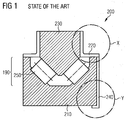
- Figure 1 shows a schematically drawing of a part of a state of the art bearing system for a rotor housing for a generator with an outer rotor according to an exemplary embodiment of the invention.
- PWM inverters variable frequency drives - VFD's
- VFD's induce voltage onto the shaft of the driven motor which may cause pitting, fluting and finally bearing and motor failure.
- a single month's wait for parts is unrealistically short considering the worldwide shortage of bearings and other key components.
- On top of lost revenue is the cost of repairing failed bearings (new bearings, labor, slip rings, and other parts) but also enormous expense of renting and transporting the large crane needed for many repairs must be accounted for.
- Bearing currents caused by stator-to-rotor capacitive coupling must be diverted from the shaft by providing a least resistance path to ground other than the bearing themselves.
- fiberglass laminates are used to isolate bearing from shaft induced voltage.
- Fiber glass laminates may act as an electrical insulation element 220 and may be a good insulation for direct current DC and low frequency current to prevent electric fields from entering the bearing, but it is not useful for high and very high frequency currents, as the capacitance impedance decreases as the current frequency increases.
- an isolated bearing layer can be construed as a resistor and a capacitor in parallel connection.
- the choice of the insulation material depends on the electrical resistance, whereas for high frequency alternating current, such as a frequency converter, the capacitance is decisive. Therefore, the method that provides the best protection depends on the machine design. In order to ensure a good insulation, the electrical resistance should be high and therefore the capacitance as low as possible.
- VFD Variable Frequency Drives
- IGBTs insulated gate bipolar transistors
- Shaft grounding brushes are used to ground stray currents, but primarily use to ground DC and low frequency AC.
- figure 1 shows a part of a state of the art bearing system 200 for a generator with an outer rotor for a rotor housing of a wind turbine, the bearing system 200 comprising an inner bearing ring, an outer bearing ring, a first electrical insulation element 220, a second electrical insulation element 240 and a bearing 190 with a plurality of roller elements 250.
- the first electrical insulation element 220 is arranged around the inner bearing ring 210 in order to provide an electrical shielding to the inner of the bearing system 200.
- the second electrical insulation element 240 is arranged at an outer side of the bearing system 200 in order to provide an electrical shielding to the inner of the bearing system 200.
- the circles depicted with "X" and "Y" identify specific portions of the bearing system 200. In accordance with embodiments of the invention described hereinafter with reference to figure 9 these portions are modified.
- Figure 2 shows a schematically three dimensional drawing of a proposed rotor housing for a generator with an outer rotor according to an exemplary embodiment of the invention.
- Figure 2 shows a rotor housing 100 for a generator with an outer rotor, the rotor housing 100 comprising a support structure 110, wherein the support structure 110 is cylindrical shaped, a front structure 120, a ring 130 and an electrical insulation element 140 (not shown in fig. 2 , see fig. 5 ).
- the ring 130 and the front structure 120 are attached together at an inner side 121 of the front structure 120 in a horizontal plane forming a front part 150 of the rotor housing 100 (see fig. 3 ).
- the support structure 110 is attached to the front structure 120 at a front end of the support structure 110 forming a side part 160 of the rotor housing 100 (see fig. 5 ).
- the electrical insulation element 140 is arranged between the front part 150 (see fig.3 ) of the rotor housing 100 and the side part 160 of the rotor housing 100.
- the rotor housing 100 is made of segmented rotor housing parts 111.
- Figure 3 shows a schematically three dimensional drawing of a proposed front structure and a ring for a rotor housing as shown in figure 2 according to an exemplary embodiment of the invention.
- the ring 130 and the front structure 120 are attached together at an inner side 121 of the front structure 120 in a horizontal plane forming the front part 150 of the rotor housing 100.
- FIG 4 shows a schematic drawing of a proposed segmented front structure and a ring with an electrical insulation element for a rotor housing as shown in figure 2 according to an exemplary embodiment of the invention.
- the front structure 120 is made of segmented front structure parts 122 and comprises an electrical insulation element 140 (see fig. 5 ).
- a cut-out VI is shown, which will be illustrated in more detail in figure 6 .
- a cutting plane V is shown, which will be illustrated in figure 5 .
- Figure 5 shows a schematic drawing of an inner side view V of a part of the proposed front structure as shown in figure 4 and a part of the proposed support structure as shown in figure 2 with an electrical insulation element according to an exemplary embodiment of the invention.
- the electrical insulation element 140 is arranged between the front part 150 of the rotor housing 100 and the side part 160 of the rotor housing 100.
- the electrical insulation element 140 is mounted on the support structure 110 and screwed to the front structure.
- Figure 6 shows a schematically more detailed drawing of a part VI of the proposed segmented front structure as shown in figure 4 with an electrical insulation element according to an exemplary embodiment of the invention.
- the detailed view VI of figure 6 illustrates the electrical insulation element 140 being attached to the front structure 120 by means of bolts.
- the electrical insulation element 140 is arranged between the front part 150 of the rotor housing 100 and the side part 160 of the rotor housing 100 as shown in figure 5 by means of providing a reversible connection, preferably by means of bolting or screwing.
- Figure 7 shows a three dimensional drawing and a scope view of a proposed electrical insulation element as shown in figure 6 according to an exemplary embodiment of the invention.
- a part of the electrical insulation element 140 is shown and the scope A of the electrical insulation element 140 is shown in a magnified view in more detail.
- the electrical insulation element 140 comprises a plurality of holes for bolts, screws or the like, for fixing the electrical insulation element 140 to the front structure 120 as shown for example in figure 4 .
- Figure 8 shows a schematic drawing of an inner side view of a proposed rotor housing as shown in figure 2 with an electrical insulation element, a foil and a discharging element according to an exemplary embodiment of the invention.
- a first turbine element 10 which is partially located outside of the nacelle, like for example a hub, may be fixed to the outer bearing ring 230. Between the outer bearing ring 230 and the first turbine element 10, the first electrical insulation element 220 is interposed. The first electrical insulation element 220 is mounted to the surface of the outer bearing ring 230.
- the outer bearing ring 230 has an outer surface to which a first turbine element 10 of the wind turbine is coupleable.
- the first turbine element 10 is not in direct contact with the outer bearing ring 230 but is separated from the outer bearing ring 230 by the thickness of the first electrical insulation element 220.
- the first turbine element 10 is electrically isolated from the outer bearing ring 230.
- a further first turbine element 11, which is completely located inside the nacelle, like for example a rotor of a generator, may be additionally attached to the outer bearing ring 230.
- the further first turbine element 11 is not in direct contact with the first turbine element 10.
- An electrical isolation is provided because an electrical path between the first turbine element 10 and the further first turbine element 11 is interrupted by the first electrical insulation element 220 and by an air gap between the first turbine element 10 and the further first turbine element 11.
- the electrical insulation elements 220,240 ensure that forces can be transferred between the respective bearing ring 210, 230 and the respective turbine element 10, 11, 20, 21. Therefore, the electrical isolated ring 130 may be formed sufficiently robust for withstanding the transmitted forces. Specifically, the entire wind turbine loads needs to be transferred from the turbine element 10, 11, 20, 21 through the isolating material to the bearing ring 230, 240 and vice versa.
- Figure 9 shows two embodiments of the invention with respect to the portions "X” and “Y” depicted in figure 1 .
- the two left subfigures represent a first embodiment of the portions “X” and “Y”.
- the two right subfigures represent a second embodiment of the portions “X” and “Y”.
- the second embodiment is a further development of the first embodiment.
- the bearing system 200 comprises an inner bearing ring 210 (not shown in fig. 9 ), an outer bearing ring 230 (not shown in fig. 9 ), a first electrical insulation element 220, a second electrical insulation element 240, a plurality of roller elements 250, a first metal element 261, and a second metal element 262.
- the inner bearing ring 210 (not shown in fig. 9 ) is surrounded by the plurality of roller elements 250.
- the plurality of roller elements 250 is surrounded by the outer bearing ring 230 (not shown in fig. 9 ).
- the first electrical insulation element 220 comprises the first metal element 261.
- the second electrical insulation element 240 comprises the second metal element 262.
- the first electrical insulation element 220 is arranged around the outer bearing ring 230 in order to provide an electrical shielding to the outer of the bearing system 200.
- the second electrical insulation element 240 is arranged around the inner bearing ring 210 in order to provide an electrical shielding to the inner of the bearing system 200.
- the plurality of roller elements 250 form a bearing 190 (not shown in fig. 9 ).
- the bearing system 200 further comprises a third metal element 263, and a fourth metal element 264.
- the third metal element 263 is arranged at a first side 221 of the first electrical insulation element 220 in order to provide an additional electrical shielding to the outer of the bearing system 200.
- the fourth metal element 264 is arranged at a first side 241 of the second electrical insulation element 240 in order to provide the additional electrical shielding to the inner of the bearing system 200.
- the first metal element 261 is arranged at least partially around the first electrical insulation element 220.
- the first metal element 261 and the third metal element 263 are arranged at opposite sides of the first electrical insulation element 220.
- the second metal element 262 is arranged at least partially around the second electrical insulation element 240.
- the second metal element 262 and the fourth metal element 264 are arranged at opposite sides of the second electrical insulation element 240.
- the first electrical insulation element 220 and the second electrical insulation element 240 each comprise a glass fiber laminates 222, 242.
- this insulation structure prevents an intrusion of electromagnetic fields generated by frequencies equal or larger than 10 MHz into the respective electrical insulation element 220, 240 and therefore also prevents intrusion of these electromagnetic fields into the bearing 190 (not shown in fig. 9 ), which means into the inner of the bearing system 200 (not shown in fig. 9 ). Therefore, the introduced novel bearing insulation material may efficiently prevent an intrusion of DC and low frequency current as well as high and very high frequency current into the bearing oil film which may cause a machine breakdown.
- Such an electrical insulation element 220 may be shielded with a metallic mesh 223, 243 designed to prevent an intrusion of electromagnetic frequencies around 10MHz and above.
- the metallic mesh 223, 243 may also be grounded externally.
- a metallic mesh 223, 243 (see figs. 10, 11 ) acting as a shield may even be placed in between such a respective electrical insulation element 220, 240 as a sandwich and be molded for example with resin.
- such a respective electrical insulation element 220, 240 may be coated with a conductive electromagnetic shielding coating. If for example, fiber glass laminates are used as such a respective electrical insulation element 220, 240, the surface of the fiber glass laminates should be treated to make it compatible to the electromagnetic shielding coating, to prevent the coating from peeling off.
- the fiber glass insulation thickness may be reduced as the high frequency current blocking ability of the bearing system will no longer depend on the capacitive impedance of the fiber glass, but instead this will be achieved by an electromagnetic wave shielding mechanism.
- a conductive electromagnetic shielding coating may also be used on the stator surface and/or rotor surface to reduce a high frequency coupling between the stator and the rotor.
- Figure 10 shows a schematically drawing of a part of a proposed ring as shown in figures 2, 3 and 4 of a proposed rotor housing as shown in figure 2 .
- Figure 10 further shows an inner side view of a sandwich structure with a mesh in a glass fiber laminates and a glass fiber laminates with a conductive electromagnetic shielding for the proposed bearing system in the ring according to an exemplary embodiment of the invention.
- the ring 130 comprises a mesh 223, 243 designed in order to prevent intrusion of electromagnetic fields generated by high frequency current into the ring 130.
- the mesh 223, 243 comprises a metallic element, and more preferably the mesh 223, 243 prevents intrusion of electromagnetic fields generated by high frequency current equal or larger than 10 MHz into the ring 130.
- the mesh 223, 243 is sandwiched between a respective first part 2221, 2421 of the respective glass fiber laminates 222, 242 and a respective second part 2222, 2422 of the respective glass fiber laminates 222, 242.
- the respective glass fiber laminates 222, 242 comprises a conductive electromagnetic shielding coating 224, 244.
- Figure 11 shows a schematically drawing of an inner side view of a sandwich structure with a glass fiber laminates in a mesh for the proposed ring according to an exemplary embodiment of the invention.
- the ring 130 (see fig. 10 ) comprises an upper mesh 223 and a lower mesh 243, both designed in order to prevent intrusion of electromagnetic fields generated by high frequency current into the ring 130.
- the glass fiber laminates 222, 242 is sandwiched between an upper mesh 223 and a lower mesh 243. Therefore, the sandwich structure shown in figure 11 may act as an alternative solution to the sandwich structure shown in figure 10 .
- attachment may comprise bolting, riveting, welding or any other bonding of two materials, depending of the use of the materials and/or parts attached to each other. Where possible and useful, welding, bolting or riveting may be substituted by each other.
- the proposed invention may also lead to the use of an electrically insulating element arranged in the rotor housing of the generator.
- the electrically insulating element should be able to fit onto a rotor having at least a diameter of 2.5 to 6.5 meter and above and at the same time the layout of the electrically insulating element has to able to withstand occurring mechanical forces in the rotor construction.
Landscapes
- Engineering & Computer Science (AREA)
- General Engineering & Computer Science (AREA)
- Mechanical Engineering (AREA)
- Life Sciences & Earth Sciences (AREA)
- Sustainable Development (AREA)
- Sustainable Energy (AREA)
- Chemical & Material Sciences (AREA)
- Combustion & Propulsion (AREA)
- Rolling Contact Bearings (AREA)
- Motor Or Generator Frames (AREA)
Claims (7)
- Système de roulement (200) pour une éolienne avec un générateur avec un rotor extérieur, préférablement pour un générateur avec un rotor extérieur pour un logement de rotor d'une éolienne, le système de roulement (200) comprenantune bague intérieure (210) de roulement,une bague extérieure (230) de roulement,un premier élément (220) d'isolation électrique,un deuxième élément (240) d'isolation électrique,une pluralité d'éléments roulants (250),un premier élément métallique (261), etun deuxième élément métallique (262), dans lequel les éléments roulants (250) sont agencés dans un volume intérieur entre la bague intérieure (210) de roulement et la bague extérieure (230) de roulement,le premier élément (220) d'isolation électrique comprend le premier élément métallique (261),
le deuxième élément (240) d'isolation électrique comprend le deuxième élément métallique (262),
le premier élément (220) d'isolation électrique est agencé au moins partiellement autour de la bague intérieure (210) de roulement afin de fournir une protection électrique pour l'intérieur du système de roulement (200), et
le deuxième élément (240) d'isolation électrique est agencé au moins partiellement autour de la bague extérieure (230) de roulement afin de fournir une protection électrique pour l'intérieur du système de roulement (200). - Système de roulement (200) selon la revendication précédente 1, dans lequel
le premier élément métallique (261) est agencé sur un côté du premier élément (220) d'isolation électrique, et
le deuxième élément métallique (262) est agencé sur un côté du deuxième élément (240) d'isolation électrique. - Système de roulement (200) selon la revendication précédente 2, comprenant en outreun troisième élément métallique (263), et/ouun quatrième élément métallique (264), dans lequelle premier élément métallique (261) et le troisième élément métallique (263) sont agencés sur des côtés opposés du premier élément (220) d'isolation électrique, et
le deuxième élément métallique (262) et le quatrième élément métallique (264) sont agencés sur des côtés opposés du deuxième élément (240) d'isolation électrique. - Système de roulement (200) selon l'une quelconque des revendications précédentes 1 à 3, dans lequel le premier élément (220) d'isolation électrique et le deuxième élément (240) d'isolation électrique comprennent chacun des stratifiés de fibre de verre (222, 242).
- Système de roulement (200) selon la revendication précédente 4, dans lequel
les stratifiés de fibre de verre (222, 242) comprennent un maillage (223, 243) conçu pour prévenir une intrusion de champs électromagnétiques générés par des fréquences dans l'élément (220, 240) d'isolation électrique respectif, préférablement le maillage (223, 243) comprenant un élément métallique, et plus préférablement le maillage prévenant une intrusion de champs électromagnétiques générés par des fréquences égales ou supérieures à 10 MHz dans l'élément (220, 240) d'isolation électrique respectif. - Système de roulement (200) selon la revendication précédente 5, dans lequel
le maillage (223, 243) est pris en sandwich entre une première partie (2221, 2421) respective des stratifiés de fibre de verre (222, 242) respectifs et une deuxième partie (2222, 2422) respective des stratifiés de fibre de verre (222, 242) respectifs. - Système de roulement (200) selon l'une quelconque des revendications précédentes 4 à 6, dans lequel les stratifiés de fibre de verre (222, 242) respectifs comprennent un revêtement de protection électromagnétique conducteur (224, 244).
Priority Applications (4)
| Application Number | Priority Date | Filing Date | Title |
|---|---|---|---|
| EP14171362.8A EP2952737B1 (fr) | 2014-06-05 | 2014-06-05 | Isolation de palier |
| DK14171362.8T DK2952737T3 (en) | 2014-06-05 | 2014-06-05 | rent Insulation |
| US14/613,578 US9482283B2 (en) | 2014-06-05 | 2015-02-04 | Bearing insulation |
| CN201510302172.9A CN105322697B (zh) | 2014-06-05 | 2015-06-05 | 轴承绝缘 |
Applications Claiming Priority (1)
| Application Number | Priority Date | Filing Date | Title |
|---|---|---|---|
| EP14171362.8A EP2952737B1 (fr) | 2014-06-05 | 2014-06-05 | Isolation de palier |
Publications (2)
| Publication Number | Publication Date |
|---|---|
| EP2952737A1 EP2952737A1 (fr) | 2015-12-09 |
| EP2952737B1 true EP2952737B1 (fr) | 2016-08-31 |
Family
ID=50943096
Family Applications (1)
| Application Number | Title | Priority Date | Filing Date |
|---|---|---|---|
| EP14171362.8A Not-in-force EP2952737B1 (fr) | 2014-06-05 | 2014-06-05 | Isolation de palier |
Country Status (2)
| Country | Link |
|---|---|
| EP (1) | EP2952737B1 (fr) |
| DK (1) | DK2952737T3 (fr) |
Families Citing this family (1)
| Publication number | Priority date | Publication date | Assignee | Title |
|---|---|---|---|---|
| GB2535481A (en) * | 2015-02-17 | 2016-08-24 | Skf Ab | Electrically insulated bearing |
Family Cites Families (3)
| Publication number | Priority date | Publication date | Assignee | Title |
|---|---|---|---|---|
| JP2008202782A (ja) * | 2007-01-26 | 2008-09-04 | Jtekt Corp | 転がり軸受装置 |
| EP2620643A1 (fr) * | 2012-01-27 | 2013-07-31 | Siemens Aktiengesellschaft | Support de joint composite pour un roulement principal de commande directe d'une éolienne |
| DE102012221739B4 (de) * | 2012-11-28 | 2022-02-17 | Aktiebolaget Skf | Teil einer Windenergieanlage |
-
2014
- 2014-06-05 EP EP14171362.8A patent/EP2952737B1/fr not_active Not-in-force
- 2014-06-05 DK DK14171362.8T patent/DK2952737T3/en active
Also Published As
| Publication number | Publication date |
|---|---|
| EP2952737A1 (fr) | 2015-12-09 |
| DK2952737T3 (en) | 2016-12-19 |
Similar Documents
| Publication | Publication Date | Title |
|---|---|---|
| US9482283B2 (en) | Bearing insulation | |
| EP1996815B1 (fr) | Systeme de protection pour generateur electrique, eolienne et son utilisation | |
| CN110168877B (zh) | 电机定子的电隔离安装 | |
| US20120219420A1 (en) | Lightning protection for a nacelle of a wind turbine | |
| US20130038182A1 (en) | Inverter-driven dynamo electric machine and system, bearing, and end bracket for same | |
| US8063522B2 (en) | Generator rotor ground bushing | |
| EP3571399B1 (fr) | Éolienne comprenant un système de mise à la terre pour transférer un courant de foudre et pour fournir un blindage electromagnétique | |
| EP3588745B1 (fr) | Ensemble stator segmenté comportant des connexions électriques flexibles, générateur et turbine éolienne comportant un tel ensemble stator | |
| EP2952737B1 (fr) | Isolation de palier | |
| WO2018113865A1 (fr) | Montage d'isolation électrique de stator de machine électrique | |
| EP2456049A1 (fr) | Agencement d'une tige conductrice raccordée à une plaque conductrice et son procédé de démontage | |
| US8513541B2 (en) | Method of blocking electro-magnetic interference (EMI) in an electric machine and apparatus | |
| EP2806536A1 (fr) | Machine électrique | |
| EP2621056A1 (fr) | Ensemble de rotor de générateur d'éolienne | |
| CN116357521B (zh) | 一种发电组合体及其制作工艺 | |
| US20130319728A1 (en) | Apparatus and method to insulate a shaft | |
| EP2822157B1 (fr) | Réduction des courants de paliers dans un générateur de turbine éolienne | |
| EP2831983B1 (fr) | Machine électrique et procédé d'assemblage | |
| WO2021156029A1 (fr) | Segment de stator, stator, éolienne et procédé de fabrication de segment de stator | |
| CN103023191A (zh) | 隔爆型自然冷却异步电机 | |
| DE102014210788A1 (de) | Lagerisolierung | |
| US20250035184A1 (en) | Flywheel device for a syncronous condenser | |
| WO2005119857A1 (fr) | Dispositif de transfert de courant pour eolienne | |
| US20250279703A1 (en) | Segmented rotary transformer having a large diameter | |
| CN203843440U (zh) | 一种变位动力装置 |
Legal Events
| Date | Code | Title | Description |
|---|---|---|---|
| PUAI | Public reference made under article 153(3) epc to a published international application that has entered the european phase |
Free format text: ORIGINAL CODE: 0009012 |
|
| AK | Designated contracting states |
Kind code of ref document: A1 Designated state(s): AL AT BE BG CH CY CZ DE DK EE ES FI FR GB GR HR HU IE IS IT LI LT LU LV MC MK MT NL NO PL PT RO RS SE SI SK SM TR |
|
| AX | Request for extension of the european patent |
Extension state: BA ME |
|
| REG | Reference to a national code |
Ref country code: DE Ref legal event code: R079 Ref document number: 602014003352 Country of ref document: DE Free format text: PREVIOUS MAIN CLASS: F03D0011000000 Ipc: F16C0033000000 |
|
| 17P | Request for examination filed |
Effective date: 20160107 |
|
| RBV | Designated contracting states (corrected) |
Designated state(s): AL AT BE BG CH CY CZ DE DK EE ES FI FR GB GR HR HU IE IS IT LI LT LU LV MC MK MT NL NO PL PT RO RS SE SI SK SM TR |
|
| RIC1 | Information provided on ipc code assigned before grant |
Ipc: F16C 33/00 20060101AFI20160203BHEP Ipc: F16C 19/52 20060101ALI20160203BHEP Ipc: F03D 80/00 20160101ALI20160203BHEP Ipc: F16C 35/07 20060101ALI20160203BHEP |
|
| GRAP | Despatch of communication of intention to grant a patent |
Free format text: ORIGINAL CODE: EPIDOSNIGR1 |
|
| INTG | Intention to grant announced |
Effective date: 20160311 |
|
| GRAS | Grant fee paid |
Free format text: ORIGINAL CODE: EPIDOSNIGR3 |
|
| GRAA | (expected) grant |
Free format text: ORIGINAL CODE: 0009210 |
|
| AK | Designated contracting states |
Kind code of ref document: B1 Designated state(s): AL AT BE BG CH CY CZ DE DK EE ES FI FR GB GR HR HU IE IS IT LI LT LU LV MC MK MT NL NO PL PT RO RS SE SI SK SM TR |
|
| REG | Reference to a national code |
Ref country code: CH Ref legal event code: EP Ref country code: GB Ref legal event code: FG4D |
|
| REG | Reference to a national code |
Ref country code: IE Ref legal event code: FG4D |
|
| REG | Reference to a national code |
Ref country code: AT Ref legal event code: REF Ref document number: 825266 Country of ref document: AT Kind code of ref document: T Effective date: 20161015 |
|
| REG | Reference to a national code |
Ref country code: DE Ref legal event code: R096 Ref document number: 602014003352 Country of ref document: DE |
|
| REG | Reference to a national code |
Ref country code: DK Ref legal event code: T3 Effective date: 20161218 |
|
| REG | Reference to a national code |
Ref country code: LT Ref legal event code: MG4D |
|
| REG | Reference to a national code |
Ref country code: NL Ref legal event code: MP Effective date: 20160831 |
|
| REG | Reference to a national code |
Ref country code: AT Ref legal event code: MK05 Ref document number: 825266 Country of ref document: AT Kind code of ref document: T Effective date: 20160831 |
|
| PG25 | Lapsed in a contracting state [announced via postgrant information from national office to epo] |
Ref country code: FI Free format text: LAPSE BECAUSE OF FAILURE TO SUBMIT A TRANSLATION OF THE DESCRIPTION OR TO PAY THE FEE WITHIN THE PRESCRIBED TIME-LIMIT Effective date: 20160831 Ref country code: NO Free format text: LAPSE BECAUSE OF FAILURE TO SUBMIT A TRANSLATION OF THE DESCRIPTION OR TO PAY THE FEE WITHIN THE PRESCRIBED TIME-LIMIT Effective date: 20161130 Ref country code: LT Free format text: LAPSE BECAUSE OF FAILURE TO SUBMIT A TRANSLATION OF THE DESCRIPTION OR TO PAY THE FEE WITHIN THE PRESCRIBED TIME-LIMIT Effective date: 20160831 Ref country code: RS Free format text: LAPSE BECAUSE OF FAILURE TO SUBMIT A TRANSLATION OF THE DESCRIPTION OR TO PAY THE FEE WITHIN THE PRESCRIBED TIME-LIMIT Effective date: 20160831 Ref country code: HR Free format text: LAPSE BECAUSE OF FAILURE TO SUBMIT A TRANSLATION OF THE DESCRIPTION OR TO PAY THE FEE WITHIN THE PRESCRIBED TIME-LIMIT Effective date: 20160831 |
|
| PG25 | Lapsed in a contracting state [announced via postgrant information from national office to epo] |
Ref country code: LV Free format text: LAPSE BECAUSE OF FAILURE TO SUBMIT A TRANSLATION OF THE DESCRIPTION OR TO PAY THE FEE WITHIN THE PRESCRIBED TIME-LIMIT Effective date: 20160831 Ref country code: SE Free format text: LAPSE BECAUSE OF FAILURE TO SUBMIT A TRANSLATION OF THE DESCRIPTION OR TO PAY THE FEE WITHIN THE PRESCRIBED TIME-LIMIT Effective date: 20160831 Ref country code: ES Free format text: LAPSE BECAUSE OF FAILURE TO SUBMIT A TRANSLATION OF THE DESCRIPTION OR TO PAY THE FEE WITHIN THE PRESCRIBED TIME-LIMIT Effective date: 20160831 Ref country code: NL Free format text: LAPSE BECAUSE OF FAILURE TO SUBMIT A TRANSLATION OF THE DESCRIPTION OR TO PAY THE FEE WITHIN THE PRESCRIBED TIME-LIMIT Effective date: 20160831 Ref country code: GR Free format text: LAPSE BECAUSE OF FAILURE TO SUBMIT A TRANSLATION OF THE DESCRIPTION OR TO PAY THE FEE WITHIN THE PRESCRIBED TIME-LIMIT Effective date: 20161201 Ref country code: AT Free format text: LAPSE BECAUSE OF FAILURE TO SUBMIT A TRANSLATION OF THE DESCRIPTION OR TO PAY THE FEE WITHIN THE PRESCRIBED TIME-LIMIT Effective date: 20160831 |
|
| PG25 | Lapsed in a contracting state [announced via postgrant information from national office to epo] |
Ref country code: RO Free format text: LAPSE BECAUSE OF FAILURE TO SUBMIT A TRANSLATION OF THE DESCRIPTION OR TO PAY THE FEE WITHIN THE PRESCRIBED TIME-LIMIT Effective date: 20160831 Ref country code: EE Free format text: LAPSE BECAUSE OF FAILURE TO SUBMIT A TRANSLATION OF THE DESCRIPTION OR TO PAY THE FEE WITHIN THE PRESCRIBED TIME-LIMIT Effective date: 20160831 |
|
| PG25 | Lapsed in a contracting state [announced via postgrant information from national office to epo] |
Ref country code: BE Free format text: LAPSE BECAUSE OF FAILURE TO SUBMIT A TRANSLATION OF THE DESCRIPTION OR TO PAY THE FEE WITHIN THE PRESCRIBED TIME-LIMIT Effective date: 20160831 Ref country code: PT Free format text: LAPSE BECAUSE OF FAILURE TO SUBMIT A TRANSLATION OF THE DESCRIPTION OR TO PAY THE FEE WITHIN THE PRESCRIBED TIME-LIMIT Effective date: 20170102 Ref country code: SM Free format text: LAPSE BECAUSE OF FAILURE TO SUBMIT A TRANSLATION OF THE DESCRIPTION OR TO PAY THE FEE WITHIN THE PRESCRIBED TIME-LIMIT Effective date: 20160831 Ref country code: PL Free format text: LAPSE BECAUSE OF FAILURE TO SUBMIT A TRANSLATION OF THE DESCRIPTION OR TO PAY THE FEE WITHIN THE PRESCRIBED TIME-LIMIT Effective date: 20160831 Ref country code: CZ Free format text: LAPSE BECAUSE OF FAILURE TO SUBMIT A TRANSLATION OF THE DESCRIPTION OR TO PAY THE FEE WITHIN THE PRESCRIBED TIME-LIMIT Effective date: 20160831 Ref country code: BG Free format text: LAPSE BECAUSE OF FAILURE TO SUBMIT A TRANSLATION OF THE DESCRIPTION OR TO PAY THE FEE WITHIN THE PRESCRIBED TIME-LIMIT Effective date: 20161130 Ref country code: SK Free format text: LAPSE BECAUSE OF FAILURE TO SUBMIT A TRANSLATION OF THE DESCRIPTION OR TO PAY THE FEE WITHIN THE PRESCRIBED TIME-LIMIT Effective date: 20160831 |
|
| REG | Reference to a national code |
Ref country code: DE Ref legal event code: R097 Ref document number: 602014003352 Country of ref document: DE |
|
| REG | Reference to a national code |
Ref country code: FR Ref legal event code: PLFP Year of fee payment: 4 |
|
| PG25 | Lapsed in a contracting state [announced via postgrant information from national office to epo] |
Ref country code: IT Free format text: LAPSE BECAUSE OF FAILURE TO SUBMIT A TRANSLATION OF THE DESCRIPTION OR TO PAY THE FEE WITHIN THE PRESCRIBED TIME-LIMIT Effective date: 20160831 |
|
| PLBE | No opposition filed within time limit |
Free format text: ORIGINAL CODE: 0009261 |
|
| STAA | Information on the status of an ep patent application or granted ep patent |
Free format text: STATUS: NO OPPOSITION FILED WITHIN TIME LIMIT |
|
| 26N | No opposition filed |
Effective date: 20170601 |
|
| PG25 | Lapsed in a contracting state [announced via postgrant information from national office to epo] |
Ref country code: SI Free format text: LAPSE BECAUSE OF FAILURE TO SUBMIT A TRANSLATION OF THE DESCRIPTION OR TO PAY THE FEE WITHIN THE PRESCRIBED TIME-LIMIT Effective date: 20160831 |
|
| REG | Reference to a national code |
Ref country code: CH Ref legal event code: NV Representative=s name: SIEMENS SCHWEIZ AG, CH Ref country code: CH Ref legal event code: PCOW Free format text: NEW ADDRESS: WERNER-VON-SIEMENS-STRASSE 1, 80333 MUENCHEN (DE) |
|
| PG25 | Lapsed in a contracting state [announced via postgrant information from national office to epo] |
Ref country code: MC Free format text: LAPSE BECAUSE OF FAILURE TO SUBMIT A TRANSLATION OF THE DESCRIPTION OR TO PAY THE FEE WITHIN THE PRESCRIBED TIME-LIMIT Effective date: 20160831 |
|
| REG | Reference to a national code |
Ref country code: CH Ref legal event code: PL |
|
| REG | Reference to a national code |
Ref country code: IE Ref legal event code: MM4A |
|
| PG25 | Lapsed in a contracting state [announced via postgrant information from national office to epo] |
Ref country code: LI Free format text: LAPSE BECAUSE OF NON-PAYMENT OF DUE FEES Effective date: 20170630 Ref country code: LU Free format text: LAPSE BECAUSE OF NON-PAYMENT OF DUE FEES Effective date: 20170605 Ref country code: IE Free format text: LAPSE BECAUSE OF NON-PAYMENT OF DUE FEES Effective date: 20170605 Ref country code: CH Free format text: LAPSE BECAUSE OF NON-PAYMENT OF DUE FEES Effective date: 20170630 |
|
| REG | Reference to a national code |
Ref country code: FR Ref legal event code: PLFP Year of fee payment: 5 |
|
| PGFP | Annual fee paid to national office [announced via postgrant information from national office to epo] |
Ref country code: FR Payment date: 20180614 Year of fee payment: 5 |
|
| PG25 | Lapsed in a contracting state [announced via postgrant information from national office to epo] |
Ref country code: MT Free format text: LAPSE BECAUSE OF NON-PAYMENT OF DUE FEES Effective date: 20170605 |
|
| PG25 | Lapsed in a contracting state [announced via postgrant information from national office to epo] |
Ref country code: AL Free format text: LAPSE BECAUSE OF FAILURE TO SUBMIT A TRANSLATION OF THE DESCRIPTION OR TO PAY THE FEE WITHIN THE PRESCRIBED TIME-LIMIT Effective date: 20160831 |
|
| PGFP | Annual fee paid to national office [announced via postgrant information from national office to epo] |
Ref country code: GB Payment date: 20180614 Year of fee payment: 5 Ref country code: DE Payment date: 20180820 Year of fee payment: 5 |
|
| PGFP | Annual fee paid to national office [announced via postgrant information from national office to epo] |
Ref country code: DK Payment date: 20180620 Year of fee payment: 5 |
|
| PG25 | Lapsed in a contracting state [announced via postgrant information from national office to epo] |
Ref country code: HU Free format text: LAPSE BECAUSE OF FAILURE TO SUBMIT A TRANSLATION OF THE DESCRIPTION OR TO PAY THE FEE WITHIN THE PRESCRIBED TIME-LIMIT; INVALID AB INITIO Effective date: 20140605 |
|
| PG25 | Lapsed in a contracting state [announced via postgrant information from national office to epo] |
Ref country code: CY Free format text: LAPSE BECAUSE OF FAILURE TO SUBMIT A TRANSLATION OF THE DESCRIPTION OR TO PAY THE FEE WITHIN THE PRESCRIBED TIME-LIMIT Effective date: 20160831 |
|
| PG25 | Lapsed in a contracting state [announced via postgrant information from national office to epo] |
Ref country code: MK Free format text: LAPSE BECAUSE OF FAILURE TO SUBMIT A TRANSLATION OF THE DESCRIPTION OR TO PAY THE FEE WITHIN THE PRESCRIBED TIME-LIMIT Effective date: 20160831 |
|
| REG | Reference to a national code |
Ref country code: DE Ref legal event code: R119 Ref document number: 602014003352 Country of ref document: DE |
|
| REG | Reference to a national code |
Ref country code: DK Ref legal event code: EBP Effective date: 20190630 |
|
| GBPC | Gb: european patent ceased through non-payment of renewal fee |
Effective date: 20190605 |
|
| PG25 | Lapsed in a contracting state [announced via postgrant information from national office to epo] |
Ref country code: TR Free format text: LAPSE BECAUSE OF FAILURE TO SUBMIT A TRANSLATION OF THE DESCRIPTION OR TO PAY THE FEE WITHIN THE PRESCRIBED TIME-LIMIT Effective date: 20160831 |
|
| PG25 | Lapsed in a contracting state [announced via postgrant information from national office to epo] |
Ref country code: GB Free format text: LAPSE BECAUSE OF NON-PAYMENT OF DUE FEES Effective date: 20190605 Ref country code: DE Free format text: LAPSE BECAUSE OF NON-PAYMENT OF DUE FEES Effective date: 20200101 |
|
| PG25 | Lapsed in a contracting state [announced via postgrant information from national office to epo] |
Ref country code: FR Free format text: LAPSE BECAUSE OF NON-PAYMENT OF DUE FEES Effective date: 20190630 |
|
| PG25 | Lapsed in a contracting state [announced via postgrant information from national office to epo] |
Ref country code: DK Free format text: LAPSE BECAUSE OF NON-PAYMENT OF DUE FEES Effective date: 20190630 Ref country code: IS Free format text: LAPSE BECAUSE OF FAILURE TO SUBMIT A TRANSLATION OF THE DESCRIPTION OR TO PAY THE FEE WITHIN THE PRESCRIBED TIME-LIMIT Effective date: 20161231 |