EP2952764A1 - Lager mit magnetischer fluiddichtung - Google Patents
Lager mit magnetischer fluiddichtung Download PDFInfo
- Publication number
- EP2952764A1 EP2952764A1 EP15170607.4A EP15170607A EP2952764A1 EP 2952764 A1 EP2952764 A1 EP 2952764A1 EP 15170607 A EP15170607 A EP 15170607A EP 2952764 A1 EP2952764 A1 EP 2952764A1
- Authority
- EP
- European Patent Office
- Prior art keywords
- ring
- bearing
- magnetic fluid
- magnet
- shaped
- Prior art date
- Legal status (The legal status is an assumption and is not a legal conclusion. Google has not performed a legal analysis and makes no representation as to the accuracy of the status listed.)
- Granted
Links
Images




Classifications
-
- F—MECHANICAL ENGINEERING; LIGHTING; HEATING; WEAPONS; BLASTING
- F16—ENGINEERING ELEMENTS AND UNITS; GENERAL MEASURES FOR PRODUCING AND MAINTAINING EFFECTIVE FUNCTIONING OF MACHINES OR INSTALLATIONS; THERMAL INSULATION IN GENERAL
- F16C—SHAFTS; FLEXIBLE SHAFTS; ELEMENTS OR CRANKSHAFT MECHANISMS; ROTARY BODIES OTHER THAN GEARING ELEMENTS; BEARINGS
- F16C33/00—Parts of bearings; Special methods for making bearings or parts thereof
- F16C33/72—Sealings
- F16C33/76—Sealings of ball or roller bearings
- F16C33/762—Sealings of ball or roller bearings by means of a fluid
- F16C33/763—Sealings of ball or roller bearings by means of a fluid retained in the sealing gap
- F16C33/765—Sealings of ball or roller bearings by means of a fluid retained in the sealing gap by a magnetic field
-
- F—MECHANICAL ENGINEERING; LIGHTING; HEATING; WEAPONS; BLASTING
- F16—ENGINEERING ELEMENTS AND UNITS; GENERAL MEASURES FOR PRODUCING AND MAINTAINING EFFECTIVE FUNCTIONING OF MACHINES OR INSTALLATIONS; THERMAL INSULATION IN GENERAL
- F16C—SHAFTS; FLEXIBLE SHAFTS; ELEMENTS OR CRANKSHAFT MECHANISMS; ROTARY BODIES OTHER THAN GEARING ELEMENTS; BEARINGS
- F16C19/00—Bearings with rolling contact, for exclusively rotary movement
- F16C19/02—Bearings with rolling contact, for exclusively rotary movement with bearing balls essentially of the same size in one or more circular rows
- F16C19/04—Bearings with rolling contact, for exclusively rotary movement with bearing balls essentially of the same size in one or more circular rows for radial load mainly
- F16C19/06—Bearings with rolling contact, for exclusively rotary movement with bearing balls essentially of the same size in one or more circular rows for radial load mainly with a single row or balls
-
- F—MECHANICAL ENGINEERING; LIGHTING; HEATING; WEAPONS; BLASTING
- F16—ENGINEERING ELEMENTS AND UNITS; GENERAL MEASURES FOR PRODUCING AND MAINTAINING EFFECTIVE FUNCTIONING OF MACHINES OR INSTALLATIONS; THERMAL INSULATION IN GENERAL
- F16C—SHAFTS; FLEXIBLE SHAFTS; ELEMENTS OR CRANKSHAFT MECHANISMS; ROTARY BODIES OTHER THAN GEARING ELEMENTS; BEARINGS
- F16C33/00—Parts of bearings; Special methods for making bearings or parts thereof
- F16C33/72—Sealings
- F16C33/76—Sealings of ball or roller bearings
- F16C33/78—Sealings of ball or roller bearings with a diaphragm, disc, or ring, with or without resilient members
- F16C33/784—Sealings of ball or roller bearings with a diaphragm, disc, or ring, with or without resilient members mounted to a groove in the inner surface of the outer race and extending toward the inner race
- F16C33/7843—Sealings of ball or roller bearings with a diaphragm, disc, or ring, with or without resilient members mounted to a groove in the inner surface of the outer race and extending toward the inner race with a single annular sealing disc
- F16C33/7846—Sealings of ball or roller bearings with a diaphragm, disc, or ring, with or without resilient members mounted to a groove in the inner surface of the outer race and extending toward the inner race with a single annular sealing disc with a gap between the annular disc and the inner race
-
- F—MECHANICAL ENGINEERING; LIGHTING; HEATING; WEAPONS; BLASTING
- F16—ENGINEERING ELEMENTS AND UNITS; GENERAL MEASURES FOR PRODUCING AND MAINTAINING EFFECTIVE FUNCTIONING OF MACHINES OR INSTALLATIONS; THERMAL INSULATION IN GENERAL
- F16C—SHAFTS; FLEXIBLE SHAFTS; ELEMENTS OR CRANKSHAFT MECHANISMS; ROTARY BODIES OTHER THAN GEARING ELEMENTS; BEARINGS
- F16C33/00—Parts of bearings; Special methods for making bearings or parts thereof
- F16C33/72—Sealings
- F16C33/76—Sealings of ball or roller bearings
- F16C33/78—Sealings of ball or roller bearings with a diaphragm, disc, or ring, with or without resilient members
- F16C33/7889—Sealings of ball or roller bearings with a diaphragm, disc, or ring, with or without resilient members mounted to an inner race and extending toward the outer race
-
- F—MECHANICAL ENGINEERING; LIGHTING; HEATING; WEAPONS; BLASTING
- F16—ENGINEERING ELEMENTS AND UNITS; GENERAL MEASURES FOR PRODUCING AND MAINTAINING EFFECTIVE FUNCTIONING OF MACHINES OR INSTALLATIONS; THERMAL INSULATION IN GENERAL
- F16J—PISTONS; CYLINDERS; SEALINGS
- F16J15/00—Sealings
- F16J15/16—Sealings between relatively-moving surfaces
- F16J15/40—Sealings between relatively-moving surfaces by means of fluid
- F16J15/43—Sealings between relatively-moving surfaces by means of fluid kept in sealing position by magnetic force
Definitions
- the present invention relates to a bearing with a magnetic fluid seal which supports a rotating shaft in a rotatable manner in various power transmission mechanisms, the magnetic fluid seal preventing foreign matter, such as dust and moisture, from intruding into an inner region of the bearing.
- Ball bearings include a plurality of rolling elements (rolling members) arranged in a circumferential direction in a space between an inner ring and an outer ring. The rotational performance of rotating shafts can be increased by using bearings of this type.
- This type of bearing is used as means for supporting a rotating shaft in a drive power transmission mechanism for various drive devices.
- Some drive devices are required to prevent foreign matter, such as dust and moisture, from intruding into an inner region thereof through a bearing section. If foreign matter intrudes into the bearing itself, there will be a problem that the rotational performance will be degraded or abnormal noise will be generated.
- a seal member made of an elastic material may be arranged on the outer periphery of the rotating shaft in the vicinity of the bearing, so that the bearing section is waterproof and dustproof.
- the rotational performance of the rotating shaft is degraded due to the influence of a contact pressure applied by the sealing member made of an elastic material.
- Bearings having magnetic fluid seal mechanisms in which magnetic fluid is used are known structures that prevent foreign matter from intruding into the bearing section without reducing the rotational performance of the rotating shaft.
- PTL 1 discloses a ball bearing in which rolling elements are retained between an outer ring and an inner ring and in which a magnetic member is interposed between the outer ring and the inner ring that rotate relative to each other, the magnetic member being fixed at one side thereof and magnetic fluid being disposed in a seal gap provided at the other side of the magnetic member.
- the magnetic member is disposed between the inner ring and the outer ring so as to block the rolling elements, the magnetic member being fixed at one side thereof and the magnetic fluid being disposed in the seal gap provided at the other side of the magnetic member. Accordingly, the rolling elements are tightly sealed and intrusion of foreign matter into a rolling element section, which affects the rotational performance, is prevented.
- the above-described bearing with the magnetic fluid seal disclosed in PTL 1 provides a sufficient sealing effect for dust and liquid having a relatively high viscosity.
- the sealing effect will not be sufficient for liquid having a low viscosity.
- the dimensional accuracy of the magnetic member is lower than those of components included in the bearing, and therefore the magnetic member easily allows liquid to intrude into the bearing at the fixed side thereof.
- the lower the velocity of the liquid the more easily the liquid intrudes into the rolling element section (in particular, intrusion of seawater leads to a degradation of rotational performance since the seawater that has intruded dries and forms salt crystals).
- it is necessary to accurately control the dimensions of the magnetic member or install additional sealing components. As a result, productivity will be reduced.
- the present invention has been made in light of the above-described problems, and an object of the present invention is to provide a bearing with a magnetic fluid seal which reliably maintains the state in which a rolling element section in the bearing is sealed and which has a structure that ensures high productivity.
- a bearing comprising: an inner ring; an outer ring; a plurality of rolling elements positioned between the inner ring and the outer ring; a ring-shaped magnet positioned between the inner ring and the outer ring at an axially outer side of the plurality of rolling elements and magnetized such that magnetic poles are oriented in an axial direction; a ring-shaped plate arranged so as to be in contact with an axially outer side surface of the ring-shaped magnet; and inner-ring-side magnetic fluid retained at least between the inner ring and the ring-shaped plate, wherein a step is formed in an inner circumferential surface of the outer ring such that a distance between the inner and outer rings is greater at an axially outer side than at an axially inner side, wherein the ring-shaped magnet is attracted to a step surface of the step by a magnetic force, and wherein an axially outer side surface of the plate is retreated such that at least an inner-ring-
- the plate includes a tapered portion being thinner radially inward.
- the outer-ring-side magnetic fluid is arranged between the outer ring and an axially inner side surface of the ring-shaped magnet.
- a gap is formed between an outer peripheral surface of the ring-shaped plate and an inner peripheral surface of the outer ring, and the magnetic fluid is disposed in the gap.
- the ring-shaped magnet is bonded to the ring-shaped plate.
- the bearing further comprises a ring-shaped shield provided on the axially outer side surface of the plate.
- the bearing further comprises a spacer provided between the magnet and the outer ring.
- the spacer is formed of a magnetic member.
- a bearing comprising: an inner ring; an outer ring; a plurality of rolling elements positioned between the inner ring and the outer ring; a ring-shaped magnet positioned between the inner ring and the outer ring at an axially outer side of the plurality of rolling elements and magnetized such that magnetic poles are oriented in an axial direction; a ring-shaped plate arranged so as to be in contact with an axially outer side surface of the ring-shaped magnet; and outer-ring-side magnetic fluid retained at least between the outer ring and the ring-shaped plate, wherein a step is formed in an outer circumferential surface of the inner ring such that a distance between the inner and outer rings is greater at an axially outer side than at an axially inner side, wherein the ring-shaped magnet is attracted to a step surface of the step by a magnetic force, and wherein an axially outer side surface of the plate is retreated such that at least an outer-ring
- the plate includes a tapered portion being thinner radially outward.
- the bearing further comprises inner-ring-side magnetic fluid retained at least between the inner ring and the ring-shaped magnet.
- the inner-ring-side magnetic fluid is arranged between the inner ring and an axially inner side surface of the ring-shaped magnet.
- a gap is formed between an inner peripheral surface of the ring-shaped plate and an outer peripheral surface of the inner ring, and the magnetic fluid is disposed in the gap.
- the ring-shaped magnet is bonded to the ring-shaped plate.
- the bearing further comprises a ring-shaped shield provided on the axially outer side surface of the plate.
- a spacer is provided between the magnet and the inner ring.
- the spacer is formed of a magnetic member.
- a bearing with a magnetic fluid seal wherein a plurality of rolling elements are interposed between an inner ring and an outer ring, and a ring-shaped magnet is arranged at an opening side of the inner and outer rings so as to retain magnetic fluid for sealing the plurality of rolling elements, and wherein the ring-shaped magnet is magnetized such that magnetic poles are oriented in an axial direction
- the bearing comprising: a ring-shaped plate arranged so as to be in contact with an axially outer side surface of the ring-shaped magnet; outer-ring-side magnetic fluid retained at least between the outer ring and the ring-shaped plate; and inner-ring-side magnetic fluid retained at least between the inner ring and the ring-shaped magnet, wherein the ring-shaped plate is press-fitted to the inner ring, and a step gap is formed between the ring-shaped magnet and the step, and wherein the magnetic fluid is disposed in the step gap.
- a bearing with a magnetic fluid seal wherein a plurality of rolling elements are interposed between an inner ring and an outer ring, and a ring-shaped magnet is arranged at an opening side of the inner and outer rings so as to retain magnetic fluid, so that the plurality of rolling elements are sealed, is characterized in that the ring-shaped magnet is magnetized so that magnetic poles are oriented in an axial direction, and the bearing includes a ring-shaped pole plate arranged so as to be in contact with an outer side surface of the ring-shaped magnet in the axial direction; outer-ring-side magnetic fluid retained between the outer ring and the ring-shaped pole plate and/or between the outer ring and the ring-shaped magnet; and inner-ring-side magnetic fluid retained between the inner ring and the ring-shaped pole plate and/or between the inner ring and the ring-shaped magnet.
- the ring-shaped magnet is magnetized so that the magnetic poles are oriented in the axial direction, and the ring-shaped pole plate is arranged so as to be in contact with the outer side surface of the ring-shaped magnet in the axial direction. Therefore, the magnetic fluid (outer-ring-side magnetic fluid) can be retained between the outer ring and the ring-shaped pole plate and/or between the outer ring and the ring-shaped magnet; and the magnetic fluid (inner-ring-side magnetic fluid) can be retained between the inner ring and the ring-shaped pole plate and/or between the inner ring and the ring-shaped magnet.
- the magnetic fluid may be retained in both a gap on the inner peripheral surface of the outer ring and a gap on the outer peripheral surface of the inner ring. Therefore, sufficient sealing effect can be achieved for the rolling elements even when the dimensional accuracy of the ring-shaped magnet is low, and it is not necessary to accurately control the dimensions of the ring-shaped magnet. As a result, the assembly can be facilitated and productivity can be increased.
- the magnetic fluid retained on the inner peripheral surface of the outer ring and the outer peripheral surface of the inner ring may either be provided at only one of the openings at the ends of the bearing or be provided at both of the openings.
- a bearing with a magnetic fluid seal which reliably maintains the state in which a rolling element section in the bearing is sealed and which has a structure that ensures high productivity.
- Figs. 1 and 2 illustrate a bearing with a magnetic fluid seal according to the first embodiment of the present invention.
- Fig. 1 is a sectional view taken in an axial direction
- Fig. 2 is enlarged view of a relevant part in Fig. 1 .
- the bearing with a magnetic fluid seal (hereinafter referred to also as a bearing) 1 may include a cylindrical inner ring 3, a cylindrical outer ring 5 that may surround the inner ring 3, and a plurality of rolling elements (rolling members) 7 that may be interposed between the inner ring 3 and the outer ring 5.
- the rolling elements 7 may be retained by a retainer (retaining member) 8, which may extend in a circumferential direction, and the inner ring 3 and the outer ring 5 may be rotatable relative to each other.
- the inner ring 3, the outer ring 5, and the rolling elements 7 may be made of a magnetic material, such as a chromium stainless steel (SUS440C).
- the retainer 8 may be made of a material having a high corrosion resistance and a high heat resistance, such as a stainless steel (SUS304). It is not necessary that the rolling elements 7 be magnetic members.
- the outer ring 5 may be formed such that an exposed end surface 5a thereof is flush with (or substantially flush with) an exposed end surface 3a of the inner ring 3.
- the outer ring 5 may be longer than the inner ring 3 in the axial direction (the outer ring 5 may include an elongate cylindrical portion that projects from the inner ring 3 in the axial direction).
- the inner ring 3 may be longer than the outer ring 5 in the axial direction.
- Magnetic fluid seals 10 which will be described in detail below, may be provided at opening sides of the inner ring 3 and the outer ring 5.
- magnetic fluid seals having the same structure may be provided at the openings at both sides of the inner ring 3 and the outer ring 5. Therefore, in the following description, the structure at only one side (left side in Fig. 1 ) will be described.
- the magnetic fluid seal 10 may include a ring-shaped magnet (hereinafter referred to as a magnet) 12, a ring-shaped pole plate (hereinafter referred to as a pole plate) 14 arranged so as to be in contact with an outer side surface of the magnet 12 in the axial direction, and magnetic fluid (outer-ring-side magnetic fluid 15a and inner-ring-side magnetic fluid 15b) retained by magnetic circuits formed by the magnet 12.
- a magnet ring-shaped magnet
- a pole plate hereinafter referred to as a pole plate
- magnetic fluid outer-ring-side magnetic fluid 15a and inner-ring-side magnetic fluid 15b
- the magnet 12 may be a permanent magnet having a high magnetic flux density and a strong magnetic force; for example, a neodymium magnet formed by sintering may be used. As illustrated in Fig. 2 , the magnet 12 may be magnetized in advance so that magnetic poles (S pole and N pole) are oriented in the axial direction (direction of central axis X of the bearing). The pole plate 14 may be disposed so as to be in contact with the outer side surface of the magnet 12 in the axial direction. The pole plate 14 and the magnet 12 may have substantially the same shape, and the pole plate 14 may be made of a magnetic material, such as a chromium stainless steel (SUS440C).
- SUS440C chromium stainless steel
- the magnet 12 and the pole plate 14 may be bonded together in advance; however it is not necessary to bond them together in advance.
- the magnet 12 and the pole plate 14 are bonded together in advance, positioning and centering of the magnet 12 can be facilitated.
- the assembly process which will be described below, can also be facilitated.
- the outer-ring-side magnetic fluid 15a and the inner-ring-side magnetic fluid 15b may be formed by dispersing fine magnetic particles composed of, for example, Fe3O4, into a surface-active agent and a base oil.
- the outer-ring-side magnetic fluid 15a and the inner-ring-side magnetic fluid 15b may be viscous and have a characteristic such that they react to a magnet when the magnet is brought close thereto. Therefore, the outer-ring-side magnetic fluid 15a and the inner-ring-side magnetic fluid 15b may be reliably retained at predetermined positions by magnetic circuits formed by the magnet 12 and the inner ring 3, the outer ring 5, and the pole plate 14, which may be formed of a magnetic material.
- a step 5b may be formed on an inner surface of the outer ring 5 at a position closer to the rolling elements than the magnet 12.
- the outer ring 5 may include a thin portion 5A at the opening side and a thick portion 5B at the rotating-element side, and the distance between the inner and outer rings may be greater at the outer side than at the inner side in the axial direction.
- the step 5b may be formed so that a gap for retaining the magnetic fluid (step gap) is provided.
- the step 5b may be formed so as to have a perpendicular surface 5c that is perpendicular to the axial direction (when the perpendicular surface is formed, the magnet 12 may be attached to the perpendicular surface by attraction so that the magnet 12 is positioned and secured, as described below).
- the step is not limited to that having a perpendicular surface as in this embodiment, and may instead have a staircase shape or an oblique shape (oblique surface) as long as the magnetic fluid can be reliably retained between the step and the magnet 12. In this case, when an oblique surface is formed, the magnet 12 can be positioned and the magnetic fluid can be retained.
- the pole plate 14 may be formed such that the outer diameter thereof is slightly larger than the diameter of the inner peripheral surface of the outer ring 5 (inner peripheral surface of the thin portion 5A), and may be press-fitted to the outer ring 5 together with the magnet 12 bonded thereto at the opening side of the outer ring 5.
- the size of the pole plate 14 having the magnet 12 bonded thereto may be such that a predetermined gap G is formed between the pole plate 14 and the outer peripheral surface of the inner ring 3 when the pole plate 14 is press-fitted to the outer ring 5.
- the lengths of the magnet 12 and the pole plate 14 in the axial direction may be such that a gap G1 is formed on the perpendicular surface 5c of the step 5b when the magnet 12 and the pole plate 14, which are bonded together, are press-fitted.
- the magnetic fluid when the magnetic fluid is injected into the gap G with an injection device, such as a syringe, the magnetic fluid may be retained in the gap G by the magnetic circuit 3M.
- the magnetic fluid may flow to the gap G1, and be retained also in the gap G1 by the magnetic circuit 5M formed at the outer-ring side.
- the sealing effect can be provided also at the fixed side at which the magnet 12 and the pole plate 14 are fixed (on the inner peripheral surface of the outer ring 5 in this embodiment). Therefore, intrusion of moisture having a low viscosity or dust toward the rolling elements 7 can be reliably prevented at the fixed side.
- a bearing with a magnetic fluid seal according to the related art, the necessity of a seal at the side at which a magnet and a pole plate are fixed is not considered, and the sealing effect for the rolling elements is not sufficient.
- a seal may be formed not only by the inner-ring-side magnetic fluid 15b but also by the outer-ring-side magnetic fluid 15a at the fixed side. Therefore, a sufficient sealing effect can be provided.
- the seals may be formed simply by magnetizing the magnet 12, which may be a single member, so that the magnetic poles are oriented in the axial direction and arranging the magnet 12 so as to be in contact with the pole plate 14; therefore, the number of components may be small.
- the magnet 12, which may retain the magnetic fluid at both the inner-ring side and the outer-ring side, may be formed as a single member, and the magnetic fluid seals at the inner-ring side and the outer-ring side can be formed at the same time by injecting the magnetic fluid at a single position. As a result, the work efficiency is increased.
- the space (step gap) in which the magnetic fluid can be reliably retained can be formed by using the step, and the sealing effect can be easily increased.
- the outer-ring-side magnetic fluid 15a is retained in the gap G1 in Fig. 2
- the outer-ring-side magnetic fluid 15a may also be provided in a gap between the outer peripheral surface of the magnet 12 and the inner peripheral surface of the outer ring 5 and a small gap between the pole plate 14 and the inner peripheral surface of the outer ring 5.
- a sufficient sealing function can be provided at the outer-ring side.
- Fig. 3 is a diagram illustrating a modification of the above-described embodiment.
- the pole plate 14 has a constant thickness in the radial direction.
- the pole plate 14 is preferably tapered so that the thickness thereof gradually decreases toward a portion that retains the magnetic fluid (radially inner portion in this embodiment) (thin portion is denoted by reference symbol 14A).
- the magnetic fluid 15b does not spill outward (beyond the exposed end surfaces 5a and 3a of the outer and inner rings) in the axial direction. Therefore, the magnetic fluid may be prevented from being wiped off during the assembly, and the injection process can be reliably performed.
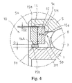
- Fig. 4 illustrates a second embodiment of the present invention.
- the dimension of the pole plate 14 in the radial direction is set so that a certain clearance (gap G2) is provided between the pole plate 14 and the inner peripheral surface of the outer ring 5.
- the magnet 12 may come into contact with the perpendicular surface 5c of the step due to a magnetic attraction force, and thereby be positioned and secured.
- the magnetic fluid is injected into the gap G and the gap G2 with an injection device, such as a syringe, the magnetic fluid is retained in the gap G (between the inner ring 3 and the pole plate 14) by the magnetic circuit 3M and in the gap G2 (between the outer ring 5 and the pole plate 14) by the magnetic circuit 5M.
- the magnetic fluid that fills the gap G may flow toward the step and be retained also in a step portion between the magnet 12 and the outer ring 5 (region between the magnet 12 and the outer ring 5). Therefore, the sealing effect at the outer-ring side may be increased.
- the pole plate 14 having the magnet 12 bonded thereto can be easily assembled.
- the orientations of the magnets can be easily controlled.
- the pole plate 14 is formed so that the gap G2 is provided, the outer ring 3 does not receive a deformation load during the assembly, and the rotational performance of the bearing is not degraded.
- the gap G2 may be set in the range of 10 to 500 ⁇ m, preferably in the range of 20 to 200 ⁇ m.
- Fig. 5 is a diagram illustrating a modification of the second embodiment.
- a step 3b may be formed on an inner ring, and a perpendicular surface 3c that is perpendicular to an axial direction may be formed on the step 3b.
- a magnet 12 and a pole plate 14 similar to those in the structure illustrated in Fig. 4 may be disposed on the inner ring (the structure may be symmetrical to that illustrated in Fig. 4 ).
- the bearing having this structure may be suitable for a case in which the outer ring is attached to a rotating member.
- the magnet 12 and the pole plate 14 may be attached to the inner ring as in the structure illustrated in Fig. 5 .
- Fig. 6 is a diagram illustrating a third embodiment of the present invention.
- an outer ring 5 may be formed so as to be longer than an inner ring 3 in an axial direction, and may include an elongate cylindrical portion 5D that projects from an exposed end surface 3a of the inner ring 3.
- a magnetic fluid seal 10 having a structure similar to the above-described structure may be provided on the elongate cylindrical portion 5D.
- the length of the elongate cylindrical portion 5D in the axial direction may be set so that a gap G3 is provided between a magnet 12 and the exposed end surface 3a of the inner ring 3 in the state in which the magnet 12 is attached to a perpendicular surface 5c of a step 5b on the outer ring by attraction and is thereby positioned and secured.
- the dimension H of the magnet 12 in the radial direction may be larger than those in the above-described embodiments and modifications. Therefore, the magnetic force can be increased and the sealing effect (ability to retain the magnetic fluid) can be enhanced.
- inner-ring-side magnetic fluid 15b may be disposed in an inner region in the axial direction so as not to be exposed to the outside, the inner-ring-side magnetic fluid 15b may be prevented from being wiped off during the assembly, and an injection process can be reliably performed.
- the outer ring 5 has the elongate cylindrical portion in this embodiment, the inner ring 3 may instead have an elongate cylindrical portion.
- the surfaces of the inner ring 3 and the outer ring 5 are preferably treated with electrolytic chromic acid.
- electrolytic chromic acid When the treatment with electrolytic chromic acid is performed, the occurrence of cracks and tears in the surfaces due to rust or corrosion can be prevented, and intrusion of dust and foreign matter into an inner region can be reliably prevented.
- a ring-shaped shield may be press-fitted to the outer surface of the pole plate 14, which is disposed at the opening side, in the axial direction from an outer position in the axial direction.
- the shield may be formed of a material having a high corrosion resistance and a high heat resistance, such as a stainless steel (SUS304) or a resin.
- SUS304 stainless steel
- a resin such as a resin.
- a thin washer or a positioning spacer member may be disposed between the magnet 12 and the outer ring 5 (or the inner ring 3).
- dimensional control can be simplified and ease of assembly can be further improved.
- the washer or the spacer is preferably formed of a magnetic member so that stable magnetic circuits can be formed.
- the bearings with the magnetic fluid seals having the above-described structures may be attached to rotating shaft portions of various devices that are required to be dustproof and waterproof.
- severe conditions are expected in an environment where salt (seawater) exists. More specifically, seawater easily intrudes through small gaps since it has a low velocity, and when the seawater that has intruded dries, it leaves salt crystals. If these crystals adhere to the rolling elements, the rotational performance will be greatly degraded.
- Table 1 shows the result of a test in which the bearings according to the above-described embodiments and bearings having the structures according to the related art were attached to rotating shaft portions that are rotated by handles of spinning reels, and in which the rotational performances of the bearings (degrees of smoothness the operator feels when rotating the handles) were evaluated after immersing them in salt water.
- Example 1 is an example in which a bearing on a handle shaft (rotating shaft) is sealed with a commonly known rubber packing material.
- Related Art Example 2 is an example in which a bearing is provided with a magnetic fluid seal but a magnet is clamped by two pole plates and fixed to an outer ring (type disclosed in Japanese Unexamined Utility Model Registration Application Publication No. 1-91125 ).
- Example 1 is an example in which the bearing according to the above-described embodiment illustrated in Figs. 1 and 2 is used.
- Example 2 is an example in which the bearing according to the above-described embodiment illustrated in Fig. 4 is used.
- Example 3 is an example in which the bearing according to the above-described embodiment illustrated in Fig. 6 is used.
- the bearings having the above-described sealing functions of the respective structures were also evaluated for productivity in terms of ease of assembly thereof and ease of handling thereof in the process of attaching them to the handle shaft portions.
- ⁇ indicates that the assembly was very easy
- ⁇ indicates that the assembly was rather cumbersome
- X indicates that the assembly was cumbersome.
- ⁇ indicates that the bearing was very easy to handle
- O indicates that the bearing was easy to handle
- ⁇ indicates that the bearing needed to be handled with care.
- the rubber-packing-type bearing (Related Art Example 1) felt heavy during the operation due to large rotational resistance.
- the other magnetic-fluid-seal-type bearings (Related Art Example 2 and Examples 1 to 3) had small rotational resistances and felt light during the operation. None of the bearings felt rough during the rotation in the initial stage before they were immersed in salt water. When the rotating operation was performed after the immersion into salt water, the bearing having the structure of Related Art Example 2 felt rough. This is because the salt water intruded into the rolling element section through unsealed regions and formed crystals when it dried.
- Example 1 Although the bearing of Related Art Example 1 did not feel rough, it is expected that it will start to feel rough earlier than the bearings of Examples 1 to 3 when the experiment is repeated for a long time and the rubber packing material becomes degraded. In the structures of Examples 1 to 3, the magnetic fluid does not leak out, so that the rotation feels smooth for a long period of time.
- Example 1 With regard to the ease of handling, the rubber-packing-type bearing (Related Art Example 1) has no problem. With regard to the magnetic-fluid-seal-type bearings, in Example 3, there was no risk that the magnetic fluid will be wiped off by mistake since the magnetic fluid was disposed in an inner region. In Example 2, the magnetic fluid is disposed in a region slightly further toward the inner region than the opening, and is therefore not easily wiped off. In Example 1 and Related Art Example 2, the magnetic fluid is disposed in an end region, and there is a risk that the magnetic fluid will be wiped off by mistake. Therefore, these bearings need to be handled with care.
- the structures of the present invention showed superior results in terms of sealing effect and productivity.
Landscapes
- Engineering & Computer Science (AREA)
- General Engineering & Computer Science (AREA)
- Mechanical Engineering (AREA)
- Sealing Using Fluids, Sealing Without Contact, And Removal Of Oil (AREA)
- Rolling Contact Bearings (AREA)
- Sealing Of Bearings (AREA)
Priority Applications (1)
| Application Number | Priority Date | Filing Date | Title |
|---|---|---|---|
| EP17157501.2A EP3190301B1 (de) | 2012-04-26 | 2013-04-16 | Lager mit magnetischer fluiddichtung |
Applications Claiming Priority (2)
| Application Number | Priority Date | Filing Date | Title |
|---|---|---|---|
| JP2012100551A JP5797600B2 (ja) | 2012-04-26 | 2012-04-26 | 磁性流体シール付き軸受 |
| EP13781951.2A EP2762739B1 (de) | 2012-04-26 | 2013-04-16 | Lager mit magnetfluiddichtung |
Related Parent Applications (2)
| Application Number | Title | Priority Date | Filing Date |
|---|---|---|---|
| EP13781951.2A Division EP2762739B1 (de) | 2012-04-26 | 2013-04-16 | Lager mit magnetfluiddichtung |
| EP13781951.2A Division-Into EP2762739B1 (de) | 2012-04-26 | 2013-04-16 | Lager mit magnetfluiddichtung |
Related Child Applications (2)
| Application Number | Title | Priority Date | Filing Date |
|---|---|---|---|
| EP17157501.2A Division EP3190301B1 (de) | 2012-04-26 | 2013-04-16 | Lager mit magnetischer fluiddichtung |
| EP17157501.2A Division-Into EP3190301B1 (de) | 2012-04-26 | 2013-04-16 | Lager mit magnetischer fluiddichtung |
Publications (2)
| Publication Number | Publication Date |
|---|---|
| EP2952764A1 true EP2952764A1 (de) | 2015-12-09 |
| EP2952764B1 EP2952764B1 (de) | 2018-02-14 |
Family
ID=49482948
Family Applications (4)
| Application Number | Title | Priority Date | Filing Date |
|---|---|---|---|
| EP13781951.2A Active EP2762739B1 (de) | 2012-04-26 | 2013-04-16 | Lager mit magnetfluiddichtung |
| EP15170606.6A Active EP3009699B1 (de) | 2012-04-26 | 2013-04-16 | Lager mit magnetischer fluiddichtung |
| EP17157501.2A Active EP3190301B1 (de) | 2012-04-26 | 2013-04-16 | Lager mit magnetischer fluiddichtung |
| EP15170607.4A Active EP2952764B1 (de) | 2012-04-26 | 2013-04-16 | Lager mit magnetischer fluiddichtung |
Family Applications Before (3)
| Application Number | Title | Priority Date | Filing Date |
|---|---|---|---|
| EP13781951.2A Active EP2762739B1 (de) | 2012-04-26 | 2013-04-16 | Lager mit magnetfluiddichtung |
| EP15170606.6A Active EP3009699B1 (de) | 2012-04-26 | 2013-04-16 | Lager mit magnetischer fluiddichtung |
| EP17157501.2A Active EP3190301B1 (de) | 2012-04-26 | 2013-04-16 | Lager mit magnetischer fluiddichtung |
Country Status (8)
| Country | Link |
|---|---|
| US (3) | US9091302B2 (de) |
| EP (4) | EP2762739B1 (de) |
| JP (1) | JP5797600B2 (de) |
| KR (1) | KR101955742B1 (de) |
| CN (2) | CN105673709B (de) |
| BR (2) | BR122021024766B1 (de) |
| RU (1) | RU2578628C1 (de) |
| WO (1) | WO2013161625A1 (de) |
Families Citing this family (20)
| Publication number | Priority date | Publication date | Assignee | Title |
|---|---|---|---|---|
| WO2013110334A1 (en) * | 2012-01-26 | 2013-08-01 | Aktiebolaget Skf | Rolling bearing assembly having magnetic and/or electronic elements |
| JP6342640B2 (ja) * | 2013-10-25 | 2018-06-13 | グローブライド株式会社 | 魚釣用リール |
| JP5913254B2 (ja) * | 2013-10-30 | 2016-04-27 | グローブライド株式会社 | 魚釣用リール |
| JP6231355B2 (ja) * | 2013-11-06 | 2017-11-15 | グローブライド株式会社 | 磁性流体シール付き軸受、及び磁性流体シール付き軸受を配設した魚釣用リール |
| JP6209096B2 (ja) * | 2014-02-06 | 2017-10-04 | グローブライド株式会社 | 魚釣用スピニングリール |
| JP6462339B2 (ja) * | 2014-11-28 | 2019-01-30 | グローブライド株式会社 | 磁性流体シール付き軸受および該軸受を備える魚釣用リール |
| CN105317848B (zh) | 2014-07-29 | 2017-12-12 | 古洛布莱株式会社 | 磁流体密封式轴承及具备该轴承的钓鱼用卷线器 |
| JP6231468B2 (ja) * | 2014-11-27 | 2017-11-15 | グローブライド株式会社 | 磁性流体シール付き軸受、及び磁性流体シール付き軸受を配設した魚釣用リール |
| JP6574118B2 (ja) * | 2015-08-28 | 2019-09-11 | グローブライド株式会社 | 磁性流体シール付き軸受 |
| US10143189B2 (en) | 2015-10-21 | 2018-12-04 | Pure Fishing Japan Co., Ltd | Fishing reel |
| JP2017096451A (ja) | 2015-11-26 | 2017-06-01 | グローブライド株式会社 | 磁性流体シール付き軸受 |
| JP6737660B2 (ja) * | 2016-08-30 | 2020-08-12 | グローブライド株式会社 | 磁性流体シール付き軸受ユニット、及び、そのような軸受ユニットを備えた駆動モータ |
| JP6683574B2 (ja) | 2016-08-31 | 2020-04-22 | グローブライド株式会社 | 無人飛行体 |
| FR3063326B1 (fr) * | 2017-02-27 | 2019-04-26 | Safran Aircraft Engines | Joint axial asservi comportant un dispositif magnetique de positionnement axial |
| KR101973943B1 (ko) | 2017-05-23 | 2019-05-02 | 한국과학기술연구원 | 볼 베어링 |
| JP7133263B2 (ja) | 2017-09-29 | 2022-09-08 | グローブライド株式会社 | 磁性流体シール装置及び磁性流体シール付き軸受 |
| CN112728107B (zh) * | 2020-12-31 | 2022-02-01 | 清华大学 | 磁性液体密封装置 |
| CN114251368B (zh) * | 2021-11-25 | 2023-10-27 | 广西科技大学 | 一种轴承用嵌入式磁流体密封装置 |
| CN117212342B (zh) * | 2023-09-28 | 2025-03-14 | 太原科技大学 | 一种高精度磁性纳米薄膜润滑装置 |
| PL132326U1 (pl) * | 2024-08-20 | 2025-05-12 | Politechnika Świętokrzyska | Łożysko toczne z uszczelnieniem magnetycznym |
Citations (6)
| Publication number | Priority date | Publication date | Assignee | Title |
|---|---|---|---|---|
| JPS5733222A (en) | 1980-08-08 | 1982-02-23 | Nippon Seiko Kk | Sealed antifriction bearing |
| JPH0191125U (de) | 1987-12-09 | 1989-06-15 | ||
| JPH0276224U (de) * | 1988-11-30 | 1990-06-12 | ||
| JPH02286967A (ja) * | 1989-04-28 | 1990-11-27 | Nippon Seiko Kk | 磁性流体シール装置 |
| US5152539A (en) * | 1987-07-17 | 1992-10-06 | Koyo Seiko Co., Ltd. | Ferrofluid seal apparatus |
| JP2000224799A (ja) * | 1999-01-29 | 2000-08-11 | Nippon Densan Corp | スピンドルモータ |
Family Cites Families (24)
| Publication number | Priority date | Publication date | Assignee | Title |
|---|---|---|---|---|
| US4628384A (en) * | 1983-08-26 | 1986-12-09 | Ferrofluidics Corporation | Bearing assembly with integrated ferrofluid seal |
| US4842426A (en) * | 1985-09-09 | 1989-06-27 | Nippon Seiko Kabushiki Kaisha | Bearing assembly |
| US4844138A (en) * | 1986-09-01 | 1989-07-04 | Kabushiki Kaisha Tokai Rika Denki Seisakusho | Automobile tire pneumatic pressure controlling apparatus |
| JPS6487921A (en) | 1987-09-29 | 1989-04-03 | Nippon Seiko Kk | Rolling bearing |
| JPH01149066A (ja) | 1987-12-07 | 1989-06-12 | Fuji Xerox Co Ltd | 記録装置 |
| JPH0713425Y2 (ja) * | 1988-07-11 | 1995-03-29 | 日本電産株式会社 | スピンドルモータ |
| JP2569754B2 (ja) | 1988-09-10 | 1997-01-08 | 富士通株式会社 | 化合物半導体装置の製造方法 |
| US5161902A (en) * | 1988-09-29 | 1992-11-10 | Nippon Seiko Kabushiki Kaisha | Magnetic sealing device for use between first and second magnetic members which rotate relative to each other |
| JPH02138519A (ja) * | 1988-09-29 | 1990-05-28 | Nippon Seiko Kk | 磁性流体シール装置付転がり軸受 |
| US5051853A (en) * | 1989-04-26 | 1991-09-24 | Nippon Seiko Kabushiki Kaisha | Magnetic disc device |
| JPH0429680A (ja) * | 1990-05-26 | 1992-01-31 | Nippon Densan Corp | 軸受装置 |
| JPH0571648A (ja) * | 1991-02-18 | 1993-03-23 | Nippon Seiko Kk | 磁性流体シール装置の組み立て方法 |
| CN1066463A (zh) * | 1991-05-05 | 1992-11-25 | 张华明 | 磁性密封润滑脂及其密封装置 |
| JP2868029B2 (ja) * | 1991-06-27 | 1999-03-10 | 富士通株式会社 | 精密平面調芯機構 |
| JP2767778B2 (ja) | 1991-08-08 | 1998-06-18 | ウシオ電機株式会社 | フィルム露光装置 |
| JPH0565922A (ja) * | 1991-09-04 | 1993-03-19 | Nippon Ferrofluidics Kk | シール機能を備えた軸受装置 |
| JPH11276042A (ja) * | 1998-03-26 | 1999-10-12 | Shimano Inc | 釣り用リールのシール機構 |
| JP2003319742A (ja) | 2002-05-07 | 2003-11-11 | Shimano Inc | 両軸受リールの回転支持構造 |
| JP2004251293A (ja) * | 2003-02-18 | 2004-09-09 | Uchiyama Mfg Corp | トーンホイール付シールリング及びその製造方法 |
| JP4943406B2 (ja) * | 2008-11-06 | 2012-05-30 | グローブライド株式会社 | 魚釣用リール |
| JP4886066B2 (ja) * | 2010-01-19 | 2012-02-29 | グローブライド株式会社 | 魚釣用スピニングリール |
| EP3156674B1 (de) * | 2010-07-05 | 2021-02-24 | Eagle Industry Co., Ltd. | Wälzlager umfassend eine dichtungsanordnung mit magnetischen schmiermittel |
| RU100165U1 (ru) * | 2010-07-23 | 2010-12-10 | Государственное образовательное учреждение высшего профессионального образования "Ивановский государственный энергетический университет имени В.И. Ленина" (ИГЭУ) | Подшипник качения с магнитожидкостным уплотнением |
| KR101930538B1 (ko) * | 2010-08-27 | 2018-12-18 | 글로브라이드 가부시키가이샤 | 낚시용 릴 |
-
2012
- 2012-04-26 JP JP2012100551A patent/JP5797600B2/ja active Active
-
2013
- 2013-04-16 EP EP13781951.2A patent/EP2762739B1/de active Active
- 2013-04-16 KR KR1020147005728A patent/KR101955742B1/ko active Active
- 2013-04-16 EP EP15170606.6A patent/EP3009699B1/de active Active
- 2013-04-16 CN CN201610108379.7A patent/CN105673709B/zh active Active
- 2013-04-16 BR BR122021024766-8A patent/BR122021024766B1/pt active IP Right Grant
- 2013-04-16 EP EP17157501.2A patent/EP3190301B1/de active Active
- 2013-04-16 RU RU2014108457/11A patent/RU2578628C1/ru active
- 2013-04-16 WO PCT/JP2013/061269 patent/WO2013161625A1/ja not_active Ceased
- 2013-04-16 CN CN201380003249.1A patent/CN103842675B/zh active Active
- 2013-04-16 US US14/342,747 patent/US9091302B2/en active Active
- 2013-04-16 BR BR112014005584-0A patent/BR112014005584B1/pt active IP Right Grant
- 2013-04-16 EP EP15170607.4A patent/EP2952764B1/de active Active
-
2015
- 2015-05-29 US US14/726,198 patent/US9546685B2/en active Active
-
2016
- 2016-10-24 US US15/332,655 patent/US9611893B2/en active Active
Patent Citations (6)
| Publication number | Priority date | Publication date | Assignee | Title |
|---|---|---|---|---|
| JPS5733222A (en) | 1980-08-08 | 1982-02-23 | Nippon Seiko Kk | Sealed antifriction bearing |
| US5152539A (en) * | 1987-07-17 | 1992-10-06 | Koyo Seiko Co., Ltd. | Ferrofluid seal apparatus |
| JPH0191125U (de) | 1987-12-09 | 1989-06-15 | ||
| JPH0276224U (de) * | 1988-11-30 | 1990-06-12 | ||
| JPH02286967A (ja) * | 1989-04-28 | 1990-11-27 | Nippon Seiko Kk | 磁性流体シール装置 |
| JP2000224799A (ja) * | 1999-01-29 | 2000-08-11 | Nippon Densan Corp | スピンドルモータ |
Non-Patent Citations (1)
| Title |
|---|
| OCHONSKI W: "ANWENDUNGSMOEGLICHKEITEN FUER MAGNETFLUESSIGKEITEN IN DER DICHTUNGSTECHNIK - TEIL I", ANTRIEBSTECHNIK, VEREINIGTE FACHVERLAGE, MAINZ, DE, vol. 35, no. 1, 1 January 1996 (1996-01-01), pages 47 - 49, XP000548142, ISSN: 0722-8546 * |
Also Published As
| Publication number | Publication date |
|---|---|
| JP5797600B2 (ja) | 2015-10-21 |
| CN105673709A (zh) | 2016-06-15 |
| US9091302B2 (en) | 2015-07-28 |
| US9546685B2 (en) | 2017-01-17 |
| KR101955742B1 (ko) | 2019-03-07 |
| EP2762739B1 (de) | 2016-04-13 |
| EP3009699B1 (de) | 2017-04-26 |
| EP2762739A1 (de) | 2014-08-06 |
| JP2013228044A (ja) | 2013-11-07 |
| US9611893B2 (en) | 2017-04-04 |
| CN103842675B (zh) | 2016-04-13 |
| EP2762739A4 (de) | 2015-05-06 |
| EP3190301B1 (de) | 2018-12-26 |
| BR112014005584A2 (pt) | 2017-06-13 |
| BR122021024766B1 (pt) | 2023-03-14 |
| CN105673709B (zh) | 2018-09-28 |
| EP3009699A1 (de) | 2016-04-20 |
| US20150063733A1 (en) | 2015-03-05 |
| US20170037905A1 (en) | 2017-02-09 |
| CN103842675A (zh) | 2014-06-04 |
| RU2578628C1 (ru) | 2016-03-27 |
| EP2952764B1 (de) | 2018-02-14 |
| BR112014005584B1 (pt) | 2022-06-28 |
| EP3190301A1 (de) | 2017-07-12 |
| US20160061263A1 (en) | 2016-03-03 |
| WO2013161625A1 (ja) | 2013-10-31 |
| KR20150005899A (ko) | 2015-01-15 |
Similar Documents
| Publication | Publication Date | Title |
|---|---|---|
| EP2762739B1 (de) | Lager mit magnetfluiddichtung | |
| KR102338754B1 (ko) | 자성 유체 시일이 부착된 베어링 및 자성 유체 시일이 부착된 베어링을 배치한 낚시용 릴 | |
| KR102338654B1 (ko) | 자성 유체 시일이 구비된 베어링 및 그 베어링을 구비하는 낚시용 릴 | |
| CN107795583B (zh) | 带有磁性流体密封的轴承单元及驱动马达 | |
| US9835202B2 (en) | Magnetic fluid sealed bearing | |
| JP6074329B2 (ja) | 磁性流体シール付き軸受 | |
| JP6074328B2 (ja) | 磁性流体シール付き軸受 | |
| EP3382224B1 (de) | Lager mit ferrofluiddichtung | |
| JP2016101104A (ja) | 磁性流体シール付き軸受、及び磁性流体シール付き軸受を配設した魚釣用リール | |
| JP6074468B2 (ja) | 磁性流体シール付き軸受 | |
| JP2016183782A (ja) | 磁性流体シール付き軸受 |
Legal Events
| Date | Code | Title | Description |
|---|---|---|---|
| PUAI | Public reference made under article 153(3) epc to a published international application that has entered the european phase |
Free format text: ORIGINAL CODE: 0009012 |
|
| 17P | Request for examination filed |
Effective date: 20150603 |
|
| AC | Divisional application: reference to earlier application |
Ref document number: 2762739 Country of ref document: EP Kind code of ref document: P |
|
| AK | Designated contracting states |
Kind code of ref document: A1 Designated state(s): AL AT BE BG CH CY CZ DE DK EE ES FI FR GB GR HR HU IE IS IT LI LT LU LV MC MK MT NL NO PL PT RO RS SE SI SK SM TR |
|
| RIC1 | Information provided on ipc code assigned before grant |
Ipc: F16C 33/76 20060101AFI20161108BHEP Ipc: F16C 19/06 20060101ALN20161108BHEP Ipc: F16J 15/43 20060101ALI20161108BHEP |
|
| GRAP | Despatch of communication of intention to grant a patent |
Free format text: ORIGINAL CODE: EPIDOSNIGR1 |
|
| RIC1 | Information provided on ipc code assigned before grant |
Ipc: F16J 15/43 20060101ALI20161212BHEP Ipc: F16C 19/06 20060101ALN20161212BHEP Ipc: F16C 33/76 20060101AFI20161212BHEP |
|
| INTG | Intention to grant announced |
Effective date: 20170109 |
|
| GRAS | Grant fee paid |
Free format text: ORIGINAL CODE: EPIDOSNIGR3 |
|
| GRAJ | Information related to disapproval of communication of intention to grant by the applicant or resumption of examination proceedings by the epo deleted |
Free format text: ORIGINAL CODE: EPIDOSDIGR1 |
|
| GRAL | Information related to payment of fee for publishing/printing deleted |
Free format text: ORIGINAL CODE: EPIDOSDIGR3 |
|
| INTC | Intention to grant announced (deleted) | ||
| RIC1 | Information provided on ipc code assigned before grant |
Ipc: F16C 33/76 20060101AFI20170330BHEP Ipc: F16J 15/43 20060101ALI20170330BHEP Ipc: F16C 19/06 20060101ALN20170330BHEP |
|
| 17Q | First examination report despatched |
Effective date: 20170601 |
|
| RIC1 | Information provided on ipc code assigned before grant |
Ipc: F16C 33/76 20060101AFI20171002BHEP Ipc: F16C 19/06 20060101ALN20171002BHEP Ipc: F16J 15/43 20060101ALI20171002BHEP |
|
| GRAJ | Information related to disapproval of communication of intention to grant by the applicant or resumption of examination proceedings by the epo deleted |
Free format text: ORIGINAL CODE: EPIDOSDIGR1 |
|
| GRAL | Information related to payment of fee for publishing/printing deleted |
Free format text: ORIGINAL CODE: EPIDOSDIGR3 |
|
| GRAP | Despatch of communication of intention to grant a patent |
Free format text: ORIGINAL CODE: EPIDOSNIGR1 |
|
| RIC1 | Information provided on ipc code assigned before grant |
Ipc: F16J 15/43 20060101ALI20171115BHEP Ipc: F16C 19/06 20060101ALN20171115BHEP Ipc: F16C 33/76 20060101AFI20171115BHEP |
|
| RIN1 | Information on inventor provided before grant (corrected) |
Inventor name: OHARA, TAKESHIGE |
|
| INTC | Intention to grant announced (deleted) | ||
| INTG | Intention to grant announced |
Effective date: 20171208 |
|
| GRAA | (expected) grant |
Free format text: ORIGINAL CODE: 0009210 |
|
| AC | Divisional application: reference to earlier application |
Ref document number: 2762739 Country of ref document: EP Kind code of ref document: P |
|
| AK | Designated contracting states |
Kind code of ref document: B1 Designated state(s): AL AT BE BG CH CY CZ DE DK EE ES FI FR GB GR HR HU IE IS IT LI LT LU LV MC MK MT NL NO PL PT RO RS SE SI SK SM TR |
|
| REG | Reference to a national code |
Ref country code: GB Ref legal event code: FG4D |
|
| REG | Reference to a national code |
Ref country code: CH Ref legal event code: EP |
|
| REG | Reference to a national code |
Ref country code: FR Ref legal event code: PLFP Year of fee payment: 6 |
|
| REG | Reference to a national code |
Ref country code: IE Ref legal event code: FG4D |
|
| REG | Reference to a national code |
Ref country code: DE Ref legal event code: R096 Ref document number: 602013033232 Country of ref document: DE Ref country code: AT Ref legal event code: REF Ref document number: 970031 Country of ref document: AT Kind code of ref document: T Effective date: 20180315 |
|
| REG | Reference to a national code |
Ref country code: NL Ref legal event code: MP Effective date: 20180214 |
|
| REG | Reference to a national code |
Ref country code: AT Ref legal event code: MK05 Ref document number: 970031 Country of ref document: AT Kind code of ref document: T Effective date: 20180214 |
|
| PG25 | Lapsed in a contracting state [announced via postgrant information from national office to epo] |
Ref country code: FI Free format text: LAPSE BECAUSE OF FAILURE TO SUBMIT A TRANSLATION OF THE DESCRIPTION OR TO PAY THE FEE WITHIN THE PRESCRIBED TIME-LIMIT Effective date: 20180214 Ref country code: CY Free format text: LAPSE BECAUSE OF FAILURE TO SUBMIT A TRANSLATION OF THE DESCRIPTION OR TO PAY THE FEE WITHIN THE PRESCRIBED TIME-LIMIT Effective date: 20180214 Ref country code: NL Free format text: LAPSE BECAUSE OF FAILURE TO SUBMIT A TRANSLATION OF THE DESCRIPTION OR TO PAY THE FEE WITHIN THE PRESCRIBED TIME-LIMIT Effective date: 20180214 Ref country code: LT Free format text: LAPSE BECAUSE OF FAILURE TO SUBMIT A TRANSLATION OF THE DESCRIPTION OR TO PAY THE FEE WITHIN THE PRESCRIBED TIME-LIMIT Effective date: 20180214 Ref country code: NO Free format text: LAPSE BECAUSE OF FAILURE TO SUBMIT A TRANSLATION OF THE DESCRIPTION OR TO PAY THE FEE WITHIN THE PRESCRIBED TIME-LIMIT Effective date: 20180514 Ref country code: ES Free format text: LAPSE BECAUSE OF FAILURE TO SUBMIT A TRANSLATION OF THE DESCRIPTION OR TO PAY THE FEE WITHIN THE PRESCRIBED TIME-LIMIT Effective date: 20180214 Ref country code: HR Free format text: LAPSE BECAUSE OF FAILURE TO SUBMIT A TRANSLATION OF THE DESCRIPTION OR TO PAY THE FEE WITHIN THE PRESCRIBED TIME-LIMIT Effective date: 20180214 |
|
| PG25 | Lapsed in a contracting state [announced via postgrant information from national office to epo] |
Ref country code: BG Free format text: LAPSE BECAUSE OF FAILURE TO SUBMIT A TRANSLATION OF THE DESCRIPTION OR TO PAY THE FEE WITHIN THE PRESCRIBED TIME-LIMIT Effective date: 20180514 Ref country code: AT Free format text: LAPSE BECAUSE OF FAILURE TO SUBMIT A TRANSLATION OF THE DESCRIPTION OR TO PAY THE FEE WITHIN THE PRESCRIBED TIME-LIMIT Effective date: 20180214 Ref country code: LV Free format text: LAPSE BECAUSE OF FAILURE TO SUBMIT A TRANSLATION OF THE DESCRIPTION OR TO PAY THE FEE WITHIN THE PRESCRIBED TIME-LIMIT Effective date: 20180214 Ref country code: SE Free format text: LAPSE BECAUSE OF FAILURE TO SUBMIT A TRANSLATION OF THE DESCRIPTION OR TO PAY THE FEE WITHIN THE PRESCRIBED TIME-LIMIT Effective date: 20180214 Ref country code: RS Free format text: LAPSE BECAUSE OF FAILURE TO SUBMIT A TRANSLATION OF THE DESCRIPTION OR TO PAY THE FEE WITHIN THE PRESCRIBED TIME-LIMIT Effective date: 20180214 Ref country code: GR Free format text: LAPSE BECAUSE OF FAILURE TO SUBMIT A TRANSLATION OF THE DESCRIPTION OR TO PAY THE FEE WITHIN THE PRESCRIBED TIME-LIMIT Effective date: 20180515 |
|
| PG25 | Lapsed in a contracting state [announced via postgrant information from national office to epo] |
Ref country code: PL Free format text: LAPSE BECAUSE OF FAILURE TO SUBMIT A TRANSLATION OF THE DESCRIPTION OR TO PAY THE FEE WITHIN THE PRESCRIBED TIME-LIMIT Effective date: 20180214 Ref country code: EE Free format text: LAPSE BECAUSE OF FAILURE TO SUBMIT A TRANSLATION OF THE DESCRIPTION OR TO PAY THE FEE WITHIN THE PRESCRIBED TIME-LIMIT Effective date: 20180214 Ref country code: RO Free format text: LAPSE BECAUSE OF FAILURE TO SUBMIT A TRANSLATION OF THE DESCRIPTION OR TO PAY THE FEE WITHIN THE PRESCRIBED TIME-LIMIT Effective date: 20180214 Ref country code: AL Free format text: LAPSE BECAUSE OF FAILURE TO SUBMIT A TRANSLATION OF THE DESCRIPTION OR TO PAY THE FEE WITHIN THE PRESCRIBED TIME-LIMIT Effective date: 20180214 |
|
| REG | Reference to a national code |
Ref country code: DE Ref legal event code: R097 Ref document number: 602013033232 Country of ref document: DE |
|
| PG25 | Lapsed in a contracting state [announced via postgrant information from national office to epo] |
Ref country code: MC Free format text: LAPSE BECAUSE OF FAILURE TO SUBMIT A TRANSLATION OF THE DESCRIPTION OR TO PAY THE FEE WITHIN THE PRESCRIBED TIME-LIMIT Effective date: 20180214 Ref country code: DK Free format text: LAPSE BECAUSE OF FAILURE TO SUBMIT A TRANSLATION OF THE DESCRIPTION OR TO PAY THE FEE WITHIN THE PRESCRIBED TIME-LIMIT Effective date: 20180214 Ref country code: SM Free format text: LAPSE BECAUSE OF FAILURE TO SUBMIT A TRANSLATION OF THE DESCRIPTION OR TO PAY THE FEE WITHIN THE PRESCRIBED TIME-LIMIT Effective date: 20180214 Ref country code: SK Free format text: LAPSE BECAUSE OF FAILURE TO SUBMIT A TRANSLATION OF THE DESCRIPTION OR TO PAY THE FEE WITHIN THE PRESCRIBED TIME-LIMIT Effective date: 20180214 Ref country code: CZ Free format text: LAPSE BECAUSE OF FAILURE TO SUBMIT A TRANSLATION OF THE DESCRIPTION OR TO PAY THE FEE WITHIN THE PRESCRIBED TIME-LIMIT Effective date: 20180214 |
|
| REG | Reference to a national code |
Ref country code: CH Ref legal event code: PL |
|
| REG | Reference to a national code |
Ref country code: BE Ref legal event code: MM Effective date: 20180430 |
|
| PLBE | No opposition filed within time limit |
Free format text: ORIGINAL CODE: 0009261 |
|
| STAA | Information on the status of an ep patent application or granted ep patent |
Free format text: STATUS: NO OPPOSITION FILED WITHIN TIME LIMIT |
|
| 26N | No opposition filed |
Effective date: 20181115 |
|
| REG | Reference to a national code |
Ref country code: IE Ref legal event code: MM4A |
|
| PG25 | Lapsed in a contracting state [announced via postgrant information from national office to epo] |
Ref country code: LU Free format text: LAPSE BECAUSE OF NON-PAYMENT OF DUE FEES Effective date: 20180416 |
|
| PG25 | Lapsed in a contracting state [announced via postgrant information from national office to epo] |
Ref country code: BE Free format text: LAPSE BECAUSE OF NON-PAYMENT OF DUE FEES Effective date: 20180430 Ref country code: CH Free format text: LAPSE BECAUSE OF NON-PAYMENT OF DUE FEES Effective date: 20180430 Ref country code: LI Free format text: LAPSE BECAUSE OF NON-PAYMENT OF DUE FEES Effective date: 20180430 Ref country code: SI Free format text: LAPSE BECAUSE OF FAILURE TO SUBMIT A TRANSLATION OF THE DESCRIPTION OR TO PAY THE FEE WITHIN THE PRESCRIBED TIME-LIMIT Effective date: 20180214 |
|
| PG25 | Lapsed in a contracting state [announced via postgrant information from national office to epo] |
Ref country code: IE Free format text: LAPSE BECAUSE OF NON-PAYMENT OF DUE FEES Effective date: 20180416 |
|
| PG25 | Lapsed in a contracting state [announced via postgrant information from national office to epo] |
Ref country code: MT Free format text: LAPSE BECAUSE OF NON-PAYMENT OF DUE FEES Effective date: 20180416 |
|
| PG25 | Lapsed in a contracting state [announced via postgrant information from national office to epo] |
Ref country code: TR Free format text: LAPSE BECAUSE OF FAILURE TO SUBMIT A TRANSLATION OF THE DESCRIPTION OR TO PAY THE FEE WITHIN THE PRESCRIBED TIME-LIMIT Effective date: 20180214 |
|
| PG25 | Lapsed in a contracting state [announced via postgrant information from national office to epo] |
Ref country code: PT Free format text: LAPSE BECAUSE OF FAILURE TO SUBMIT A TRANSLATION OF THE DESCRIPTION OR TO PAY THE FEE WITHIN THE PRESCRIBED TIME-LIMIT Effective date: 20180214 |
|
| PG25 | Lapsed in a contracting state [announced via postgrant information from national office to epo] |
Ref country code: MK Free format text: LAPSE BECAUSE OF NON-PAYMENT OF DUE FEES Effective date: 20180214 Ref country code: HU Free format text: LAPSE BECAUSE OF FAILURE TO SUBMIT A TRANSLATION OF THE DESCRIPTION OR TO PAY THE FEE WITHIN THE PRESCRIBED TIME-LIMIT; INVALID AB INITIO Effective date: 20130416 |
|
| PG25 | Lapsed in a contracting state [announced via postgrant information from national office to epo] |
Ref country code: IS Free format text: LAPSE BECAUSE OF FAILURE TO SUBMIT A TRANSLATION OF THE DESCRIPTION OR TO PAY THE FEE WITHIN THE PRESCRIBED TIME-LIMIT Effective date: 20180614 |
|
| P01 | Opt-out of the competence of the unified patent court (upc) registered |
Effective date: 20230515 |
|
| PGFP | Annual fee paid to national office [announced via postgrant information from national office to epo] |
Ref country code: DE Payment date: 20250305 Year of fee payment: 13 |
|
| PGFP | Annual fee paid to national office [announced via postgrant information from national office to epo] |
Ref country code: GB Payment date: 20260313 Year of fee payment: 14 |
|
| PGFP | Annual fee paid to national office [announced via postgrant information from national office to epo] |
Ref country code: IT Payment date: 20260320 Year of fee payment: 14 |
|
| PGFP | Annual fee paid to national office [announced via postgrant information from national office to epo] |
Ref country code: FR Payment date: 20260309 Year of fee payment: 14 |