EP2952780A2 - Transmission - Google Patents
Transmission Download PDFInfo
- Publication number
- EP2952780A2 EP2952780A2 EP15168793.6A EP15168793A EP2952780A2 EP 2952780 A2 EP2952780 A2 EP 2952780A2 EP 15168793 A EP15168793 A EP 15168793A EP 2952780 A2 EP2952780 A2 EP 2952780A2
- Authority
- EP
- European Patent Office
- Prior art keywords
- gear
- shaft
- hollow shaft
- transmission
- height
- Prior art date
- Legal status (The legal status is an assumption and is not a legal conclusion. Google has not performed a legal analysis and makes no representation as to the accuracy of the status listed.)
- Withdrawn
Links
Images




Classifications
-
- A—HUMAN NECESSITIES
- A61—MEDICAL OR VETERINARY SCIENCE; HYGIENE
- A61G—TRANSPORT, PERSONAL CONVEYANCES, OR ACCOMMODATION SPECIALLY ADAPTED FOR PATIENTS OR DISABLED PERSONS; OPERATING TABLES OR CHAIRS; CHAIRS FOR DENTISTRY; FUNERAL DEVICES
- A61G7/00—Beds specially adapted for nursing; Devices for lifting patients or disabled persons
- A61G7/002—Beds specially adapted for nursing; Devices for lifting patients or disabled persons having adjustable mattress frame
- A61G7/012—Beds specially adapted for nursing; Devices for lifting patients or disabled persons having adjustable mattress frame raising or lowering of the whole mattress frame
-
- A—HUMAN NECESSITIES
- A61—MEDICAL OR VETERINARY SCIENCE; HYGIENE
- A61G—TRANSPORT, PERSONAL CONVEYANCES, OR ACCOMMODATION SPECIALLY ADAPTED FOR PATIENTS OR DISABLED PERSONS; OPERATING TABLES OR CHAIRS; CHAIRS FOR DENTISTRY; FUNERAL DEVICES
- A61G13/00—Operating tables; Auxiliary appliances therefor
- A61G13/02—Adjustable operating tables; Controls therefor
- A61G13/06—Adjustable operating tables; Controls therefor raising or lowering of the whole table surface
-
- F—MECHANICAL ENGINEERING; LIGHTING; HEATING; WEAPONS; BLASTING
- F16—ENGINEERING ELEMENTS AND UNITS; GENERAL MEASURES FOR PRODUCING AND MAINTAINING EFFECTIVE FUNCTIONING OF MACHINES OR INSTALLATIONS; THERMAL INSULATION IN GENERAL
- F16H—GEARING
- F16H1/00—Toothed gearings for conveying rotary motion
- F16H1/02—Toothed gearings for conveying rotary motion without gears having orbital motion
- F16H1/20—Toothed gearings for conveying rotary motion without gears having orbital motion involving more than two intermeshing members
- F16H1/22—Toothed gearings for conveying rotary motion without gears having orbital motion involving more than two intermeshing members with a plurality of driving or driven shafts; with arrangements for dividing torque between two or more intermediate shafts
-
- F—MECHANICAL ENGINEERING; LIGHTING; HEATING; WEAPONS; BLASTING
- F16—ENGINEERING ELEMENTS AND UNITS; GENERAL MEASURES FOR PRODUCING AND MAINTAINING EFFECTIVE FUNCTIONING OF MACHINES OR INSTALLATIONS; THERMAL INSULATION IN GENERAL
- F16H—GEARING
- F16H25/00—Gearings comprising primarily only cams, cam-followers and screw-and-nut mechanisms
- F16H25/18—Gearings comprising primarily only cams, cam-followers and screw-and-nut mechanisms for conveying or interconverting oscillating or reciprocating motions
- F16H25/20—Screw mechanisms
-
- F—MECHANICAL ENGINEERING; LIGHTING; HEATING; WEAPONS; BLASTING
- F16—ENGINEERING ELEMENTS AND UNITS; GENERAL MEASURES FOR PRODUCING AND MAINTAINING EFFECTIVE FUNCTIONING OF MACHINES OR INSTALLATIONS; THERMAL INSULATION IN GENERAL
- F16H—GEARING
- F16H55/00—Elements with teeth or friction surfaces for conveying motion; Worms, pulleys or sheaves for gearing mechanisms
- F16H55/02—Toothed members; Worms
- F16H55/06—Use of materials; Use of treatments of toothed members or worms to affect their intrinsic material properties
-
- F—MECHANICAL ENGINEERING; LIGHTING; HEATING; WEAPONS; BLASTING
- F16—ENGINEERING ELEMENTS AND UNITS; GENERAL MEASURES FOR PRODUCING AND MAINTAINING EFFECTIVE FUNCTIONING OF MACHINES OR INSTALLATIONS; THERMAL INSULATION IN GENERAL
- F16H—GEARING
- F16H25/00—Gearings comprising primarily only cams, cam-followers and screw-and-nut mechanisms
- F16H25/18—Gearings comprising primarily only cams, cam-followers and screw-and-nut mechanisms for conveying or interconverting oscillating or reciprocating motions
- F16H25/20—Screw mechanisms
- F16H2025/2046—Screw mechanisms with gears arranged perpendicular to screw shaft axis, e.g. helical gears engaging tangentially the screw shaft
-
- F—MECHANICAL ENGINEERING; LIGHTING; HEATING; WEAPONS; BLASTING
- F16—ENGINEERING ELEMENTS AND UNITS; GENERAL MEASURES FOR PRODUCING AND MAINTAINING EFFECTIVE FUNCTIONING OF MACHINES OR INSTALLATIONS; THERMAL INSULATION IN GENERAL
- F16H—GEARING
- F16H25/00—Gearings comprising primarily only cams, cam-followers and screw-and-nut mechanisms
- F16H25/18—Gearings comprising primarily only cams, cam-followers and screw-and-nut mechanisms for conveying or interconverting oscillating or reciprocating motions
- F16H25/20—Screw mechanisms
- F16H2025/2053—Screws in parallel arrangement driven simultaneously with an output member moved by the screws
-
- F—MECHANICAL ENGINEERING; LIGHTING; HEATING; WEAPONS; BLASTING
- F16—ENGINEERING ELEMENTS AND UNITS; GENERAL MEASURES FOR PRODUCING AND MAINTAINING EFFECTIVE FUNCTIONING OF MACHINES OR INSTALLATIONS; THERMAL INSULATION IN GENERAL
- F16H—GEARING
- F16H25/00—Gearings comprising primarily only cams, cam-followers and screw-and-nut mechanisms
- F16H25/18—Gearings comprising primarily only cams, cam-followers and screw-and-nut mechanisms for conveying or interconverting oscillating or reciprocating motions
- F16H25/20—Screw mechanisms
- F16H2025/2059—Common movement by two screws or two nuts, e.g. two connected screws with opposite thread direction
-
- F—MECHANICAL ENGINEERING; LIGHTING; HEATING; WEAPONS; BLASTING
- F16—ENGINEERING ELEMENTS AND UNITS; GENERAL MEASURES FOR PRODUCING AND MAINTAINING EFFECTIVE FUNCTIONING OF MACHINES OR INSTALLATIONS; THERMAL INSULATION IN GENERAL
- F16H—GEARING
- F16H25/00—Gearings comprising primarily only cams, cam-followers and screw-and-nut mechanisms
- F16H25/18—Gearings comprising primarily only cams, cam-followers and screw-and-nut mechanisms for conveying or interconverting oscillating or reciprocating motions
- F16H25/20—Screw mechanisms
- F16H2025/2062—Arrangements for driving the actuator
- F16H2025/2084—Perpendicular arrangement of drive motor to screw axis
-
- F—MECHANICAL ENGINEERING; LIGHTING; HEATING; WEAPONS; BLASTING
- F16—ENGINEERING ELEMENTS AND UNITS; GENERAL MEASURES FOR PRODUCING AND MAINTAINING EFFECTIVE FUNCTIONING OF MACHINES OR INSTALLATIONS; THERMAL INSULATION IN GENERAL
- F16H—GEARING
- F16H25/00—Gearings comprising primarily only cams, cam-followers and screw-and-nut mechanisms
- F16H25/18—Gearings comprising primarily only cams, cam-followers and screw-and-nut mechanisms for conveying or interconverting oscillating or reciprocating motions
- F16H25/20—Screw mechanisms
- F16H2025/2062—Arrangements for driving the actuator
- F16H2025/209—Arrangements for driving the actuator using worm gears
-
- Y—GENERAL TAGGING OF NEW TECHNOLOGICAL DEVELOPMENTS; GENERAL TAGGING OF CROSS-SECTIONAL TECHNOLOGIES SPANNING OVER SEVERAL SECTIONS OF THE IPC; TECHNICAL SUBJECTS COVERED BY FORMER USPC CROSS-REFERENCE ART COLLECTIONS [XRACs] AND DIGESTS
- Y10—TECHNICAL SUBJECTS COVERED BY FORMER USPC
- Y10T—TECHNICAL SUBJECTS COVERED BY FORMER US CLASSIFICATION
- Y10T74/00—Machine element or mechanism
- Y10T74/18—Mechanical movements
- Y10T74/18568—Reciprocating or oscillating to or from alternating rotary
- Y10T74/18576—Reciprocating or oscillating to or from alternating rotary including screw and nut
- Y10T74/18616—Single input, plural outputs
Definitions
- Embodiments relate to a transmission for a height-adjustable shelf, for example a patient table, and a method for changing a height of a shelf, for example a patient table.
- Height-adjustable shelves are used in very different applications.
- the tray can be loaded and / or unloaded at a first height.
- a good or a person lying on the shelf may be handled, assessed and / or examined.
- Such trays can be used in medical applications, for example as couches, tables, patient table or the like. Due to the height adjustability of the tray, for example, a patient can be brought to a height in which the patient can be treated, transferred to another tray or couch and / or also be able to leave the tray again. In order to adjust the shelf in height, a variety of adjustment can be used.
- Embodiments relate to a transmission for a height adjustable shelf, such as a patient table, with at least one drive shaft and at least an output shaft. Further, the transmission comprises at least one gear, which is designed to transmit a rotational movement of the drive shaft to the output shaft.
- the gear comprises a plastic material.
- embodiments relate to a method for changing a height of a tray, such as a patient table.
- a drive shaft is driven and a rotational movement from the drive shaft to a gear, which has a plastic material, transmitted.
- the rotational movement is transmitted from the gear to an output shaft.
- the toothed wheel comprises a plastic
- vibration can be at least reduced or even completely avoided when carrying out the method or operating the transmission.
- a noise development can be at least reduced.
- a drive shaft may be, for example, a shaft which is driven by a drive, for example a drive motor and / or a manual drive.
- An output shaft may be, for example, a shaft that rotates about an axis that is parallel to the direction in which the height is changed.
- the gear can be made by milling.
- such a surface of the gear may be given a structure that is particularly low in noise and / or vibration in operation. Furthermore, in some embodiments, thereby also a simple production of the gear can be made possible.
- the drive shaft comprises a steel in some embodiments as a material.
- a particularly vibration-damping and / or low-noise material pairing can be provided by the combination of steel and plastic.
- the gear in some embodiments, a worm wheel.
- the drive shaft at least in the area in which it is engaged with the worm wheel, also have a worm toothing.
- a particularly low-vibration and low-noise toothing for torque transmission can thus be provided.
- the gear is interchangeable.
- the gearwheel because it optionally comprises a less wear-resistant material with plastic, can be changed in a simple manner during wear. Other components of the transmission may continue to be used.
- the transmission includes at least one second gear configured to drive a second output shaft.
- the second output shaft is formed, for example, to increase a stroke of the height adjustment per revolution. In some embodiments, such a height adjustment can be made with more or a larger stroke with the same installation dimension.
- the output shaft is in some embodiments, a hollow shaft, on whose jacket the gear is fixed.
- the gear can be replaced in a simple manner.
- the gear may be arranged concentrically with the hollow shaft.
- the two output shafts can be arranged parallel to one another and / or at a right angle to the drive shaft.
- the transmission includes a threaded rod with an external thread that is at least partially received in the hollow shaft.
- this also includes an adapter piece with an internal thread, which is designed to be in engagement with the external thread of the threaded rod and / or form raceways for balls.
- the adapter piece has an adapter fastening structure which is designed to connect the adapter piece with a corresponding hollow shaft fastening structure of the hollow shaft in a rotationally fixed manner.
- the threads can be engaged with each other, for example via balls or rollers.
- the internal thread and / or part of the raceway for the balls or Rollers are also introduced directly into the hollow shaft.
- the adapter piece omitted.
- Embodiments according to a further aspect also relate to a tray that is adjustable in height, for example, a patient table with a transmission according to at least one of the preceding embodiments.
- the shelf also includes a shelf whose position relative to a surface on which the shelf is changeable. In some embodiments, so the shelf or its shelf can be adjusted particularly low noise and / or low vibration at a height.
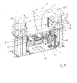
- Fig. 1a to 1j show different views and representations of a transmission 27 for a height adjustable shelf.
- the transmission 27 comprises a drive shaft 25, at least one output shaft 26 and at least one gear 28 which is adapted to transmit a rotational movement of the drive shaft 25 to the output shaft 26, wherein the gear 28 comprises a plastic material.
- the plastic may, for example, be a thermoplastic, for example polyoxymethylene (abbr. POM).
- the gear 28 may be made entirely of the plastic.
- only one surface or even functional surfaces of the gear 28 may comprise or be coated with the plastic.
- the gear parts are usually made of metallic materials.
- vibration and noise may occur. This is undesirable because it may, for example, limit comfort for a patient lying on the tray and / or an operator or surgeon.
- by changing the material of the at least one gear it may be possible to use a material containing the vibrations absorbed. As a result, vibrations and / or vibration noises that would otherwise occur in the transmission may be at least reduced.
- the at least one gear 28, which may also be referred to as a gear, is thus made of plastic or plastic materials to reduce noise and vibration.
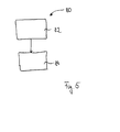
- Fig. 5 illustrated method 80 for changing a height of a tray are performed.
- a rotational movement is transmitted from the drive shaft 25 to the gear 28 having a plastic as a material. From this, the rotational movement is transmitted in a process 84 to the output shaft 26.
- the method 80 may be performed with other transmissions.
- the output shaft 26 is a hollow shaft 29 of a ball screw.
- the output shaft may also belong to a linear guide unit of another type, such as a sliding or a Wälzschraubtrieb.
- the transmission 27 includes a second gear 30, which analogous to the gear 28, a torque from the drive shaft 25 to a further output shaft which is formed as a hollow shaft 31 and belongs to a further ball screw transmits.
- the drive shaft 25 is, as in Fig. 1 recognizable, via a first roller bearing 85, which may be formed, for example, as a ball bearing, and a second roller bearing 86 rotatably mounted in a gear housing 87.
- the storage can also be done in other ways.
- the bearings can be designed as rolling bearings of different types, ball bearings, roller bearings, tapered roller bearings or the like.
- the drive shaft 25 has a worm gear 88.
- the worm gear 88 is located at one end of the drive shaft 25.
- the worm gear 88 of the drive shaft 25 comprises as a material a steel.
- the gears 28 and 30 have a corresponding worm toothing.
- the drive shaft and the gears may have other teeth which engage with each other.
- the gear housing 87 has in the direction of the drive shaft 25 an opening which is closed by a gear cover 100.
- a sealing ring 89 is inserted in the gear cover 100.
- the sealing ring 89 has, as in the enlargement of Fig. 1i recognizable, a sealing edge, which grinds on the drive shaft 25 and a surface of the drive shaft 25.
- a rolling bearing with a seal or other rolling bearing can be used with a seal.
- the seal may also be omitted.
- the gear 28 is supported in the axial direction against a stop 102 on an outer circumferential surface of the hollow shaft 29.
- the securing in the axial direction opposite takes place via a plurality of spacer rings 104, which rest in the axial direction via a bearing 110 or its inner ring 108 on a shoulder of the housing 87.
- the spacers 104 have a greater extent radially outward than the shoulder 106 and can thus fix the gear 28 in the axial direction.
- the spacers 104 are fixed in the axial direction via a rolling bearing 110 and the housing 87.
- the spacer rings 104 are supported against an inner ring 108 of the rolling bearing 110, via which the hollow shaft 29 is rotatably mounted relative to the housing 87.
- An outer ring 112 of the rolling bearing 110 is supported via an axial stop 114 of the housing 87.
- the hollow shaft 29 is also mounted via a second roller bearing 116 relative to the housing 87.
- An inner ring of the second roller bearing 116 is supported against an axial stop 118 on the hollow shaft.
- the two bearings 116 and 110 are arranged so that they receive the gear 28 in the axial direction between them. In the embodiment, three spacer rings between the gear 28 and the rolling bearing 110 are arranged. In some other, not shown embodiments, a different number of spacers and or other storage may be provided.
- the gear 28 is non-rotatably mounted on the hollow shaft 29 via a spring groove connection 120.
- the hollow shaft 29 and / or the gear 28 have a groove, for receiving a feather key.
- the rotationally fixed arrangement of the gear relative to the hollow shaft may be done in other ways.
- the hollow shaft 31 is mounted substantially analogous to the transmission housing 78 via roller bearings.
- the gear 30 is fixed analogously to the hollow shaft 31, as in the Fig. 1e recognizable.
- the hollow shafts 29 and 31, the gear housing 87 is closed in each case via a side part 122.
- the side part 122 has an opening through which a threaded rod 33, which is guided in the hollow shaft 29, protrudes.
- the hollow shaft 29 and the threaded rod 33 are components of a ball screw.
- the threaded rod 33 is movably guided with respect to the hollow shaft 29 via a plurality of balls, which run in raceways, which result between an Inngenwinde the hollow shaft 29 and an external thread of the threaded rod 33.
- the hollow shaft 29 includes threads, not shown, in which the balls can be returned again.
- the hollow shaft 31 is also a component of a ball screw. This comprises a threaded rod 35, which is also guided movably in the hollow shaft.
- the Fig. 2 . 3a and 3b show different views of an adjustment 1 for a height adjustable shelf, such as a patient table with the gear 27.
- the adjusting device 1 further comprises a drive motor 3, which is designed to change a height H of the adjusting device 1.
- the adjusting device 1 also comprises a manual drive 5, which is designed to change a height H of the adjusting device 1.
- a height H of the adjusting device 1 may be an extension of the adjusting device 1, perpendicular to a floor or a surface on which the adjusting device 1 is located.
- the manual drive 5 and also the drive motor 3 can drive the drive shaft 25, so that the drive shaft 25 rotates about an axis of rotation R.
- the drive motor may be, for example, an AC motor.
- the drive shaft 25 is perpendicular to the height H in which the adjusting device 1 can be adjusted, arranged. Via the drive shaft 25 and the transmission 27, which can also be referred to as a gear box, a height adjustment 7 can be driven or changed in height H.
- the rotational movement is thereby deflected by 90 °.
- the speed can be maintained.
- an over or a reduction can take place.
- the adjusting device 1 in addition to the first height adjustment device 7 also includes a second height adjustment device 9, which can be adjusted via a gear 27 ', which is substantially analogous to the transmission 27.
- a gear 27 ' which is substantially analogous to the transmission 27.
- Each of the height adjusting devices 7 and 9 is disposed at an opposite end of the drive shaft 25.
- the drive shaft 25 engages the gears 27 and 27 'in the manner described and adjusts the four ball screws.
- the height adjustment or the transmission may include other linear actuators or linear guides.
- the adjusting device 1 also comprises a first guide structure 11 and a second guide structure 13.
- the two guide structures 11 and 13 are arranged in the direction of the rotation axis R outside the two height adjustment devices 7 and 9. Both the two guide structures 11 and 13, as well as the two height adjustment devices 7 and 9 are each connected to a bottom plate 15 and a shelf 17.
- the hollow shaft 29 is fixed to the bottom plate 15 and the hollow shaft 31 on the tray 17.
- the storage plate 17 is marked in an extended state by the reference numeral 17 'and shown in phantom.
- the storage plate 17 serves, for example, for attaching or receiving a lying surface or receiving surface for a patient or an object that is to be recorded on the tray.
- the bottom plate 15 is disposed on a surface on which the adjusting device 1 stands.
- the storage plate 17 is arranged substantially parallel to the bottom plate 15.
- the bottom plate 15 and the tray 17 have similar dimensions. In some other embodiments, not shown, the bottom plate and the tray may also have different dimensions.
- the guide structures 11 and 13 serve to guide and stabilize an adjustment movement by the height adjustment devices 7 and 9 and have no drive themselves.
- the guide structures 11 and 13 are in each case similarly constructed, telescopically movable columns. In the following, therefore, only the guide structure 11 will be described in more detail.
- the guide structure 11 comprises three tubes 19, 21 and 23, each having a rectangular cross-section. In some other embodiments, not shown, the guide structure may also have a different number of tubes, for example five.
- the tube 19 with a largest cross section is connected to the bottom plate 15. In the tube 19 with the largest cross section, the tube 21 is arranged and guided with a central cross section in the direction of the height H.
- another tube 23 with a smallest cross-section is also movably arranged and guided in the direction of the height H.
- the tube 23 with the smallest cross-section is connected to the tray 17. Due to the cross-sectional shape, the tubes 19 to 23 can not rotate to each other.
- the two guide structures 11 and 13 can also be referred to as two telescopic columns, each with three cylindrical extensions, which comprise aluminum as a material.
- the adjusting device may also comprise no guide structures, only one guide structure or another type of guide structure, for example another linear guide unit.
- an adjustment for example, medical tables or patient tables to meet the needs for low noise and a low vibration occurring during an adjustment.
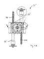
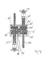
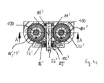
- the Fig. 4a to 4c show a further embodiment of a threaded rod 130 for the transmission.
- the threaded rod 130 comprises an adapter piece 131.
- the adapter piece 131 includes, as in the enlarged view of Fig. 4b Recognizable, a nut 133 which is engaged with an external thread of the threaded rod 130.
- the adapter piece 131 comprises a sleeve 135 which has threads 137 shown schematically. These form together with the threads of the threaded rod 130 running surfaces for a plurality of balls, not shown.
- the casing 139 has a greater extent in the axial direction than the sleeve 135 and comprises at an axial height of the nut 133 a depression 141, which nestles in a groove 143 of the sleeve 135.
- the groove 143 is circumferentially on an outer surface of the sleeve 135 at the level of the nut 133.
- the indentation 141 may be or include, for example, a thread that serves as an adapter mounting structure.
- the adapter piece 131 can be secured in a hollow shaft. This can also be the Hollow shaft have a corresponding thread as a hollow shaft mounting structure.
- the adapter piece 131 can also be threaded into the hollow shaft.
- the Fig. 4d and 4f show different representations of a transmission 27 "with the threaded rod 130 and the adapter piece 131.
- the gear 27" is substantially similar to the transmission 27 constructed. Identical or similar components are therefore identified by the same reference numerals under the addition of a "'". Instead of the gear 27 and 27 ', two gear 27 "can be used in the adjustment 1.
- a lower noise and a lower vibration when adjusting a shelf for medical applications can be made possible.
- the gear 27, a tray with the gear 27 or the method 80 can, as described for the figures in all sorts of medical applications, for example, for adjusting couches, beds, patient tables or the like can be used.
- the transmission 27 can be used for example in a lifting unit for a medical table.
- Such applications may be, for example, all sorts of applications or examinations, in particular X-ray applications or examinations, CT, CRT, MRI and / or MRI examinations. To increase comfort for a patient and / or for an operator, it is important that in such applications only low noise and minimal vibration occur.
- the gear 27 and method 80 may be used differently than described for the embodiments of the figures, in all sorts of other applications and applications, such as in manufacturing, for assembly purposes, or the like.
- features disclosed as a device feature in other embodiments may also be implemented as method features.
- features that in some embodiments implemented as method features be implemented as device features in other embodiments.
Landscapes
- Engineering & Computer Science (AREA)
- General Engineering & Computer Science (AREA)
- Health & Medical Sciences (AREA)
- Mechanical Engineering (AREA)
- Life Sciences & Earth Sciences (AREA)
- Animal Behavior & Ethology (AREA)
- General Health & Medical Sciences (AREA)
- Public Health (AREA)
- Veterinary Medicine (AREA)
- Biomedical Technology (AREA)
- Nursing (AREA)
- Physics & Mathematics (AREA)
- Electromagnetism (AREA)
- Thermal Sciences (AREA)
- Accommodation For Nursing Or Treatment Tables (AREA)
- Gear Transmission (AREA)
Applications Claiming Priority (1)
| Application Number | Priority Date | Filing Date | Title |
|---|---|---|---|
| DE102014210253.7A DE102014210253B4 (de) | 2014-05-28 | 2014-05-28 | Getriebe für eine in einer Höhe verstellbare Ablage sowie Verfahren zum Verändern einer Höhe einer Ablage |
Publications (2)
| Publication Number | Publication Date |
|---|---|
| EP2952780A2 true EP2952780A2 (fr) | 2015-12-09 |
| EP2952780A3 EP2952780A3 (fr) | 2016-07-27 |
Family
ID=53268675
Family Applications (1)
| Application Number | Title | Priority Date | Filing Date |
|---|---|---|---|
| EP15168793.6A Withdrawn EP2952780A3 (fr) | 2014-05-28 | 2015-05-22 | Transmission |
Country Status (4)
| Country | Link |
|---|---|
| US (1) | US10406051B2 (fr) |
| EP (1) | EP2952780A3 (fr) |
| CN (1) | CN105134898B (fr) |
| DE (1) | DE102014210253B4 (fr) |
Families Citing this family (6)
| Publication number | Priority date | Publication date | Assignee | Title |
|---|---|---|---|---|
| US10406044B2 (en) * | 2015-06-25 | 2019-09-10 | Stryker Corporation | Person support apparatuses with drive controls |
| DE102016224672A1 (de) * | 2016-12-12 | 2018-06-14 | Aktiebolaget Skf | Aktuator |
| DE102019205972A1 (de) * | 2019-04-25 | 2020-10-29 | Robert Bosch Gmbh | Elektromechanischer Bremsdruckerzeuger für ein hydraulisches Bremssystem eines Fahrzeugs sowie Fahrzeug umfassend einen elektromechanischen Bremsdruckerzeuger |
| DE102020201726A1 (de) | 2020-02-12 | 2021-08-12 | Robert Bosch Gesellschaft mit beschränkter Haftung | Zahnrad und Verfahren zur Herstellung eines Zahnrads |
| CA3202809A1 (fr) * | 2020-12-21 | 2022-06-30 | Cef Industries, Llc | Dispositif et procede de transmission de charge redondante a double entrainement |
| DE102023208272B4 (de) * | 2023-08-29 | 2025-10-02 | Siemens Healthineers Ag | Linearantriebsvorrichtung zur Umwandlung einer Rotationsbewegung in eine Linearbewegung und Medizintechnikvorrichtung, insbesondere ein Patientenlagerungstisch oder eine Bildgebungseinrichtung, aufweisend eine Linearantriebsvorrichtung |
Family Cites Families (35)
| Publication number | Priority date | Publication date | Assignee | Title |
|---|---|---|---|---|
| US1009186A (en) | 1911-04-12 | 1911-11-21 | Allan C Sargent | Jack. |
| US1018127A (en) | 1911-05-01 | 1912-02-20 | John Olson | Lifting-jack. |
| US1096316A (en) | 1912-08-26 | 1914-05-12 | Alanson C Noble | Bedstead end. |
| US1176751A (en) | 1914-04-27 | 1916-03-28 | Whiting Foundry Equipment Company | Locomotive screw-jack. |
| US1748948A (en) * | 1927-11-04 | 1930-03-04 | Schloemann Ag | Ingot-pushing device |
| US2522759A (en) | 1947-10-23 | 1950-09-19 | Lindquist Marie | Adjustable bed |
| US2870460A (en) | 1955-04-15 | 1959-01-27 | Russell T Sanford | Hospital bed |
| DE1182408B (de) | 1958-09-25 | 1964-11-26 | Trianco Ltd | Bewegliche Vorrichtung zum Beladen von Fahrzeugen und UEberladen von Guetern von einem Fahrzeug auf ein anderes |
| DE1168014B (de) | 1962-06-08 | 1964-04-16 | Berg Fa Wilh | Krankenbett |
| DE2626638A1 (de) | 1976-06-14 | 1977-12-22 | Stierlen Maquet Ag | Transporteinrichtung zum verlagern von liegenden patienten, insbesondere in krankenhaeusern |
| DE3003392A1 (de) | 1980-01-31 | 1981-08-06 | Bühnenbau Rolf Schnakenberg GmbH & Co KG, 5600 Wuppertal | Hoehenverstellbarer podestbock fuer theaterbuehnen o.dgl. |
| JP2587921B2 (ja) | 1986-05-29 | 1997-03-05 | 株式会社島津製作所 | 手術台 |
| US5269031A (en) | 1990-11-13 | 1993-12-14 | Alexander James H | Drive unit and clutch assembly for an adjustable bed |
| US5337627A (en) | 1991-12-27 | 1994-08-16 | Nissei Plastic Industrial Co., Ltd. | Ball screw |
| US6000076A (en) | 1996-10-23 | 1999-12-14 | Hill-Rom, Inc. | Procedural stretcher recline controls |
| US5803437A (en) * | 1997-03-26 | 1998-09-08 | Paterson; Richard | Chainless drive winch |
| CN2412709Y (zh) | 2000-02-15 | 2001-01-03 | 财团法人工业技术研究院 | 应用于标准机械介面双导螺杆倍行程与螺纹差动取放机构 |
| DE10129450A1 (de) * | 2001-06-19 | 2003-01-02 | Bosch Gmbh Robert | Stellglied für eine Fahrzeug-Lenkvorrichtung |
| DE20115608U1 (de) * | 2001-09-22 | 2003-02-13 | Flamme, Klaus Peter, Dipl.-Ing., 86916 Kaufering | Verstellantrieb mit zwei entgegengesetzt wirkenden Spindeln |
| DE102004016728A1 (de) | 2004-04-05 | 2005-10-13 | Siemens Ag | Hebevorrichtung |
| CN2770625Y (zh) | 2004-12-15 | 2006-04-12 | 于凤三 | 带手动摇把升降操纵机构的病床 |
| DE102005016183A1 (de) * | 2005-04-08 | 2006-10-12 | Robert Bosch Gmbh | Getriebezahnrad mit einer Anlaufscheibe, sowie Verfahren zum Herstellen eines solchen |
| US7712389B2 (en) * | 2006-05-16 | 2010-05-11 | T-Motion Technology Co., Ltd. | Lifting device having parallel double screw rods |
| DE202006008307U1 (de) * | 2006-05-24 | 2006-08-31 | T-MOTION Technology Co., Ltd., Xindian City | Hubvorrichtung mit Gewindestangen |
| US20110041632A1 (en) | 2006-10-18 | 2011-02-24 | Baker Michael C | Jam-tolerant dual-redundant differential-type actuators |
| CN201047429Y (zh) | 2007-05-08 | 2008-04-16 | 南通科技投资集团股份有限公司 | 双丝杆同步驱动机构 |
| US8672284B2 (en) | 2008-06-06 | 2014-03-18 | Linak A/S | Gear with at least two gearing stages, a linear actuator including such a gear and a table leg including such a linear actuator |
| CN201525138U (zh) | 2009-06-10 | 2010-07-14 | 东莞市华日金菱机械设备有限公司 | 两侧双光杠、丝杆传动装置 |
| JP4993225B2 (ja) | 2009-06-10 | 2012-08-08 | パラマウントベッド株式会社 | 操作ハンドルのトルク解放機構 |
| US8327971B2 (en) * | 2009-09-24 | 2012-12-11 | Mando Corporation | Reducer of electric power steering apparatus |
| US9154015B2 (en) * | 2010-03-24 | 2015-10-06 | Asmo Co., Ltd. | Speed reduction mechanism, motor with speed reduction mechanism, and method for producing speed reduction mechanism |
| US8424135B2 (en) | 2010-05-10 | 2013-04-23 | Drive Medical Design & Mfg | Universal bed system |
| CN103126841B (zh) | 2013-03-08 | 2015-01-14 | 海南大学 | 对接式手术病人转运车 |
| DE102013207142B4 (de) * | 2013-04-19 | 2014-12-11 | Ford Global Technologies, Llc | Schneckengetriebe |
| TWM466990U (zh) * | 2013-08-13 | 2013-12-01 | Timotion Technology Co Ltd | 具有多段式齒輪件的致動器 |
-
2014
- 2014-05-28 DE DE102014210253.7A patent/DE102014210253B4/de active Active
-
2015
- 2015-05-22 EP EP15168793.6A patent/EP2952780A3/fr not_active Withdrawn
- 2015-05-28 US US14/723,766 patent/US10406051B2/en active Active
- 2015-05-28 CN CN201510489051.XA patent/CN105134898B/zh active Active
Non-Patent Citations (1)
| Title |
|---|
| None |
Also Published As
| Publication number | Publication date |
|---|---|
| US20150342809A1 (en) | 2015-12-03 |
| CN105134898B (zh) | 2021-08-31 |
| US10406051B2 (en) | 2019-09-10 |
| EP2952780A3 (fr) | 2016-07-27 |
| DE102014210253A1 (de) | 2015-12-03 |
| DE102014210253B4 (de) | 2016-02-11 |
| CN105134898A (zh) | 2015-12-09 |
Similar Documents
| Publication | Publication Date | Title |
|---|---|---|
| DE102008033887B4 (de) | Teleskop-Doppelspindelantrieb | |
| DE102014210253B4 (de) | Getriebe für eine in einer Höhe verstellbare Ablage sowie Verfahren zum Verändern einer Höhe einer Ablage | |
| DE102015104484B4 (de) | Vierstufiger Teleskopaktor mit Gewindetrieb | |
| DE102012102802B4 (de) | Getriebe | |
| DE102014210250B4 (de) | Verstelleinrichtung für eine in einer Höhe verstellbare Ablage sowie Verfahren zum Verändern einer Höhe einer Ablage | |
| DE102019103384A1 (de) | Planetenwälzgewindetrieb | |
| DE102011007257A1 (de) | Antriebsvorrichtung mit wenigstens einer elektrischen Maschine | |
| DE102012015051A1 (de) | Planetengetriebe | |
| DE102016209161B4 (de) | Stelleinrichtung und Verwendung der Stelleinrichtung | |
| DE102018116867A1 (de) | Elektromechanischer Aktuator und Hinterachslenkung | |
| DE102022112862A1 (de) | Lenkungsanordnungen für ein Fahrzeug und Fahrzeug mit einer Lenksäule und einer Lenkungsanordnung | |
| EP3323717A1 (fr) | Mât rotor | |
| EP3581830A1 (fr) | Système d'engrenage | |
| DE102007039823B4 (de) | Antriebseinrichtung | |
| DE4325295A1 (de) | Spielfreies Planetengetriebe | |
| EP2255104B1 (fr) | Boite de vitesses | |
| DE69515181T2 (de) | Exzentergetriebe | |
| DE102010014393A1 (de) | Tragbares Motorwerkzeug mit einer Unwuchtausgleichsvorrichtung und einer Spannvorrichtung für ein rotationssymmetrisches Arbeitsmittel | |
| EP3819136B1 (fr) | Unité de roulement de roue pour un véhicule à moteur et procédé de fabrication d'une unité de roulement de roue | |
| DE102007005730A1 (de) | Differential mit Drehmomentverteilung für ein Kraftfahrzeug | |
| DE102011007264B4 (de) | Schalteinrichtung mit einer Schaltwalze | |
| DE10124267A1 (de) | Hydraulisches Pressgerät | |
| DE102005036362B4 (de) | Gehäuseloses Differential | |
| DE102016109150A1 (de) | Mechanisch geregelte Achsverstellung an Exzentergetrieben | |
| EP2441982B1 (fr) | Train épicycloïdal doté d'un premier ensemble de roues épicycloïdales et d'un deuxième ensemble de roues épicycloïdales, ainsi qu'une unité de construction dans un tel train épicycloïdal |
Legal Events
| Date | Code | Title | Description |
|---|---|---|---|
| PUAI | Public reference made under article 153(3) epc to a published international application that has entered the european phase |
Free format text: ORIGINAL CODE: 0009012 |
|
| AK | Designated contracting states |
Kind code of ref document: A2 Designated state(s): AL AT BE BG CH CY CZ DE DK EE ES FI FR GB GR HR HU IE IS IT LI LT LU LV MC MK MT NL NO PL PT RO RS SE SI SK SM TR |
|
| AX | Request for extension of the european patent |
Extension state: BA ME |
|
| PUAL | Search report despatched |
Free format text: ORIGINAL CODE: 0009013 |
|
| AK | Designated contracting states |
Kind code of ref document: A3 Designated state(s): AL AT BE BG CH CY CZ DE DK EE ES FI FR GB GR HR HU IE IS IT LI LT LU LV MC MK MT NL NO PL PT RO RS SE SI SK SM TR |
|
| AX | Request for extension of the european patent |
Extension state: BA ME |
|
| RIC1 | Information provided on ipc code assigned before grant |
Ipc: F16H 1/22 20060101AFI20160622BHEP |
|
| STAA | Information on the status of an ep patent application or granted ep patent |
Free format text: STATUS: THE APPLICATION IS DEEMED TO BE WITHDRAWN |
|
| 18D | Application deemed to be withdrawn |
Effective date: 20170128 |