EP2952781A1 - Kumulatives beschädigungsgradbeurteilungssystem und verfahren - Google Patents
Kumulatives beschädigungsgradbeurteilungssystem und verfahren Download PDFInfo
- Publication number
- EP2952781A1 EP2952781A1 EP15169755.4A EP15169755A EP2952781A1 EP 2952781 A1 EP2952781 A1 EP 2952781A1 EP 15169755 A EP15169755 A EP 15169755A EP 2952781 A1 EP2952781 A1 EP 2952781A1
- Authority
- EP
- European Patent Office
- Prior art keywords
- damage level
- evaluation
- cumulative damage
- cylinder block
- period
- Prior art date
- Legal status (The legal status is an assumption and is not a legal conclusion. Google has not performed a legal analysis and makes no representation as to the accuracy of the status listed.)
- Granted
Links
- 238000011156 evaluation Methods 0.000 title claims abstract description 259
- 230000001186 cumulative effect Effects 0.000 title claims abstract description 181
- 238000000034 method Methods 0.000 title claims description 19
- 230000002123 temporal effect Effects 0.000 claims description 31
- 238000012423 maintenance Methods 0.000 claims description 14
- 238000006073 displacement reaction Methods 0.000 claims description 12
- 238000005259 measurement Methods 0.000 claims description 9
- 238000010586 diagram Methods 0.000 description 13
- 125000004122 cyclic group Chemical group 0.000 description 2
- 230000002093 peripheral effect Effects 0.000 description 2
- 230000001360 synchronised effect Effects 0.000 description 2
- 230000002159 abnormal effect Effects 0.000 description 1
- 230000005540 biological transmission Effects 0.000 description 1
- 238000013461 design Methods 0.000 description 1
- 230000000694 effects Effects 0.000 description 1
Images






Classifications
-
- G—PHYSICS
- G05—CONTROLLING; REGULATING
- G05B—CONTROL OR REGULATING SYSTEMS IN GENERAL; FUNCTIONAL ELEMENTS OF SUCH SYSTEMS; MONITORING OR TESTING ARRANGEMENTS FOR SUCH SYSTEMS OR ELEMENTS
- G05B23/00—Testing or monitoring of control systems or parts thereof
- G05B23/02—Electric testing or monitoring
- G05B23/0205—Electric testing or monitoring by means of a monitoring system capable of detecting and responding to faults
- G05B23/0259—Electric testing or monitoring by means of a monitoring system capable of detecting and responding to faults characterized by the response to fault detection
- G05B23/0283—Predictive maintenance, e.g. involving the monitoring of a system and, based on the monitoring results, taking decisions on the maintenance schedule of the monitored system; Estimating remaining useful life [RUL]
-
- F—MECHANICAL ENGINEERING; LIGHTING; HEATING; WEAPONS; BLASTING
- F03—MACHINES OR ENGINES FOR LIQUIDS; WIND, SPRING, OR WEIGHT MOTORS; PRODUCING MECHANICAL POWER OR A REACTIVE PROPULSIVE THRUST, NOT OTHERWISE PROVIDED FOR
- F03D—WIND MOTORS
- F03D9/00—Adaptations of wind motors for special use; Combinations of wind motors with apparatus driven thereby; Wind motors specially adapted for installation in particular locations
- F03D9/20—Wind motors characterised by the driven apparatus
- F03D9/25—Wind motors characterised by the driven apparatus the apparatus being an electrical generator
-
- F—MECHANICAL ENGINEERING; LIGHTING; HEATING; WEAPONS; BLASTING
- F03—MACHINES OR ENGINES FOR LIQUIDS; WIND, SPRING, OR WEIGHT MOTORS; PRODUCING MECHANICAL POWER OR A REACTIVE PROPULSIVE THRUST, NOT OTHERWISE PROVIDED FOR
- F03D—WIND MOTORS
- F03D15/00—Transmission of mechanical power
-
- F—MECHANICAL ENGINEERING; LIGHTING; HEATING; WEAPONS; BLASTING
- F03—MACHINES OR ENGINES FOR LIQUIDS; WIND, SPRING, OR WEIGHT MOTORS; PRODUCING MECHANICAL POWER OR A REACTIVE PROPULSIVE THRUST, NOT OTHERWISE PROVIDED FOR
- F03D—WIND MOTORS
- F03D15/00—Transmission of mechanical power
- F03D15/20—Gearless transmission, i.e. direct-drive
-
- F—MECHANICAL ENGINEERING; LIGHTING; HEATING; WEAPONS; BLASTING
- F03—MACHINES OR ENGINES FOR LIQUIDS; WIND, SPRING, OR WEIGHT MOTORS; PRODUCING MECHANICAL POWER OR A REACTIVE PROPULSIVE THRUST, NOT OTHERWISE PROVIDED FOR
- F03D—WIND MOTORS
- F03D17/00—Monitoring or testing of wind motors, e.g. diagnostics
-
- F—MECHANICAL ENGINEERING; LIGHTING; HEATING; WEAPONS; BLASTING
- F03—MACHINES OR ENGINES FOR LIQUIDS; WIND, SPRING, OR WEIGHT MOTORS; PRODUCING MECHANICAL POWER OR A REACTIVE PROPULSIVE THRUST, NOT OTHERWISE PROVIDED FOR
- F03D—WIND MOTORS
- F03D9/00—Adaptations of wind motors for special use; Combinations of wind motors with apparatus driven thereby; Wind motors specially adapted for installation in particular locations
- F03D9/20—Wind motors characterised by the driven apparatus
- F03D9/28—Wind motors characterised by the driven apparatus the apparatus being a pump or a compressor
-
- F—MECHANICAL ENGINEERING; LIGHTING; HEATING; WEAPONS; BLASTING
- F16—ENGINEERING ELEMENTS AND UNITS; GENERAL MEASURES FOR PRODUCING AND MAINTAINING EFFECTIVE FUNCTIONING OF MACHINES OR INSTALLATIONS; THERMAL INSULATION IN GENERAL
- F16H—GEARING
- F16H57/00—General details of gearing
- F16H57/01—Monitoring wear or stress of gearing elements, e.g. for triggering maintenance
-
- F—MECHANICAL ENGINEERING; LIGHTING; HEATING; WEAPONS; BLASTING
- F05—INDEXING SCHEMES RELATING TO ENGINES OR PUMPS IN VARIOUS SUBCLASSES OF CLASSES F01-F04
- F05B—INDEXING SCHEME RELATING TO WIND, SPRING, WEIGHT, INERTIA OR LIKE MOTORS, TO MACHINES OR ENGINES FOR LIQUIDS COVERED BY SUBCLASSES F03B, F03D AND F03G
- F05B2260/00—Function
- F05B2260/40—Transmission of power
- F05B2260/406—Transmission of power through hydraulic systems
-
- F—MECHANICAL ENGINEERING; LIGHTING; HEATING; WEAPONS; BLASTING
- F16—ENGINEERING ELEMENTS AND UNITS; GENERAL MEASURES FOR PRODUCING AND MAINTAINING EFFECTIVE FUNCTIONING OF MACHINES OR INSTALLATIONS; THERMAL INSULATION IN GENERAL
- F16H—GEARING
- F16H61/00—Control functions within control units of change-speed- or reversing-gearings for conveying rotary motion ; Control of exclusively fluid gearing, friction gearing, gearings with endless flexible members or other particular types of gearing
- F16H61/38—Control of exclusively fluid gearing
- F16H61/40—Control of exclusively fluid gearing hydrostatic
-
- Y—GENERAL TAGGING OF NEW TECHNOLOGICAL DEVELOPMENTS; GENERAL TAGGING OF CROSS-SECTIONAL TECHNOLOGIES SPANNING OVER SEVERAL SECTIONS OF THE IPC; TECHNICAL SUBJECTS COVERED BY FORMER USPC CROSS-REFERENCE ART COLLECTIONS [XRACs] AND DIGESTS
- Y02—TECHNOLOGIES OR APPLICATIONS FOR MITIGATION OR ADAPTATION AGAINST CLIMATE CHANGE
- Y02E—REDUCTION OF GREENHOUSE GAS [GHG] EMISSIONS, RELATED TO ENERGY GENERATION, TRANSMISSION OR DISTRIBUTION
- Y02E10/00—Energy generation through renewable energy sources
- Y02E10/70—Wind energy
- Y02E10/72—Wind turbines with rotation axis in wind direction
-
- Y—GENERAL TAGGING OF NEW TECHNOLOGICAL DEVELOPMENTS; GENERAL TAGGING OF CROSS-SECTIONAL TECHNOLOGIES SPANNING OVER SEVERAL SECTIONS OF THE IPC; TECHNICAL SUBJECTS COVERED BY FORMER USPC CROSS-REFERENCE ART COLLECTIONS [XRACs] AND DIGESTS
- Y02—TECHNOLOGIES OR APPLICATIONS FOR MITIGATION OR ADAPTATION AGAINST CLIMATE CHANGE
- Y02E—REDUCTION OF GREENHOUSE GAS [GHG] EMISSIONS, RELATED TO ENERGY GENERATION, TRANSMISSION OR DISTRIBUTION
- Y02E60/00—Enabling technologies; Technologies with a potential or indirect contribution to GHG emissions mitigation
- Y02E60/16—Mechanical energy storage, e.g. flywheels or pressurised fluids
-
- Y—GENERAL TAGGING OF NEW TECHNOLOGICAL DEVELOPMENTS; GENERAL TAGGING OF CROSS-SECTIONAL TECHNOLOGIES SPANNING OVER SEVERAL SECTIONS OF THE IPC; TECHNICAL SUBJECTS COVERED BY FORMER USPC CROSS-REFERENCE ART COLLECTIONS [XRACs] AND DIGESTS
- Y02—TECHNOLOGIES OR APPLICATIONS FOR MITIGATION OR ADAPTATION AGAINST CLIMATE CHANGE
- Y02P—CLIMATE CHANGE MITIGATION TECHNOLOGIES IN THE PRODUCTION OR PROCESSING OF GOODS
- Y02P80/00—Climate change mitigation technologies for sector-wide applications
- Y02P80/10—Efficient use of energy, e.g. using compressed air or pressurized fluid as energy carrier
Definitions
- the present disclosure relates to a cumulative damage level evaluation system, a renewable energy power generating apparatus, a method of evaluating a cumulative damage level and a method of controlling a hydraulic machine.
- a hydraulic machine generally has features that allow it to exert great power with a relatively small structure, and that its output and velocity are easily controlled, for instance. Hydraulic machines are conventionally used for various purposes.
- Patent Document 1 discloses a wind turbine power generating apparatus configured to transmit rotational energy of a wind turbine rotor to a generator with a hydraulic transmission in which a variable-displacement hydraulic pump and a variable-displacement hydraulic motor, each of which serving as a hydraulic machine, are combined.
- the hydraulic pump includes a plurality of pistons and a cylinder block.
- the cylinder block includes a plurality of cylinders for forming a plurality of hydraulic chambers with the pistons and guiding reciprocating motion of the respective pistons, and a plurality of high pressure valves and a plurality of low pressure valves for switching the pressures of the respective hydraulic chambers.
- the output of the hydraulic pump is adjusted by varying the operation state of each hydraulic chamber.
- Patent Document 1 WO2014/002522A
- the cumulative fatigue damage rule is known as a method for evaluating a fatigue lifetime of a member of a machine.
- the cumulative fatigue damage rule is to calculate a cumulative damage level of a member of a machine taking account of a stress amplitude obtained from a stress waveform inputted into the member of the machine and occurrence frequency of the stress amplitude.
- an object of at least one embodiment of the present invention is to provide a cumulative damage level evaluation system for a hydraulic machine which can evaluate a total cumulative damage level over an entire evaluation period of each evaluation point of a cylinder block, appropriately taking account of an operation state of each hydraulic chamber in the entire evaluation period.
- a cumulative damage level evaluation system for a hydraulic machine is for a hydraulic machine which includes a plurality of pistons and at least one cylinder block.
- the at least one cylinder block includes a plurality of cylinders for forming a plurality of hydraulic chambers with the plurality of pistons and guiding reciprocating motion of the respective pistons.
- the at least one cylinder block also includes a plurality of high pressure valves and a plurality of low pressure valves for switching a pressure of each of the plurality of hydraulic chambers.
- the cumulative damage level evaluation system includes: an availability information acquisition part configured to obtain availability information which indicates an availability of each of the hydraulic chambers in an entire evaluation period; and a total cumulative damage level evaluation part configured to evaluate a total cumulative damage level over the entire evaluation period of each of evaluation points of the cylinder block based on the availability information obtained by the availability information acquisition part.
- the stress distribution in a cylinder block of a hydraulic machine varies in accordance with the operation state of each hydraulic chamber.
- the availability over the entire evaluation period of each hydraulic chamber affects the total cumulative damage level over the entire evaluation period at each position in the cylinder block.
- the cumulative damage level evaluation system for a hydraulic machine further includes a control part configured to control at least one of the plurality of high pressure valves or the plurality of low pressure valves in accordance with an operation pattern of the plurality of hydraulic chambers in the cylinder block.
- control part When the total cumulative damage level over the entire evaluation period of at least one of the evaluation points of the cylinder block is greater than a threshold value, the control part is configured to determine an operation pattern whereby it is possible to avoid stress concentration to the at least one evaluation point at which the cumulative damage level is greater than the threshold value.
- operation pattern may be a distribution of active cylinders in the cylinder block in a case where each hydraulic chamber is controlled to be switched between an active state and a non-active state in the cylinder block (digital control).
- it may be a distribution of an active rate of each hydraulic chamber in the cylinder block in a case where a partial stroke control is performed on each hydraulic chamber (i.e., output of a hydraulic machine is controlled by adjusting a ratio of a displacement per single stroke of a piston to the maximum displacement).
- control part in the cumulative damage level evaluation system for a hydraulic machine according to the above (2), is configured to generate a notification signal for warning when an increasing speed of the total cumulative damage level over the entire evaluation period of at least one of the evaluation points of the cylinder block is greater than a threshold value.
- the control part of the cumulative damage level evaluation system described in the above (3) When an increasing speed of the total cumulative damage level of at least one evaluation point of the cylinder block has exceeded a threshold value, it is estimated that a trouble which may generate unexpected stress distribution has occurred in the hydraulic machine.
- the control part of the cumulative damage level evaluation system described in the above (3) generates a notification signal for warning in such a case, which makes it possible to carry out a suitable measure such as shutdown and maintenance of the hydraulic machine in response to the warning.
- the control part is configured to control a displacement of the hydraulic machine by adjusting F(x) which indicates a ratio of "n-x" to "n” in each unit period, where "n” is the total number of the hydraulic chambers and "x” is the number of hydraulic chambers which maintain a state in which the corresponding high pressure valve is closed and the corresponding low pressure valve is open during a cycle in which the corresponding piston moves from a dead bottom center to a top dead center and returns again to the dead bottom center.
- the cumulative damage level evaluation system further includes a cumulative damage level calculation part configured to calculate a cumulative damage level DF F(x) of each evaluation point for each ratio F(x) in the unit period.
- the availability information acquisition part is configured to obtain the availability information including occurrence frequency f F(x) of each ratio F(x) over the entire evaluation period.
- the total cumulative damage level evaluation part is configured to evaluate the total cumulative damage level DF total over the entire evaluation period of each evaluation point of the cylinder block based on a following expression.
- D ⁇ F total ⁇ DF F x ⁇ f F x
- the cumulative damage level evaluation system described in the above (4) is for a cylinder block of a hydraulic machine which adjusts the displacement by adjusting a ratio F(x) of the number of hydraulic chambers which contribute to output of the hydraulic machine to the total number of hydraulic chambers for each unit period.
- a unit period is, for instance, a single rotation of the rotation shaft of the hydraulic machine.
- the cumulative damage level calculation part calculates the cumulative damage level DF F(x) of each evaluation point for each ratio F(x) in the unit period, and the availability information acquisition part obtains occurrence frequency f F(x) of each ratio F(x) in the entire evaluation period.
- Occurrence frequency f F(x) is, for instance, a value which indicates the number of rotations of the rotation shaft of the hydraulic machine, the number corresponding to a period during which the above ratio F(x) is present in the entire evaluation period, where a unit period corresponds to a single rotation of the rotation shaft of the hydraulic machine. Then, the cumulative damage level calculation system evaluates the total cumulative damage level DF total over the entire evaluation period of each evaluation point of the cylinder block from the above expression, using the cumulative damage level DF F(x) and the occurrence frequency f F(x) .
- the cumulative damage level evaluation system for a hydraulic machine described in the above (4) further includes a stress information calculation part configured to calculate occurrence frequency of a stress average value and a stress amplitude of each evaluation point of the cylinder block for every ratio F(x) in the unit period.
- the cumulative damage level calculation part is configured to calculate the cumulative damage level DF F(x) based on a calculation result of the stress information calculation part and a fatigue-strength chart corresponding to a material of each evaluation point of the cylinder block.
- the stress information calculation part is configured to calculate the occurrence frequency of the stress average value and the stress amplitude for every ratio F(x) in the unit period at each evaluation point of the cylinder block based on information which indicates a temporal change in stress for every ratio F(x) in the unit period at each evaluation point of the cylinder block.
- the occurrence frequency of the stress average value and the stress amplitude for every ratio F(x) in the unit period at each evaluation point of the cylinder block is calculated based on information which indicates a temporal change in stress for every ratio F(x) in the unit period at each evaluation point of the cylinder block, and then the cumulative damage level DF F(x) of the above (5) is calculated based on the occurrence frequency of the stress average value and the stress amplitude. In this way, it is possible to calculate an appropriate cumulative damage level DF F(x) taking account of the material of each evaluation point of the cylinder block and the temporal change in stress at the evaluation point.
- the cumulative damage level evaluation system for a hydraulic machine described in the above (6) further includes: a load acquisition part configured to obtain a temporal change in a plurality of loads applied to the cylinder block for every ratio F(x) in the unit period ; and a stress temporal-change calculation part configured to calculate information which indicates the temporal change in stress for every ratio F(x) in the unit period at each evaluation point of the cylinder block, based on the stress generated on each evaluation point of the cylinder block analyzed for each unit load of the plurality of loads and the temporal change in the plurality of loads obtained for every ratio F(x) by the load acquisition part.
- the cumulative damage level evaluation system described in the above (7) it is possible to calculate an appropriate cumulative damage level DF F(x) , taking account of stress generated by a plurality loads applied to the cylinder block.
- the plurality of loads includes, for instance, a load due to the differential pressure across each high pressure valve, a load due to the differential pressure across each low pressure valve, a piston load, a side load, a load due to a boost pressure of oil to the hydraulic machine, and a load due to a drain pressure (e.g. atmospheric pressure) from the hydraulic machine to an oil tank.
- the cumulative damage level evaluation system for a hydraulic machine described in the above (7) further includes at least one of a measurement unit for measuring the temporal change in the plurality of loads for every ratio F(x) or a storage unit storing the temporal change in the plurality of loads for every ratio F(x).
- the load acquisition part is configured to obtain the temporal change in the plurality of loads for every ratio F(x) from the measurement unit or the storage unit.
- the temporal change in the plurality of loads for every ratio F(x) may be actually measured by the measurement unit or may be stored in advance in the storage unit, as described in the above (8).
- the plurality of loads includes at least a load caused by a differential pressure across the high pressure valves and a load caused by a differential pressure across the low pressure valves.
- the evaluation points of the cylinder block include at least a portion of the high pressure valves, a portion of the low pressure valves, and a portion of the cylinders.
- the evaluation period includes a period from a current time to a next maintenance.
- the control part may determine an operation pattern whereby it is possible to avoid stress concentration in the remaining period before the next maintenance, as described in the above (2).
- a renewable energy power generating apparatus includes: a rotation shaft configured to be driven by renewable energy; a hydraulic pump configured to be driven by the rotation shaft; a hydraulic motor configured to be driven by pressurized oil supplied from the hydraulic pump; a generator coupled to the hydraulic motor; and the cumulative damage level evaluation system according to any one of the above (1) to (11).
- the cumulative damage level evaluation system is for the hydraulic pump or the hydraulic motor.
- the renewable energy is wind energy.
- a method of evaluating a cumulative damage level of a hydraulic machine is for a hydraulic machine which includes a plurality of pistons and at least one cylinder block.
- the at least one cylinder block includes a plurality of cylinders for forming a plurality of hydraulic chambers with the plurality of pistons and guiding reciprocating motion of the respective pistons, and a plurality of high pressure valves and a plurality of low pressure valves for switching a pressure of each of the plurality of hydraulic chambers.
- the method includes: an acquisition step of obtaining availability information which indicates an availability of each cylinder in an evaluation period; and an evaluation step of evaluating an accumulative damage level in the evaluation period at each of evaluation points of the cylinder block based on the availability information obtained in the acquisition step.
- the stress distribution in the cylinder block in the hydraulic machine varies in accordance with the operation state of each of the hydraulic chambers.
- the availability over an entire evaluation period of each hydraulic chamber affects the total cumulative damage level at each position in the cylinder block over the entire evaluation period.
- a method of controlling a hydraulic machine is for a hydraulic machine which includes a plurality of pistons, a controller and at least one cylinder block.
- the at least one cylinder block includes a plurality of cylinders for forming a plurality of hydraulic chambers with the plurality of pistons and guiding reciprocating motion of the respective pistons, and a plurality of high pressure valves and a plurality of low pressure valves for switching a pressure of each of the plurality of hydraulic chambers.
- the method includes: an acquisition step of obtaining availability information which indicates an availability of each of the hydraulic chambers in an evaluation period; an evaluation step of evaluating a cumulative damage level in the evaluation period of each of evaluation points of the cylinder block based on the availability information obtained in the acquisition step; and a control step of performing, when the cumulative damage level of at least one of the evaluation points of the cylinder block in the evaluation period evaluated in the evaluation step has exceeded a threshold value, a control for avoiding stress concentration to the at least one evaluation point at which the cumulative damage level has exceeded the threshold value.
- the stress distribution in a cylinder block of a hydraulic machine varies in accordance with the operation state of each of the hydraulic chambers.
- the availability over an entire evaluation period of each hydraulic chamber affects the total cumulative damage level at each position of the cylinder block over the entire evaluation period.
- a cumulative damage level evaluation system for a hydraulic machine which can evaluate a total cumulative damage level of each evaluation point of a cylinder block of an entire evaluation period, appropriately taking account of an operation state of each hydraulic chamber in the entire evaluation period.
- an expression of relative or absolute arrangement such as “in a direction”, “along a direction”, “parallel”, “orthogonal”, “centered”, “concentric” and “coaxial” shall not be construed as indicating only the arrangement in a strict literal sense, but also includes a state where the arrangement is relatively displaced by a tolerance, or by an angle or a distance whereby it is possible to achieve the same function.
- an expression of a shape such as a rectangular shape or a cylindrical shape shall not be construed as only the geometrically strict shape, but also includes a shape with unevenness or chamfered corners within the range in which the same effect can be achieved.
- FIG. 1 is a schematic diagram of a wind turbine power generating apparatus being a renewable energy power generating apparatus according to one embodiment.
- the wind turbine power generating apparatus 1 includes a rotor 3 including at least one blade 2 and a hub 4.
- a hydraulic pump 8 is coupled to the rotor 3 via a rotation shaft 6.
- a hydraulic motor 10 is connected to the hydraulic pump 8 via a high pressure oil line 12 and a low pressure oil line 14.
- the outlet of the hydraulic pump 8 is connected to the inlet of the hydraulic motor 10 via the high pressure oil line 12, and the inlet of the hydraulic pump 8 is connected to the outlet of the hydraulic motor 10 via the low pressure oil line 14.
- the hydraulic pump 8 increases the pressure of working oil by being driven by the rotation shaft 6, thereby generating high pressure working oil (pressurized oil).
- the pressurized oil generated in the hydraulic pump 8 is supplied to the hydraulic motor 10 via the high pressure oil line 12, and then the hydraulic motor 10 is driven by the pressurized oil.
- the low pressure working oil having performed work in the hydraulic motor 10 is returned again to the hydraulic pump 8 via the low pressure oil line 14 disposed between the outlet of the hydraulic motor 10 and the inlet of the hydraulic pump 8.
- a generator 16 is coupled to the hydraulic motor 10.
- the generator 16 is a synchronous generator connected to a utility grid and driven by the hydraulic motor 10.
- the generator 16 is not limited to a synchronous generator.
- At least a part of the rotation shaft 6 may be covered by a nacelle 18 disposed on a tower 19.
- the hydraulic pump 8, the hydraulic motor 10, and the generator 16 are disposed inside the nacelle 18.
- the hydraulic pump 8 is a radial-piston hydraulic pump described below.
- FIG. 2 is a cross-sectional view of a hydraulic pump according to one embodiment.
- FIG. 3 is a partial cross-sectional view of a configuration example of a cylinder block and its peripheral area in a hydraulic pump according to one embodiment. Now, with reference to FIGs. 2 and 3 , the configuration of the hydraulic pump 8 will be described.
- the hydraulic pump 8 includes a plurality of pistons 20 arranged in the circumferential direction and in the axial direction of the hydraulic pump 8, and a cylinder block 24 including a plurality of cylinders 22 for guiding reciprocating motion of the respective pistons 20.
- the plurality of pistons 20 is arranged in a radial fashion outside a ring cam 26 in the radial direction.
- a roller 28 that contacts a cam surface of the ring cam 26 is attached to an end of each piston 20.
- the pistons 20 are configured to be reciprocable along the radial direction of the hydraulic pump 8 while being guided by the cylinders 22.
- the volume of a hydraulic chamber 30 formed by the piston 20 and the cylinder 22 cyclically changes.
- the mode of motion is converted between the rotational motion of the hydraulic pump and the reciprocating motion of the pistons 20 which is accompanied by the cyclic change of volume of the hydraulic chambers 30.
- the ring cam 26 is fixed to the outer circumference of a pump shaft 32 which rotates with the rotation shaft 6. Further, the ring cam 26 forms a cam surface which has a continuous wavy shape along the circumferential direction of the pump shaft 32.
- the ring cam 26 is disposed in an annular shape so as to surround the entire periphery of the pump shaft 32. Further, a plurality of ring cams 26 may be arranged in the axial direction of the pump shaft 32 (hereinafter, referred to as only "axial direction") in rows.
- the ring cam 26 is not limited to one having a wave-shaped cam surface, but may include a cam surface of an eccentric cam having a single cam surface, in which the center of the ring cam 26 is offset from the center of the shaft.
- a plurality of cylinder blocks 24 is disposed radially outside the ring cam 26 along the circumferential direction of the pump shaft 32.
- Each cylinder block 24 includes a cylinder block body 34, a plurality of high pressure valves 36 and a plurality of low pressure valves 38.
- the cylinder block body 34 includes a plurality of cylinders 22, a plurality of high pressure oil flow channels 40 and a plurality of low pressure oil flow channels 42.
- the high pressure oil flow channels 40 and the low pressure oil flow channels 42 are configured to communicate with the hydraulic chambers 30 in the cylinders 22.
- the high pressure valves 36 and the low pressure valves 38 are respectively disposed in the high pressure oil flow channels 40 and the low pressure oil flow channels 42, so that the high pressure oil flow channels 40 communicate with the high pressure oil line 12 (see FIG. 1 ) when the high pressure valves 36 open, and the low pressure oil flow channels 42 communicate with the low pressure oil line 14 when the low pressure valves 38 open.
- the high pressure valves 36 and the low pressure valves 38 are configured to be capable of switching a pressure of the hydraulic chambers 30.
- a plurality of sets may be arranged in the axial direction and in the circumferential direction of the hydraulic pump 8, each set including a cylinder 22, a high pressure oil flow channel 40 and a low pressure oil flow channel 42.
- eight sets each including a cylinder 22, a high pressure oil flow channel 40 and a low pressure oil flow channel 42 are provided for a single cylinder block body 34, four in the axial direction and two in the circumferential direction.
- the first end plate 44 and the second end plate 46 are disposed on the opposite ends of the cylinder block 24 with respect to the axial direction of the hydraulic pump 8.
- the first end plate 44 is disposed so as to close an end of the cylinder block 24 which is adjacent to the hub 4 (see FIG. 1 ).
- the second end plate 46 is disposed so as to close the other end of the cylinder block 24 which is remote from the hub 4.
- the first end plate 44 and the second end plate 46 are arranged so as to face each other across the cylinder block 24, and fixed to each other with tie bolts (not illustrated) that penetrate through the cylinder block 24. Further, each cylinder block 24 may be fixed to the first end plate 44 and the second end plate 46 with radial bolts (not illustrated) that are inserted in the radial direction of the hydraulic pump 8.
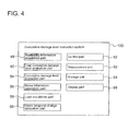
- FIG. 4 is a diagram of a configuration example of a cumulative damage level evaluation system according to one embodiment.
- the cumulative damage level evaluation system 100 illustrated in FIG. 4 includes an availability information acquisition part 48 and a total cumulative damage level evaluation part 50.
- the operation-ration information acquisition part 48 is configured to obtain availability information which indicates an availability of each hydraulic chamber 30 in the entire evaluation period (see FIGs. 2 and 3 ).
- the total cumulative damage level evaluation part 50 is configured to evaluate the total cumulative damage level of each evaluation point of the cylinder block 24 (see FIGs. 2 and 3 ) over the entire evaluation period based on the availability information obtained by the availability information acquisition part 48.
- the stress distribution in the cylinder block 24 in the hydraulic pump 8 varies in accordance with the operation state of each of the hydraulic chambers 30.
- the availability of each hydraulic chamber 30 over the entire evaluation period affects the total cumulative damage level over the entire evaluation period at each position in the cylinder block 24.
- the availability information indicating the availability of each hydraulic chamber 30 in the entire evaluation period is obtained by the availability information acquisition part 48, and the total cumulative damage level over the entire evaluation period of each evaluation point of the cylinder block 24 is evaluated by the total cumulative damage level evaluation part based on the availability information. In this way, it is possible to evaluate the total cumulative damage level of each evaluation point of the cylinder block 24 in the entire evaluation period, appropriately taking account of the operation state of each hydraulic chamber 30 in the entire evaluation period.
- An evaluation period here may be a period of time corresponding to the design product lifetime of the cylinder block 24, a cumulative operation period of the cylinder block 24 until the evaluation time (current time), or a sum of the cumulative operation period and a period from the current time to the next maintenance.
- the availability information acquisition part 48 may obtain an availability actually measured by a measurement unit 62, or may obtain the availability from a storage unit storing an availability based on prediction when occurrence frequency of output of the hydraulic pump 8 is predictable from statistical data of wind condition or the like.
- the cumulative damage level evaluation system 100 further includes a control part 52 configured to control at least one of the plurality of high pressure valves 36 or the plurality of low pressure valves 38 in accordance with the operation pattern of the hydraulic chambers 30 in the cylinder block 24 (see FIGs. 2 and 3 ).
- F(x) (n - x) / n) every unit period (for instance, every single rotation of the rotation shaft of the hydraulic pump 8).
- n is the total number of the hydraulic chambers 30
- x is the number of hydraulic chambers 30 that maintain a state in which the high pressure valve 36 is closed and the low pressure valve 38 is open during a cycle in which the piston 20 moves from the bottom dead center to the top dead center and returns again to the bottom dead center.
- control part 52 is configured to determine, when the total cumulative damage level over the entire evaluation period of at least one evaluation point of the cylinder block 24 is greater than a threshold value, an operation pattern whereby it is possible to avoid stress concentration to the evaluation point at which the cumulative damage level is greater than the threshold value.
- the control part 52 is configured to generate a notification signal for warning when an increasing speed of the total cumulative damage level over the entire evaluation period of at least one evaluation point of the cylinder block 24 is greater than a threshold value.
- the cumulative damage level evaluation system 100 further includes a cumulative damage level calculation part 54 for calculating a cumulative damage level DF F(X) of each evaluation point for every ratio F(x) in a unit period (for instance, every single rotation of the rotation shaft of the hydraulic pump 8).
- the availability information acquisition part 48 is configured to obtain availability information including occurrence frequency f F(x) (see FIG. 5 ) of each ratio F(x) in an entire evaluation period.
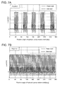
- FIG. 5 is a diagram, if a unit period is a period (single cycle) corresponding to a single rotation of the rotation shaft of the hydraulic pump 8, illustrating the number of rotations of the rotation shaft of the hydraulic pump 8 corresponding to a period in which each ratio F (x) above is present in the entire evaluation period.
- the total cumulative damage level evaluation part 50 is configured to calculate a total cumulative damage level D Ftotal , which is a sum from an entire range of 0 ⁇ F(x) ⁇ 1 of products of the cumulative damage level DF F(x) of each evaluation point for each ratio F(x) in a unit period and occurrence frequency f F(x) of each ratio F(x) in an entire evaluation period.
- the cumulative damage level evaluation system 100 further includes a stress-information calculation part 56 configured to calculate occurrence frequency of a stress average value and a stress amplitude of each evaluation point of the cylinder block 24 for every ratio F(x) in a unit period by the rainflow process, based on information indicating a temporal change in stress for every ratio F(x) in a unit period of each evaluation point of the cylinder block 24.
- the cumulative damage level calculation part 54 is configured to calculate a cumulative damage level DF F(X) based on the calculation result of the stress-information calculation part 56 and a fatigue-strength chart corresponding to a material of each evaluation point of the cylinder block 24.
- the cumulative damage level calculation part 54 may convert the stress average value and the stress amplitude calculated by the stress-information calculation part 56 into an equivalent stress amplitude (a stress amplitude that gives an equivalent damage level while an average stress is zero) using a Goodman chart, for instance.
- the cumulative damage level calculation part 54 calculates the cumulative damage level DF F(X) from the following expression (equation 2) using a damage repetition number Nf i that is given from the fatigue-strength chart and the occurrence frequency N i of the equivalent stress amplitude ⁇ i .
- D ⁇ F F x ⁇ Ni / Nf i
- the fatigue-strength chart indicates a relationship between damage and the number of repetition of the stress amplitude ⁇ i , as illustrated in FIG. 6 .
- the fatigue-strength chart may be stored in the storage unit 64 and read out when needed.
- the cumulative damage level evaluation system 100 further includes a load acquisition part 58 configured to obtain a temporal change of a plurality of loads applied to the cylinder block 24 for every ratio F(x) in the unit period.
- the plurality of loads includes, for instance, load modes such as a load due to the differential pressure across each high pressure valve 36, a load due to the differential pressure across each low pressure valve 38, a piston load, a side load, a load due to a boost pressure of oil to the hydraulic pump 8, and a load due to a drain pressure (e.g. atmospheric pressure) from the hydraulic pump 8 to an oil tank (not illustrated).
- a piston load and a side load respectively refer to forces in the radial direction and in the circumferential direction of the hydraulic pump 8 that the cylinders 22 receive from the pistons 20 in accordance with reciprocating motion of the pistons 20.
- the cumulative damage level evaluation system 100 further includes a stress temporal-change calculation part 60 configured to calculate information that indicates a temporal change in stress for every ratio F(x) in a unit period at each evaluation point of the cylinder block 24 based on: stress generated on each evaluation point of the cylinder block 24 analyzed by the finite element method (FEM) on each unit load of a plurality of loads; and a temporal change in the plurality of loads obtained by the load acquisition part 58 for each ratio F(x).
- FEM finite element method
- the cumulative damage level evaluation system 100 further includes at least one of a measurement unit 62 for measuring a temporal change in a plurality of loads for every ratio F(x) or a storage unit 64 that stores the temporal change in a plurality of loads for every ratio F(x).
- the load acquisition part 58 is configured to obtain a temporal change in a plurality of loads for every ratio F(x) from the measurement unit 62 or the storage unit 64.
- the stress temporal-change calculation part 60 calculates the temporal change in stress for every ratio F(x) in a unit period at each evaluation point of the cylinder block 24, based on the temporal change (see FIG. 7 ) in the plurality of loads obtained by the load acquisition part 58 for every ratio F(x) in a unit period and an analysis result of S11.
- a rainflow process is performed on the temporal change in stress for every ratio F(x) in a unit period at each evaluation point of the cylinder block 24, and the stress information calculation part 56 calculates occurrence frequency of a stress average value and a stress amplitude of each evaluation point of the cylinder block 24 for every ratio F(x) in a unit period.
- the cumulative damage level calculation part 54 calculates a cumulative damage level DF F(x) of each evaluation point for every ratio F(x) in a unit period based on the calculation result of the stress information calculation part 56 and a fatigue-strength chart (see FIG. 6 ) corresponding to a material of each evaluation point of the cylinder block 24.
- the cumulative damage level DF F(x) may be calculated after the stress average value and the stress amplitude, which are the calculation results of the stress information calculation part 56, have been converted into an equivalent stress amplitude using a Goodman chart or the like, as described above.
- the total cumulative damage level evaluation part 50 evaluates the total cumulative damage level DF total over the entire evaluation period of each evaluation point of the cylinder block 24 from the above expression (equation 1), based on occurrence frequency f F(x) (see FIG. 5 ) of each ratio F(x) in the entire evaluation period obtained by the availability information acquisition part 48 and the above cumulative damage level DF F(x) calculated by the cumulative damage level calculation part 54.
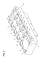
- FIG. 9 is a schematic perspective view of the cylinder block body 34 illustrated in FIGs. 2 and 3 .
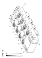
- FIG. 10 is a diagram illustrating the total cumulative damage levels DF total of each evaluation point of the cylinder block body 34 over the entire evaluation period as a gray-scale image.
- the total cumulative damage level DF total over the entire evaluation period of each evaluation point may be visualized by indicating the same on a display part 66 (see FIG. 4 ) as a gray-scale image or a color-coded image.
- a gray-scale image or a color-coded image With the total cumulative damage level DF total visualized by a gray-scale image or a color-coded image, it is possible to easily determine a spot that needs to be intensively checked during maintenance for a crack or breakage, and to improve efficiency of maintenance.
- the total cumulative damage levels DF total are high at high-pressure valve attachment parts 68 and low-pressure valve attachment parts 70 of the cylinder block body 34. This is due to loads caused by differential pressures across the high-pressure valves 36 and across the low pressure valves 38.
- a target of evaluation is not limited to the cylinder block body 34, and the entire cylinder block 24 illustrated in FIGs. 2 and 3 may be evaluated.
- a target of evaluation (evaluation point) may include a portion of a high pressure valve 36 or a portion of a low pressure valve 38 illustrated in FIGs. 2 and 3 , a portion of a cylinder 22, or a bolt attachment part 72 or a groove 74 illustrated in FIG. 10 , for instance.
- the control part 52 determines whether the increasing speed of the total cumulative damage level DF total of at least one evaluation point is greater than a threshold value. In S16, if it is determined that the increasing speed is greater than the threshold value, the control part 52 generates a notification signal for warning and starts an alarm in response to the notification signal in S17. In one embodiment, after the alarm is started, the control part 52 may perform a control for avoiding stress concentration to the at least one evaluation point at which the increasing speed is greater than the threshold value. In S16, if it is determined that the increasing speed is not greater than the threshold value, the control part 52 determines whether the total cumulative damage level DF total of the at least one evaluation point over the entire evaluation period is greater than the threshold value in S19.
- the control part 52 performs a control for avoiding stress concentration to the at least one evaluation point at which the total cumulative damage level DF total is greater than the threshold value in S18.
- the process returns to S15 and the above flow is repeated.
- control part 52 since the control part 52 generates a notification signal for warning, it is possible to perform an appropriate measure such as shutdown and maintenance of the hydraulic pump 8 in accordance with the warning.
- the above cumulative damage level evaluation system 100 may be included in the wind turbine power generating apparatus 1, or may be provided as a system separate from the wind turbine power generating apparatus 1. Further, only a part (for instance, the control part 52, the measurement unit 62, and the storage unit 64 in FIG. 4 ) of the cumulative damage level evaluation system 100 may be included in the wind turbine power generating apparatus 1, and other configuration of the cumulative damage level evaluation system 100 may be provided separately from the wind turbine power generating apparatus 1.
Landscapes
- Engineering & Computer Science (AREA)
- General Engineering & Computer Science (AREA)
- Mechanical Engineering (AREA)
- Combustion & Propulsion (AREA)
- Sustainable Energy (AREA)
- Chemical & Material Sciences (AREA)
- Sustainable Development (AREA)
- Life Sciences & Earth Sciences (AREA)
- Power Engineering (AREA)
- Physics & Mathematics (AREA)
- General Physics & Mathematics (AREA)
- Automation & Control Theory (AREA)
- Wind Motors (AREA)
Applications Claiming Priority (1)
| Application Number | Priority Date | Filing Date | Title |
|---|---|---|---|
| JP2014115265A JP6177192B2 (ja) | 2014-06-03 | 2014-06-03 | 累積損傷度評価システム、再生エネルギー型発電装置、累積損傷度評価方法及び油圧機械の制御方法 |
Publications (2)
| Publication Number | Publication Date |
|---|---|
| EP2952781A1 true EP2952781A1 (de) | 2015-12-09 |
| EP2952781B1 EP2952781B1 (de) | 2018-02-28 |
Family
ID=53719604
Family Applications (1)
| Application Number | Title | Priority Date | Filing Date |
|---|---|---|---|
| EP15169755.4A Not-in-force EP2952781B1 (de) | 2014-06-03 | 2015-05-29 | Kumulatives beschädigungsgradbeurteilungssystem und verfahren |
Country Status (2)
| Country | Link |
|---|---|
| EP (1) | EP2952781B1 (de) |
| JP (1) | JP6177192B2 (de) |
Families Citing this family (2)
| Publication number | Priority date | Publication date | Assignee | Title |
|---|---|---|---|---|
| JP2019085924A (ja) * | 2017-11-07 | 2019-06-06 | 株式会社日立製作所 | 風力発電システム |
| JP7762350B2 (ja) * | 2021-10-04 | 2025-10-30 | マツダ株式会社 | 負荷データ分析方法、装置及びプログラム |
Citations (9)
| Publication number | Priority date | Publication date | Assignee | Title |
|---|---|---|---|---|
| JPS57191483A (en) * | 1981-05-21 | 1982-11-25 | Toyo Electric Mfg Co Ltd | Apparatus for controlling operation of hydraulic pump device |
| DE19730492A1 (de) * | 1997-07-16 | 1999-02-25 | Sauer Sundstrand Gmbh & Co | Digitales Typenschild für elektrisch und hydraulisch verstellbare hydrostatische Antriebe |
| US20050262838A1 (en) * | 2004-05-21 | 2005-12-01 | Masato Kageyama | Hydraulic machine, system for monitoring health of hydraulic machine, and method thereof |
| WO2006124746A2 (en) * | 2005-05-16 | 2006-11-23 | Miller Davis J | System and method for power pump performance monitoring and analysis |
| DE102005059564A1 (de) * | 2005-12-13 | 2007-06-14 | Brueninghaus Hydromatik Gmbh | Vorrichtung und Verfahren zur Zustandsüberwachung bei hydrostatischen Verdrängereinheiten |
| WO2012000506A2 (en) * | 2010-06-28 | 2012-01-05 | Vestas Wind Systems A/S | A method for performing condition monitoring in a wind farm |
| WO2012164789A1 (en) * | 2011-05-30 | 2012-12-06 | Mitsubishi Heavy Industries, Ltd. | Power generating apparatus of renewable energy type and operation method thereof |
| EP2631477A2 (de) * | 2012-02-23 | 2013-08-28 | Mitsubishi Heavy Industries, Ltd. | Überwachungsverfahren und System für einen Windturbinengenerator |
| WO2014002522A1 (ja) | 2012-06-29 | 2014-01-03 | 三菱重工業株式会社 | 油圧ポンプ及びそのメンテナンス方法、並びに風力発電装置 |
Family Cites Families (1)
| Publication number | Priority date | Publication date | Assignee | Title |
|---|---|---|---|---|
| JP2013124565A (ja) * | 2011-12-13 | 2013-06-24 | Omron Corp | 診断装置および診断方法 |
-
2014
- 2014-06-03 JP JP2014115265A patent/JP6177192B2/ja not_active Expired - Fee Related
-
2015
- 2015-05-29 EP EP15169755.4A patent/EP2952781B1/de not_active Not-in-force
Patent Citations (9)
| Publication number | Priority date | Publication date | Assignee | Title |
|---|---|---|---|---|
| JPS57191483A (en) * | 1981-05-21 | 1982-11-25 | Toyo Electric Mfg Co Ltd | Apparatus for controlling operation of hydraulic pump device |
| DE19730492A1 (de) * | 1997-07-16 | 1999-02-25 | Sauer Sundstrand Gmbh & Co | Digitales Typenschild für elektrisch und hydraulisch verstellbare hydrostatische Antriebe |
| US20050262838A1 (en) * | 2004-05-21 | 2005-12-01 | Masato Kageyama | Hydraulic machine, system for monitoring health of hydraulic machine, and method thereof |
| WO2006124746A2 (en) * | 2005-05-16 | 2006-11-23 | Miller Davis J | System and method for power pump performance monitoring and analysis |
| DE102005059564A1 (de) * | 2005-12-13 | 2007-06-14 | Brueninghaus Hydromatik Gmbh | Vorrichtung und Verfahren zur Zustandsüberwachung bei hydrostatischen Verdrängereinheiten |
| WO2012000506A2 (en) * | 2010-06-28 | 2012-01-05 | Vestas Wind Systems A/S | A method for performing condition monitoring in a wind farm |
| WO2012164789A1 (en) * | 2011-05-30 | 2012-12-06 | Mitsubishi Heavy Industries, Ltd. | Power generating apparatus of renewable energy type and operation method thereof |
| EP2631477A2 (de) * | 2012-02-23 | 2013-08-28 | Mitsubishi Heavy Industries, Ltd. | Überwachungsverfahren und System für einen Windturbinengenerator |
| WO2014002522A1 (ja) | 2012-06-29 | 2014-01-03 | 三菱重工業株式会社 | 油圧ポンプ及びそのメンテナンス方法、並びに風力発電装置 |
Also Published As
| Publication number | Publication date |
|---|---|
| JP2015229939A (ja) | 2015-12-21 |
| EP2952781B1 (de) | 2018-02-28 |
| JP6177192B2 (ja) | 2017-08-09 |
Similar Documents
| Publication | Publication Date | Title |
|---|---|---|
| EP2631477A2 (de) | Überwachungsverfahren und System für einen Windturbinengenerator | |
| EP2440776B1 (de) | Strömungsmaschine mit mehrflächenringnocke | |
| EP3135907A1 (de) | Hydraulische maschine, verfahren zum betrieb davon und stromerzeugungsvorrichtung vom typ der erneuerbaren energien | |
| EP2889480B1 (de) | Diagnosesystem und Diagnoseverfahren für eine hydraulische Maschine, und hydraulisches Getriebe und Windturbinengenerator | |
| EP2952781B1 (de) | Kumulatives beschädigungsgradbeurteilungssystem und verfahren | |
| EP2889710B1 (de) | Diagnoseverfahren und Diagnosevorrichtung für hydraulische Maschine | |
| US20180306170A1 (en) | Membrane fluid pump | |
| EP3242029B1 (de) | Verfahren und vorrichtung zur diagnose einer hydraulischen maschine, vorrichtung zur erzeugung von strom aus erneuerbaren energie und verfahren zur diagnose davon | |
| EP2821638B1 (de) | Generator für erneuerbare energien | |
| EP2955374B1 (de) | Radialkolbenhydraulikmaschine und windturbinenstromerzeugungsvorrichtung | |
| US20170045062A1 (en) | Hydraulic flat cylinder, hydraulic lifting cushion and use thereof, and method for aligning a generator | |
| EP3112677A3 (de) | Stromerzeugungsvorrichtung für erneuerbare energien, motorsteuerung und verfahren zum betrieb einer stromerzeugungsvorrichtung für erneuerbare energien | |
| EP3048339A1 (de) | Hydraulisches system, windturbinenstromerzeugungsvorrichtung und betriebsverfahren dafür | |
| EP3211276A1 (de) | Diagnosesystem und -verfahren für eine hydraulische maschine, hydraulische maschine und vorrichtung zur erzeugung erneuerbarer energie | |
| EP3075950A1 (de) | Hydraulikmaschine und vorrichtung zur stromerzeugung aus erneuerbaren energien | |
| EP2749768A1 (de) | Radialkolbenhydraulikmaschine und Windturbinengenerator | |
| EP2821648A1 (de) | Hydraulikmaschine und vorrichtung zur erzeugung von erneuerbarer energie | |
| EP3141748B1 (de) | Hydraulische maschine vom radialkolbentyp und windturbinenstromerzeugungsvorrichtung | |
| EP3211275B1 (de) | Verfahren und system zur diagnose einer hydraulischen maschine, hydraulische maschine und leistungserzeugungsvorrichtung für erneuerbare energie | |
| EP3211228B1 (de) | Hydraulikmaschine und windturbinenstromerzeugungsvorrichtung | |
| KR200482285Y1 (ko) | 레이디얼 피스톤형 유압기기용 예압 조절장치 | |
| EP3199808B1 (de) | Hydraulikmaschine, ringnocken und vorrichtung zur erzeugung von strom vom typ der erneuerbaren energie | |
| EP3287636A1 (de) | Betriebsverfahren und betriebssteuerungssystem für einen hydraulischen motor, hydraulisches getriebe und vorrichtung zur erzeugung erneuerbarer energie | |
| EP3211232A1 (de) | System und verfahren zur diagnose einer hydraulischen maschine, hydraulische maschine, hydraulische übertragung und leistungserzeugungsvorrichtung mit erneuerbarer energie | |
| Wu et al. | Analysis of pulsation of linear hydraulic motor |
Legal Events
| Date | Code | Title | Description |
|---|---|---|---|
| PUAI | Public reference made under article 153(3) epc to a published international application that has entered the european phase |
Free format text: ORIGINAL CODE: 0009012 |
|
| AK | Designated contracting states |
Kind code of ref document: A1 Designated state(s): AL AT BE BG CH CY CZ DE DK EE ES FI FR GB GR HR HU IE IS IT LI LT LU LV MC MK MT NL NO PL PT RO RS SE SI SK SM TR |
|
| AX | Request for extension of the european patent |
Extension state: BA ME |
|
| 17P | Request for examination filed |
Effective date: 20160519 |
|
| RBV | Designated contracting states (corrected) |
Designated state(s): AL AT BE BG CH CY CZ DE DK EE ES FI FR GB GR HR HU IE IS IT LI LT LU LV MC MK MT NL NO PL PT RO RS SE SI SK SM TR |
|
| 17Q | First examination report despatched |
Effective date: 20170719 |
|
| GRAP | Despatch of communication of intention to grant a patent |
Free format text: ORIGINAL CODE: EPIDOSNIGR1 |
|
| RIC1 | Information provided on ipc code assigned before grant |
Ipc: F16H 57/01 20120101AFI20171031BHEP Ipc: F03D 13/00 20160101ALI20171031BHEP Ipc: G05B 23/02 20060101ALI20171031BHEP Ipc: F03D 15/00 20160101ALI20171031BHEP Ipc: F03D 9/00 20160101ALI20171031BHEP |
|
| INTG | Intention to grant announced |
Effective date: 20171127 |
|
| GRAS | Grant fee paid |
Free format text: ORIGINAL CODE: EPIDOSNIGR3 |
|
| GRAA | (expected) grant |
Free format text: ORIGINAL CODE: 0009210 |
|
| AK | Designated contracting states |
Kind code of ref document: B1 Designated state(s): AL AT BE BG CH CY CZ DE DK EE ES FI FR GB GR HR HU IE IS IT LI LT LU LV MC MK MT NL NO PL PT RO RS SE SI SK SM TR |
|
| REG | Reference to a national code |
Ref country code: GB Ref legal event code: FG4D Ref country code: CH Ref legal event code: EP |
|
| REG | Reference to a national code |
Ref country code: AT Ref legal event code: REF Ref document number: 974525 Country of ref document: AT Kind code of ref document: T Effective date: 20180315 |
|
| REG | Reference to a national code |
Ref country code: IE Ref legal event code: FG4D |
|
| REG | Reference to a national code |
Ref country code: DE Ref legal event code: R096 Ref document number: 602015008245 Country of ref document: DE |
|
| REG | Reference to a national code |
Ref country code: FR Ref legal event code: PLFP Year of fee payment: 4 |
|
| REG | Reference to a national code |
Ref country code: NL Ref legal event code: MP Effective date: 20180228 |
|
| REG | Reference to a national code |
Ref country code: LT Ref legal event code: MG4D |
|
| REG | Reference to a national code |
Ref country code: AT Ref legal event code: MK05 Ref document number: 974525 Country of ref document: AT Kind code of ref document: T Effective date: 20180228 |
|
| PG25 | Lapsed in a contracting state [announced via postgrant information from national office to epo] |
Ref country code: CY Free format text: LAPSE BECAUSE OF FAILURE TO SUBMIT A TRANSLATION OF THE DESCRIPTION OR TO PAY THE FEE WITHIN THE PRESCRIBED TIME-LIMIT Effective date: 20180228 Ref country code: NL Free format text: LAPSE BECAUSE OF FAILURE TO SUBMIT A TRANSLATION OF THE DESCRIPTION OR TO PAY THE FEE WITHIN THE PRESCRIBED TIME-LIMIT Effective date: 20180228 Ref country code: HR Free format text: LAPSE BECAUSE OF FAILURE TO SUBMIT A TRANSLATION OF THE DESCRIPTION OR TO PAY THE FEE WITHIN THE PRESCRIBED TIME-LIMIT Effective date: 20180228 Ref country code: LT Free format text: LAPSE BECAUSE OF FAILURE TO SUBMIT A TRANSLATION OF THE DESCRIPTION OR TO PAY THE FEE WITHIN THE PRESCRIBED TIME-LIMIT Effective date: 20180228 Ref country code: ES Free format text: LAPSE BECAUSE OF FAILURE TO SUBMIT A TRANSLATION OF THE DESCRIPTION OR TO PAY THE FEE WITHIN THE PRESCRIBED TIME-LIMIT Effective date: 20180228 Ref country code: FI Free format text: LAPSE BECAUSE OF FAILURE TO SUBMIT A TRANSLATION OF THE DESCRIPTION OR TO PAY THE FEE WITHIN THE PRESCRIBED TIME-LIMIT Effective date: 20180228 Ref country code: NO Free format text: LAPSE BECAUSE OF FAILURE TO SUBMIT A TRANSLATION OF THE DESCRIPTION OR TO PAY THE FEE WITHIN THE PRESCRIBED TIME-LIMIT Effective date: 20180528 |
|
| PG25 | Lapsed in a contracting state [announced via postgrant information from national office to epo] |
Ref country code: GR Free format text: LAPSE BECAUSE OF FAILURE TO SUBMIT A TRANSLATION OF THE DESCRIPTION OR TO PAY THE FEE WITHIN THE PRESCRIBED TIME-LIMIT Effective date: 20180529 Ref country code: BG Free format text: LAPSE BECAUSE OF FAILURE TO SUBMIT A TRANSLATION OF THE DESCRIPTION OR TO PAY THE FEE WITHIN THE PRESCRIBED TIME-LIMIT Effective date: 20180528 Ref country code: AT Free format text: LAPSE BECAUSE OF FAILURE TO SUBMIT A TRANSLATION OF THE DESCRIPTION OR TO PAY THE FEE WITHIN THE PRESCRIBED TIME-LIMIT Effective date: 20180228 Ref country code: RS Free format text: LAPSE BECAUSE OF FAILURE TO SUBMIT A TRANSLATION OF THE DESCRIPTION OR TO PAY THE FEE WITHIN THE PRESCRIBED TIME-LIMIT Effective date: 20180228 Ref country code: SE Free format text: LAPSE BECAUSE OF FAILURE TO SUBMIT A TRANSLATION OF THE DESCRIPTION OR TO PAY THE FEE WITHIN THE PRESCRIBED TIME-LIMIT Effective date: 20180228 Ref country code: LV Free format text: LAPSE BECAUSE OF FAILURE TO SUBMIT A TRANSLATION OF THE DESCRIPTION OR TO PAY THE FEE WITHIN THE PRESCRIBED TIME-LIMIT Effective date: 20180228 |
|
| PG25 | Lapsed in a contracting state [announced via postgrant information from national office to epo] |
Ref country code: EE Free format text: LAPSE BECAUSE OF FAILURE TO SUBMIT A TRANSLATION OF THE DESCRIPTION OR TO PAY THE FEE WITHIN THE PRESCRIBED TIME-LIMIT Effective date: 20180228 Ref country code: PL Free format text: LAPSE BECAUSE OF FAILURE TO SUBMIT A TRANSLATION OF THE DESCRIPTION OR TO PAY THE FEE WITHIN THE PRESCRIBED TIME-LIMIT Effective date: 20180228 Ref country code: RO Free format text: LAPSE BECAUSE OF FAILURE TO SUBMIT A TRANSLATION OF THE DESCRIPTION OR TO PAY THE FEE WITHIN THE PRESCRIBED TIME-LIMIT Effective date: 20180228 Ref country code: AL Free format text: LAPSE BECAUSE OF FAILURE TO SUBMIT A TRANSLATION OF THE DESCRIPTION OR TO PAY THE FEE WITHIN THE PRESCRIBED TIME-LIMIT Effective date: 20180228 Ref country code: IT Free format text: LAPSE BECAUSE OF FAILURE TO SUBMIT A TRANSLATION OF THE DESCRIPTION OR TO PAY THE FEE WITHIN THE PRESCRIBED TIME-LIMIT Effective date: 20180228 |
|
| REG | Reference to a national code |
Ref country code: DE Ref legal event code: R097 Ref document number: 602015008245 Country of ref document: DE |
|
| PG25 | Lapsed in a contracting state [announced via postgrant information from national office to epo] |
Ref country code: CZ Free format text: LAPSE BECAUSE OF FAILURE TO SUBMIT A TRANSLATION OF THE DESCRIPTION OR TO PAY THE FEE WITHIN THE PRESCRIBED TIME-LIMIT Effective date: 20180228 Ref country code: DK Free format text: LAPSE BECAUSE OF FAILURE TO SUBMIT A TRANSLATION OF THE DESCRIPTION OR TO PAY THE FEE WITHIN THE PRESCRIBED TIME-LIMIT Effective date: 20180228 Ref country code: SM Free format text: LAPSE BECAUSE OF FAILURE TO SUBMIT A TRANSLATION OF THE DESCRIPTION OR TO PAY THE FEE WITHIN THE PRESCRIBED TIME-LIMIT Effective date: 20180228 Ref country code: SK Free format text: LAPSE BECAUSE OF FAILURE TO SUBMIT A TRANSLATION OF THE DESCRIPTION OR TO PAY THE FEE WITHIN THE PRESCRIBED TIME-LIMIT Effective date: 20180228 |
|
| REG | Reference to a national code |
Ref country code: CH Ref legal event code: PL |
|
| PLBE | No opposition filed within time limit |
Free format text: ORIGINAL CODE: 0009261 |
|
| STAA | Information on the status of an ep patent application or granted ep patent |
Free format text: STATUS: NO OPPOSITION FILED WITHIN TIME LIMIT |
|
| REG | Reference to a national code |
Ref country code: BE Ref legal event code: MM Effective date: 20180531 |
|
| PG25 | Lapsed in a contracting state [announced via postgrant information from national office to epo] |
Ref country code: MC Free format text: LAPSE BECAUSE OF FAILURE TO SUBMIT A TRANSLATION OF THE DESCRIPTION OR TO PAY THE FEE WITHIN THE PRESCRIBED TIME-LIMIT Effective date: 20180228 |
|
| 26N | No opposition filed |
Effective date: 20181129 |
|
| REG | Reference to a national code |
Ref country code: IE Ref legal event code: MM4A |
|
| PG25 | Lapsed in a contracting state [announced via postgrant information from national office to epo] |
Ref country code: CH Free format text: LAPSE BECAUSE OF NON-PAYMENT OF DUE FEES Effective date: 20180531 Ref country code: LI Free format text: LAPSE BECAUSE OF NON-PAYMENT OF DUE FEES Effective date: 20180531 Ref country code: SI Free format text: LAPSE BECAUSE OF FAILURE TO SUBMIT A TRANSLATION OF THE DESCRIPTION OR TO PAY THE FEE WITHIN THE PRESCRIBED TIME-LIMIT Effective date: 20180228 |
|
| PG25 | Lapsed in a contracting state [announced via postgrant information from national office to epo] |
Ref country code: LU Free format text: LAPSE BECAUSE OF NON-PAYMENT OF DUE FEES Effective date: 20180529 |
|
| PG25 | Lapsed in a contracting state [announced via postgrant information from national office to epo] |
Ref country code: IE Free format text: LAPSE BECAUSE OF NON-PAYMENT OF DUE FEES Effective date: 20180529 |
|
| PG25 | Lapsed in a contracting state [announced via postgrant information from national office to epo] |
Ref country code: BE Free format text: LAPSE BECAUSE OF NON-PAYMENT OF DUE FEES Effective date: 20180531 |
|
| PG25 | Lapsed in a contracting state [announced via postgrant information from national office to epo] |
Ref country code: MT Free format text: LAPSE BECAUSE OF NON-PAYMENT OF DUE FEES Effective date: 20180529 |
|
| PG25 | Lapsed in a contracting state [announced via postgrant information from national office to epo] |
Ref country code: TR Free format text: LAPSE BECAUSE OF FAILURE TO SUBMIT A TRANSLATION OF THE DESCRIPTION OR TO PAY THE FEE WITHIN THE PRESCRIBED TIME-LIMIT Effective date: 20180228 |
|
| PG25 | Lapsed in a contracting state [announced via postgrant information from national office to epo] |
Ref country code: PT Free format text: LAPSE BECAUSE OF FAILURE TO SUBMIT A TRANSLATION OF THE DESCRIPTION OR TO PAY THE FEE WITHIN THE PRESCRIBED TIME-LIMIT Effective date: 20180228 |
|
| PG25 | Lapsed in a contracting state [announced via postgrant information from national office to epo] |
Ref country code: HU Free format text: LAPSE BECAUSE OF FAILURE TO SUBMIT A TRANSLATION OF THE DESCRIPTION OR TO PAY THE FEE WITHIN THE PRESCRIBED TIME-LIMIT; INVALID AB INITIO Effective date: 20150529 Ref country code: MK Free format text: LAPSE BECAUSE OF NON-PAYMENT OF DUE FEES Effective date: 20180228 |
|
| PG25 | Lapsed in a contracting state [announced via postgrant information from national office to epo] |
Ref country code: IS Free format text: LAPSE BECAUSE OF FAILURE TO SUBMIT A TRANSLATION OF THE DESCRIPTION OR TO PAY THE FEE WITHIN THE PRESCRIBED TIME-LIMIT Effective date: 20180628 |
|
| REG | Reference to a national code |
Ref country code: DE Ref legal event code: R082 Ref document number: 602015008245 Country of ref document: DE Representative=s name: CBDL PATENTANWAELTE GBR, DE |
|
| REG | Reference to a national code |
Ref country code: FR Ref legal event code: PLFP Year of fee payment: 9 |
|
| PGFP | Annual fee paid to national office [announced via postgrant information from national office to epo] |
Ref country code: FR Payment date: 20230411 Year of fee payment: 9 Ref country code: DE Payment date: 20230404 Year of fee payment: 9 |
|
| PGFP | Annual fee paid to national office [announced via postgrant information from national office to epo] |
Ref country code: GB Payment date: 20230406 Year of fee payment: 9 |
|
| REG | Reference to a national code |
Ref country code: DE Ref legal event code: R119 Ref document number: 602015008245 Country of ref document: DE |
|
| GBPC | Gb: european patent ceased through non-payment of renewal fee |
Effective date: 20240529 |
|
| PG25 | Lapsed in a contracting state [announced via postgrant information from national office to epo] |
Ref country code: DE Free format text: LAPSE BECAUSE OF NON-PAYMENT OF DUE FEES Effective date: 20241203 |
|
| PG25 | Lapsed in a contracting state [announced via postgrant information from national office to epo] |
Ref country code: FR Free format text: LAPSE BECAUSE OF NON-PAYMENT OF DUE FEES Effective date: 20240531 |
|
| PG25 | Lapsed in a contracting state [announced via postgrant information from national office to epo] |
Ref country code: GB Free format text: LAPSE BECAUSE OF NON-PAYMENT OF DUE FEES Effective date: 20240529 |