EP2952782A1 - Getriebe mit mitteln zur berechnung der übersetzung - Google Patents
Getriebe mit mitteln zur berechnung der übersetzung Download PDFInfo
- Publication number
- EP2952782A1 EP2952782A1 EP15169407.2A EP15169407A EP2952782A1 EP 2952782 A1 EP2952782 A1 EP 2952782A1 EP 15169407 A EP15169407 A EP 15169407A EP 2952782 A1 EP2952782 A1 EP 2952782A1
- Authority
- EP
- European Patent Office
- Prior art keywords
- gear ratio
- ratio step
- timer
- gear
- current
- Prior art date
- Legal status (The legal status is an assumption and is not a legal conclusion. Google has not performed a legal analysis and makes no representation as to the accuracy of the status listed.)
- Granted
Links
Images


Classifications
-
- F—MECHANICAL ENGINEERING; LIGHTING; HEATING; WEAPONS; BLASTING
- F16—ENGINEERING ELEMENTS AND UNITS; GENERAL MEASURES FOR PRODUCING AND MAINTAINING EFFECTIVE FUNCTIONING OF MACHINES OR INSTALLATIONS; THERMAL INSULATION IN GENERAL
- F16H—GEARING
- F16H59/00—Control inputs to control units of change-speed- or reversing-gearings for conveying rotary motion
- F16H59/68—Inputs being a function of gearing status
- F16H59/70—Inputs being a function of gearing status dependent on the ratio established
-
- F—MECHANICAL ENGINEERING; LIGHTING; HEATING; WEAPONS; BLASTING
- F16—ENGINEERING ELEMENTS AND UNITS; GENERAL MEASURES FOR PRODUCING AND MAINTAINING EFFECTIVE FUNCTIONING OF MACHINES OR INSTALLATIONS; THERMAL INSULATION IN GENERAL
- F16H—GEARING
- F16H63/00—Control outputs from the control unit to change-speed- or reversing-gearings for conveying rotary motion or to other devices than the final output mechanism
- F16H63/40—Control outputs from the control unit to change-speed- or reversing-gearings for conveying rotary motion or to other devices than the final output mechanism comprising signals other than signals for actuating the final output mechanisms
- F16H63/42—Ratio indicator devices
-
- F—MECHANICAL ENGINEERING; LIGHTING; HEATING; WEAPONS; BLASTING
- F16—ENGINEERING ELEMENTS AND UNITS; GENERAL MEASURES FOR PRODUCING AND MAINTAINING EFFECTIVE FUNCTIONING OF MACHINES OR INSTALLATIONS; THERMAL INSULATION IN GENERAL
- F16H—GEARING
- F16H59/00—Control inputs to control units of change-speed- or reversing-gearings for conveying rotary motion
- F16H59/68—Inputs being a function of gearing status
- F16H2059/6823—Sensing neutral state of the transmission
-
- F—MECHANICAL ENGINEERING; LIGHTING; HEATING; WEAPONS; BLASTING
- F16—ENGINEERING ELEMENTS AND UNITS; GENERAL MEASURES FOR PRODUCING AND MAINTAINING EFFECTIVE FUNCTIONING OF MACHINES OR INSTALLATIONS; THERMAL INSULATION IN GENERAL
- F16H—GEARING
- F16H59/00—Control inputs to control units of change-speed- or reversing-gearings for conveying rotary motion
- F16H59/68—Inputs being a function of gearing status
- F16H59/70—Inputs being a function of gearing status dependent on the ratio established
- F16H2059/706—Monitoring gear ratio in stepped transmissions, e.g. by calculating the ratio from input and output speed
-
- F—MECHANICAL ENGINEERING; LIGHTING; HEATING; WEAPONS; BLASTING
- F16—ENGINEERING ELEMENTS AND UNITS; GENERAL MEASURES FOR PRODUCING AND MAINTAINING EFFECTIVE FUNCTIONING OF MACHINES OR INSTALLATIONS; THERMAL INSULATION IN GENERAL
- F16H—GEARING
- F16H59/00—Control inputs to control units of change-speed- or reversing-gearings for conveying rotary motion
- F16H59/36—Inputs being a function of speed
- F16H59/38—Inputs being a function of speed of gearing elements
- F16H59/40—Output shaft speed
-
- F—MECHANICAL ENGINEERING; LIGHTING; HEATING; WEAPONS; BLASTING
- F16—ENGINEERING ELEMENTS AND UNITS; GENERAL MEASURES FOR PRODUCING AND MAINTAINING EFFECTIVE FUNCTIONING OF MACHINES OR INSTALLATIONS; THERMAL INSULATION IN GENERAL
- F16H—GEARING
- F16H59/00—Control inputs to control units of change-speed- or reversing-gearings for conveying rotary motion
- F16H59/36—Inputs being a function of speed
- F16H59/38—Inputs being a function of speed of gearing elements
- F16H59/42—Input shaft speed
Definitions
- This invention relates to an automobile transmission, and more specifically, an automobile transmission which can preferably prevent a controller from erroneous detection of a current gear ratio step to rapidly and accurately detect the current gear ratio step regardless of clutch engagement.
- a gear ratio indicating apparatus as described in patent document 1: Publication No. JP2008-39111 , has also been disclosed which, instead of providing the shift position sensors to the gear ratio change mechanism, a current gear ratio step is supposed to be determined based on signals outputted by two rotational speed sensors which are disposed in input shaft side and output shaft side, respectively.
- a gear-position determination apparatus as described in patent document 2 Japan Patent No. 4404096 , has also been disclosed which a current gear ratio step is supposed to be determined based on ratio of an engine revolution and a vehicle speed calculated from signals outputted by an engine revolution sensor and a vehicle speed sensor, respectively.
- a controller such as engine control unit possibly erroneously detects the current gear ratio step and, in worst case, possibly makes the indicating apparatus flash intermittently on and off.
- the controller erroneously detects each of the intermediate gear ratio steps as a current gear ratio step as well.
- a current gear ratio step is supposed to be determined by differential value of vehicle speed in addition to ratio of the engine revolution and vehicle speed.
- the apparatus in the Patent document 2 has a problem that it is hard to accurately detect the current gear ratio step of the transmission.
- the apparatus additionally has another problem that it is hard to prevent the controller from erroneous detection of the current gear ratio step as long as the differential value of vehicle speed does not exceed a given threshold.
- the present invention is achieved to solve the above-mentioned problems.
- the purpose of the present invention is to provide an automobile transmission which can prevent a controller from erroneous detection of a current gear ratio step to rapidly and accurately detect the current gear ratio step regardless of clutch engagement.
- a transmission comprising an input shaft receiving a drive torque transferred via a clutch from a power source; a synchronizer group having a plurality of synchronizer to select one of plural gear sequences; an output shaft transmitting to a final drive gear the drive torque rotationally changed by the selected gear sequence; a gear ratio calculation means for calculating an actual gear ratio based on revolutions of the input and output shafts detected by a first revolution detection means and a second revolution detection means, respectively; a gear ratio map for defining a gear ratio variable allowance range for a gear ratio step; a determination means of gear ratio step for determining a current gear ratio step by the actual gear ratio and the gear ratio variable allowance range; and a detection means of neutral condition for detecting a neutral condition of the gear ratio step; wherein the determination means of gear ratio step including a first timer for measuring a first given time, is configured to make the first timer get started and halt to make a decision of the current gear ratio step while the first timer is activated, when
- the determination means of gear ratio step when making a decision of the current gear ratio step (gear ratio step of currently engaged gear) determined based on the actual gear ratio and gear ratio map, the determination means of gear ratio step is configured to halt to make the decision of current gear ratio step during activation or at completion time of the synchronizer when each of revolutions of the input and output shafts unsteadily fluctuates, by the first timer to halt making a decision of current gear ratio step for a predetermined time.
- the determination means of gear ratio step is prevented from erroneous detection of current gear ratio step. In the result, it becomes to be possible to preferably prevent on-off intermittent indication of the current gear ratio step and temporary indication of the intermediate gear ratio steps in merely passing.
- the determination means of gear ratio step includes a display means of gear ratio step for indicating a status of gear ratio step and is configured to make the display means of gear ratio step not to indicate any current gear ratio steps while the first timer is activated.
- the determination means of gear ratio step is configured to stop the first timer and reset measured time when the gear ratio deviates from the gear ratio variable allowance range of the next step.
- an activating time of the first timer is configured to become longer as gear ratio step goes from a step of high vehicle speed to other step of low vehicle speed.
- the activating time of the first timer is configured to become longer as gear ratio step goes from a step of high vehicle speed to other step of low vehicle speed. In the result, it becomes to be possible to preferably prevent on-off intermittent indication of the current gear ratio step and temporary indication of the intermediate gear ratio steps in merely passing.
- the determination means of gear ratio step including a second timer for measuring a second given time, is configured to make the second timer get started at a time which is earlier when the detection means of neutral condition detects the neutral condition or when the gear ratio deviates from the gear ratio variable allowance range corresponding to the current gear ratio step; and to make the display means of gear ratio step to indicate a gear ratio step immediately before the second timer gets started while the second timer is activated.
- the determination means of gear ratio step is configured to make the second timer get stopped when the first timer gets started.
- the first timer is activated with priority over the second timer. In the result, it becomes to be possible to rapidly indicate a current gear ratio step after each of revolutions of the input and output shafts is stable.
- the determination means of gear ratio step is, by the first timer (delay timer) to halt making a decision of current gear ratio step for a predetermined time, configured to halt to make the decision of current gear ratio step, during activation or at completion time of the synchronizer when each of revolutions of the input and output shafts unsteadily fluctuates.
- the determination means of gear ratio step is prevented from erroneous detection of current gear ratio step. In the result, it becomes to be possible to preferably prevent on-off intermittent indication of the current gear ratio step and temporary indication of the intermediate gear ratio steps in merely passing.
- determination of current gear ratio is supposed to be conducted based on ratio of actual revolutions of the input and output shafts measured by the first and second detection means as well as gear ratio map for defining a gear ratio variable allowance range for each of gear ratio steps.
- gear ratio map for defining a gear ratio variable allowance range for each of gear ratio steps.
- the second timer to keep on indicating a status of gear ratio immediately before gear ratio change, makes shorten uncertain time (blank time) where a current gear ratio is not yet fixed at an early time of the gear ratio change and consequently, with the first timer, it becomes to be possible to more preferably prevent on-off intermittent indication of the current gear ratio step and temporary indication of the intermediate gear ratio steps in merely passing. In the result, a driver comes to feel nothing unnatural with respect to gear ratio change.
- Fig.1 is an explanation drawing to show a configuration of transmission system in accordance with an embodiment of the present invention. It should be noted that, for convenience of explanation, a power source 1 including engine is also shown in the Fig.1 .
- This transmission system 100 includes a clutch portion 2 which connects or disconnects a gear portion 3 and the power source 1 producing drive torque, the gear portion 3 which changes revolution of drive torque transferred from the power source 1, a clutch operation portion 4 for driver to operate the clutch portion 2, a shift operation portion 5 for driver to operate the gear portion 3, a determination apparatus of gear ratio step 6 (as actual gear ratio calculation means and determination means of gear ratio step) performing a prevention process against erroneous detection of gear ratio step in accordance with the present invention, and status display of gear ratio step 7 (as display means of gear ratio step) indicating a status of decided current gear ratio step.
- the prevention process against erroneous detection of gear ratio step is described below in detail with reference to Figs.2 to 6 . Furthermore, each of elements is described below.
- a mechanism of producing the rotational drive torque should not be especially limited.
- Internal combustion including gasoline-powered engine, electrical motor-powered engine or hybrid engine etc. can be preferably applied to the embodiment of the present invention.
- the clutch portion 2 is a hydraulic clutch.
- a driver pushes a clutch pedal 4a downward to cause oil pressure in a clutch master cylinder 4b.
- the oil pressure propagates in a hydraulic pipe 4c and drives a clutch disk driving mechanism having a release cylinder 4d and a release fork 4e.
- Pushing force of a clutch cover 2b over a clutch disk 2a is released by driving force of the release cylinder 4d and fork 4e.
- the clutch disk 2a becomes to be separated from a flywheel 1a.
- Clutch pedal switch 4f is disposed near the clutch pedal 4a and outputs a signal every time driver pushes the clutch pedal 4a downward.
- the gear portion 3 includes a main shaft 3a, a counter shaft 3b and a reverse idle shaft 3c.
- the main shaft 3a includes a gear set M1G to M6G respectively corresponding to 1st gear ratio position "D1" to 6th gear ratio position “D6” of shift operation portion 5 and a reverse drive gear RDrG corresponding to reverse gear position "R” of shift operation portion 5.
- main 1st gear M1G, main 2nd gear M2G and reverse drive gear R are constantly connected for rotation with the main shaft 3a whereas a gear set M3G to M6 is selectively connectable for rotation with the main shaft 3a.
- the counter shaft 3b includes a gear set C1G to C6G respectively meshing with the gear set M1G to M6G and a reverse driven gear RDnG formed on a sleeve (not shown) of 1st- 2nd synchronizer selectively engageable with the main 1st gear M1G or 2nd gear M2G.
- counter 1st gear C1G and counter 2nd gear C2G are selectively connectable for rotation with the counter shaft 3b whereas a gear set C3G,C4G,C5G,C6G is constantly connected for rotation with the counter shaft 3b.
- the reverse idle shaft 3c includes a reverse idle gear RIG meshing with both the reverse drive gear RDrG and driven gear RDnG.
- the idle gear RIG is rotatably supported on the reverse idle shaft 3c.
- 1st-2nd synchronizer selectively connecting the counter 1st gear C1G or 2nd gear C2G to the counter shaft 3b for rotation therewith.
- 3rd-4th synchronizer selectively connecting the 3rd gear M3G or main 4th gear M4G to the main shaft 3a for rotation therewith.
- 5th-6th synchronizer selectively connecting the main 5th gear M5G or main 6th gear M6G to the main shaft 3a for rotation therewith.
- 1st-2nd synchronizer is engaged to connect the counter 1st gear C1G or 2nd gear C2G to the counter shaft 3b
- 1st gear sequence or 2nd gear sequence is established.
- 3rd-4th synchronizer is engaged to connect the main 3rd gear M3G or 4th gear M4G to the main shaft 3a
- 3rd gear sequence or 4th gear sequence is established as well.
- 5th-6th synchronizer is engaged to connect the main 5th gear M5G or 6th gear M6G to the main shaft 3a, 5th gear sequence or 6th gear sequence is established as well.
- each established gear sequence transfers drive torque with a given gear ratio from main shaft 3a to counter shaft 3b.
- the drive torque transferred to the counter shaft 3b is, in turn, transferred to a differential (not shown) through a final drive gear (not shown).
- the main shaft 3a also includes a main revolution sensor 3d for detecting a revolution of the main shaft 3a.
- the revolution of the main shaft 3a may be retrieved from such a gear as main 1st gear M1G, main 2nd gears M2G or reverse drive gear RDrG for rotation synchronized with the main shaft 3a.
- the counter shaft 3b also includes a counter revolution sensor 3e for detecting a revolution of the counter shaft 3b.
- the revolution of the counter shaft 3b may be retrieved from such a gear as any one of counter 3rd to 6th gears C3G to C6G for rotation synchronized with the counter shaft 3b.
- Each of retrieved signals is used for performing a prevention process against erroneous detection of gear ratio step in accordance with an embodiment of the present invention as described below.
- the shift operation portion 5 includes a change lever 5a, a gate portion 5b, a change wire 5c, and a link mechanism 5d for driving respective synchronizers of gear portion 3.
- the link mechanism 5d includes a shift arm (not shown) movable along and rotatable about a shaft, four shift forks (not shown) engaged with respective sleeves (not shown) of the synchronizers, four shift pieces engaged with both the shift arm and shift fork.
- the link mechanism 5d is configured to drive the shift arm move along the shaft to be engaged with one shift piece in response to motion of change lever 5a operated by driver, and in turn the shift arm rotate about the shaft to displace the shift piece in axial direction of the main shaft 3a or counter shaft 3b to drive a synchronizer. Also, in direction perpendicular to axial direction of shift arm is provided a neutral sensor 5e for directly detecting a neutral position of change lever 5a.
- the determination apparatus of gear ratio step 6 determines a current gear ratio step by receiving respective signals Nm,Nc,Pn from the main and counter revolution sensors 3d,3e and neutral sensor 5e and performing a prevention process against erroneous detection of gear ratio step in accordance with an embodiment of the present invention as described below. Note that the determination apparatus of gear ratio step 6 may be in exclusive use instead of shearing use with engine control unit (ECU) as in the embodiment of the present invention.
- ECU engine control unit
- the status display of gear ratio step 7 receives a command from the determination apparatus of gear ratio step 6 and indicate a current gear ratio step by LED light etc.
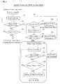
- Fig.2 is an example of flow chart of prevention process against erroneous detection of gear ratio step (without retention timer) in accordance with an embodiment of the present invention.
- a flow chart of upshift from 1st gear ratio step to 2nd gear ratio step is described.
- step S1 the determination apparatus of gear ratio step 6 firstly calculates an actual gear ratio of current gear ratio step.
- the actual gear ratio is obtained by calculating ratio of signal Nm corresponding to revolution of main shaft 3a sent from main revolution sensor 3d and signal Nc corresponding to revolution of counter shaft 3b sent from counter revolution sensor 3e. Note that the calculation result is stored as a gear ratio calculation Rg (as seen in Fig.3 ) in the determination apparatus of gear ratio step 6.
- step S2 the determination apparatus of gear ratio step 6 determines whether or not the gear ratio calculation Rg is within gear ratio variable allowance range of 1st gear ratio step.
- the "gear ratio variable allowance range” as used herein is defined as a range that is sandwiched by two dot-lines respectively disposed above or below from gear ratio of respective gear ratio steps in the gear ratio map as shown in Fig.6 .
- the "determination” as used herein means to determine whether or not a calculated gear ratio calculation Rg is within the gear ratio variable allowance range as shown in Fig.6 , and the result of the determination is stored as "gear ratio step calculation"(as seen in Fig.3 or Fig.5 ) in the determination apparatus of gear ratio step 6.
- step S1 if the gear ratio calculation Rg calculated in the step S1 is within the gear ratio variable allowance range of 1st gear ratio step (YES), the determination apparatus of gear ratio step goes to step S3. On the other hand, if the gear ratio calculation Rg deviates from the gear ratio variable allowance range of 1st gear ratio step (NO), the determination apparatus of gear ratio step 6 goes to step S6.
- step S3 the determination apparatus of gear ratio step 6 determines whether or not a current gear ratio step is neutral position.
- neutral position as used herein is defined as a position where any drive gears are not connected for rotation with input shaft 3a or output shaft 3b by synchronizers(so-called “disengaged position”).
- the neutral position is detected based on the neutral sensor signal Pn transmitted from the neutral sensor 5e. Therefore, if receiving an on-signal of the neutral sensor signal Pn, the determination apparatus of gear ratio step 6 determines a current gear ratio step as neutral position (YES) and goes to step S4 to redetermine whether or not a current gear ratio step is neutral position.
- the determination apparatus of gear ratio step 6 determines a current gear ratio step as not a neutral position (NO) and returns to step S1 to recalculate a gear ratio calculation Rg to be an actual gear ratio of current gear ratio step.
- step S4 the determination apparatus of gear ratio step 6 determines whether or not a current gear ratio step is neutral position. If determining a current gear ratio step as neutral position (YES), the determination apparatus of gear ratio step 6 makes a decision that a current gear ratio step is neutral position and goes to step S12 to make the status display of gear ratio step 7 to indicate nothing.
- the "decision" as used herein means that such a controller as determination apparatus of gear ratio step 6 has recognized a current gear ratio step as a status of gear ratio step (data) and a decided status of gear ratio is stored in the controller. Then, returning to the step S4, the determination apparatus of gear ratio step 6 performs the same process again. On the other hand, if determining a current gear ratio step as not a neutral position (NO), the determination apparatus of gear ratio step 6 goes to step S5 to calculate an actual gear ratio (gear ratio calculation Rg) of current gear ratio step.
- step S6 the determination apparatus of gear ratio step 6 determines whether or not the gear ratio calculation Rg is within gear ratio variable allowance range of 2nd gear ratio step to be next step. If the gear ratio calculation Rg calculated in the step S5 is within the gear ratio variable allowance range of 2nd gear ratio step (YES) as shown in Fig.6 , the determination apparatus of gear ratio step 6 goes to step S7 to make a delay timer get started. Note that delayed objective is a decision of current gear ratio step (current gear ratio position).
- current gear ratio step current gear ratio position
- gear ratio step gear ratio position
- the determination apparatus of gear ratio step 6 is supposed to make a decision that a status of current gear ratio step is in uncertainty, and therefore goes to step S13 to make the status display of gear ratio step 7 to indicate nothing. Then, the determination apparatus of gear ratio step 6 returns to the step S4 to perform the same process again.
- step S8 the determination apparatus of gear ratio step 6 calculates a gear ratio calculation Rg to be an actual gear ratio of current gear ratio step.
- step S9 the determination apparatus of gear ratio step 6 determines whether or not the gear ratio calculation Rg calculated in step S8 is within gear ratio variable allowance range of 2nd gear ratio step. If the gear ratio calculation Rg calculated in the step S8 is within the gear ratio variable allowance range of 2nd gear ratio step (YES), the determination apparatus of gear ratio step 6 goes to step S10. On the other hand, if the gear ratio calculation Rg deviates from the gear ratio variable allowance range of 2nd gear ratio step (NO), the determination apparatus of gear ratio step 6 cannot make a decision of a status of current gear ratio step, and therefore goes to step S14 to make the delay timer get stopped and delayed time reset to zero.
- the determination apparatus of gear ratio step 6 determines whether or not a current gear ratio step is neutral position. Note that the delay timer gets restarted from zero when the determination apparatus of gear ratio step 6 makes the delay timer get started in step S7 via steps S4 to S6, again.
- step S10 the determination apparatus of gear ratio step 6 determines whether or not delayed time (elapsed time after the delay timer gets started) exceeds a predetermined time T2*. If the determination apparatus of gear ratio step 6 determines that the delayed time exceeds the predetermined time T2*(YES), the determination apparatus of gear ratio step 6 makes a decision of status of current gear ratio step and goes to step S11 to make the status display of gear ratio step 7 to indicate "2" which means 2nd gear ratio step, thereby allows process of the above-mentioned flow chart to be terminated.
- the determination apparatus of gear ratio step 6 repeatedly performs calculation process of actual gear ratio in step S8 and determination process of current gear ratio step until the delayed time exceeds the predetermined time T2*, then going to step S11 to make the status display of gear ratio step 7 to indicate "2" which means 2nd gear ratio step, thereby allows process of the above-mentioned flow chart to be terminated as well.
- predetermined time T1* of 1st gear ratio step has maximum length among all determined time
- the predetermined time T2* of 2nd gear ratio step has larger length than the predetermined time T3* of 3rd gear ratio that has larger length than the predetermined time T4* of the 4th gear ratio step that has larger length than the predetermine time T5* of the 5th gear ratio step that has length of predetermined time T6* of 6th gear ratio step, as T1*> T2*> T3*> T4* >T5*> T6*. It is because transfer torque and gear moment are larger in gear ratio step with respect to low vehicle speed than in gear ratio step with respect to high vehicle speed.
- Fig.3 is an explanation drawing to show each of time charts regarding neutral sensor signal Pn, gear ratio calculation Rg of counter shaft revolution Nc and main shaft revolution Nm, and status of gear ratio step etc in association with the prevention process against erroneous detection of gear ratio step (without retention timer) as in Fig.2 .
- For reference is also shown each of time charts of shift load Ls, clutch stroke Sc, shift stroke Ss and engine revolution Ne.
- the "gear ratio step calculation" as used in Fig.3 is a index of status of current gear ratio step (1st, 2nd, ⁇ ) obtained by discrete processing of gear ratio calculation based on the gear ratio map.
- indication of status of gear ratio step changes from "1" to a blank meaning neutral position. From the time of t2 to the time of t4, the status of gear ratio step keeps on indicating the blank meaning neutral position.
- indication of gear ratio step calculation from the time of t3 to the time of t5 a current gear ratio step is determined as 1st gear ratio step (1st G.R.S.). That is, the indication of status of gear ratio step is different from the indication of gear ratio step calculation from the time of t3 to the time of t5.
- the determination apparatus of gear ratio step 6 determines status of current gear ratio step based on gear ratio calculation Rg (gear ratio step calculation). Especially, as the gear ratio step calculation is still unchangeably 1st gear ratio step during the time from t4 to t5, the determination apparatus of gear ratio step 6 determines current gear ratio step does not yet reach next gear ratio step (2nd gear ratio step in this case) and consequently makes a decision of current gear ratio step to be in uncertainty, consequently making nothing indicated in the status of gear ratio step. These determination and decision processes of uncertainty correspond to processes of steps where S5 goes to S6 to go to S13 to go likewise as in Fig.2 .
- gear ratio calculation Rg deviates from gear ratio variable allowance range of 1st gear ratio step(range sandwiched by two dotted lines in Fig.6 ).
- the determination apparatus of gear ratio step 6 also determines current gear ratio step does not yet reach 2nd gear ratio step and consequently makes a decision of current gear ratio step to be in uncertainty, consequently making nothing indicated in the status of gear ratio step.
- These determination and decision processes of uncertainty also correspond to processes of steps where S4 goes to S5 to go to S6 to go to S13 to go likewise as in Fig.2 .
- gear ratio calculation Rg goes within gear ratio variable allowance range of 2nd gear ratio step and then, the determination apparatus of gear ratio step 6 makes a delay timer get started and begins to measure a delayed time. But, at the time of t7, as gear ratio step calculation deviates from the gear ratio variable allowance range of 2nd gear ratio step, the delay timer is made get stopped and delayed time reset at the same time. Therefore, from the time of t6 to the time of t7, the determination apparatus of gear ratio step 6 determines current gear ratio step does not yet reach 2nd gear ratio step and consequently makes a decision of current gear ratio step to be in uncertainty, making nothing indicated in the status of gear ratio step.
- gear ratio calculation Rg again goes within gear ratio variable allowance range of 2nd gear ratio step and then, the determination apparatus of gear ratio step 6 again makes delay timer get started and begins to measure a delayed time.
- the delay timer gets terminated and then, the determination apparatus of gear ratio step 6 makes a decision of status of current gear ratio step with referring to result of the gear ratio step calculation, making the status of gear ratio step to indicate "2" meaning 2nd gear ratio step.
- the determination apparatus of gear ratio step 6 when making a decision of current gear ratio step(gear ratio step of currently engaged gear) determined on the basis of gear ratio calculation Rg and gear ratio map, the determination apparatus of gear ratio step 6 is, by the delay timer to halt making a decision of current gear ratio step for a predetermined time, configured to halt to make the decision of current gear ratio step during activation or at completion time of the synchronizer when each of revolutions of the input and output shafts unsteadily fluctuates.
- the determination apparatus of gear ratio step 6 is prevented from erroneous detection of current gear ratio step.
- a calculation of actual gear ratio (gear ratio calculation Rg) as used in determining current gear ratio step is conducted based on each of revolutions Nm,Nc of main shaft 3a and counter shaft 3b, and consequently it becomes to be possible to accurately determine the current gear ratio step regardless of clutch engagement.
- the prevention process against erroneous detection of gear ratio step includes a retention timer to keep on indicating status of gear ratio step immediately before change of gear ratio step for a predetermined time.
- Fig.4 is an example of flow chart of prevention process against erroneous detection of gear ratio step (with retention timer) in accordance with another embodiment of the present invention. Note that hereinafter is described a flow chart of jumping downshift from 3rd gear ratio step to 1st gear ratio step.
- step S1 the determination apparatus of gear ratio step 6 firstly calculates an actual gear ratio of current gear ratio step.
- the actual gear ratio is obtained by calculating ratio of signals Nm,Nc corresponding to revolutions of main and counter shafts 3a,3b sent from main and counter revolution sensors 3d,3e, respectively. Note that the calculation result is stored as a gear ratio calculation Rg ( Fig.5 ) in the determination apparatus of gear ratio step 6.
- step S2 the determination apparatus of gear ratio step 6 determines whether or not the gear ratio calculation Rg is within gear ratio variable allowance range of 3rd gear ratio step. In this case, if the gear ratio calculation Rg calculated in the step S1 is within the gear ratio variable allowance range of 3rd gear ratio step (YES), the determination apparatus of gear ratio step goes to step S3. On the other hand, if the gear ratio calculation Rg deviates from the gear ratio variable allowance range of 3rd gear ratio step (NO), the determination apparatus of gear ratio step 6 goes to step S4 to make the retention timer get started.
- step S3 the determination apparatus of gear ratio step 6 determines whether or not a current gear ratio step is neutral position. In this case, if receiving on-signal of neutral sensor signal Pn, the determination apparatus of gear ratio step 6 determines a current gear ratio step as a neutral position (YES) and goes to step S4 to make the retention timer get started. On the other hand, if not receiving on-signal of neutral sensor signal Pn, the determination apparatus of gear ratio step 6 determines a current gear ratio step as not a neutral position (NO) and returns to step S1 to recalculate a gear ratio calculation Rg to be an actual gear ratio of current gear ratio step.
- the determination apparatus of gear ratio step 6 makes the retention timer get started at the time which is earlier when gear ratio calculation Rg deviates from gear ratio variable allowance range corresponding to current gear ratio step or when the determination apparatus of gear ratio step 6 receives on-signal of neutral sensor signal Pn.
- step S4 the determination apparatus of gear ratio step 6 makes the retention timer get started(begins to measure a retention time). During activation of the retention timer, the determination apparatus of gear ratio step 6 makes indicate a status of gear ratio step immediately before the retention timer gets started. Note that the determination apparatus of gear ratio step 6 may make indicate nothing instead of indicating a status of gear ratio step immediately before the retention timer gets started.
- step S5 the determination apparatus of gear ratio step 6 calculates a gear ratio calculation Rg to be an actual gear ratio of current gear ratio step.
- step S6 the determination apparatus of gear ratio step 6 determines whether or not the gear ratio calculation Rg is within gear ratio variable allowance range of 2nd gear ratio step to be next step. If the gear ratio calculation Rg is, as in step S2, within the gear ratio variable allowance range of 2nd gear ratio step (YES) as shown in Fig.6 , the determination apparatus of gear ratio step 6 goes to step S11 to make a delay timer get started. On the other hand, if the gear ratio calculation Rg deviates within the gear ratio variable allowance range of 2nd gear ratio step (NO) as shown in Fig.6 , the determination apparatus of gear ratio step 6 goes to step S7.
- the determination apparatus of gear ratio step 6 makes the retention timer get stopped and the delay timer get started. That is, the delay timer is processed with priority over retention timer in the prevention process against erroneous detection of gear ratio step in accordance with the present invention.
- step S7 the determination apparatus of gear ratio step 6 determines whether or not the retention time (elapsed time after the retention timer gets started) exceeds a predetermined time T k . If the determination apparatus of gear ratio step 6 determines that the retention time exceeds the predetermined time T k (YES), the determination apparatus of gear ratio step 6 goes to step S8. On the other hand, if determining that the retention time does not exceed the predetermined time T k (NO), the determination apparatus of gear ratio step 6 returns to step S5 to calculate a gear ratio calculation Rg to be a actual gear ratio of current gear ratio step.
- step S8 the determination apparatus of gear ratio step 6 determines whether or not a current gear ratio step is neutral position. If determining that a current gear ratio step is neutral position (YES), the determination apparatus of gear ratio step 6 makes a decision of a status of current gear ratio step as neutral position and goes to step S16 to make status display of gear ratio step 7 to indicate nothing, returning to step S8 and perform the same process again. On the other hand, if determining a current gear ratio step as not a neutral position (NO) and goes to step S9 to recalculate a gear ratio calculation Rg to be an actual gear ratio of current gear ratio step as well as in steps S1 and S5.
- step S10 the determination apparatus of gear ratio step 6 determines whether or not a gear ratio calculation Rg is within gear ratio variable allowance range of the 1st gear ratio step to be next step. If the gear ratio calculation Rg calculated in step S9 is within the gear ratio variable allowance range of 1st gear ratio step (YES), the determination apparatus of gear ratio step 6 goes to step S11 to make a delay timer get started.
- the determination apparatus of gear ratio step 6 determines a current gear ratio step does not yet reach 1st gear ratio step and consequently makes a decision of the current gear ratio step to be in uncertainty, going to step S17 and making status display of gear ratio step 7 to indicate nothing. Then, the determination apparatus of gear ratio step 6 returns to step S8 and performs the same process again.
- step S12 the determination apparatus of gear ratio step 6 calculates a gear ratio calculation Rg to be an actual gear ratio of current gear ratio step.
- step S13 the determination apparatus of gear ratio step 6 determines whether or not a gear ratio calculation Rg is within gear ratio variable allowance range of the 1st gear ratio step to be next step. If gear ratio calculation Rg calculated in step S12 is within gear ratio variable allowance range of the 1st gear ratio step (YES) as shown in Fig.6 , the determination apparatus of gear ratio step 6 goes to step S14. On the other hand, if the gear ratio calculation Rg deviates from gear ratio variable allowance range of the 1st gear ratio as shown in Fig.6 (NO), the determination apparatus of gear ratio step 6, as status of gear ratio step is not yet decided, goes to step S18 to make the delay timer get stopped and reset to zero with respect to time-length.
- the determination apparatus of gear ratio step 6 returns to step S8 again to determine whether or not current gear ratio step is neutral position. Note that the determination apparatus of gear ratio step 6 makes the delay timer restart from zero when making the delay timer get started in step S10 that follows after steps S8 and S9, in turn.
- step S14 the determination apparatus of gear ratio step 6 determines whether or not the delayed time (elapsed time after the delay timer get started) exceeds a predetermined time T1*. If the determination apparatus of gear ratio step 6 determines that the delayed time exceeds the predetermined time T1*(YES), the determination apparatus of gear ratio step 6 determines that current gear ratio step has reached the 1st gear ratio, and then goes to S15 to make the status display of gear ratio step 7 to indicate "1" meaning 1st gear ratio step, afterward terminating the process.
- the determination apparatus of gear ratio step 6 repeatedly performs calculation process of actual gear ratio (in step S12) and determination process of current gear ratio (in step S13) step until the delayed time exceeds the predetermined time T1*, then going to step S15 to make the status display of gear ratio step 7 to indicate "1" which means 1st gear ratio step, afterward terminating the process as well.
- Fig.5 is an explanation drawing to show each of time charts regarding neutral sensor signal Pn, gear ratio calculation Rg of counter shaft revolution Nc and main shaft revolution Nm, and status of gear ratio step etc in association with the prevention process against erroneous detection of gear ratio step (with retention timer) as in Fig.4 .
- For reference is also shown each of time charts of shift load Ls, clutch stroke Sc, shift stroke Ss and engine revolution Ne.
- the "gear ratio step calculation" as used in Fig.5 is a index of status of current gear ratio step (1st, 2nd, ⁇ ) obtained by discrete processing of gear ratio calculation Rg based on the gear ratio map.
- the determination apparatus of gear ratio step 6 respectively performs gear ratio calculation Rg and gear ratio step calculation, with taking in signals of counter shaft revolution Nc and main shaft revolution Nm. These processes correspond to, for example, steps S1 and S2 of Fig.4 .
- the determination apparatus of gear ratio step 6 makes a retention timer get started(begins to measure a retention time). During activation of the retention timer, the determination apparatus of gear ratio step 6 makes the status display of gear ratio step 7 to indicate a status of gear ratio step immediately before receiving the ON level of neutral sensor signal Pn. In this case, the status of gear ratio step immediately before receiving the ON level is 3rd gear ratio step and the determination apparatus of gear ratio step 6 makes the status display of gear ratio step 7 to indicate "3" meaning 3rd gear ratio step (3rd G.R.S.).
- gear ratio calculation Rg (actual gear ratio) deviates from gear ratio variable allowance range of 2nd gear ratio step and the determination apparatus of gear ratio 6 step makes the delay timer get stopped and delayed time reset to zero. In the result, the delayed get stopped in the middle of predetermined time T2*.
- the determination apparatus of gear ratio step 6 cannot make a decision of status of gear ratio step and consequently makes the status display of gear ratio step 7 to indicate nothing without indicating "2" meaning 2nd gear ratio step.
- gear ratio calculation Rg goes within gear ratio variable allowance range of 1st gear ratio step and then, the determination apparatus of gear ratio step 6 makes the delay timer get started and begins to measure a delayed time.
- the determination apparatus of gear ratio step 6 makes a decision of status of current gear ratio step with referring to result of the gear ratio step calculation, making the status of gear ratio step to indicate "1" meaning 1st gear ratio step (1st G.R.S.).
- the determination apparatus of gear ratio step 6 when making a decision of current gear ratio step(gear ratio step of currently engaged gear) determined on the basis of gear ratio calculation Rg and gear ratio map, the determination apparatus of gear ratio step 6 is, by the delay timer to halt making a decision of current gear ratio step for a predetermined time, configured to halt to make the decision of current gear ratio step during activation or at completion time of the synchronizer when each of revolutions of the input and output shafts unsteadily fluctuates.
- the determination apparatus of gear ratio step 6 is prevented from erroneous detection of current gear ratio step.
- a calculation of actual gear ratio (gear ratio calculation Rg) as used in determining current gear ratio step is conducted based on each of revolutions Nm,Nc of main shaft 3a and counter shaft 3b, and consequently it becomes to be possible to accurately determine the current gear ratio step regardless of clutch engagement.
- a retention timer to keep on indicating a status of gear ratio immediately before change of gear ratio step, makes blank indication to be shorten in status of gear ratio step and consequently it becomes to be possible to more preferably prevent on-off intermittent indication of the current gear ratio step and temporary indication of the intermediate gear ratio steps in merely passing. In the result, a driver comes to feel nothing unnatural with respect to gear ratio change.
Landscapes
- Engineering & Computer Science (AREA)
- General Engineering & Computer Science (AREA)
- Mechanical Engineering (AREA)
- Control Of Transmission Device (AREA)
Applications Claiming Priority (1)
| Application Number | Priority Date | Filing Date | Title |
|---|---|---|---|
| JP2014114415A JP6310777B2 (ja) | 2014-06-02 | 2014-06-02 | 変速機 |
Publications (2)
| Publication Number | Publication Date |
|---|---|
| EP2952782A1 true EP2952782A1 (de) | 2015-12-09 |
| EP2952782B1 EP2952782B1 (de) | 2019-10-02 |
Family
ID=53365771
Family Applications (1)
| Application Number | Title | Priority Date | Filing Date |
|---|---|---|---|
| EP15169407.2A Active EP2952782B1 (de) | 2014-06-02 | 2015-05-27 | Getriebe |
Country Status (3)
| Country | Link |
|---|---|
| US (1) | US9951863B2 (de) |
| EP (1) | EP2952782B1 (de) |
| JP (1) | JP6310777B2 (de) |
Families Citing this family (3)
| Publication number | Priority date | Publication date | Assignee | Title |
|---|---|---|---|---|
| JP7170003B2 (ja) * | 2020-01-17 | 2022-11-11 | 日立Astemo株式会社 | ギヤポジション故障検知装置 |
| JP7687286B2 (ja) * | 2022-06-29 | 2025-06-03 | トヨタ自動車株式会社 | 車両の制御装置 |
| CN115182995B (zh) * | 2022-06-30 | 2024-06-04 | 东风商用车有限公司 | 一种手动变速箱档位判断方法及系统 |
Citations (5)
| Publication number | Priority date | Publication date | Assignee | Title |
|---|---|---|---|---|
| DE19908831A1 (de) * | 1999-03-01 | 2000-09-07 | Volkswagen Ag | Verfahren und Vorrichtung zur Gangerkennung bei einem Kraftfahrzeug |
| EP1271005A2 (de) * | 2001-06-18 | 2003-01-02 | Siemens VDO Automotive S.A.S. | Verfahren und Vorrichtung zur Erkennung der Schaltposition eines Schaltgetriebes |
| DE102004001880A1 (de) * | 2004-01-14 | 2005-08-11 | Robert Bosch Gmbh | Verfahren und Vorrichtung zur Gangerkennung bei einem Kraftfahrzeug |
| JP2008039111A (ja) | 2006-08-08 | 2008-02-21 | Toyota Motor Corp | 変速指示装置 |
| JP4404096B2 (ja) | 2007-01-10 | 2010-01-27 | トヨタ自動車株式会社 | ギヤ位置判定装置及び変速指示装置 |
Family Cites Families (4)
| Publication number | Priority date | Publication date | Assignee | Title |
|---|---|---|---|---|
| JP2585697Y2 (ja) * | 1989-06-20 | 1998-11-25 | 三菱自動車工業株式会社 | 変速段表示装置 |
| JP3433934B2 (ja) * | 2001-11-27 | 2003-08-04 | 富士重工業株式会社 | 自動変速装置 |
| JP2010184535A (ja) * | 2009-02-10 | 2010-08-26 | Toyota Motor Corp | ハイブリッド車両 |
| JP2013194868A (ja) * | 2012-03-21 | 2013-09-30 | Honda Motor Co Ltd | 変速機の制御装置 |
-
2014
- 2014-06-02 JP JP2014114415A patent/JP6310777B2/ja active Active
-
2015
- 2015-05-07 US US14/706,145 patent/US9951863B2/en active Active
- 2015-05-27 EP EP15169407.2A patent/EP2952782B1/de active Active
Patent Citations (5)
| Publication number | Priority date | Publication date | Assignee | Title |
|---|---|---|---|---|
| DE19908831A1 (de) * | 1999-03-01 | 2000-09-07 | Volkswagen Ag | Verfahren und Vorrichtung zur Gangerkennung bei einem Kraftfahrzeug |
| EP1271005A2 (de) * | 2001-06-18 | 2003-01-02 | Siemens VDO Automotive S.A.S. | Verfahren und Vorrichtung zur Erkennung der Schaltposition eines Schaltgetriebes |
| DE102004001880A1 (de) * | 2004-01-14 | 2005-08-11 | Robert Bosch Gmbh | Verfahren und Vorrichtung zur Gangerkennung bei einem Kraftfahrzeug |
| JP2008039111A (ja) | 2006-08-08 | 2008-02-21 | Toyota Motor Corp | 変速指示装置 |
| JP4404096B2 (ja) | 2007-01-10 | 2010-01-27 | トヨタ自動車株式会社 | ギヤ位置判定装置及び変速指示装置 |
Also Published As
| Publication number | Publication date |
|---|---|
| US20150345618A1 (en) | 2015-12-03 |
| JP2015227713A (ja) | 2015-12-17 |
| JP6310777B2 (ja) | 2018-04-11 |
| EP2952782B1 (de) | 2019-10-02 |
| US9951863B2 (en) | 2018-04-24 |
Similar Documents
| Publication | Publication Date | Title |
|---|---|---|
| JP5058068B2 (ja) | 変速機構の制御装置、制御方法及び原動機付き車両の制御方法 | |
| CA2644741A1 (en) | System and method for matching engine speed to vehicle speed with a manual transmission | |
| WO2004097266A1 (en) | Drive transmission | |
| CN109099154B (zh) | 一种双离合变速器的挡位控制方法及装置 | |
| EP2952782B1 (de) | Getriebe | |
| EP2653753A1 (de) | Steuerungsvorrichtung für ein doppelkupplungsgetriebe und steuerverfahren für ein doppelkupplungsgetriebe | |
| US20100024581A1 (en) | Dual clutch transmission | |
| KR102030144B1 (ko) | Dct 차량의 변속제어방법 | |
| JP5131126B2 (ja) | ツインクラッチ式変速機の制御装置 | |
| CN108025643B (zh) | 转速显示装置 | |
| JP2002071005A (ja) | 同期噛合式変速機における変速制御装置 | |
| CN103765053B (zh) | 双离合器式自动变速器 | |
| CN111963678B (zh) | 一种拨叉同步点的确定方法和装置 | |
| EP2781798A1 (de) | Automatikgetriebe und verfahren zur bestimmung eines auswahlbetriebs des automatikgetriebes | |
| CN104806747B (zh) | 离合器压力控制装置 | |
| JP6730945B2 (ja) | 電子制御装置 | |
| US8768588B2 (en) | Transmission and method of shift control for transmission | |
| JP2016070444A (ja) | デュアルクラッチ式変速機の制御装置 | |
| JP2014227965A (ja) | 内燃機関の制御装置 | |
| CN110230695B (zh) | 一种双离合器动力冲突故障确定的方法和装置 | |
| JP2004245358A (ja) | ニュートラルスイッチの異常判定装置 | |
| CN112041595B (zh) | 用于学习车辆手动变速器空挡和挡位的方法 | |
| EP2832604A1 (de) | Antriebsvorrichtung für ein Fahrzeug | |
| EP3059475A1 (de) | Steuerungsvorrichtung für ein fahrzeug | |
| JP2009191868A (ja) | 車両の制御装置および制御方法 |
Legal Events
| Date | Code | Title | Description |
|---|---|---|---|
| PUAI | Public reference made under article 153(3) epc to a published international application that has entered the european phase |
Free format text: ORIGINAL CODE: 0009012 |
|
| 17P | Request for examination filed |
Effective date: 20150527 |
|
| AK | Designated contracting states |
Kind code of ref document: A1 Designated state(s): AL AT BE BG CH CY CZ DE DK EE ES FI FR GB GR HR HU IE IS IT LI LT LU LV MC MK MT NL NO PL PT RO RS SE SI SK SM TR |
|
| AX | Request for extension of the european patent |
Extension state: BA ME |
|
| GRAP | Despatch of communication of intention to grant a patent |
Free format text: ORIGINAL CODE: EPIDOSNIGR1 |
|
| STAA | Information on the status of an ep patent application or granted ep patent |
Free format text: STATUS: GRANT OF PATENT IS INTENDED |
|
| INTG | Intention to grant announced |
Effective date: 20190605 |
|
| GRAS | Grant fee paid |
Free format text: ORIGINAL CODE: EPIDOSNIGR3 |
|
| GRAA | (expected) grant |
Free format text: ORIGINAL CODE: 0009210 |
|
| STAA | Information on the status of an ep patent application or granted ep patent |
Free format text: STATUS: THE PATENT HAS BEEN GRANTED |
|
| AK | Designated contracting states |
Kind code of ref document: B1 Designated state(s): AL AT BE BG CH CY CZ DE DK EE ES FI FR GB GR HR HU IE IS IT LI LT LU LV MC MK MT NL NO PL PT RO RS SE SI SK SM TR |
|
| REG | Reference to a national code |
Ref country code: GB Ref legal event code: FG4D |
|
| REG | Reference to a national code |
Ref country code: AT Ref legal event code: REF Ref document number: 1186542 Country of ref document: AT Kind code of ref document: T Effective date: 20191015 Ref country code: CH Ref legal event code: EP |
|
| REG | Reference to a national code |
Ref country code: DE Ref legal event code: R096 Ref document number: 602015038937 Country of ref document: DE |
|
| REG | Reference to a national code |
Ref country code: IE Ref legal event code: FG4D |
|
| REG | Reference to a national code |
Ref country code: NL Ref legal event code: MP Effective date: 20191002 |
|
| REG | Reference to a national code |
Ref country code: LT Ref legal event code: MG4D |
|
| REG | Reference to a national code |
Ref country code: AT Ref legal event code: MK05 Ref document number: 1186542 Country of ref document: AT Kind code of ref document: T Effective date: 20191002 |
|
| PG25 | Lapsed in a contracting state [announced via postgrant information from national office to epo] |
Ref country code: FI Free format text: LAPSE BECAUSE OF FAILURE TO SUBMIT A TRANSLATION OF THE DESCRIPTION OR TO PAY THE FEE WITHIN THE PRESCRIBED TIME-LIMIT Effective date: 20191002 Ref country code: AT Free format text: LAPSE BECAUSE OF FAILURE TO SUBMIT A TRANSLATION OF THE DESCRIPTION OR TO PAY THE FEE WITHIN THE PRESCRIBED TIME-LIMIT Effective date: 20191002 Ref country code: PT Free format text: LAPSE BECAUSE OF FAILURE TO SUBMIT A TRANSLATION OF THE DESCRIPTION OR TO PAY THE FEE WITHIN THE PRESCRIBED TIME-LIMIT Effective date: 20200203 Ref country code: GR Free format text: LAPSE BECAUSE OF FAILURE TO SUBMIT A TRANSLATION OF THE DESCRIPTION OR TO PAY THE FEE WITHIN THE PRESCRIBED TIME-LIMIT Effective date: 20200103 Ref country code: ES Free format text: LAPSE BECAUSE OF FAILURE TO SUBMIT A TRANSLATION OF THE DESCRIPTION OR TO PAY THE FEE WITHIN THE PRESCRIBED TIME-LIMIT Effective date: 20191002 Ref country code: LV Free format text: LAPSE BECAUSE OF FAILURE TO SUBMIT A TRANSLATION OF THE DESCRIPTION OR TO PAY THE FEE WITHIN THE PRESCRIBED TIME-LIMIT Effective date: 20191002 Ref country code: SE Free format text: LAPSE BECAUSE OF FAILURE TO SUBMIT A TRANSLATION OF THE DESCRIPTION OR TO PAY THE FEE WITHIN THE PRESCRIBED TIME-LIMIT Effective date: 20191002 Ref country code: NL Free format text: LAPSE BECAUSE OF FAILURE TO SUBMIT A TRANSLATION OF THE DESCRIPTION OR TO PAY THE FEE WITHIN THE PRESCRIBED TIME-LIMIT Effective date: 20191002 Ref country code: BG Free format text: LAPSE BECAUSE OF FAILURE TO SUBMIT A TRANSLATION OF THE DESCRIPTION OR TO PAY THE FEE WITHIN THE PRESCRIBED TIME-LIMIT Effective date: 20200102 Ref country code: LT Free format text: LAPSE BECAUSE OF FAILURE TO SUBMIT A TRANSLATION OF THE DESCRIPTION OR TO PAY THE FEE WITHIN THE PRESCRIBED TIME-LIMIT Effective date: 20191002 Ref country code: NO Free format text: LAPSE BECAUSE OF FAILURE TO SUBMIT A TRANSLATION OF THE DESCRIPTION OR TO PAY THE FEE WITHIN THE PRESCRIBED TIME-LIMIT Effective date: 20200102 Ref country code: PL Free format text: LAPSE BECAUSE OF FAILURE TO SUBMIT A TRANSLATION OF THE DESCRIPTION OR TO PAY THE FEE WITHIN THE PRESCRIBED TIME-LIMIT Effective date: 20191002 |
|
| PG25 | Lapsed in a contracting state [announced via postgrant information from national office to epo] |
Ref country code: HR Free format text: LAPSE BECAUSE OF FAILURE TO SUBMIT A TRANSLATION OF THE DESCRIPTION OR TO PAY THE FEE WITHIN THE PRESCRIBED TIME-LIMIT Effective date: 20191002 Ref country code: CZ Free format text: LAPSE BECAUSE OF FAILURE TO SUBMIT A TRANSLATION OF THE DESCRIPTION OR TO PAY THE FEE WITHIN THE PRESCRIBED TIME-LIMIT Effective date: 20191002 Ref country code: RS Free format text: LAPSE BECAUSE OF FAILURE TO SUBMIT A TRANSLATION OF THE DESCRIPTION OR TO PAY THE FEE WITHIN THE PRESCRIBED TIME-LIMIT Effective date: 20191002 Ref country code: IS Free format text: LAPSE BECAUSE OF FAILURE TO SUBMIT A TRANSLATION OF THE DESCRIPTION OR TO PAY THE FEE WITHIN THE PRESCRIBED TIME-LIMIT Effective date: 20200224 |
|
| PG25 | Lapsed in a contracting state [announced via postgrant information from national office to epo] |
Ref country code: AL Free format text: LAPSE BECAUSE OF FAILURE TO SUBMIT A TRANSLATION OF THE DESCRIPTION OR TO PAY THE FEE WITHIN THE PRESCRIBED TIME-LIMIT Effective date: 20191002 |
|
| REG | Reference to a national code |
Ref country code: DE Ref legal event code: R097 Ref document number: 602015038937 Country of ref document: DE |
|
| PG2D | Information on lapse in contracting state deleted |
Ref country code: IS |
|
| PG25 | Lapsed in a contracting state [announced via postgrant information from national office to epo] |
Ref country code: IS Free format text: LAPSE BECAUSE OF FAILURE TO SUBMIT A TRANSLATION OF THE DESCRIPTION OR TO PAY THE FEE WITHIN THE PRESCRIBED TIME-LIMIT Effective date: 20200202 Ref country code: RO Free format text: LAPSE BECAUSE OF FAILURE TO SUBMIT A TRANSLATION OF THE DESCRIPTION OR TO PAY THE FEE WITHIN THE PRESCRIBED TIME-LIMIT Effective date: 20191002 Ref country code: EE Free format text: LAPSE BECAUSE OF FAILURE TO SUBMIT A TRANSLATION OF THE DESCRIPTION OR TO PAY THE FEE WITHIN THE PRESCRIBED TIME-LIMIT Effective date: 20191002 Ref country code: DK Free format text: LAPSE BECAUSE OF FAILURE TO SUBMIT A TRANSLATION OF THE DESCRIPTION OR TO PAY THE FEE WITHIN THE PRESCRIBED TIME-LIMIT Effective date: 20191002 |
|
| PLBE | No opposition filed within time limit |
Free format text: ORIGINAL CODE: 0009261 |
|
| STAA | Information on the status of an ep patent application or granted ep patent |
Free format text: STATUS: NO OPPOSITION FILED WITHIN TIME LIMIT |
|
| PG25 | Lapsed in a contracting state [announced via postgrant information from national office to epo] |
Ref country code: SM Free format text: LAPSE BECAUSE OF FAILURE TO SUBMIT A TRANSLATION OF THE DESCRIPTION OR TO PAY THE FEE WITHIN THE PRESCRIBED TIME-LIMIT Effective date: 20191002 Ref country code: IT Free format text: LAPSE BECAUSE OF FAILURE TO SUBMIT A TRANSLATION OF THE DESCRIPTION OR TO PAY THE FEE WITHIN THE PRESCRIBED TIME-LIMIT Effective date: 20191002 Ref country code: SK Free format text: LAPSE BECAUSE OF FAILURE TO SUBMIT A TRANSLATION OF THE DESCRIPTION OR TO PAY THE FEE WITHIN THE PRESCRIBED TIME-LIMIT Effective date: 20191002 |
|
| 26N | No opposition filed |
Effective date: 20200703 |
|
| PG25 | Lapsed in a contracting state [announced via postgrant information from national office to epo] |
Ref country code: SI Free format text: LAPSE BECAUSE OF FAILURE TO SUBMIT A TRANSLATION OF THE DESCRIPTION OR TO PAY THE FEE WITHIN THE PRESCRIBED TIME-LIMIT Effective date: 20191002 |
|
| PG25 | Lapsed in a contracting state [announced via postgrant information from national office to epo] |
Ref country code: LI Free format text: LAPSE BECAUSE OF NON-PAYMENT OF DUE FEES Effective date: 20200531 Ref country code: MC Free format text: LAPSE BECAUSE OF FAILURE TO SUBMIT A TRANSLATION OF THE DESCRIPTION OR TO PAY THE FEE WITHIN THE PRESCRIBED TIME-LIMIT Effective date: 20191002 Ref country code: CH Free format text: LAPSE BECAUSE OF NON-PAYMENT OF DUE FEES Effective date: 20200531 |
|
| REG | Reference to a national code |
Ref country code: BE Ref legal event code: MM Effective date: 20200531 |
|
| PG25 | Lapsed in a contracting state [announced via postgrant information from national office to epo] |
Ref country code: LU Free format text: LAPSE BECAUSE OF NON-PAYMENT OF DUE FEES Effective date: 20200527 |
|
| PG25 | Lapsed in a contracting state [announced via postgrant information from national office to epo] |
Ref country code: IE Free format text: LAPSE BECAUSE OF NON-PAYMENT OF DUE FEES Effective date: 20200527 Ref country code: FR Free format text: LAPSE BECAUSE OF NON-PAYMENT OF DUE FEES Effective date: 20200531 |
|
| PG25 | Lapsed in a contracting state [announced via postgrant information from national office to epo] |
Ref country code: BE Free format text: LAPSE BECAUSE OF NON-PAYMENT OF DUE FEES Effective date: 20200531 |
|
| REG | Reference to a national code |
Ref country code: DE Ref legal event code: R084 Ref document number: 602015038937 Country of ref document: DE |
|
| REG | Reference to a national code |
Ref country code: GB Ref legal event code: 746 Effective date: 20210901 |
|
| PG25 | Lapsed in a contracting state [announced via postgrant information from national office to epo] |
Ref country code: TR Free format text: LAPSE BECAUSE OF FAILURE TO SUBMIT A TRANSLATION OF THE DESCRIPTION OR TO PAY THE FEE WITHIN THE PRESCRIBED TIME-LIMIT Effective date: 20191002 Ref country code: MT Free format text: LAPSE BECAUSE OF FAILURE TO SUBMIT A TRANSLATION OF THE DESCRIPTION OR TO PAY THE FEE WITHIN THE PRESCRIBED TIME-LIMIT Effective date: 20191002 Ref country code: CY Free format text: LAPSE BECAUSE OF FAILURE TO SUBMIT A TRANSLATION OF THE DESCRIPTION OR TO PAY THE FEE WITHIN THE PRESCRIBED TIME-LIMIT Effective date: 20191002 |
|
| PG25 | Lapsed in a contracting state [announced via postgrant information from national office to epo] |
Ref country code: MK Free format text: LAPSE BECAUSE OF FAILURE TO SUBMIT A TRANSLATION OF THE DESCRIPTION OR TO PAY THE FEE WITHIN THE PRESCRIBED TIME-LIMIT Effective date: 20191002 |
|
| PGFP | Annual fee paid to national office [announced via postgrant information from national office to epo] |
Ref country code: DE Payment date: 20250423 Year of fee payment: 11 |
|
| PGFP | Annual fee paid to national office [announced via postgrant information from national office to epo] |
Ref country code: GB Payment date: 20250423 Year of fee payment: 11 |