EP2952797A1 - Anschlussverbindung für rohrleitungen zur förderung von gas, druckluft und anderen flüssigkeiten - Google Patents
Anschlussverbindung für rohrleitungen zur förderung von gas, druckluft und anderen flüssigkeiten Download PDFInfo
- Publication number
- EP2952797A1 EP2952797A1 EP15170425.1A EP15170425A EP2952797A1 EP 2952797 A1 EP2952797 A1 EP 2952797A1 EP 15170425 A EP15170425 A EP 15170425A EP 2952797 A1 EP2952797 A1 EP 2952797A1
- Authority
- EP
- European Patent Office
- Prior art keywords
- tubular element
- ring
- joint
- flange
- internal ring
- Prior art date
- Legal status (The legal status is an assumption and is not a legal conclusion. Google has not performed a legal analysis and makes no representation as to the accuracy of the status listed.)
- Granted
Links
Images


Classifications
-
- F—MECHANICAL ENGINEERING; LIGHTING; HEATING; WEAPONS; BLASTING
- F16—ENGINEERING ELEMENTS AND UNITS; GENERAL MEASURES FOR PRODUCING AND MAINTAINING EFFECTIVE FUNCTIONING OF MACHINES OR INSTALLATIONS; THERMAL INSULATION IN GENERAL
- F16L—PIPES; JOINTS OR FITTINGS FOR PIPES; SUPPORTS FOR PIPES, CABLES OR PROTECTIVE TUBING; MEANS FOR THERMAL INSULATION IN GENERAL
- F16L19/00—Joints in which sealing surfaces are pressed together by means of a member, e.g. a swivel nut, screwed on, or into, one of the joint parts
- F16L19/02—Pipe ends provided with collars or flanges, integral with the pipe or not, pressed together by a screwed member
- F16L19/0206—Pipe ends provided with collars or flanges, integral with the pipe or not, pressed together by a screwed member the collar not being integral with the pipe
-
- F—MECHANICAL ENGINEERING; LIGHTING; HEATING; WEAPONS; BLASTING
- F16—ENGINEERING ELEMENTS AND UNITS; GENERAL MEASURES FOR PRODUCING AND MAINTAINING EFFECTIVE FUNCTIONING OF MACHINES OR INSTALLATIONS; THERMAL INSULATION IN GENERAL
- F16L—PIPES; JOINTS OR FITTINGS FOR PIPES; SUPPORTS FOR PIPES, CABLES OR PROTECTIVE TUBING; MEANS FOR THERMAL INSULATION IN GENERAL
- F16L19/00—Joints in which sealing surfaces are pressed together by means of a member, e.g. a swivel nut, screwed on, or into, one of the joint parts
- F16L19/04—Joints in which sealing surfaces are pressed together by means of a member, e.g. a swivel nut, screwed on, or into, one of the joint parts using additional rigid rings, sealing directly on at least one pipe end, which is flared either before or during the making of the connection
- F16L19/043—Joints in which sealing surfaces are pressed together by means of a member, e.g. a swivel nut, screwed on, or into, one of the joint parts using additional rigid rings, sealing directly on at least one pipe end, which is flared either before or during the making of the connection with additional sealing means
- F16L19/046—Joints in which sealing surfaces are pressed together by means of a member, e.g. a swivel nut, screwed on, or into, one of the joint parts using additional rigid rings, sealing directly on at least one pipe end, which is flared either before or during the making of the connection with additional sealing means consisting of a soft ring
-
- F—MECHANICAL ENGINEERING; LIGHTING; HEATING; WEAPONS; BLASTING
- F16—ENGINEERING ELEMENTS AND UNITS; GENERAL MEASURES FOR PRODUCING AND MAINTAINING EFFECTIVE FUNCTIONING OF MACHINES OR INSTALLATIONS; THERMAL INSULATION IN GENERAL
- F16L—PIPES; JOINTS OR FITTINGS FOR PIPES; SUPPORTS FOR PIPES, CABLES OR PROTECTIVE TUBING; MEANS FOR THERMAL INSULATION IN GENERAL
- F16L19/00—Joints in which sealing surfaces are pressed together by means of a member, e.g. a swivel nut, screwed on, or into, one of the joint parts
- F16L19/02—Pipe ends provided with collars or flanges, integral with the pipe or not, pressed together by a screwed member
- F16L19/0212—Pipe ends provided with collars or flanges, integral with the pipe or not, pressed together by a screwed member using specially adapted sealing means
- F16L19/0218—Pipe ends provided with collars or flanges, integral with the pipe or not, pressed together by a screwed member using specially adapted sealing means comprising only sealing rings
-
- F—MECHANICAL ENGINEERING; LIGHTING; HEATING; WEAPONS; BLASTING
- F16—ENGINEERING ELEMENTS AND UNITS; GENERAL MEASURES FOR PRODUCING AND MAINTAINING EFFECTIVE FUNCTIONING OF MACHINES OR INSTALLATIONS; THERMAL INSULATION IN GENERAL
- F16L—PIPES; JOINTS OR FITTINGS FOR PIPES; SUPPORTS FOR PIPES, CABLES OR PROTECTIVE TUBING; MEANS FOR THERMAL INSULATION IN GENERAL
- F16L19/00—Joints in which sealing surfaces are pressed together by means of a member, e.g. a swivel nut, screwed on, or into, one of the joint parts
- F16L19/02—Pipe ends provided with collars or flanges, integral with the pipe or not, pressed together by a screwed member
- F16L19/0237—Pipe ends provided with collars or flanges, integral with the pipe or not, pressed together by a screwed member specially adapted for use with attachments, e.g. reduction units, T-pieces, bends or the like
-
- F—MECHANICAL ENGINEERING; LIGHTING; HEATING; WEAPONS; BLASTING
- F16—ENGINEERING ELEMENTS AND UNITS; GENERAL MEASURES FOR PRODUCING AND MAINTAINING EFFECTIVE FUNCTIONING OF MACHINES OR INSTALLATIONS; THERMAL INSULATION IN GENERAL
- F16L—PIPES; JOINTS OR FITTINGS FOR PIPES; SUPPORTS FOR PIPES, CABLES OR PROTECTIVE TUBING; MEANS FOR THERMAL INSULATION IN GENERAL
- F16L19/00—Joints in which sealing surfaces are pressed together by means of a member, e.g. a swivel nut, screwed on, or into, one of the joint parts
- F16L19/08—Joints in which sealing surfaces are pressed together by means of a member, e.g. a swivel nut, screwed on, or into, one of the joint parts with metal rings which bite into the wall of the pipe
- F16L19/10—Joints in which sealing surfaces are pressed together by means of a member, e.g. a swivel nut, screwed on, or into, one of the joint parts with metal rings which bite into the wall of the pipe the profile of the ring being altered
-
- F—MECHANICAL ENGINEERING; LIGHTING; HEATING; WEAPONS; BLASTING
- F16—ENGINEERING ELEMENTS AND UNITS; GENERAL MEASURES FOR PRODUCING AND MAINTAINING EFFECTIVE FUNCTIONING OF MACHINES OR INSTALLATIONS; THERMAL INSULATION IN GENERAL
- F16L—PIPES; JOINTS OR FITTINGS FOR PIPES; SUPPORTS FOR PIPES, CABLES OR PROTECTIVE TUBING; MEANS FOR THERMAL INSULATION IN GENERAL
- F16L23/00—Flanged joints
- F16L23/02—Flanged joints the flanges being connected by members tensioned axially
- F16L23/024—Flanged joints the flanges being connected by members tensioned axially characterised by how the flanges are joined to, or form an extension of, the pipes
-
- F—MECHANICAL ENGINEERING; LIGHTING; HEATING; WEAPONS; BLASTING
- F16—ENGINEERING ELEMENTS AND UNITS; GENERAL MEASURES FOR PRODUCING AND MAINTAINING EFFECTIVE FUNCTIONING OF MACHINES OR INSTALLATIONS; THERMAL INSULATION IN GENERAL
- F16L—PIPES; JOINTS OR FITTINGS FOR PIPES; SUPPORTS FOR PIPES, CABLES OR PROTECTIVE TUBING; MEANS FOR THERMAL INSULATION IN GENERAL
- F16L23/00—Flanged joints
- F16L23/16—Flanged joints characterised by the sealing means
- F16L23/162—Flanged joints characterised by the sealing means the pipe ends abutting each other
-
- F—MECHANICAL ENGINEERING; LIGHTING; HEATING; WEAPONS; BLASTING
- F16—ENGINEERING ELEMENTS AND UNITS; GENERAL MEASURES FOR PRODUCING AND MAINTAINING EFFECTIVE FUNCTIONING OF MACHINES OR INSTALLATIONS; THERMAL INSULATION IN GENERAL
- F16L—PIPES; JOINTS OR FITTINGS FOR PIPES; SUPPORTS FOR PIPES, CABLES OR PROTECTIVE TUBING; MEANS FOR THERMAL INSULATION IN GENERAL
- F16L23/00—Flanged joints
- F16L23/16—Flanged joints characterised by the sealing means
- F16L23/18—Flanged joints characterised by the sealing means the sealing means being rings
- F16L23/22—Flanged joints characterised by the sealing means the sealing means being rings made exclusively of a material other than metal
-
- F—MECHANICAL ENGINEERING; LIGHTING; HEATING; WEAPONS; BLASTING
- F16—ENGINEERING ELEMENTS AND UNITS; GENERAL MEASURES FOR PRODUCING AND MAINTAINING EFFECTIVE FUNCTIONING OF MACHINES OR INSTALLATIONS; THERMAL INSULATION IN GENERAL
- F16L—PIPES; JOINTS OR FITTINGS FOR PIPES; SUPPORTS FOR PIPES, CABLES OR PROTECTIVE TUBING; MEANS FOR THERMAL INSULATION IN GENERAL
- F16L2201/00—Special arrangements for pipe couplings
- F16L2201/20—Safety or protective couplings
Definitions
- This invention concerns a joint to connect pipes, in particular aluminum pipes, intended to convey gas, compressed air and other fluids.
- Document FR12011165A describes a joint for flexible or semi-rigid plastic pipes, and specifically polyethylene pipes, which includes a sleeve equipped with a flange, which is fastened with bolts to the flange of a pipe to be connected. While being inserted into the sleeve, the pipe to be connected faces some interference from the internal seal.
- Document GB2300680A describes a joint that includes a tubular end to be inserted into a cavity made in such a way that, when the tubular end is inserted into the cavity, an annular gap is created between the outer surface of the element being inserted and the inner surface of the cavity.
- the annular gap can accommodate a grab ring.
- Document GB2184186 describes improvements concerning fire- and/or corrosion-resistant sleeves, in particular a coupling for pipes essentially first and second seaming means surrounding the pipe and connected by screwing one to the other.
- connection joint for pipes, in particular aluminum pipes intended to convey gas, compressed air, or other fluids, which can be utilized quickly and efficiently and which guarantees a perfect seal all the time, thus eliminating the limitations of the known joints and systems described above.
- This invention fulfills this purpose by using a joint to connect pipes intended to convey compressed air, gas, or other fluids according to claim 1.
- the inner deformable ring according to the invention has the advantage of having, on the inside, sealing elements capable of being compressed against the first tubular element inserted into the joint, and front seals that are compressed against the second tubular element to be connected to the first tubular element through this joint.
- the insertion phase of the first tubular element is completely free, because, initially, diameter of the ring inside the external housing and those of the inner seals are greater than the outer diameter of the first tubular element.
- This inner ring can be made of plastic, for example.
- a grab ring is used preferentially; this grab ring too has an inside diameter greater than the outside diameter of the first tubular element.
- This grab ring can have, for example, one or more sufficiently sharp inner edges or teeth.
- the first tubular element does not meet any kind of obstacle or interference when it is inserted into this joint and it comes into contact against a final end stop element provided in the inner ring.
- the replacement and/or maintenance interventions on the fluid transportation conduit sections can be carried out directly in the field, thanks to piping sections inserted radially and already equipped with the joints according to the invention installed at the end of said sections.
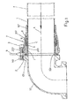
- T indicates a pipe, specifically an aluminum pipe used to convey gas, compressed air, or other fluids, that can be inserted into a joint according to this invention.
- Said joint includes an inner deformable ring 1, made, for example of plastic and suitably shaped.
- This ring includes a first front annular seat 101 which houses a first sealing element 2 and a second inner annular seat 201 which houses two more sealing elements 3 and 4, positioned around the outer surface of pipe T.
- Said ring, bearing the seals 2, 3, and 4 includes, at its front end, an annular step 301, which acts as end stop for the end of pipe T and thus ensures its correct positioning inside the joint.
- Said seals 2, 3, and 4 can be ordinary O-rings or they can be hydraulic seals.
- the inner cross-section of ring 1 has a truncated cone shape; specifically, said cross section narrows going from the rear area where the two seals 3 and 4 are located to the front area where the annular step 301 stopping the end of pipe T is located.
- This truncated cone cross section of ring 1 facilitates the insertion of pipe T and, as we shall see, it undergoes suitable deformation in order to allow a certain compression of seals 3 and 4 on said pipe T.
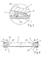
- this joint includes a thrust ring 5, in contact with an annular grab element 6 having, for example, one or more suitably shaped inner edges 106 (see Figure 3 ) made of steel, so that they can partially penetrate, to a suitable depth, into the aluminum pipe T.
- said annular grab element 6 could have a different shape; for example, it could have more than one sharp edges or teeth to grab pipe T.
- the function of said ring 6 is to prevent pipe T from sliding after it has been inserted into ring 1 and the joint has been tightened.
- An external housing 7, preferably made of metal houses inside itself said annular grab element 6 and said thrust ring 5.
- Ring 1 is also almost completely inserted in said external housing 7 and protrudes from said external housing for a short stretch, in which seat 101, housing seal 2, is located.
- Said external housing 7 includes, at the rear, a cylindrical sleeve 107 to insert pipe T and an intermediate part 307 having a truncated cone shape, with an internal conical slope opposite to the internal conical slope of ring 1.
- the conical slope of ring 1 is directed towards the outside of the joint; that is to say, said ring widens towards the side where pipe T is inserted, so as to offer a kind of entrance seat for the pipe.
- the external housing widens towards the inside of the joint, essentially to suitably accommodate rings 1, 5, and 6.
- Said housing 7 includes, at the front, a flange 207 in which a series of number 8 bolts are inserted, directed essentially along the joint's A axis.
- Said external housing 7 (see, Figure 4 for example, also includes a window 407 to mark pipe T, useful, for example, to correctly position pipe T.
- the number 8 bolts can be arranged in a ring pattern around flange 207; their number can vary depending on the requirements and, preferably, they shall be at equal distance from each other.
- a safety spacer ring 9 is also positioned at one side of said external housing 7; when the joint is transported or handled, the spacer, which is removed before assembly, prevents tightening of the inner group, that is, essentially, ring 1 and annular grab element 6, to pipe T.
- Flange 207 faces flange 110 of a joint 10, which is elbow-shaped in the figure, but could also be straight, "L-shaped,” or “T-shaped.”
- the number 8 tightening bolts of the joint are deployed between flange 207 of housing 7 and flange 110 of connecting element 10, as clearly shown in Figure 1 .
- the safety spacer ring 9 is positioned between the two flanges 207 and 110; it is capable of engaging the protruding threaded part of one of the number 8 tightening bolts. Said spacer rings 9 (if more than one) are removed before assembly.
- this joint in its supply and transportation configuration can be as shown in Figure 1 , without pipe T, that is, with housing 7 partially bolted to a connecting element 10 by partial screwing of the number 8 bolts on flanges 207 and 110 and, naturally, with one or more spacer elements 9 in position. All rings 1, 5, and 6 found inside the external housing 7 and seals 2, 3, and 4 are not subject to any compression in this transport configuration.
- pipe T is inserted into inner ring 1 of this joint, until it is stopped against annular step 301; the safety ring 9 is then removed. Said pipe T is inserted very easily along the A axial direction inside ring 1 of this joint, because, as can be seen from the figures and as discussed previously, it does not meet any obstacles or interferences and its positioning is quick and accurate.
- the number 8 bolts in flange 110 of joint 10 are tightened as indicated by the arrows' symbols. Flange 207 of external housing 7 and flange 110 of joint 10 will come into contact with each other.
- said tightening determines the radial pressure of the metal external housing 7 on the plastic inner ring 1, which deforms elastically and tightens radially around pipe T.
- said radial direction is essentially perpendicular to the A axis direction defined with reference to Figure 1 , for example.
- the inside cross-section of ring 1 is now practically cylindrical and the two seals 3 and 4 are suitably compressed between pipe T and the inner surface of ring 1.
- the front seal 2 is also compressed against flange 110 of joint 10.
- the suitable compression of seals 2, 3, and 4 guarantees the optimum sealing of this joint.
- joint 10 The operation of fastening a joint 10 to pipe T through this joint, as described above, is completed if the work space is sufficient, that is, essentially, if there is enough space available to insert pipe T into the joint.
- joint 10 could be of any type, therefore even another section as pipe T or a "T-shaped" element.
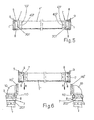
- the pipe section T' is readied, already fitted with a joint according to this invention at each end (see, in particular, figures 4 and 5 ) into which the two sleeves 107 of the two external housings 7 are inserted freely into the ends of pipe T'.
- the pipe T', fitted with the two joints, is inserted along the radial direction R (see figures 6 and 7 ) between the two joints 10.
- the figures show the two joints fitted, on the side opposite to that connecting to pipe T', with additional sections of pipe T connected to the flanges 110 through additional joints according to the invention.
- this joint has an internal deformable ring, which can be made of plastic or metal, which contains all seals, and which is tightened against the flange of the connecting element by screwing the bolts of the external housing.
- the inside ring, internal seals, thrust ring, and grabbing ring have, in their rest position, diameters greater than the outside diameter of the pipe to be inserted; all interferences are thus avoided.
- the outer parts of the rings housed in the external housing adhere perfectly, even at rest, to the inner wall of said external housing.
Landscapes
- Engineering & Computer Science (AREA)
- General Engineering & Computer Science (AREA)
- Mechanical Engineering (AREA)
- Flanged Joints, Insulating Joints, And Other Joints (AREA)
- Quick-Acting Or Multi-Walled Pipe Joints (AREA)
- Joints With Pressure Members (AREA)
Applications Claiming Priority (1)
| Application Number | Priority Date | Filing Date | Title |
|---|---|---|---|
| ITGE20140051 | 2014-06-03 |
Publications (2)
| Publication Number | Publication Date |
|---|---|
| EP2952797A1 true EP2952797A1 (de) | 2015-12-09 |
| EP2952797B1 EP2952797B1 (de) | 2019-09-11 |
Family
ID=51662239
Family Applications (1)
| Application Number | Title | Priority Date | Filing Date |
|---|---|---|---|
| EP15170425.1A Active EP2952797B1 (de) | 2014-06-03 | 2015-06-03 | Anschlussverbindung für rohrleitungen zur förderung von gas, druckluft und anderen flüssigkeiten |
Country Status (3)
| Country | Link |
|---|---|
| US (1) | US9964242B2 (de) |
| EP (1) | EP2952797B1 (de) |
| CN (1) | CN105179837B (de) |
Cited By (2)
| Publication number | Priority date | Publication date | Assignee | Title |
|---|---|---|---|---|
| US20130300111A1 (en) * | 2011-01-14 | 2013-11-14 | Magma Global Limited | Connector Arrangement for Composite Pipe |
| WO2022232201A1 (en) | 2021-04-27 | 2022-11-03 | Oceaneering International Inc | Sealing member for repairing a pipeline and method of use |
Families Citing this family (6)
| Publication number | Priority date | Publication date | Assignee | Title |
|---|---|---|---|---|
| CN105179837B (zh) * | 2014-06-03 | 2019-11-05 | 机械工业股份公司 | 用于运送气体、压缩空气、和其他流体的导管的连接接头 |
| FR3038015B1 (fr) * | 2015-06-23 | 2017-08-11 | Mouvex | Pompe peristaltique avec fixation de tuyau amelioree |
| CN108571630A (zh) * | 2018-07-09 | 2018-09-25 | 安徽恒生科技发展集团有限公司 | 一种防脱型管道连接装置 |
| CN109140070A (zh) * | 2018-09-21 | 2019-01-04 | 孙伟 | 一种应用于高压、高频振动环境的液压管路接头 |
| JP7616768B2 (ja) * | 2021-03-19 | 2025-01-17 | 東京エレクトロン株式会社 | 配管接続構造及び処理装置 |
| EP4083486B1 (de) * | 2021-04-29 | 2023-02-08 | AVS, Ingenieur J.C. Römer GmbH | Leitungskupplung |
Citations (7)
| Publication number | Priority date | Publication date | Assignee | Title |
|---|---|---|---|---|
| FR1201165A (fr) | 1958-08-07 | 1959-12-29 | Louis Lotigie Ets | Raccord pour tubes en matières plastiques souples ou semi-rigides, et particulièrement en polyéthylène |
| FR1574855A (de) * | 1968-05-02 | 1969-07-18 | ||
| US4457541A (en) * | 1980-10-16 | 1984-07-03 | Lucas Industries Limited | Pipe coupling |
| GB2184186A (en) | 1985-11-30 | 1987-06-17 | Tungum Hydraulics Ltd | Improvements in or relating to pipe couplings |
| FR2692644A1 (fr) * | 1992-06-23 | 1993-12-24 | St Mihiel Sa | Dispositif de crampage et d'étanchéité pour brides de raccordement de tuyaux. |
| GB2300680A (en) | 1994-05-04 | 1996-11-13 | Hepworth Building Prod | Spigot and socket pipe joint with intermediate ring |
| EP0742017A2 (de) * | 1995-05-08 | 1996-11-13 | JOHNSON & JOHNSON MEDICAL, INC. | Dampfsterilisation von Erzeugnissen mit Lumen |
Family Cites Families (30)
| Publication number | Priority date | Publication date | Assignee | Title |
|---|---|---|---|---|
| US3223438A (en) * | 1960-06-20 | 1965-12-14 | Purolator Products Inc | Coupling |
| US3301577A (en) * | 1964-01-17 | 1967-01-31 | Gray Tool Co | Transition joint |
| CA975024A (en) * | 1973-07-31 | 1975-09-23 | Coupco Limited | Flange adaptor |
| US4146254A (en) | 1976-03-31 | 1979-03-27 | Bristol Products, Inc. | Coupler for tubing |
| US4073514A (en) | 1976-05-26 | 1978-02-14 | Indian Head Inc. | Combination pipe fitting and retainer ring |
| US4288105A (en) | 1979-02-21 | 1981-09-08 | Resistoflex Corporation | Pipe union with both pre-load dependent and independent seals |
| US4299413A (en) | 1979-06-26 | 1981-11-10 | Ciba-Geigy Corporation | Pipe coupling |
| US4407526A (en) | 1981-01-05 | 1983-10-04 | Perfection Corporation | Tab-type coupling and method |
| US4568109A (en) | 1983-02-15 | 1986-02-04 | The Dow Chemical Company | Pipe aligning and joining |
| US4832379A (en) * | 1987-01-28 | 1989-05-23 | The Pipe Line Development Company | Collet grip riser fitting |
| CA2032830C (en) | 1990-12-20 | 1994-07-26 | R.S.T. Instruments Ltd. | Coupling |
| SE9300365L (sv) | 1993-02-05 | 1994-08-01 | Wirsbo Bruks Ab | Förfarande för upprättande av en rörförbindning samt för användning vid förfarandet lämpat rörförbindningsstycke |
| EP0972981A3 (de) | 1994-09-14 | 2000-04-26 | John Derek Guest | Klemmring |
| US5549334A (en) | 1994-10-20 | 1996-08-27 | Miller Pipeline Corporation | Retaining band assembly for internal pipe seals |
| US5842726A (en) | 1996-02-27 | 1998-12-01 | Smith-Blair, Inc. | Preformed transition pipe coupling |
| US5803513A (en) * | 1996-06-13 | 1998-09-08 | Richardson; Robert J. | Restrained sealed bolted joints of fluid piping systems, inclusive of an improved gland, an added compression control ring, and/or added skid pads placed on a grip ring |
| IL127327A (en) | 1998-08-24 | 2002-07-25 | Plasson Ltd | Hose coupler |
| US7104573B2 (en) * | 2000-06-08 | 2006-09-12 | United States Pipe And Foundy Company, Llc | Energized restraining gasket for mechanical joints of pipes |
| US7108289B1 (en) * | 2000-06-08 | 2006-09-19 | United States Pipe And Foundry Company, Llc | Restraining gasket for mechanical joints of pipes |
| CA2463004C (en) * | 2003-04-01 | 2009-06-02 | Dale Barron | Pipe coupling device |
| US6945570B2 (en) * | 2003-05-19 | 2005-09-20 | S & B Technical Products, Inc. | Self restraining gasket and pipe joint |
| US7125054B2 (en) * | 2003-05-19 | 2006-10-24 | S & B Technical Products, Inc. | Self restraining gasket and pipe joint |
| WO2008030392A2 (en) * | 2006-09-06 | 2008-03-13 | Victaulic Company | Banded flexible pipe coupling |
| US9611958B1 (en) * | 2007-01-05 | 2017-04-04 | Zurn Industries, Llc | Combination mechanical/fusion pipe fitting with push connect coupling arrangement |
| US8480134B2 (en) * | 2007-05-25 | 2013-07-09 | Quick Fitting, Inc. | Piping joint assembly system and method with sealing ring stabilizer |
| US8205915B1 (en) | 2007-05-25 | 2012-06-26 | Quick Fitting, Inc. | Piping joint assembly system and method |
| US20090273184A1 (en) * | 2008-04-30 | 2009-11-05 | Michael Wright | Self restrained joint for ductile iron pipe and fittings |
| CA2732537C (en) | 2010-02-26 | 2017-08-01 | Mueller International, Llc | Pipe coupling device |
| CN201715134U (zh) * | 2010-07-09 | 2011-01-19 | 兴化市通科机械有限公司 | 管道快修套管接头 |
| CN105179837B (zh) * | 2014-06-03 | 2019-11-05 | 机械工业股份公司 | 用于运送气体、压缩空气、和其他流体的导管的连接接头 |
-
2015
- 2015-06-02 CN CN201510294579.1A patent/CN105179837B/zh active Active
- 2015-06-03 US US14/729,888 patent/US9964242B2/en active Active
- 2015-06-03 EP EP15170425.1A patent/EP2952797B1/de active Active
Patent Citations (7)
| Publication number | Priority date | Publication date | Assignee | Title |
|---|---|---|---|---|
| FR1201165A (fr) | 1958-08-07 | 1959-12-29 | Louis Lotigie Ets | Raccord pour tubes en matières plastiques souples ou semi-rigides, et particulièrement en polyéthylène |
| FR1574855A (de) * | 1968-05-02 | 1969-07-18 | ||
| US4457541A (en) * | 1980-10-16 | 1984-07-03 | Lucas Industries Limited | Pipe coupling |
| GB2184186A (en) | 1985-11-30 | 1987-06-17 | Tungum Hydraulics Ltd | Improvements in or relating to pipe couplings |
| FR2692644A1 (fr) * | 1992-06-23 | 1993-12-24 | St Mihiel Sa | Dispositif de crampage et d'étanchéité pour brides de raccordement de tuyaux. |
| GB2300680A (en) | 1994-05-04 | 1996-11-13 | Hepworth Building Prod | Spigot and socket pipe joint with intermediate ring |
| EP0742017A2 (de) * | 1995-05-08 | 1996-11-13 | JOHNSON & JOHNSON MEDICAL, INC. | Dampfsterilisation von Erzeugnissen mit Lumen |
Cited By (5)
| Publication number | Priority date | Publication date | Assignee | Title |
|---|---|---|---|---|
| US20130300111A1 (en) * | 2011-01-14 | 2013-11-14 | Magma Global Limited | Connector Arrangement for Composite Pipe |
| WO2022232201A1 (en) | 2021-04-27 | 2022-11-03 | Oceaneering International Inc | Sealing member for repairing a pipeline and method of use |
| WO2022232202A1 (en) | 2021-04-27 | 2022-11-03 | Oceaneering International Inc | Pipeline spool piece seal assembly and method of use |
| EP4314621A4 (de) * | 2021-04-27 | 2025-02-19 | Oceaneering International, Inc. | Dichtungselement zur reparatur einer rohrleitung und verfahren zur verwendung |
| EP4314612A4 (de) * | 2021-04-27 | 2025-03-19 | Oceaneering International, Inc. | Dichtungsanordnung für rohrleitungsspulenteil und verfahren zur verwendung |
Also Published As
| Publication number | Publication date |
|---|---|
| US9964242B2 (en) | 2018-05-08 |
| CN105179837B (zh) | 2019-11-05 |
| EP2952797B1 (de) | 2019-09-11 |
| US20150377392A1 (en) | 2015-12-31 |
| CN105179837A (zh) | 2015-12-23 |
Similar Documents
| Publication | Publication Date | Title |
|---|---|---|
| US9964242B2 (en) | Connection joint for pipes to convey gas, compressed air and other fluids | |
| EP2825805B1 (de) | Armatur mit einem zugmechanismus | |
| EP3025083B1 (de) | Verbesserungen an und in zusammenhang mit rohrverbindungen | |
| EP2681478B1 (de) | Rohrverbindung | |
| US8096591B2 (en) | Split joint restraint device with dual pipe size capability | |
| US20150276103A1 (en) | Pipe joint | |
| US20110291409A1 (en) | Pipe Gripping Elements with Buttress Pockets and Pipe Joint Restraints Incorporating Same | |
| US20120217743A1 (en) | Pipe coupling assembly with sleeve locking tabs and associated methods | |
| JP7660479B2 (ja) | パイプライナー端部終端 | |
| GB2485350A (en) | Pipe coupling | |
| WO2009103995A1 (en) | Coupling | |
| US20120056419A1 (en) | Pipe coupling | |
| CA2732048C (en) | Split joint restraint device with dual pipe size capability | |
| US20190154175A1 (en) | Coupling for forming a sealed joint between first and second tubular members | |
| RU2752226C2 (ru) | Фитинг высокого давления | |
| US10323783B2 (en) | Fusion tee outlet abandonment device | |
| US20190376634A1 (en) | Trenchless mechanical lining system for continuous repair of underground pipes and culverts, and method of installation | |
| WO2010106369A2 (en) | Pipe coupling |
Legal Events
| Date | Code | Title | Description |
|---|---|---|---|
| PUAI | Public reference made under article 153(3) epc to a published international application that has entered the european phase |
Free format text: ORIGINAL CODE: 0009012 |
|
| 17P | Request for examination filed |
Effective date: 20150603 |
|
| AK | Designated contracting states |
Kind code of ref document: A1 Designated state(s): AL AT BE BG CH CY CZ DE DK EE ES FI FR GB GR HR HU IE IS IT LI LT LU LV MC MK MT NL NO PL PT RO RS SE SI SK SM TR |
|
| AX | Request for extension of the european patent |
Extension state: BA ME |
|
| GRAP | Despatch of communication of intention to grant a patent |
Free format text: ORIGINAL CODE: EPIDOSNIGR1 |
|
| STAA | Information on the status of an ep patent application or granted ep patent |
Free format text: STATUS: GRANT OF PATENT IS INTENDED |
|
| RIC1 | Information provided on ipc code assigned before grant |
Ipc: F16L 23/032 20060101ALI20180913BHEP Ipc: F16L 21/08 20060101AFI20180913BHEP Ipc: F16L 23/028 20060101ALI20180913BHEP Ipc: F16L 23/024 20060101ALI20180913BHEP |
|
| INTG | Intention to grant announced |
Effective date: 20181012 |
|
| GRAJ | Information related to disapproval of communication of intention to grant by the applicant or resumption of examination proceedings by the epo deleted |
Free format text: ORIGINAL CODE: EPIDOSDIGR1 |
|
| STAA | Information on the status of an ep patent application or granted ep patent |
Free format text: STATUS: REQUEST FOR EXAMINATION WAS MADE |
|
| GRAP | Despatch of communication of intention to grant a patent |
Free format text: ORIGINAL CODE: EPIDOSNIGR1 |
|
| STAA | Information on the status of an ep patent application or granted ep patent |
Free format text: STATUS: GRANT OF PATENT IS INTENDED |
|
| INTC | Intention to grant announced (deleted) | ||
| INTG | Intention to grant announced |
Effective date: 20190206 |
|
| GRAS | Grant fee paid |
Free format text: ORIGINAL CODE: EPIDOSNIGR3 |
|
| GRAJ | Information related to disapproval of communication of intention to grant by the applicant or resumption of examination proceedings by the epo deleted |
Free format text: ORIGINAL CODE: EPIDOSDIGR1 |
|
| GRAL | Information related to payment of fee for publishing/printing deleted |
Free format text: ORIGINAL CODE: EPIDOSDIGR3 |
|
| STAA | Information on the status of an ep patent application or granted ep patent |
Free format text: STATUS: REQUEST FOR EXAMINATION WAS MADE |
|
| GRAP | Despatch of communication of intention to grant a patent |
Free format text: ORIGINAL CODE: EPIDOSNIGR1 |
|
| STAA | Information on the status of an ep patent application or granted ep patent |
Free format text: STATUS: GRANT OF PATENT IS INTENDED |
|
| INTC | Intention to grant announced (deleted) | ||
| INTG | Intention to grant announced |
Effective date: 20190704 |
|
| GRAA | (expected) grant |
Free format text: ORIGINAL CODE: 0009210 |
|
| STAA | Information on the status of an ep patent application or granted ep patent |
Free format text: STATUS: THE PATENT HAS BEEN GRANTED |
|
| AK | Designated contracting states |
Kind code of ref document: B1 Designated state(s): AL AT BE BG CH CY CZ DE DK EE ES FI FR GB GR HR HU IE IS IT LI LT LU LV MC MK MT NL NO PL PT RO RS SE SI SK SM TR |
|
| REG | Reference to a national code |
Ref country code: GB Ref legal event code: FG4D |
|
| REG | Reference to a national code |
Ref country code: CH Ref legal event code: EP |
|
| REG | Reference to a national code |
Ref country code: AT Ref legal event code: REF Ref document number: 1178872 Country of ref document: AT Kind code of ref document: T Effective date: 20190915 |
|
| REG | Reference to a national code |
Ref country code: DE Ref legal event code: R096 Ref document number: 602015037624 Country of ref document: DE Ref country code: IE Ref legal event code: FG4D |
|
| REG | Reference to a national code |
Ref country code: NL Ref legal event code: MP Effective date: 20190911 |
|
| REG | Reference to a national code |
Ref country code: LT Ref legal event code: MG4D |
|
| PG25 | Lapsed in a contracting state [announced via postgrant information from national office to epo] |
Ref country code: FI Free format text: LAPSE BECAUSE OF FAILURE TO SUBMIT A TRANSLATION OF THE DESCRIPTION OR TO PAY THE FEE WITHIN THE PRESCRIBED TIME-LIMIT Effective date: 20190911 Ref country code: SE Free format text: LAPSE BECAUSE OF FAILURE TO SUBMIT A TRANSLATION OF THE DESCRIPTION OR TO PAY THE FEE WITHIN THE PRESCRIBED TIME-LIMIT Effective date: 20190911 Ref country code: HR Free format text: LAPSE BECAUSE OF FAILURE TO SUBMIT A TRANSLATION OF THE DESCRIPTION OR TO PAY THE FEE WITHIN THE PRESCRIBED TIME-LIMIT Effective date: 20190911 Ref country code: LT Free format text: LAPSE BECAUSE OF FAILURE TO SUBMIT A TRANSLATION OF THE DESCRIPTION OR TO PAY THE FEE WITHIN THE PRESCRIBED TIME-LIMIT Effective date: 20190911 Ref country code: NO Free format text: LAPSE BECAUSE OF FAILURE TO SUBMIT A TRANSLATION OF THE DESCRIPTION OR TO PAY THE FEE WITHIN THE PRESCRIBED TIME-LIMIT Effective date: 20191211 Ref country code: BG Free format text: LAPSE BECAUSE OF FAILURE TO SUBMIT A TRANSLATION OF THE DESCRIPTION OR TO PAY THE FEE WITHIN THE PRESCRIBED TIME-LIMIT Effective date: 20191211 |
|
| PG25 | Lapsed in a contracting state [announced via postgrant information from national office to epo] |
Ref country code: AL Free format text: LAPSE BECAUSE OF FAILURE TO SUBMIT A TRANSLATION OF THE DESCRIPTION OR TO PAY THE FEE WITHIN THE PRESCRIBED TIME-LIMIT Effective date: 20190911 Ref country code: ES Free format text: LAPSE BECAUSE OF FAILURE TO SUBMIT A TRANSLATION OF THE DESCRIPTION OR TO PAY THE FEE WITHIN THE PRESCRIBED TIME-LIMIT Effective date: 20190911 Ref country code: LV Free format text: LAPSE BECAUSE OF FAILURE TO SUBMIT A TRANSLATION OF THE DESCRIPTION OR TO PAY THE FEE WITHIN THE PRESCRIBED TIME-LIMIT Effective date: 20190911 Ref country code: RS Free format text: LAPSE BECAUSE OF FAILURE TO SUBMIT A TRANSLATION OF THE DESCRIPTION OR TO PAY THE FEE WITHIN THE PRESCRIBED TIME-LIMIT Effective date: 20190911 Ref country code: GR Free format text: LAPSE BECAUSE OF FAILURE TO SUBMIT A TRANSLATION OF THE DESCRIPTION OR TO PAY THE FEE WITHIN THE PRESCRIBED TIME-LIMIT Effective date: 20191212 |
|
| REG | Reference to a national code |
Ref country code: AT Ref legal event code: MK05 Ref document number: 1178872 Country of ref document: AT Kind code of ref document: T Effective date: 20190911 |
|
| PG25 | Lapsed in a contracting state [announced via postgrant information from national office to epo] |
Ref country code: IT Free format text: LAPSE BECAUSE OF FAILURE TO SUBMIT A TRANSLATION OF THE DESCRIPTION OR TO PAY THE FEE WITHIN THE PRESCRIBED TIME-LIMIT Effective date: 20190911 Ref country code: RO Free format text: LAPSE BECAUSE OF FAILURE TO SUBMIT A TRANSLATION OF THE DESCRIPTION OR TO PAY THE FEE WITHIN THE PRESCRIBED TIME-LIMIT Effective date: 20190911 Ref country code: PL Free format text: LAPSE BECAUSE OF FAILURE TO SUBMIT A TRANSLATION OF THE DESCRIPTION OR TO PAY THE FEE WITHIN THE PRESCRIBED TIME-LIMIT Effective date: 20190911 Ref country code: PT Free format text: LAPSE BECAUSE OF FAILURE TO SUBMIT A TRANSLATION OF THE DESCRIPTION OR TO PAY THE FEE WITHIN THE PRESCRIBED TIME-LIMIT Effective date: 20200113 Ref country code: NL Free format text: LAPSE BECAUSE OF FAILURE TO SUBMIT A TRANSLATION OF THE DESCRIPTION OR TO PAY THE FEE WITHIN THE PRESCRIBED TIME-LIMIT Effective date: 20190911 Ref country code: AT Free format text: LAPSE BECAUSE OF FAILURE TO SUBMIT A TRANSLATION OF THE DESCRIPTION OR TO PAY THE FEE WITHIN THE PRESCRIBED TIME-LIMIT Effective date: 20190911 Ref country code: EE Free format text: LAPSE BECAUSE OF FAILURE TO SUBMIT A TRANSLATION OF THE DESCRIPTION OR TO PAY THE FEE WITHIN THE PRESCRIBED TIME-LIMIT Effective date: 20190911 |
|
| PG25 | Lapsed in a contracting state [announced via postgrant information from national office to epo] |
Ref country code: CZ Free format text: LAPSE BECAUSE OF FAILURE TO SUBMIT A TRANSLATION OF THE DESCRIPTION OR TO PAY THE FEE WITHIN THE PRESCRIBED TIME-LIMIT Effective date: 20190911 Ref country code: SK Free format text: LAPSE BECAUSE OF FAILURE TO SUBMIT A TRANSLATION OF THE DESCRIPTION OR TO PAY THE FEE WITHIN THE PRESCRIBED TIME-LIMIT Effective date: 20190911 Ref country code: IS Free format text: LAPSE BECAUSE OF FAILURE TO SUBMIT A TRANSLATION OF THE DESCRIPTION OR TO PAY THE FEE WITHIN THE PRESCRIBED TIME-LIMIT Effective date: 20200224 Ref country code: SM Free format text: LAPSE BECAUSE OF FAILURE TO SUBMIT A TRANSLATION OF THE DESCRIPTION OR TO PAY THE FEE WITHIN THE PRESCRIBED TIME-LIMIT Effective date: 20190911 |
|
| REG | Reference to a national code |
Ref country code: DE Ref legal event code: R097 Ref document number: 602015037624 Country of ref document: DE |
|
| PLBE | No opposition filed within time limit |
Free format text: ORIGINAL CODE: 0009261 |
|
| STAA | Information on the status of an ep patent application or granted ep patent |
Free format text: STATUS: NO OPPOSITION FILED WITHIN TIME LIMIT |
|
| PG2D | Information on lapse in contracting state deleted |
Ref country code: IS |
|
| PG25 | Lapsed in a contracting state [announced via postgrant information from national office to epo] |
Ref country code: DK Free format text: LAPSE BECAUSE OF FAILURE TO SUBMIT A TRANSLATION OF THE DESCRIPTION OR TO PAY THE FEE WITHIN THE PRESCRIBED TIME-LIMIT Effective date: 20190911 Ref country code: IS Free format text: LAPSE BECAUSE OF FAILURE TO SUBMIT A TRANSLATION OF THE DESCRIPTION OR TO PAY THE FEE WITHIN THE PRESCRIBED TIME-LIMIT Effective date: 20200112 |
|
| 26N | No opposition filed |
Effective date: 20200615 |
|
| PG25 | Lapsed in a contracting state [announced via postgrant information from national office to epo] |
Ref country code: SI Free format text: LAPSE BECAUSE OF FAILURE TO SUBMIT A TRANSLATION OF THE DESCRIPTION OR TO PAY THE FEE WITHIN THE PRESCRIBED TIME-LIMIT Effective date: 20190911 |
|
| REG | Reference to a national code |
Ref country code: DE Ref legal event code: R082 Ref document number: 602015037624 Country of ref document: DE Representative=s name: MURGITROYD GERMANY PATENTANWALTSGESELLSCHAFT M, DE Ref country code: DE Ref legal event code: R082 Ref document number: 602015037624 Country of ref document: DE Representative=s name: HL KEMPNER PATENTANWALT, RECHTSANWALT, SOLICIT, DE Ref country code: DE Ref legal event code: R082 Ref document number: 602015037624 Country of ref document: DE Representative=s name: MURGITROYD & COMPANY, DE |
|
| PG25 | Lapsed in a contracting state [announced via postgrant information from national office to epo] |
Ref country code: MC Free format text: LAPSE BECAUSE OF FAILURE TO SUBMIT A TRANSLATION OF THE DESCRIPTION OR TO PAY THE FEE WITHIN THE PRESCRIBED TIME-LIMIT Effective date: 20190911 |
|
| REG | Reference to a national code |
Ref country code: CH Ref legal event code: PL |
|
| PG25 | Lapsed in a contracting state [announced via postgrant information from national office to epo] |
Ref country code: LU Free format text: LAPSE BECAUSE OF NON-PAYMENT OF DUE FEES Effective date: 20200603 |
|
| REG | Reference to a national code |
Ref country code: BE Ref legal event code: MM Effective date: 20200630 |
|
| REG | Reference to a national code |
Ref country code: DE Ref legal event code: R082 Ref document number: 602015037624 Country of ref document: DE Representative=s name: MURGITROYD GERMANY PATENTANWALTSGESELLSCHAFT M, DE Ref country code: DE Ref legal event code: R082 Ref document number: 602015037624 Country of ref document: DE Representative=s name: MURGITROYD & COMPANY, DE |
|
| PG25 | Lapsed in a contracting state [announced via postgrant information from national office to epo] |
Ref country code: CH Free format text: LAPSE BECAUSE OF NON-PAYMENT OF DUE FEES Effective date: 20200630 Ref country code: IE Free format text: LAPSE BECAUSE OF NON-PAYMENT OF DUE FEES Effective date: 20200603 Ref country code: LI Free format text: LAPSE BECAUSE OF NON-PAYMENT OF DUE FEES Effective date: 20200630 |
|
| PG25 | Lapsed in a contracting state [announced via postgrant information from national office to epo] |
Ref country code: BE Free format text: LAPSE BECAUSE OF NON-PAYMENT OF DUE FEES Effective date: 20200630 |
|
| PG25 | Lapsed in a contracting state [announced via postgrant information from national office to epo] |
Ref country code: TR Free format text: LAPSE BECAUSE OF FAILURE TO SUBMIT A TRANSLATION OF THE DESCRIPTION OR TO PAY THE FEE WITHIN THE PRESCRIBED TIME-LIMIT Effective date: 20190911 Ref country code: MT Free format text: LAPSE BECAUSE OF FAILURE TO SUBMIT A TRANSLATION OF THE DESCRIPTION OR TO PAY THE FEE WITHIN THE PRESCRIBED TIME-LIMIT Effective date: 20190911 Ref country code: CY Free format text: LAPSE BECAUSE OF FAILURE TO SUBMIT A TRANSLATION OF THE DESCRIPTION OR TO PAY THE FEE WITHIN THE PRESCRIBED TIME-LIMIT Effective date: 20190911 |
|
| PG25 | Lapsed in a contracting state [announced via postgrant information from national office to epo] |
Ref country code: MK Free format text: LAPSE BECAUSE OF FAILURE TO SUBMIT A TRANSLATION OF THE DESCRIPTION OR TO PAY THE FEE WITHIN THE PRESCRIBED TIME-LIMIT Effective date: 20190911 |
|
| PGFP | Annual fee paid to national office [announced via postgrant information from national office to epo] |
Ref country code: FR Payment date: 20220624 Year of fee payment: 8 |
|
| P01 | Opt-out of the competence of the unified patent court (upc) registered |
Effective date: 20230523 |
|
| PG25 | Lapsed in a contracting state [announced via postgrant information from national office to epo] |
Ref country code: FR Free format text: LAPSE BECAUSE OF NON-PAYMENT OF DUE FEES Effective date: 20230630 |
|
| PGFP | Annual fee paid to national office [announced via postgrant information from national office to epo] |
Ref country code: GB Payment date: 20250627 Year of fee payment: 11 |
|
| PGFP | Annual fee paid to national office [announced via postgrant information from national office to epo] |
Ref country code: DE Payment date: 20250630 Year of fee payment: 11 |