EP2952859B1 - Procédé et système pour déterminer un volume de liquide s'écoulant à travers un conduit - Google Patents
Procédé et système pour déterminer un volume de liquide s'écoulant à travers un conduit Download PDFInfo
- Publication number
- EP2952859B1 EP2952859B1 EP14171535.9A EP14171535A EP2952859B1 EP 2952859 B1 EP2952859 B1 EP 2952859B1 EP 14171535 A EP14171535 A EP 14171535A EP 2952859 B1 EP2952859 B1 EP 2952859B1
- Authority
- EP
- European Patent Office
- Prior art keywords
- volume
- value
- flow meter
- pulses
- liquid
- Prior art date
- Legal status (The legal status is an assumption and is not a legal conclusion. Google has not performed a legal analysis and makes no representation as to the accuracy of the status listed.)
- Active
Links
Images


Classifications
-
- G—PHYSICS
- G01—MEASURING; TESTING
- G01F—MEASURING VOLUME, VOLUME FLOW, MASS FLOW OR LIQUID LEVEL; METERING BY VOLUME
- G01F3/00—Measuring the volume flow of fluids or fluent solid material wherein the fluid passes through the meter in successive and more or less isolated quantities, the meter being driven by the flow
-
- G—PHYSICS
- G01—MEASURING; TESTING
- G01F—MEASURING VOLUME, VOLUME FLOW, MASS FLOW OR LIQUID LEVEL; METERING BY VOLUME
- G01F1/00—Measuring the volume flow or mass flow of fluid or fluent solid material wherein the fluid passes through a meter in a continuous flow
- G01F1/05—Measuring the volume flow or mass flow of fluid or fluent solid material wherein the fluid passes through a meter in a continuous flow by using mechanical effects
- G01F1/06—Measuring the volume flow or mass flow of fluid or fluent solid material wherein the fluid passes through a meter in a continuous flow by using mechanical effects using rotating vanes with tangential admission
- G01F1/065—Measuring the volume flow or mass flow of fluid or fluent solid material wherein the fluid passes through a meter in a continuous flow by using mechanical effects using rotating vanes with tangential admission with radiation as transfer means to the indicating device, e.g. light transmission
-
- G—PHYSICS
- G01—MEASURING; TESTING
- G01F—MEASURING VOLUME, VOLUME FLOW, MASS FLOW OR LIQUID LEVEL; METERING BY VOLUME
- G01F1/00—Measuring the volume flow or mass flow of fluid or fluent solid material wherein the fluid passes through a meter in a continuous flow
- G01F1/05—Measuring the volume flow or mass flow of fluid or fluent solid material wherein the fluid passes through a meter in a continuous flow by using mechanical effects
- G01F1/06—Measuring the volume flow or mass flow of fluid or fluent solid material wherein the fluid passes through a meter in a continuous flow by using mechanical effects using rotating vanes with tangential admission
- G01F1/075—Measuring the volume flow or mass flow of fluid or fluent solid material wherein the fluid passes through a meter in a continuous flow by using mechanical effects using rotating vanes with tangential admission with magnetic or electromagnetic coupling to the indicating device
-
- G—PHYSICS
- G01—MEASURING; TESTING
- G01F—MEASURING VOLUME, VOLUME FLOW, MASS FLOW OR LIQUID LEVEL; METERING BY VOLUME
- G01F15/00—Details of, or accessories for, apparatus of groups G01F1/00 - G01F13/00 insofar as such details or appliances are not adapted to particular types of such apparatus
- G01F15/07—Integration to give total flow, e.g. using mechanically-operated integrating mechanism
Definitions
- the invention relates to a method of determining a volume of liquid flowing through a conduit, including:
- the invention also relates to a system for determining a volume of liquid flowing through a conduit, including:
- the invention also relates to an apparatus including:
- the invention also relates to a computer program.
- US 5,574,229 discloses a method of making an electronic water meter to accurately measure the volume of water flowing through the meter especially at low flow rates to detect leakage, the meter comprising a body member through which the water flows, a magnetic rotor means mounted on the body and movable by the flow of water to produce magnetic signals into digital signals which are frequency pulse signals, and an electronic correction circuit means mounted on the meter body member to correct for non-proportionality between water flow and rotor means movement frequency.
- a "D" coefficient or Division coefficient is the number of pulses from the rotor that correspond to a determined unit of volume (litres, gallons, cubic feet etc.). A set of tests is performed on each meter rotor of a production run.
- the test finds D coefficients at three flow rates.
- the electronic correction system includes a tachometer or frequency meter, which counts the number of times that the digitised signal changes over a period of time, using an oscillator for the determination of time.
- the calculation "D" (S) (number of rotor pulses/unit volume) is done by consulting the electronic correction system memory's data base and logic equations.
- a programmable divisor/divider is carried out with one or various preselectable binary counters. Resulting volume pulses can be sent to a remote accumulation unit or can be accumulated by the electronic correction system.
- WO 2007/086049 discloses a self-calibrating fluid flow meter that generates pulses proportional to the flow therethrough both at high and low flow rates.
- a meter optimised for use as a water meter is of the type having a chamber in which a rotatable part is revolved by fluid flowing through the chamber.
- a rotor is mechanically linked by a shaft to an impeller, which impeller rotates as a result of fluid flow through the meter. It is possible to pick up four flow pulses for each rotation of the impeller.
- testing time interval with an arbitrary default of e.g. 4 seconds, which default is increased at the low flow rates to e.g. 30 seconds.
- the time interval from the start time of the first pulse to the end time of the last pulse is then measured, and in order to obtain a full pulse after said end time, one waits for the next pulse stop time. Pulses are counted in this time.
- the electronic flow meter records the time between pulses, i.e. the change of state, as well as the number of pulses in the time interval being tested. The higher the flow rate, the shorter the time between pulses (TBP) and the lower the flow rate, the longer the TBP.
- TBP time between pulses
- TBP versus volume per pulse is in the calibration software, then the curve may be cut up using a predetermined algorithm. Typically, zero order curves will be used where changes are small in the meter curve characteristics, i.e. relating to high flows, and first order curves will be used where changes are great, typically at low flows.
- a text table of volume per pulse and TBP for zero order and, additionally, slope for first order is downloaded into a meter microprocessor.
- a problem of the known method is that it must be carried out in the factory for each flow meter. This is because the variation in measurement error across a range of flow meters of the same type is relatively large. Thus, the known method requires that a calibration curve be determined experimentally for each individual flow meter by a manufacturer.
- This object is achieved according to a first aspect by the method according to the invention, which is characterised by determining the volume as a pre-determined value ( z ) upon determining that the measure ( f ) is indicative of a pulse frequency equal to or lower than the certain value ( y ).
- the pre-determined value is a value typically dependent on the conditions of use of the flow meter, typically on the characteristics of the appliance or appliances to which the conduit leads.
- the method includes receiving a signal from a flow meter including a rotor drivable by the fluid, wherein the signal is representative of a pulse sequence obtainable by detecting passage of at least one signalling device of which movement is at least synchronised with that of the rotor.
- the method is suitable for use with (axial) turbine flow meters, cylindrical piston meters, oval disk meters and, in particular, jet impeller flow meters.
- the latter are suitable for measuring flows of liquid to or through appliances for dispensing beverages, in particular intermittent flows of quantities of liquid corresponding to servings of particular sizes (a glass, a carafe, a cup, a tankard, etc.). They are relatively cheap and relatively compact. To avoid causing relatively large pressure drops in the flow meter, the nozzle from which the jet emerges should not be very narrow. This causes some inaccuracy at low rates of flow due to bypass flow - a problem also encountered with the other types of flow meter mentioned above. The method outlined herein addresses this.
- the appliance dispensing the beverage will be set to draw quantities of liquid of particular volumes, the smallest of which can be stored as the pre-determined value.
- the method is relatively accurate, in that it includes determining a number of the pulses within a period of time; determining a measure of a pulse frequency within the period of time; and determining the volume as a function of a number of pulses within the period of time. For this, a calibration factor is required, but it varies relatively little between flow meters of the same type, so that its value need not be determined separately for each individual flow meter.
- the volume of liquid determined to flow through the conduit for the time interval under consideration may be added to a running total volume.
- the determination may be carried out for each of multiple pulse sequences of finite length, corresponding to discrete time intervals.
- the determination may be repeated and the determined volumes added to a running total until the end of a certain time period or a certain total value has been reached, for example, or until a first of these conditions has been met.
- An embodiment includes identifying start and end points of the time interval ( ⁇ t ) by detecting a start and cessation of liquid flow through the conduit.
- This embodiment is for use when supplying liquid to an appliance arranged to draw liquid in bursts corresponding to discrete portions.
- the accuracy of this embodiment is relatively high, in that, when a large quantity is drawn, this is generally at a high rate. A small quantity is generally drawn at a relatively low rate, at which a volume determination based on pulse count is relatively inaccurate for many types of mechanical flow meter.
- Signal processing is carried out relatively efficiently in this embodiment, because it is based on variable-length time intervals. When the flow of liquid is interrupted, volume determinations are not carried out. When a larger quantity of liquid flows through the conduit, the volume of this quantity is determined in a single iteration of the method.
- the start and end points of the time interval ( ⁇ t ) are identified by comparing a time between successive pulses with a certain threshold value.
- the flow meter is adapted to provide pulses at a minimum frequency when liquid flows at a higher than a minimum expected volumetric rate of flow.
- the minimum frequency is chosen such that its inverse is appreciably smaller than the typical duration of an interruption in the flow of liquid.
- interruptions in flow can be distinguished from flow at small volumetric flow rates and thereby the start and end points of the time interval determined relatively accurately.
- the typical duration of an interruption in the flow of liquid may correspond to a typical duration of a pause between dispensing events of a beverage dispenser supplied through the conduit and/or to the minimum length of time from finishing the preparation of one beverage to commencing the preparation of next beverage in an appliance for preparing a beverage from liquid supplied through the conduit.
- the volume is determined as the pre-determined value ( y ) if the measure ( f ) is indicative of a pulse frequency equal to or lower than the certain value ( y ), but only if the number ( N ) of pulses exceeds a certain minimum value.
- This embodiment ensures that a volume corresponding to the certain value is not determined, and possibly added to a running total, when spurious pulses are detected. Only finite pulse sequences of a certain minimum length are taken into account. Thus, vibration or pressure changes not associated with a flow of liquid do not lead to the false determination that a quantity of the certain volume has passed through the conduit.
- the volume is determined as the pre-determined value ( y ) if the measure ( f ) is indicative of a pulse frequency equal to or lower than the certain value ( y ), but only if the volume ( V ) calculated as a function of the number of pulses within the time interval ( ⁇ t ) has a smaller value than a certain maximum value, e.g. a certain maximum value corresponding to the pre-determined value ( z ) of the volume.
- a certain maximum value e.g. a certain maximum value corresponding to the pre-determined value ( z ) of the volume.
- the volume of liquid flowing through the conduit to an appliance including at least a device for dispensing a beverage is determined.
- the volume of liquid flowing from a mains water supply is determined.
- the flow meter can be configured to provide a particular maximum pressure drop. This defines the range of flow rate values expected to occur for given volumes of quantities of liquid flowing through the conduit. There is thus a relatively good correlation between flow rate and volume.
- the flow meter comprises a jet impeller flow meter.
- the system according to the invention is characterised in that the signal processing unit is configured to determine the volume as a pre-determined value ( z ) upon determining that the measure ( f ) is indicative of a pulse frequency equal to or lower than the certain value ( y ).
- the system may be configured to carry out a method according to the invention.
- the apparatus includes a flow meter, the flow meter including a rotor drivable by a liquid passing through the flow meter, at least one signalling device of which movement is at least synchronised with that of the rotor and at least one sensor for detecting passage of at least one of the at least one signalling devices and generating a signal representative of a pulse sequence, each detected passage resulting in at least one pulse; and a system according to the invention for processing the signal.
- the signalling device or devices may be comprised in the rotor.
- the apparatus further includes an appliance for dispensing a beverage, e.g. a hot beverage.
- a beverage e.g. a hot beverage.
- the appliance may be suitable for preparing a hot beverage by extraction, e.g. espresso coffee.
- An embodiment of the apparatus further includes a liquid treatment device including a replaceable liquid treatment cartridge.
- the replaceable liquid treatment cartridge may contain at least a liquid treatment medium for the treatment of liquid by sorption, which in the present context includes the treatment of liquid by ion exchange.
- the liquid treatment medium may include a weakly acidic cation exchange resin. This resin may be at least partly in the hydrogen form.
- Such a liquid treatment device typically includes a device for blending liquid treated by contacting with the cation exchange resin with liquid untreated or treated to a lesser extent by contacting with the cation exchange resin. In such a device it is useful to determine the relative volumes of the liquid passed through a conduit to the liquid treatment cartridge and that bypassing some or all of the cation exchange resin in the liquid treatment cartridge.
- the liquid treatment medium in the liquid treatment cartridge may include activated carbon as an alternative to or in addition to the cation exchange resin.
- An embodiment of the apparatus wherein the system is configured to carry out the volume determination repeatedly and to add each determined volume to a running total, further includes a device for providing an output signal when the running total has reached a maximum total volume.
- the liquid treatment medium in the liquid treatment cartridge will be exhausted after a certain volume of water has been treated.
- the need to replace the cartridge can be signalled relatively accurately.
- the output signal is provided when the earliest of two events occurs, namely the running total's reaching the maximum total volume and the elapse of a certain maximum period of time since a point in time at which a signal associated with replacement of the liquid treatment cartridge is received.
- the flow meter comprises a jet impeller flow meter.
- the flow meter may be a multiple-jet or single-jet impeller flow meter.
- a computer program including a set of instructions capable, when incorporated in a machine-readable medium, of causing a system having information processing capability to execute a method according to the invention.
- An apparatus ( Fig. 1 ) for use in a restaurant, cafe or coffee bar includes a water treatment device 1 and an appliance 2 for preparing and dispensing hot beverages.
- the appliance is in particular suitable for preparing and dispensing servings of coffee and espresso coffee.
- a minimum serving size corresponds to the volume of a typical espresso cup, lying in the range of from 20 to 40 ml, e.g. about 30 to 35 ml.
- the appliance 2 will generally be an automatic espresso machine with pre-set water volumes.
- the appliance 2 includes one or more porta-filters (not shown) for holding the ground coffee.
- espresso makers with porta-filters draw water at a volumetric flow rate of about 0.1 l ⁇ min -1 .
- the volumetric flow rate is typically in the range of 0.04 - 0.06 l ⁇ min -1 .
- the appliance 2 is provided with the capability of dispensing two servings of espresso coffee simultaneously, it will typically draw water at a rate within a range of 0.08 - 0.12 l ⁇ min -1 .
- the appliance 2 may also draw water at a much higher rate and in larger quantities, for example when dispensing hot water for brewing tea or providing steam through a wand for frothing milk.
- the volumetric flow rate will thus lie within an overall range of 0.04 - 2 l ⁇ min -1 .
- the water supplied by the water treatment device 1 to the appliance 2 is at least partially decarbonised by the water treatment device 1 in order to protect the appliance against scale formation.
- Decarbonisation involves the removal of components contributing to carbonate hardness (also referred to as temporary hardness) from the water. These components are principally magnesium and calcium carbonate.
- the water treatment device 1 includes a filter head 3 for releasable connection to a replaceable liquid treatment cartridge 4 such that a substantially liquid-tight connection between at least one outlet of the filter head 3 and associated inlets of the liquid treatment cartridge 4 and between at least one inlet of the filter head 3 and associated outlets of the liquid treatment cartridge 4 are established.
- the filter head 3 is provided with at least one outlet connector 5 for connection to a conduit leading to the appliance 2. It also has at least one inlet connector 6 for connection to the mains water supply. Water is thus typically supplied at a pressure within the range of 4 - 8 bar.
- the filter head 3 includes a variable-ratio flow divider 7 and an actuator 8 for adjusting the variable-ratio flow divider 7.
- the variable-ratio flow divider 7 may be of the type disclosed in WO 2009/101188 A1 .
- the variable-ratio flow divider splits an incoming flow of untreated water into two flows, which are led through first and second conduits 9,10 to the liquid treatment cartridge 4.
- the ratio between the volumetric flow rates of the two flows can be adjusted by operating the actuator 8.
- the actuator 8 is operable by a user, e.g. by inserting a tool such as an Allen key into an exposed socket at the end of a spindle (not shown) of the actuator 8.
- the actuator 8 includes a motor (not shown) controlled by a control unit for automatically adjusting the variable-ratio flow divider 7 to set the volumetric flow rate ratio.
- the liquid treatment cartridge 4 receives the two flows of water through separate inlets.
- a first flow of water is conveyed through a fall tube 11 so as subsequently to pass through a first liquid treatment part 12 comprising a bed of liquid treatment medium.
- a liquid treatment medium of the first liquid treatment part 12 includes a medium for the treatment of liquid by ion exchange, in particular a weakly acidic cation exchange resin. At least some of the weakly acidic cation exchange resin is in the hydrogen form and thus arranged to decarbonise water, i.e. remove components contributing to carbonate hardness. In the process, the pH of the water is lowered.
- the liquid treatment medium of the first liquid treatment part 12 may further include activated carbon and/or cation exchange resin loaded with another counterion, in particular an alkali metal.
- the first and second liquid treatment parts 12,13 are separated by a liquid-permeable device 14 for retaining the granular media of the first liquid treatment part 12 in the first liquid treatment part 12.
- the second liquid treatment part 13 includes a liquid treatment medium, which may be of a granular nature. It will generally include activated carbon. It may alternatively or additionally include an ion exchange resin.
- a blend of water that has passed through both the first and second liquid treatment parts 12,13 and water that has passed through only the second of the first and second liquid treatment parts 12,13 is thus provided by the liquid treatment cartridge 4 to the filter head 3.
- the water originally making up the first and second flows is treated differently or at least to a different extent, in particular decarbonised to a different extent. Therefore, the acidity and carbonate hardness of the water provided by the liquid treatment cartridge 4 to the filter head 3, and thence to the appliance 2, can be adjusted by adjusting the variable-ratio flow divider 7.
- a flow meter 16 is arranged in the third conduit 15. It is arranged to send a signal to a data processing device 17 for determining a volume of liquid flowing through at least one of the first, second and third conduits 9,10,15 on the basis of the signal.
- the data processing device 17 may be an ASIC or a programmed general-purpose microprocessor. Where the data processing device 17 is arranged to determine the volume of liquid flowing through the first and/or the second conduit 9,10 it is provided with a signal representative of the settings of the variable-ratio flow divider 7. It thus able to determine what proportion of the flow of water passing through the flow meter 16 has passed through which one of the first and second conduits 9,10.
- the data processing device 17 is connected to an output interface for providing an output signal based on the determined volume.
- the output interface includes at least one device 18 forming part of a user interface.
- the device 18 forming part of the user interface includes a device for providing a perceptible output, in particular a visible and/or audible output.
- the device 18 forms part of an interface for providing a signal to a further device, e.g. the appliance 2 or a remote monitoring device (not shown).
- the data processing device 17 is arranged to determine the volume of water that has passed through the first conduit since a point of time corresponding to the commencement of use of the liquid treatment cartridge 4. This volume is compared to a maximum treatable volume to determine a state of exhaustion of at least some of the liquid treatment medium included in the first liquid treatment part 12, in particular the cation exchange material initially in the hydrogen form.
- a maximum treatable volume is compared to a maximum treatable volume to determine a state of exhaustion of at least some of the liquid treatment medium included in the first liquid treatment part 12, in particular the cation exchange material initially in the hydrogen form.
- an output signal is provided through the device 18 forming part of the user interface.
- a further signal may be provided in advance when the volume has reached a certain percentage of the maximum treatable volume.
- the data processing device 17 further tracks the amount of time that has elapsed since the point of time corresponding to commencement of use of the liquid treatment cartridge 4 if a certain maximum period of use is reached before the treated volume has reached the maximum treatable volume, then the output signal indicating the need to replace the liquid cartridge 4 or the output signal indicating the imminent need to replace the liquid treatment cartridge 4 is provided at this earlier point in time.
- the filter head 3 may be arranged to determine at least one of the carbonate hardness, total hardness and electrical conductivity of the water prior to treatment in the first liquid treatment part 12. It may use this determination to select an appropriate value for the maximum treatable volume and/or to control the actuator 8 to adjust the variable-ratio flow divider 7 to the appropriate settings.
- the illustrated flow meter 16 is of the jet impeller type. It includes a housing including a main housing part 19 ( Fig. 2 ) and a lid 20 ( Fig. 3 ).
- the lid 20 can be mounted to the main housing part 19.
- the main housing part 19 ( Fig. 2 ) defines a chamber 21, which is closed off by the lid 20 when the latter is mounted to the main housing part 19.
- a rotor includes an impeller 22, arranged to revolve within the chamber 21.
- the main housing part 19 has formed therein an inlet 23 leading to a nozzle 24 of a defined diameter for forming a jet directed at the impeller 22, in use.
- the water leaves the chamber through an outlet 25 formed in the main housing part 19.
- the jet impacts on the impeller 22 off-axis, so that the impeller 22, and thus the rotor in which it is comprised, is drivable by the flow of liquid through the flow meter 16.
- a pair of signalling devices 26 is mounted to the rotor, in this example to the impeller 22, in the chamber 21. Each is arranged radially at a distance to an axis of revolution of the rotor. In the illustrated embodiment, the signalling devices 26 are mounted at 180° separation on a common locus of revolution about the axis of revolution of the rotor. In an alternative embodiment, a different separation is selected, allowing the correct direction of revolution to be confirmed.
- a printed circuit board 27 Housed in a compartment comprised in the lid 20 ( Fig. 3 ) is a printed circuit board 27 on which are mounted a sensor 28 and a signal processing device 29, as well as a connector 30 for connecting a lead (not shown) for communicating a signal to the data processing device 17.
- the signal is representative of pulses obtainable by detecting passage of the signalling devices 26 past the sensor 28 as the rotor revolves within the chamber 21.
- the signalling devices 26 are permanent magnets, with the sensor 28 being a Hall sensor or Reed switch, for example.
- the signalling device is no more than a component arranged periodically to interrupt a light beam directed onto an optical sensor.
- the signalling device comprises a section of a rotary encoder arranged to rotate with the rotor and to reflect a light beam onto an optical sensor.
- the pressure differential across the flow meter 16 depends primarily on the diameter of the nozzle 24. The smaller the diameter of the nozzle, the larger the pressure drop will be. Given that the water treatment device 1 is arranged to provide water received from the mains water supply to the appliance without the aid of a pump, the pressure drop should generally be kept below a fraction of one bar, e.g. below 0.5 or even 0.2 or 0.1 bar.
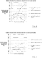
- the volumetric flow rate rose from zero to a particular nominal flow rate according to a step function and then decreased back to zero after an interval of a particular duration or did not decrease at all (interval duration indicated as "cont" on the x-axis).
- the flow rate developed to show some overshoot, akin to the response of a second order system to a step function.
- the nominal flow rate was confirmed using scales supporting a vessel in which the water was collected. It can be seen that the volumetric flow rate as determined on the basis of the frequency of revolution of the rotor deviated more in case of the nozzle with a diameter of 3 mm than in case of the nozzle with a diameter of 1.5 mm.
- FIG. 6 Another property of the type of flow meter 16 shown in Figs. 2 and 3 is that the deviation varies strongly between different meters of the same type and with nozzles of the same diameter. This is illustrated in Fig. 6 for three flow meters. At small flow rates, the variance relative to the mean flow rate determined by the three flow meters is relatively large.
- the data processing device 17 makes use of a method as illustrated in Fig. 7 to determine the total volume of water treated from a point of time corresponding to initial placement of the replaceable liquid treatment cartridge 4 in the water treatment device 1.
- the flow of liquid to the appliance 2, and thus through the flow meter 16, is intermittent.
- the data processing device 17 therefore receives pulse sequences of finite duration. It determines the volume of liquid to which each pulse sequence corresponds and then provides the value of this volume as output. The value is, for example, used as the input to a routine for keeping track of a running total representing the total volume of water treated from a point of time corresponding to initial placement of the replaceable liquid treatment cartridge 4 in the water treatment device 1.
- the data processing device 17 is configured to maintain a pulse count N in memory (not shown separately), and to keep track of the length of a time interval ⁇ t corresponding to a length of a pulse sequence of finite length. In a first step 31, these variables are set to zero. When a pulse is detected, the pulse count N is increased (step 32) by one and a timer for tracking the length of the pulse sequence is triggered (step 33).
- an increment ⁇ t i in the time interval ⁇ t from the preceding pulse to the current pulse is determined (step 34). If the time interval increment ⁇ t i is equal to or smaller than a certain threshold value w , then the increment ⁇ t i is added to the time interval ⁇ t (step 35) and the pulse count N is increased (step 36) by one.
- the method proceeds to a determination of whether a true pulse sequence has been finished. To this end, it is determined whether the number N of pulses exceeds a certain minimum value x .
- the minimum value may be one or higher, but will generally be below ten. The point of this determination is to distinguish spurious pulses arising from interference, vibrations and the like from short sequences corresponding to the flow of a small quantity of water to the appliance 2.
- step 38 the method proceeds to a determination (step 38) of the volume V that has given rise to the pulse sequence, as calculated on the basis of the pulse count N .
- This step 38 entails division of the pulse count N by a pre-set conversion factor representative of the number of pulses per unit volume. Alternatively, multiplication by the inverse of such a factor is carried out.
- the result is further multiplied by a factor representative of the proportion of water (as a fraction of the water passing through the water treatment device 1) that has flowed through the first conduit 9 or second conduit 10, respectively.
- the calculated volume V determined in the preceding step 38 on the basis of the pulse count N is provided as output for use in other data processing steps (not shown).
- This output will also have a relatively large error due to the fact that the diameter of the nozzle 24 is too large, but the error will generally be smaller than 50 %.
- the method Having provided an output for the latest detected pulse sequence of finite length, the method returns to an initial state via the very first step 31, so that the data processing device 17 is ready to determine the volume of liquid giving rise to the next detected pulse sequence.
- This determination again provides a pre-set value as output for frequencies corresponding to volumetric flow rates below a certain value, e.g. 0.1 l ⁇ min -1 .
- a value based on the pulse count is provided for frequencies in a range corresponding to volumetric flow rate in the range of 0.1 l ⁇ min -1 - 2 l ⁇ min -1 .
Landscapes
- Physics & Mathematics (AREA)
- Fluid Mechanics (AREA)
- General Physics & Mathematics (AREA)
- Electromagnetism (AREA)
- Apparatus For Making Beverages (AREA)
Claims (15)
- Procédé pour déterminer un volume de liquide s'écoulant à travers un conduit (9, 10, 15), comprenant :recevoir un signal provenant d'un débitmètre (16) comprenant un rotor (22) apte à être entraîné par du liquide s'écoulant à travers le débitmètre (16), le signal représentant des impulsions pouvant être obtenues par détection de passage d'au moins un dispositif de signalisation (26) dont un mouvement est au moins synchronisé avec celui du rotor (22) ;déterminer un nombre (N) des impulsions dans un intervalle de temps (Δt) ;déterminer une mesure (f) d'une fréquence d'impulsions dans l'intervalle de temps (Δt) ; etdéterminer le volume en fonction d'un nombre (N) d'impulsions dans l'intervalle de temps (Δt) si la mesure (f) indique une fréquence d'impulsions supérieure à une certaine valeur (y), caractérisé pardéterminer le volume comme valeur prédéterminée (z) lorsqu'il est déterminé que la mesure (f) indique une fréquence d'impulsions inférieure ou égale à la certaine valeur (y).
- Procédé selon la revendication 1,
comprenant identifier des moments de début et de fin de l'intervalle de temps (Δt) par détection du début et de l'arrêt de l'écoulement de liquide à travers le conduit. - Procédé selon la revendication 2,
dans lequel les moments de début et de fin de l'intervalle de temps (Δt) sont identifiés par comparaison d'un temps entre des impulsions successives avec une certaine valeur de seuil. - Procédé selon l'une quelconque des revendications 2 et 3,
dans lequel le volume est déterminé comme valeur prédéterminée (z) si la mesure (f) indique une fréquence d'impulsions inférieure ou égale à la certaine valeur (y), mais seulement si le nombre (N) d'impulsions dépasse une certaine valeur minimale. - Procédé selon l'une quelconque des revendications 2 à 4,
dans lequel le volume est déterminé comme valeur prédéterminée (z) si la mesure (f) indique une fréquence d'impulsions inférieure ou égale à la certaine valeur (y), mais seulement si le volume (V) calculé en fonction du nombre d'impulsions dans l'intervalle de temps (Δt) a une valeur inférieure à une certaine valeur maximale, par exemple une certaine valeur maximale correspondant à la valeur prédéterminée (z) du volume. - Procédé selon l'une quelconque des revendications précédentes,
dans lequel le volume de liquide s'écoulant à travers le conduit (9, 10, 15) vers un appareil (2) comprenant au moins un dispositif pour distribuer une boisson, par exemple une boisson chaude, est déterminé. - Procédé selon l'une quelconque des revendications précédentes,
dans lequel le volume de liquide s'écoulant depuis une alimentation en eau du réseau est déterminé. - Procédé selon l'une quelconque des revendications précédentes,
dans lequel le débitmètre (16) comprend un débitmètre à aubes à jet. - Système pour déterminer un volume de liquide s'écoulant à travers un conduit (9, 10, 15), comprenant :une interface pour recevoir un signal provenant d'un débitmètre (16) comprenant un rotor (22) apte à être entraîné par le liquide, le signal représentant des impulsions pouvant être obtenues par détection de passage d'au moins un dispositif de signalisation (26) dont un mouvement est au moins synchronisé avec celui du rotor (22) ;une unité de traitement de signal (17) pour traiter le signal, l'unité de traitement de signal (17) étant configurée :pour déterminer un nombre (N) des impulsions dans un intervalle de temps (Δt) ;pour déterminer une mesure (f) d'une fréquence d'impulsions dans l'intervalle de temps ; etpour déterminer le volume en fonction d'un nombre (N) d'impulsions dans l'intervalle de temps (Δt) si la mesure (f) indique une fréquence d'impulsions supérieure à une certaine valeur (y), caractérisé par le fait quel'unité de traitement de signal (17) est configurée pour déterminer le volume comme valeur prédéterminée (z) lorsqu'il est déterminé que la mesure (f) indique une fréquence d'impulsions inférieure ou égale à la certaine valeur (y).
- Système selon la revendication 9,
configuré pour réaliser un procédé selon l'une quelconque des revendications 1 à 8. - Appareil comprenant :un débitmètre (16),le débitmètre (16) comprenantun rotor (22) apte à être entraîné par un liquide passant à travers le débitmètre (16),au moins un dispositif de signalisation (26) dont un mouvement est au moins synchronisé avec celui du rotor (22), etau moins un capteur pour détecter le passage d'au moins un parmi l'au moins un dispositif de signalisation (26) et générer un signal représentant une séquence d'impulsions, chaque passage détecté résultant en au moins une impulsion ; etun système (3, 17) selon l'une quelconque des revendications 9 et 10 pour traiter le signal.
- Appareil selon la revendication 11,
comprenant en outre un appareil (2) pour distribuer une boisson, par exemple une boisson chaude. - Appareil selon la revendication 11 ou 12,
comprenant en outre un dispositif de traitement de liquide (1) comprenant une cartouche de traitement de liquide remplaçable (4). - Appareil selon l'une quelconque des revendications 11 à 13,
dans lequel le système est configuré pour réaliser la détermination de volume de manière répétée et ajouter chaque volume déterminé à un total cumulé, comprenant en outre un dispositif (18) pour fournir un signal de sortie lorsque le total cumulé a atteint un volume total maximal. - Programme d'ordinateur comprenant un ensemble d'instructions capables, lorsqu'incorporées dans un support lisible par machine, d'amener un système (3) ayant une capacité de traitement d'informations à exécuter un procédé selon l'une quelconque des revendications 1 à 8.
Priority Applications (1)
| Application Number | Priority Date | Filing Date | Title |
|---|---|---|---|
| EP14171535.9A EP2952859B1 (fr) | 2014-06-06 | 2014-06-06 | Procédé et système pour déterminer un volume de liquide s'écoulant à travers un conduit |
Applications Claiming Priority (1)
| Application Number | Priority Date | Filing Date | Title |
|---|---|---|---|
| EP14171535.9A EP2952859B1 (fr) | 2014-06-06 | 2014-06-06 | Procédé et système pour déterminer un volume de liquide s'écoulant à travers un conduit |
Publications (2)
| Publication Number | Publication Date |
|---|---|
| EP2952859A1 EP2952859A1 (fr) | 2015-12-09 |
| EP2952859B1 true EP2952859B1 (fr) | 2019-08-28 |
Family
ID=50884780
Family Applications (1)
| Application Number | Title | Priority Date | Filing Date |
|---|---|---|---|
| EP14171535.9A Active EP2952859B1 (fr) | 2014-06-06 | 2014-06-06 | Procédé et système pour déterminer un volume de liquide s'écoulant à travers un conduit |
Country Status (1)
| Country | Link |
|---|---|
| EP (1) | EP2952859B1 (fr) |
Cited By (2)
| Publication number | Priority date | Publication date | Assignee | Title |
|---|---|---|---|---|
| US12005408B1 (en) | 2023-04-14 | 2024-06-11 | Sharkninja Operating Llc | Mixing funnel |
| US12616945B2 (en) | 2024-05-29 | 2026-05-05 | Sharkninja Operating Llc | Mixing funnel |
Families Citing this family (2)
| Publication number | Priority date | Publication date | Assignee | Title |
|---|---|---|---|---|
| US10703656B2 (en) * | 2016-05-11 | 2020-07-07 | Pentair Filtration Solutions, Llc | Water ionization system and method |
| TWI817519B (zh) * | 2022-05-24 | 2023-10-01 | 桓達科技股份有限公司 | 轉動式流量計於低流速狀態的流量推估方法 |
Family Cites Families (6)
| Publication number | Priority date | Publication date | Assignee | Title |
|---|---|---|---|---|
| US5574229A (en) * | 1994-03-21 | 1996-11-12 | Contadores De Aqua De Zaragoza | Electronic water meter with corrections for flow rate |
| US20060115570A1 (en) * | 2004-11-30 | 2006-06-01 | Guerrero Arturo F | Beverage dispenser with variable-concentration additive dispensing |
| IL173321A0 (en) | 2006-01-24 | 2006-06-11 | Ilan Paz | Fluid flow meter |
| EP1983310A1 (fr) * | 2007-04-20 | 2008-10-22 | Electrolux Home Products Corporation N.V. | Débitmètre à turbine |
| DE102008001635A1 (de) | 2008-02-14 | 2009-08-27 | Brita Gmbh | Verschneideventil und Vorrichtung zur Behandlung von Flüssigkeiten |
| JP2014051290A (ja) * | 2012-09-05 | 2014-03-20 | Hayakawa Sanki Kk | 飲料ディスペンサーの希釈比率調整装置及び方法 |
-
2014
- 2014-06-06 EP EP14171535.9A patent/EP2952859B1/fr active Active
Non-Patent Citations (1)
| Title |
|---|
| None * |
Cited By (2)
| Publication number | Priority date | Publication date | Assignee | Title |
|---|---|---|---|---|
| US12005408B1 (en) | 2023-04-14 | 2024-06-11 | Sharkninja Operating Llc | Mixing funnel |
| US12616945B2 (en) | 2024-05-29 | 2026-05-05 | Sharkninja Operating Llc | Mixing funnel |
Also Published As
| Publication number | Publication date |
|---|---|
| EP2952859A1 (fr) | 2015-12-09 |
Similar Documents
| Publication | Publication Date | Title |
|---|---|---|
| KR102757861B1 (ko) | 커피 분쇄기 제어 방법 | |
| CN110740667B (zh) | 带有传感器的咖啡机 | |
| CN102307505B (zh) | 带有用于检测机器中咖啡量的传感器的自动咖啡机 | |
| US8181565B2 (en) | Method for measuring the quantity of coffee dispensed by a coffee mill and appliance comprising such a mill | |
| EP2952859B1 (fr) | Procédé et système pour déterminer un volume de liquide s'écoulant à travers un conduit | |
| CN101355898B (zh) | 咖啡机的自动剂量控制 | |
| US20080163896A1 (en) | Device for preparation and dispensing of beverages, with cleaning device | |
| CN101478903B (zh) | 在磨碎装置中探测粒料的量的方法 | |
| EP2870472B1 (fr) | Procédé et dispositif pour la détermination de la dureté temporaire de l'eau | |
| EP2943101A1 (fr) | Procédé de fonctionnement d'un broyeur | |
| CN101374443A (zh) | 用于泵控制的方法和装置 | |
| CN112888345B (zh) | 饮料制备机 | |
| AU2019370930A1 (en) | Active system for monitoring and filtering the water for an espresso coffee machine and associated espresso coffee machine | |
| AU2016340808B2 (en) | Dynamic calibration compensation for flow meter | |
| CN114828705B (zh) | 流递送系统 | |
| JP7576682B2 (ja) | 飲料製造器ならびに飲料製造器によって産出されるおよび/または飲料調製のために飲料製造器において使用される温水量を決定するための方法 | |
| US20160302614A1 (en) | Drinks preparation machine and a method for operating a drinks preparation machine | |
| CN109328021B (zh) | 咖啡机 | |
| EP3324809B1 (fr) | Procédé de dosage à auto-étalonnage | |
| US12514394B2 (en) | Zero retention coffee bean hopper | |
| KR101947999B1 (ko) | 얼음추출량 감지 장치 및 이를 구비한 얼음정수기 | |
| CA3002802C (fr) | Compensation d'etalonnage dynamique pour debitmetre | |
| EP2781983A1 (fr) | Procédé et système pour commander un appareil de traitement de fluide | |
| RU2797488C2 (ru) | Машина по приготовлению напитков | |
| CN120981183A (zh) | 饮料机和方法 |
Legal Events
| Date | Code | Title | Description |
|---|---|---|---|
| PUAI | Public reference made under article 153(3) epc to a published international application that has entered the european phase |
Free format text: ORIGINAL CODE: 0009012 |
|
| AK | Designated contracting states |
Kind code of ref document: A1 Designated state(s): AL AT BE BG CH CY CZ DE DK EE ES FI FR GB GR HR HU IE IS IT LI LT LU LV MC MK MT NL NO PL PT RO RS SE SI SK SM TR |
|
| AX | Request for extension of the european patent |
Extension state: BA ME |
|
| 17P | Request for examination filed |
Effective date: 20160427 |
|
| RBV | Designated contracting states (corrected) |
Designated state(s): AL AT BE BG CH CY CZ DE DK EE ES FI FR GB GR HR HU IE IS IT LI LT LU LV MC MK MT NL NO PL PT RO RS SE SI SK SM TR |
|
| GRAP | Despatch of communication of intention to grant a patent |
Free format text: ORIGINAL CODE: EPIDOSNIGR1 |
|
| RIC1 | Information provided on ipc code assigned before grant |
Ipc: G01F 3/00 20060101AFI20190221BHEP Ipc: G01F 15/07 20060101ALN20190221BHEP Ipc: G01F 1/06 20060101ALI20190221BHEP Ipc: G01F 1/075 20060101ALI20190221BHEP |
|
| STAA | Information on the status of an ep patent application or granted ep patent |
Free format text: STATUS: GRANT OF PATENT IS INTENDED |
|
| INTG | Intention to grant announced |
Effective date: 20190328 |
|
| GRAS | Grant fee paid |
Free format text: ORIGINAL CODE: EPIDOSNIGR3 |
|
| GRAA | (expected) grant |
Free format text: ORIGINAL CODE: 0009210 |
|
| STAA | Information on the status of an ep patent application or granted ep patent |
Free format text: STATUS: THE PATENT HAS BEEN GRANTED |
|
| AK | Designated contracting states |
Kind code of ref document: B1 Designated state(s): AL AT BE BG CH CY CZ DE DK EE ES FI FR GB GR HR HU IE IS IT LI LT LU LV MC MK MT NL NO PL PT RO RS SE SI SK SM TR |
|
| REG | Reference to a national code |
Ref country code: GB Ref legal event code: FG4D |
|
| REG | Reference to a national code |
Ref country code: CH Ref legal event code: EP |
|
| REG | Reference to a national code |
Ref country code: AT Ref legal event code: REF Ref document number: 1172976 Country of ref document: AT Kind code of ref document: T Effective date: 20190915 |
|
| REG | Reference to a national code |
Ref country code: IE Ref legal event code: FG4D |
|
| REG | Reference to a national code |
Ref country code: DE Ref legal event code: R096 Ref document number: 602014052411 Country of ref document: DE |
|
| REG | Reference to a national code |
Ref country code: NL Ref legal event code: MP Effective date: 20190828 |
|
| REG | Reference to a national code |
Ref country code: LT Ref legal event code: MG4D |
|
| PG25 | Lapsed in a contracting state [announced via postgrant information from national office to epo] |
Ref country code: LT Free format text: LAPSE BECAUSE OF FAILURE TO SUBMIT A TRANSLATION OF THE DESCRIPTION OR TO PAY THE FEE WITHIN THE PRESCRIBED TIME-LIMIT Effective date: 20190828 Ref country code: SE Free format text: LAPSE BECAUSE OF FAILURE TO SUBMIT A TRANSLATION OF THE DESCRIPTION OR TO PAY THE FEE WITHIN THE PRESCRIBED TIME-LIMIT Effective date: 20190828 Ref country code: NL Free format text: LAPSE BECAUSE OF FAILURE TO SUBMIT A TRANSLATION OF THE DESCRIPTION OR TO PAY THE FEE WITHIN THE PRESCRIBED TIME-LIMIT Effective date: 20190828 Ref country code: BG Free format text: LAPSE BECAUSE OF FAILURE TO SUBMIT A TRANSLATION OF THE DESCRIPTION OR TO PAY THE FEE WITHIN THE PRESCRIBED TIME-LIMIT Effective date: 20191128 Ref country code: HR Free format text: LAPSE BECAUSE OF FAILURE TO SUBMIT A TRANSLATION OF THE DESCRIPTION OR TO PAY THE FEE WITHIN THE PRESCRIBED TIME-LIMIT Effective date: 20190828 Ref country code: NO Free format text: LAPSE BECAUSE OF FAILURE TO SUBMIT A TRANSLATION OF THE DESCRIPTION OR TO PAY THE FEE WITHIN THE PRESCRIBED TIME-LIMIT Effective date: 20191128 Ref country code: PT Free format text: LAPSE BECAUSE OF FAILURE TO SUBMIT A TRANSLATION OF THE DESCRIPTION OR TO PAY THE FEE WITHIN THE PRESCRIBED TIME-LIMIT Effective date: 20191230 Ref country code: FI Free format text: LAPSE BECAUSE OF FAILURE TO SUBMIT A TRANSLATION OF THE DESCRIPTION OR TO PAY THE FEE WITHIN THE PRESCRIBED TIME-LIMIT Effective date: 20190828 |
|
| PG25 | Lapsed in a contracting state [announced via postgrant information from national office to epo] |
Ref country code: IS Free format text: LAPSE BECAUSE OF FAILURE TO SUBMIT A TRANSLATION OF THE DESCRIPTION OR TO PAY THE FEE WITHIN THE PRESCRIBED TIME-LIMIT Effective date: 20191228 Ref country code: LV Free format text: LAPSE BECAUSE OF FAILURE TO SUBMIT A TRANSLATION OF THE DESCRIPTION OR TO PAY THE FEE WITHIN THE PRESCRIBED TIME-LIMIT Effective date: 20190828 Ref country code: ES Free format text: LAPSE BECAUSE OF FAILURE TO SUBMIT A TRANSLATION OF THE DESCRIPTION OR TO PAY THE FEE WITHIN THE PRESCRIBED TIME-LIMIT Effective date: 20190828 Ref country code: RS Free format text: LAPSE BECAUSE OF FAILURE TO SUBMIT A TRANSLATION OF THE DESCRIPTION OR TO PAY THE FEE WITHIN THE PRESCRIBED TIME-LIMIT Effective date: 20190828 Ref country code: GR Free format text: LAPSE BECAUSE OF FAILURE TO SUBMIT A TRANSLATION OF THE DESCRIPTION OR TO PAY THE FEE WITHIN THE PRESCRIBED TIME-LIMIT Effective date: 20191129 Ref country code: AL Free format text: LAPSE BECAUSE OF FAILURE TO SUBMIT A TRANSLATION OF THE DESCRIPTION OR TO PAY THE FEE WITHIN THE PRESCRIBED TIME-LIMIT Effective date: 20190828 |
|
| REG | Reference to a national code |
Ref country code: AT Ref legal event code: MK05 Ref document number: 1172976 Country of ref document: AT Kind code of ref document: T Effective date: 20190828 |
|
| PG25 | Lapsed in a contracting state [announced via postgrant information from national office to epo] |
Ref country code: TR Free format text: LAPSE BECAUSE OF FAILURE TO SUBMIT A TRANSLATION OF THE DESCRIPTION OR TO PAY THE FEE WITHIN THE PRESCRIBED TIME-LIMIT Effective date: 20190828 |
|
| PG25 | Lapsed in a contracting state [announced via postgrant information from national office to epo] |
Ref country code: RO Free format text: LAPSE BECAUSE OF FAILURE TO SUBMIT A TRANSLATION OF THE DESCRIPTION OR TO PAY THE FEE WITHIN THE PRESCRIBED TIME-LIMIT Effective date: 20190828 Ref country code: DK Free format text: LAPSE BECAUSE OF FAILURE TO SUBMIT A TRANSLATION OF THE DESCRIPTION OR TO PAY THE FEE WITHIN THE PRESCRIBED TIME-LIMIT Effective date: 20190828 Ref country code: EE Free format text: LAPSE BECAUSE OF FAILURE TO SUBMIT A TRANSLATION OF THE DESCRIPTION OR TO PAY THE FEE WITHIN THE PRESCRIBED TIME-LIMIT Effective date: 20190828 Ref country code: AT Free format text: LAPSE BECAUSE OF FAILURE TO SUBMIT A TRANSLATION OF THE DESCRIPTION OR TO PAY THE FEE WITHIN THE PRESCRIBED TIME-LIMIT Effective date: 20190828 Ref country code: PL Free format text: LAPSE BECAUSE OF FAILURE TO SUBMIT A TRANSLATION OF THE DESCRIPTION OR TO PAY THE FEE WITHIN THE PRESCRIBED TIME-LIMIT Effective date: 20190828 |
|
| PG25 | Lapsed in a contracting state [announced via postgrant information from national office to epo] |
Ref country code: CZ Free format text: LAPSE BECAUSE OF FAILURE TO SUBMIT A TRANSLATION OF THE DESCRIPTION OR TO PAY THE FEE WITHIN THE PRESCRIBED TIME-LIMIT Effective date: 20190828 Ref country code: SK Free format text: LAPSE BECAUSE OF FAILURE TO SUBMIT A TRANSLATION OF THE DESCRIPTION OR TO PAY THE FEE WITHIN THE PRESCRIBED TIME-LIMIT Effective date: 20190828 Ref country code: IS Free format text: LAPSE BECAUSE OF FAILURE TO SUBMIT A TRANSLATION OF THE DESCRIPTION OR TO PAY THE FEE WITHIN THE PRESCRIBED TIME-LIMIT Effective date: 20200224 Ref country code: SM Free format text: LAPSE BECAUSE OF FAILURE TO SUBMIT A TRANSLATION OF THE DESCRIPTION OR TO PAY THE FEE WITHIN THE PRESCRIBED TIME-LIMIT Effective date: 20190828 |
|
| REG | Reference to a national code |
Ref country code: DE Ref legal event code: R097 Ref document number: 602014052411 Country of ref document: DE |
|
| PLBE | No opposition filed within time limit |
Free format text: ORIGINAL CODE: 0009261 |
|
| STAA | Information on the status of an ep patent application or granted ep patent |
Free format text: STATUS: NO OPPOSITION FILED WITHIN TIME LIMIT |
|
| PG2D | Information on lapse in contracting state deleted |
Ref country code: IS |
|
| 26N | No opposition filed |
Effective date: 20200603 |
|
| PG25 | Lapsed in a contracting state [announced via postgrant information from national office to epo] |
Ref country code: SI Free format text: LAPSE BECAUSE OF FAILURE TO SUBMIT A TRANSLATION OF THE DESCRIPTION OR TO PAY THE FEE WITHIN THE PRESCRIBED TIME-LIMIT Effective date: 20190828 |
|
| PG25 | Lapsed in a contracting state [announced via postgrant information from national office to epo] |
Ref country code: MC Free format text: LAPSE BECAUSE OF FAILURE TO SUBMIT A TRANSLATION OF THE DESCRIPTION OR TO PAY THE FEE WITHIN THE PRESCRIBED TIME-LIMIT Effective date: 20190828 |
|
| PG25 | Lapsed in a contracting state [announced via postgrant information from national office to epo] |
Ref country code: LU Free format text: LAPSE BECAUSE OF NON-PAYMENT OF DUE FEES Effective date: 20200606 |
|
| REG | Reference to a national code |
Ref country code: BE Ref legal event code: MM Effective date: 20200630 |
|
| PG25 | Lapsed in a contracting state [announced via postgrant information from national office to epo] |
Ref country code: IE Free format text: LAPSE BECAUSE OF NON-PAYMENT OF DUE FEES Effective date: 20200606 |
|
| PG25 | Lapsed in a contracting state [announced via postgrant information from national office to epo] |
Ref country code: BE Free format text: LAPSE BECAUSE OF NON-PAYMENT OF DUE FEES Effective date: 20200630 |
|
| PG25 | Lapsed in a contracting state [announced via postgrant information from national office to epo] |
Ref country code: MT Free format text: LAPSE BECAUSE OF FAILURE TO SUBMIT A TRANSLATION OF THE DESCRIPTION OR TO PAY THE FEE WITHIN THE PRESCRIBED TIME-LIMIT Effective date: 20190828 Ref country code: CY Free format text: LAPSE BECAUSE OF FAILURE TO SUBMIT A TRANSLATION OF THE DESCRIPTION OR TO PAY THE FEE WITHIN THE PRESCRIBED TIME-LIMIT Effective date: 20190828 |
|
| PG25 | Lapsed in a contracting state [announced via postgrant information from national office to epo] |
Ref country code: MK Free format text: LAPSE BECAUSE OF FAILURE TO SUBMIT A TRANSLATION OF THE DESCRIPTION OR TO PAY THE FEE WITHIN THE PRESCRIBED TIME-LIMIT Effective date: 20190828 |
|
| REG | Reference to a national code |
Ref country code: DE Ref legal event code: R081 Ref document number: 602014052411 Country of ref document: DE Owner name: BRITA SE, DE Free format text: FORMER OWNER: BRITA GMBH, 65232 TAUNUSSTEIN, DE |
|
| P01 | Opt-out of the competence of the unified patent court (upc) registered |
Effective date: 20230527 |
|
| PGFP | Annual fee paid to national office [announced via postgrant information from national office to epo] |
Ref country code: DE Payment date: 20250429 Year of fee payment: 12 |
|
| PGFP | Annual fee paid to national office [announced via postgrant information from national office to epo] |
Ref country code: GB Payment date: 20250501 Year of fee payment: 12 |
|
| PGFP | Annual fee paid to national office [announced via postgrant information from national office to epo] |
Ref country code: IT Payment date: 20250522 Year of fee payment: 12 |
|
| PGFP | Annual fee paid to national office [announced via postgrant information from national office to epo] |
Ref country code: FR Payment date: 20250508 Year of fee payment: 12 |
|
| PGFP | Annual fee paid to national office [announced via postgrant information from national office to epo] |
Ref country code: CH Payment date: 20250701 Year of fee payment: 12 |