EP2952871B1 - System und verfahren zur messung des reifenlaufflächenprofils - Google Patents
System und verfahren zur messung des reifenlaufflächenprofils Download PDFInfo
- Publication number
- EP2952871B1 EP2952871B1 EP15168265.5A EP15168265A EP2952871B1 EP 2952871 B1 EP2952871 B1 EP 2952871B1 EP 15168265 A EP15168265 A EP 15168265A EP 2952871 B1 EP2952871 B1 EP 2952871B1
- Authority
- EP
- European Patent Office
- Prior art keywords
- tire
- laser distance
- distance measuring
- measuring devices
- temperature
- Prior art date
- Legal status (The legal status is an assumption and is not a legal conclusion. Google has not performed a legal analysis and makes no representation as to the accuracy of the status listed.)
- Active
Links
Images



Classifications
-
- G—PHYSICS
- G01—MEASURING; TESTING
- G01M—TESTING STATIC OR DYNAMIC BALANCE OF MACHINES OR STRUCTURES; TESTING OF STRUCTURES OR APPARATUS, NOT OTHERWISE PROVIDED FOR
- G01M17/00—Testing of vehicles
- G01M17/007—Wheeled or endless-tracked vehicles
- G01M17/02—Tyres
- G01M17/027—Tyres using light, e.g. infrared, ultraviolet or holographic techniques
Definitions
- the present invention relates to a system and method for measuring a tire tread profile where a plurality of laser distance measuring devices are simultaneously used to measure a tread profile of a tire.
- a tool for measuring a radius of curvature of a tire tread surface wherein the tool has three probes for contacting the tread surface to mechanically obtain relative positions of three points on the tread surface in order to find a radius of a circle passing the three point as the radius of curvature.
- a laser distance meter instead of such tool for mechanically obtaining positions of three points on a tread surface, the use of laser distance meters is conceivable as a noncontact measuring device.
- a laser distance meter usually has a strong temperature dependency and output data about the measured distance varies wide depending on the temperature around the laser distance meter.
- a plurality of laser distance meters are simultaneously used, there is a tendency that, due to the variations of output data of the respective laser distance meters, large errors are involved in the differences among the measured distances. This reduces the accuracy of the radius of curvature computed therefrom.
- US 5,636,026 discloses a system for measuring a profile of the tread portion of a tire comprising a laser distance measuring device oriented toward the tread portion of the tire in order to measure the distance to the tread portion, with an insulating wall enclosing the laser distance measuring device and provided with an aperture through which the laser beam of the laser distance measuring device can pass.
- WO 2012/074527 discloses a system for measuring a tread profile of a tire comprising a tire holding device for supporting the tire rotatably around the tire rotational axis and a plurality of laser distance measuring devices arranged along the axial direction of the tire and oriented toward the tread portion of the tire.
- an object of the present invention to provide a system and method for measuring a tread profile of a tire, in which data about a tread profile e.g. a tread radius of curvature can be measured accurately without being affected by a temperature dependency of a laser distance measuring device.
- a system for measuring a tread profile of a tire comprises a tire holding device comprising a tire support shaft for supporting the tire rotatably around the tire rotational axis, a plurality of laser distance measuring devices arranged along the axial direction of the tire and oriented toward the tread portion of the tire in order to measure distances to the tread portion, an insulating wall enclosing the laser distance measuring devices, wherein the insulating wall is provided with an aperture through which laser beams of the laser distance measuring devices can pass, and a shutter configured to close the aperture, and a temperature controller for controlling the temperature of a gas surrounding the laser distance measuring devices in the insulating wall wherein the temperature controller includes a cooling system and is configured to continuously supply temperature controlled air to the interior of the insulating wall when the aperture is uncovered by taking off the shutter.
- a method according to the present invention for measuring a tread profile of a tire utilizes the above-mentioned system for measuring a tread profile of a tire, and comprises a process for keeping the temperature of the gas surrounding the laser distance measuring devices in the insulating wall at a substantially constant temperature by the use of the temperature controller so as to reduce variations of data output from the laser distance measuring devices due to variations of the temperature of the laser distance measuring devices.
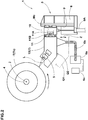
- a system 1 for measuring a tread profile of a tire T comprises a tire holding device 2, and a laser measuring apparatus 3.
- the tire T as an object to be measured is a pneumatic tire, for example, a passenger car tire provided in the tread surface Ts with circumferentially extending ribs R, for example, a center rib Rc, two middle ribs Rm, and two axially outermost shoulder ribs Rs.
- a pneumatic tire for example, a passenger car tire provided in the tread surface Ts with circumferentially extending ribs R, for example, a center rib Rc, two middle ribs Rm, and two axially outermost shoulder ribs Rs.
- the tire holding device 2 comprises, as shown in Fig.1 , a tire support shaft 4 for supporting the tire T rotatably around the tire rotational axis j.
- the tire T which is mounted on a rim is horizontally supported by the tire support shaft 4.
- the system 1 for measuring a tread profile such that the tire support shaft 4 supports the tire T vertically.
- the tire holding device 2 further comprises a drive unit (not shown) for rotating the tire support shaft 4 at a predetermined rotational speed which comprises a motor such as electric motor.
- the laser measuring apparatus 3 comprises:
- the temperature controller 6 comprises an air-conditioning and heating machine 6a, and an air duct 6b for sending the air whose temperature is controlled by the air-conditioning and heating machine 6a toward the laser distance measuring devices 5 in order to keep the air surrounding the laser distance measuring devices 5 within a narrow range, preferably at a predetermined constant temperature.
- a flexible stretchable duct made from accordion-folding material is used an the air duct 6b, for example.
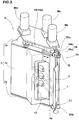
- the laser distance measuring devices 5 and the insulating wall 7 are mounted.
- the insulating wall 7 in this example includes an upper wall 7a above the laser distance measuring devices 5, a lower wall 7c under the laser distance measuring devices 5, and a side wall 7b extending between the upper wall 7a and the lower wall 7c.
- the insulating wall 7 encloses all of the laser distance measuring devices 5.
- the insulating wall 7 is formed from a material or materials having heat insulation property in order to effectively keep the temperature of the interior constant.
- the insulating wall 7 is provided with a aperture 13 through which the laser beams L of the laser distance measuring devices 5 pass, a shutter 14 for closing/opening the aperture 13, and an inlet 15 for taking the air supplied from the temperature controller 6 into the interior.
- the aperture 13 and the inlet 15 are formed in the side wall 7b.
- the above-mentioned air duct 6b is connected through a flared part 6d whose cross sectional area is gradually increased toward the inlet 15 as shown in Fig. 1 in order that the conditioned air is distributed evenly across the inside of the insulating wall 7.
- the shutter 14 is made of, for example, a metal material. Preferably. a sheet of heat insulating material is applied to one side of the shutter 14.
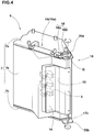
- the shutter 14 is formed from a plate material which is folded to have a Z-shaped cross section as shown in Fig. 3 .
- a shutter opening/closing device 16 for opening/closing the shutter 14 is mounted on the second movable frame 12.
- the shutter opening/closing device 16 comprises a rotatable shaft 17 and an actuator 19 for rotating the rotatable shaft 17.
- both ends of the rotatable shaft 17 are respectively supported by a support piece 20a provided on the upper wall 7a and a support piece 20b provided on the lower wall 7c so that the rotatable shaft 17 extends in the vertical direction along the side wall 7b.
- the shutter 14 is fixed to the rotatable shaft 17 by an appropriate means, for example, rivet, welding, screw, press fitting or the like.
- the actuator 19 in this example is a cylinder 19a having a piston rod.
- the piston rod is connected to the rotatable shaft 17 through a linkage 18.
- the linkage 18 is made up of a link 18a one end of which is fixed to the piston rod of the actuator 19 and a link 18b one end of which is fixed to one end of the rotatable shaft 17, and the other end of the link 18a and the other end of the link 18b are pivotally connected to each other.
- the end of the actuator 19 on the opposite side of the piston rod is pivotally supporting by the upper wall 7a of the insulating wall 7. Therefore, by the extension of the cylinder 19a, the rotatable shaft 17 is rotated through the linkage 18 so that the shutter 14 opens the aperture 13. By the retraction of the cylinder 19a, the rotatable shaft 17 is rotated so that the shutter 14 closes the aperture 13.
- a mechanical linear actuator such as a ball screw in combination with the linkage, a geared motor coupled with the rotatable shaft 17 or the like
- the guide device 9 comprises a guide rail extending straight in the direction Z, and a guide groove slidably fitted with the guide rail.
- the guide device 11 comprises a guide rail extending straight in the direction X, and a guide groove slidably fitted with the guide rail.
- the guide device 9,11 is not limited to this rail-and-groove structure. Any suitable structures may be employed.
- a moving device which comprises a cylinder 9A mounted on the main frame 8 such that its piston rod is capable of extending and retracting in the direction Z, and the piston rod is connected to the first movable frame 10. Therefore, by the extension and retraction of the cylinder 9A, the first movable frame 10 is moved in the direction Z between the waiting position Q1 and the measuring position Q2.
- a moving device which comprises a ball screw shaft 11A ( Fig. 2 ) pivotally supported by the first movable frame 10 so as to extend in the tire axial direction X, a motor Mc for rotating the ball screw shaft 11A, and a ball nut 11B engaging with the ball screw shaft 11A and fixed to the second movable frame 12. Therefore, by rotating the ball screw shaft 11A with the motor MC, the second movable frame 12 is moved in the tire axial direction X
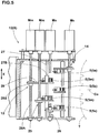
- the laser distance measuring devices 5 are arranged at intervals in the tire axial direction X.
- five laser distance measuring devices 5 are arranged, which are a central laser distance measuring device 5c, two middle laser distance measuring devices 5m one disposed each side thereof, and two outer laser distance measuring devices 5s disposed axially outside the respectively middle laser distance measuring devices 5m.
- the central laser distance measuring device 5c is fixed to the second movable frame 12 and is movable in the tire axial direction X together with the second movable frame 12.
- Each of the middle laser distance measuring devices 5m is supported by the second movable frame 12 through a guide device 25 so that each of the middle laser distance measuring devices 5m is movable in the tire axial direction X relatively to the central laser distance measuring device 5c.
- Each of the outer laser distance measuring devices 5s is supported by the second movable frame 12 through a guide device 26 so that each of the outer laser distance measuring devices 5s is movable in the tire axial direction X relatively to the central laser distance measuring device 5c as well as the middle laser distance measuring devices 5m.
- the guide devices 25 for the respective middle laser distance measuring devices 5m include a single guide shaft 27 in common.
- the guide devices 26 for the respective outer laser distance measuring devices 5s include a single guide shaft 27 in common. Both ends of each guide shaft 27 are respectively fixed to an upper part and lower part of the second movable frame 12 so that the guide shaft 27 extends in the direction X.
- Each of the guide devices 25 and 26 comprises:
- the position of the central laser distance measuring device 5c can be adjusted to a reference position which is for example set on the tire equator Co.
- the positions of the middle laser distance measuring devices 5m and the positions of the outer laser distance measuring devices 5s can be separately adjusted to suitable measuring positions in relation to that of the central laser distance measuring device 5c according to the tire size, the tread pattern and the like.
- the laser distance measuring devices 5 are arranged so that the center axes of the laser beams L from the respective devices 5 are arranged in a line parallel with the tire axial direction X and within a single plane extending radially outwardly from the tire rotational axis j, in other words, a single plane including the tire rotational axis j.
- the laser distance measuring devices 5 it is desirable to use a laser distance measuring device capable of irradiating the laser beam L having a width w of not less than 5 mm as shown in Fig. 6 .
- a laser distance measuring device capable of irradiating the laser beam L having a width w of not less than 5 mm as shown in Fig. 6 .
- a negative effect of a small irregularity 30 of the tread surface Ts (for example, resulted from a sipe 30a, slot 30b or the like) which exists well within the irradiation part La corresponding to the width w of the laser beam L can be removed from the measuring result.
- the irregularity 30 is large, for example, the irregularity 30 is an axial groove 31, and there is a possibility that the entire irradiation part La is included in the groove 31, the measuring result becomes noise data or invalid data. Such invalid data is removed through the after-mentioned smoothing processing by the use of a computing device.
- a method for measuring a tread profile comprises a temperature controlling process SA and a measuring process SB.
- the temperature of the inside of the insulating wall 7 enclosing the laser distance measuring devices 5 is controlled by the use of the temperature controller 6 so that the temperature of the gas or air around the laser distance measuring devices 5 is kept substantially constant in order to reduce variations of output data of the laser distance measuring devices 5 and accurately measure the tread profile.
- the temperature controlling process SA comprises: closing the aperture 13 of the insulating wall 7 with the shutter 14; and uncovering the aperture 13 by taking off the shutter 14.
- the actuator 19 By activating the actuator 19, in this embodiment, by retracting the rod of the cylinder 19a, the linkage 18 rotates the rotatable shaft 17 together with the shutter 14 and the aperture 13 is closed. Further, by extending the rod of the cylinder 19a, the rotatable shaft 17 is rotated together with the shutter 14 and the aperture 13 is uncovered.
- the temperature of the air in the interior of the insulating wall 7 is controlled by the temperature controller 6. It is desirable that the temperature is kept within a range between a preset value + 1 degree C and the preset value - 1 degree C in order that the variations of the output data of the laser distance measuring devices 5 due to their temperature dependency can be surely eliminated.
- the preset value for the temperature namely, the target temperature is 22 to 28 degrees C., preferably 24 to 26 degrees C., more preferably 25 degrees C.
- the indoor air existing outside the insulating wall 7 is drawn into the air-conditioning and heating machine 6a of the temperature controller 6, and temperature controlled, and then sent into the interior of the insulating wall 7 through the inlet 15.
- the temperature controller 6 it is also possible to construct the temperature controller 6 as a circulation type such that the air existing in the interior of the insulating wall 7 is drawn into the air-conditioning and heating machine 6a and then the temperature controlled air is returned to the interior of the insulating wall 7.
- the interior of the insulating wall 7 is continuously supplied with the temperature controlled air from the temperature controller 6.
- the tread profile measuring process SB is for determining a tread radius TR.
- the process SB in this embodiment includes: a measuring process SB1 for determining a first tread radius TRs based on the measurements at the tread center (center rib Rc in this example) and two tread shoulder portions (two axially outermost shoulder ribs Rs in this example), and a measuring process SB2 for determining a second tread radius TRm based on the measurements at the tread center and two tread middle portions (two middle ribs Rm in this example).
- the first tread radius TRs is useful for predicting the steering stability in some countries whereas the second tread radius TRm is useful for predicting the steering stability in other countries.
- it is preferably to measure the first and second tread radii TRs and TRm.
- Each tread profile measuring process SB, SB1, SB2 comprises a measuring step, an averaging step, and a computing step.
- a first set of distance data y1 (y11, y12, y13 --- y1m) are obtained from the first laser distance measuring device 5
- a second set of distance data y2 (y21, y22, y23 --- y2m) are obtained from the second laser distance measuring device 5
- a third set of distance data y3 (y31, y32, y33 --- y3m) are obtained from the third laser distance measuring device 5.
- distance data y1 (y11-y1m) from the central laser distance measuring device 5c to the tread center (center rib Rc) are obtained
- distance data y2 (y21-y2m) from one of the outer laser distance measuring devices 5s to the tread shoulder portion (the opposite shoulder rib Rs) are obtained
- distance data y3 (y31-y3m) from the other outer laser distance measuring device 5s to the other tread shoulder portion (the opposite shoulder rib Rs) are obtained.
- a smoothing processing is carried out, which is for removing therefrom the above-mentioned invalid data resulting from large irregularity 30 (such as the axial groove 31 in this example).
- each set of the distance data y1, y2, y3 excluding the invalid data if any, are averaged to obtain an average value y1N, y2N, y3N.
- the number m is, for example, set to be not less than 500.
- a moving average yN[i] of a fixed number k of the previous data yn[i-1] through yn[i-k] is obtained.
- the moving average yN[i] is obtained as (summation of yn[i-1] through yn[i-k])/k.
- yn[i] is removed as invalid data from the set n of the distance data yn.
- the threshold value preferably set is a value more than the expected maximum magnitude of Radial Run Out (RR0) of the tire and less than the depth of the axial groove 31 included in the measuring portion (for example ribs R). For example, a value of about 3.0 mm is set to the threshold value.
- the tread radius TR is obtained as a radius of a circle passing through three points on the tread surface.
- the Y-coordinate values of the three points are given by the above-mentioned three average values y1N, y2N and y3N.
- the X-coordinate values of the three points are given by distances x1, x2 and x3 of the laser distance measuring devices 5 relating to the average values y1N, y2N and y3N, respectively, which are measured in the tire axial direction from a reference position X (reference position X can be arbitrary defined) in the tire axial direction.
- the three points are expressed as P1(x1,y1N), P2(x2,y2N) and P3(x3,y3N).
- the radius of a circle passing through P1(x1,y1N), P2(x2,y2N) and P3(x3,y3N) is computed as the tread radius TR.
- the averaging step including the smoothing processing and the computing step are implemented by the computing device.
- Each tread profile measuring process SB, SB1, SB2 is implemented as explained above. In the case where the measuring process SB1 and the measuring process SB2 are implemented, it is not necessary to implement these processes SB1 and SB2 one after the other. It is possible to implement the processes SB1 and SB2 at the same time. In this case, the data and processing in connection with the central laser distance measuring device 5c can be sheared between the processes SB1 and SB2.
- the aperture 13 is closed so that the air in the interior of the insulating wall 7 is kept at the preset temperature. As described above, during the aperture 13 is uncovered, namely, during measuring the distances, it is desirable that the interior of the insulating wall 7 is supplied with the temperature controlled air from the temperature controller 6.
- the tire T held by the tire holding device 2 is exchanged for the next tire to be measured .
- the number m of the circumferentially different measuring positions corresponding to the number of a set of distance data is not more than 2000. Even if the number m is increased over 2000, the accuracy of the measured tread profile reaches a ceiling whereas the computational time and cost increase. If the number m is less than 500, there is a possibility that the accuracy is decreased, in particular, in the case of a tread pattern including a large number of axial grooves (large irregularity 30).
- the number k of the previous data is at least 2 and preferably at most 100. Even if the number k is increased over 100, the effect of the smoothing processing reaches a ceiling whereas the computational time and cost increase.
- the number of revolutions of the tire T during measuring the radial distances with the laser distance measuring devices 5 is set in a range of from 20 to 3000 rpm for example.
- the width w of the laser beam L is not less than 10 % and not more than 70 % of the width WR of the rib R as the measuring object in order to effectively utilize the above-mentioned filtering function of the laser distance measuring device itself. If the width W of the laser beam L is less than 10 % of the rib width WR or less than 5 mm, it becomes difficult to filter out the irradiation part La such as sipe 30a and cut 30b. If the width w is more than 70 % of the rib width WR, there is a possibility that the laser beam L scans off the edge of the rib R, and the variation of the output data of the laser distance measuring device 5 is increased.
- the method for measuring the tread profile include a calibration process for calibrating the laser distance measuring devices before measuring the tread profile, using a calibration tool 35.
- the calibration tool 35 comprises a cylindrical base part 36 supported by the tire support shaft 4 coaxially therewith and rotatably therearound, and a plurality of reflector plates 37 fixed to the base part 36.
- the reflector plates 37 are arranged around the tire support shaft 4 at intervals as shown in Fig. 8(A) .
- Each reflector plate 37 has a reflecting surface extending along the tire support shaft 4 to cover all of the laser distance measuring devices 5 as shown in Fig. 8(B) .
- the reflecting surfaces of the reflector plates 37 are placed at different radial distances from the axis 4i of the tire support shaft 4 corresponding to the tire rotational axis j.
- Each reflecting surface is preferably formed by a part of the surface of a circular cylinder which is coaxial with the tire support shaft 4 in order to facilitate the position adjustment for the reflector plate 37.
- the reflector plates 37 are a first reflector plate 37a having a reflecting surface at a radial distance F1 from the axis 4i of the tire support shaft 4 corresponding to the tire rotational axis j, a second reflector plate 37b having a reflecting surface at a radial distance F2 larger than the radial distance F1 of the first reflector plate 37a, and a third reflector plate 37c having a reflecting surface at the radial distance F3 smaller than the radial distance F1 of the first reflector plate 37a.
- the first reflector plate 37a is positioned at the measuring position, and by the use of the first reflector plate 37a, the origin of each laser distance measuring device 5 is calibrated. Then, the calibration tool 35 is rotated so that the second and third reflector plates 37b and 37c are alternately positioned at the measuring position, and by the use of the second and third reflector plates 37b and 37c, each laser distance measuring device 5 is calibrated for the observed data.
Landscapes
- Physics & Mathematics (AREA)
- General Physics & Mathematics (AREA)
- Length Measuring Devices By Optical Means (AREA)
- Tires In General (AREA)
Claims (3)
- System (1) zum Messen eines Laufflächenprofils eines Reifens (T), umfassendeine Reifenhaltevorrichtung (2), die eine Reifenlagerwelle (4) zum drehbaren Lagern des Reifens (T) um die Reifendrehachse (j) herum umfasst,eine Mehrzahl von Laserabstandsmessvorrichtungen (5), die entlang der axialen Richtung des Reifens (T) angeordnet und in Richtung des Laufflächenabschnitts des Reifens (T) orientiert sind, um Abstände zu dem Laufflächenabschnitt zu messen,dadurch gekennzeichnet, dass das System ferner eine Isolierwand (7), die die Laserabstandsmessvorrichtungen (5) umschließt,wobei die Isolierwand (7) mit einer Öffnung (13) versehen ist, durch die Laserstrahlen (L) der Laserabstandsmessvorrichtungen (5) hindurchtreten können, und einem Verschluss (14), der ausgestaltet ist, um die Öffnung (13) zu verschließen, undeinen Temperaturcontroller (6) zum Steuern der Temperatur eines die Laserabstandsmessvorrichtungen (5) in der Isolierwand (7) umgebenden Gases umfasst,wobei der Temperaturcontroller (6) ein Kühlsystem umfasst und ausgestaltet ist, um kontinuierlich temperaturgesteuerte Luft dem Inneren der Isolierwand (7) zuzuführen, wenn die Öffnung (13) durch Abnahme des Verschlusses (14) freigelegt ist.
- Verfahren zum Messen eines Laufflächenprofils eines Reifens (T) unter Verwendung des Systems (1) nach Anspruch 1, das ein Halten der Temperatur des die Laserabstandsmessvorrichtungen (5) in der Isolierwand (7) umgebenden Gases auf einer im Wesentlichen konstanten Temperatur unter Verwendung des Temperaturcontrollers (6) umfasst, um Schwankungen von durch die Laserabstandsmessvorrichtungen (5) ausgegebenen Daten aufgrund von Schwankungen der Temperatur der Laserabstandsmessvorrichtungen (5) zu verringern.
- Verfahren zum Messen eines Laufflächenprofils eines Reifens (T) nach Anspruch 2, wobei die im Wesentlichen konstante Temperatur eine vorgegebene Solltemperatur plus/minus 1 Grad C ist.
Applications Claiming Priority (1)
| Application Number | Priority Date | Filing Date | Title |
|---|---|---|---|
| JP2014114282A JP6159294B2 (ja) | 2014-06-02 | 2014-06-02 | タイヤのトレッド形状測定方法、及びそれに用いるトレッド形状測定装置 |
Publications (2)
| Publication Number | Publication Date |
|---|---|
| EP2952871A1 EP2952871A1 (de) | 2015-12-09 |
| EP2952871B1 true EP2952871B1 (de) | 2018-10-10 |
Family
ID=53181162
Family Applications (1)
| Application Number | Title | Priority Date | Filing Date |
|---|---|---|---|
| EP15168265.5A Active EP2952871B1 (de) | 2014-06-02 | 2015-05-19 | System und verfahren zur messung des reifenlaufflächenprofils |
Country Status (3)
| Country | Link |
|---|---|
| EP (1) | EP2952871B1 (de) |
| JP (1) | JP6159294B2 (de) |
| CN (1) | CN105180833B (de) |
Families Citing this family (5)
| Publication number | Priority date | Publication date | Assignee | Title |
|---|---|---|---|---|
| CN106197275B (zh) * | 2016-07-21 | 2019-03-12 | 天津大学 | 影像测量中提取圆柱形盲孔中央任意面孔心坐标的方法 |
| JP7212559B2 (ja) * | 2019-03-18 | 2023-01-25 | 住友重機械工業株式会社 | 形状測定装置及び形状測定方法 |
| CN111238834A (zh) * | 2020-01-20 | 2020-06-05 | 东莞市秉能橡胶有限公司 | 一种轮胎测量方法 |
| CN114264234A (zh) * | 2021-12-24 | 2022-04-01 | 哈尔滨工业大学芜湖机器人产业技术研究院 | 一种非接触式叶轮跳动检测系统和方法 |
| CN116026280B (zh) * | 2023-03-29 | 2023-07-04 | 中策橡胶集团股份有限公司 | 一种轮胎胎侧应力应变自动化检测设备和检测方法 |
Citations (1)
| Publication number | Priority date | Publication date | Assignee | Title |
|---|---|---|---|---|
| WO2012074527A1 (en) * | 2010-12-02 | 2012-06-07 | Michelin Recherche Et Technique, S.A. | Method for prediction and control of tire uniformity parameters from crown thickness variation |
Family Cites Families (10)
| Publication number | Priority date | Publication date | Assignee | Title |
|---|---|---|---|---|
| JPS5943307A (ja) * | 1982-09-03 | 1984-03-10 | Sumitomo Rubber Ind Ltd | タイヤの寸法測定方法及び装置 |
| US5636026A (en) * | 1995-03-16 | 1997-06-03 | International Electronic Machines Corporation | Method and system for contactless measurement of railroad wheel characteristics |
| JP4580221B2 (ja) | 2004-11-26 | 2010-11-10 | 住友ゴム工業株式会社 | トレッドラジアス測定治具 |
| JP2006308320A (ja) * | 2005-04-26 | 2006-11-09 | Sumitomo Rubber Ind Ltd | タイヤ複合測定装置 |
| JP2008116352A (ja) * | 2006-11-06 | 2008-05-22 | Ishikawajima Constr Materials Co Ltd | レーザ式変位計測装置およびそれを用いた寸法変化測定方法 |
| JP2008281438A (ja) * | 2007-05-10 | 2008-11-20 | Bridgestone Corp | 空気入りタイヤの縦振れ測定方法および装置 |
| ES2369002T3 (es) * | 2007-05-23 | 2011-11-24 | Snap-On Equipment Srl A Unico Socio | Procedimiento y aparato para determinar la dimensión geométrica de una rueda de vehículo que comprende sensores ópticos. |
| NL2005570C2 (en) * | 2009-12-31 | 2011-07-04 | Volkerrail Nederland B V | Train with optical measuring implement and method. |
| JP5726045B2 (ja) * | 2011-11-07 | 2015-05-27 | 株式会社神戸製鋼所 | タイヤ形状検査方法、及びタイヤ形状検査装置 |
| JP5837952B2 (ja) * | 2014-03-07 | 2015-12-24 | 住友ゴム工業株式会社 | タイヤのトレッドラジアス測定方法、及びそれに用いるトレッドラジアス測定装置 |
-
2014
- 2014-06-02 JP JP2014114282A patent/JP6159294B2/ja active Active
-
2015
- 2015-04-27 CN CN201510205478.2A patent/CN105180833B/zh active Active
- 2015-05-19 EP EP15168265.5A patent/EP2952871B1/de active Active
Patent Citations (1)
| Publication number | Priority date | Publication date | Assignee | Title |
|---|---|---|---|---|
| WO2012074527A1 (en) * | 2010-12-02 | 2012-06-07 | Michelin Recherche Et Technique, S.A. | Method for prediction and control of tire uniformity parameters from crown thickness variation |
Also Published As
| Publication number | Publication date |
|---|---|
| JP2015227847A (ja) | 2015-12-17 |
| CN105180833B (zh) | 2019-06-14 |
| EP2952871A1 (de) | 2015-12-09 |
| JP6159294B2 (ja) | 2017-07-05 |
| CN105180833A (zh) | 2015-12-23 |
Similar Documents
| Publication | Publication Date | Title |
|---|---|---|
| EP2952871B1 (de) | System und verfahren zur messung des reifenlaufflächenprofils | |
| JP5837952B2 (ja) | タイヤのトレッドラジアス測定方法、及びそれに用いるトレッドラジアス測定装置 | |
| US5789668A (en) | Apparatus and related methods for obtaining tire profiles including the tread and both sidewalls | |
| JP6420639B2 (ja) | トレッド形状測定方法 | |
| EP3093611B1 (de) | Vorrichtung und verfahren zur messung des geradheitsfehlerns von stangen oder rohren | |
| EP2950045B1 (de) | Vorrichtung und verfahren zur detektion einer normale einer gekrümmten fläche und entsprechende verarbeitungsvorrichtung | |
| CN101166950B (zh) | 用于扫描工件表面的方法 | |
| JP2014531602A (ja) | 測定方法 | |
| CA2804309C (en) | Wind tunnel model measuring system and method | |
| CN111536903B (zh) | 一种多个线激光传感器拼接测量轮胎形貌的装置及方法 | |
| CN106767418B (zh) | 一种大型回转体外形扫描测量装置及方法 | |
| CN106152955B (zh) | 一种大尺寸轴类零件检测装置及方法 | |
| JP2008196881A (ja) | タイヤの断面の厚さ分布測定装置、及び、タイヤの断面の厚さ分布測定方法 | |
| CN107438750B (zh) | 用于测量长轮廓的方法和设备 | |
| KR100509915B1 (ko) | 열연강판 형상측정기용 다중교정기 | |
| JPWO2006115203A1 (ja) | タイヤサイド部の外形異常検出方法および装置 | |
| CN209737650U (zh) | 一种工业机器人臂应变检测装置 | |
| CN222188193U (zh) | 缸盖测量设备 | |
| KR200237798Y1 (ko) | 회전식 온도분포 측정기 | |
| JP2975364B1 (ja) | 多角形管の肉厚測定装置および測定方法 | |
| KR20160101768A (ko) | 공기압 타이어의 실내주행 시험장치 및 그 시험측정 방법 | |
| US20110037989A1 (en) | Measurement arrangement with a measurement head in order to carry out inspection measurement | |
| JP4380941B2 (ja) | 検査装置 | |
| CN111344110A (zh) | 用于加工玻璃窗格的方法 | |
| JP2001187407A (ja) | タイヤモールドの検査方法 |
Legal Events
| Date | Code | Title | Description |
|---|---|---|---|
| PUAI | Public reference made under article 153(3) epc to a published international application that has entered the european phase |
Free format text: ORIGINAL CODE: 0009012 |
|
| AK | Designated contracting states |
Kind code of ref document: A1 Designated state(s): AL AT BE BG CH CY CZ DE DK EE ES FI FR GB GR HR HU IE IS IT LI LT LU LV MC MK MT NL NO PL PT RO RS SE SI SK SM TR |
|
| AX | Request for extension of the european patent |
Extension state: BA ME |
|
| 17P | Request for examination filed |
Effective date: 20160608 |
|
| RBV | Designated contracting states (corrected) |
Designated state(s): AL AT BE BG CH CY CZ DE DK EE ES FI FR GB GR HR HU IE IS IT LI LT LU LV MC MK MT NL NO PL PT RO RS SE SI SK SM TR |
|
| GRAP | Despatch of communication of intention to grant a patent |
Free format text: ORIGINAL CODE: EPIDOSNIGR1 |
|
| STAA | Information on the status of an ep patent application or granted ep patent |
Free format text: STATUS: GRANT OF PATENT IS INTENDED |
|
| INTG | Intention to grant announced |
Effective date: 20180502 |
|
| RAP1 | Party data changed (applicant data changed or rights of an application transferred) |
Owner name: SUMITOMO RUBBER INDUSTRIES, LTD. |
|
| GRAS | Grant fee paid |
Free format text: ORIGINAL CODE: EPIDOSNIGR3 |
|
| GRAA | (expected) grant |
Free format text: ORIGINAL CODE: 0009210 |
|
| STAA | Information on the status of an ep patent application or granted ep patent |
Free format text: STATUS: THE PATENT HAS BEEN GRANTED |
|
| AK | Designated contracting states |
Kind code of ref document: B1 Designated state(s): AL AT BE BG CH CY CZ DE DK EE ES FI FR GB GR HR HU IE IS IT LI LT LU LV MC MK MT NL NO PL PT RO RS SE SI SK SM TR |
|
| REG | Reference to a national code |
Ref country code: GB Ref legal event code: FG4D |
|
| REG | Reference to a national code |
Ref country code: CH Ref legal event code: EP Ref country code: AT Ref legal event code: REF Ref document number: 1051808 Country of ref document: AT Kind code of ref document: T Effective date: 20181015 |
|
| REG | Reference to a national code |
Ref country code: IE Ref legal event code: FG4D |
|
| REG | Reference to a national code |
Ref country code: DE Ref legal event code: R096 Ref document number: 602015017720 Country of ref document: DE |
|
| REG | Reference to a national code |
Ref country code: NL Ref legal event code: MP Effective date: 20181010 |
|
| REG | Reference to a national code |
Ref country code: LT Ref legal event code: MG4D |
|
| REG | Reference to a national code |
Ref country code: AT Ref legal event code: MK05 Ref document number: 1051808 Country of ref document: AT Kind code of ref document: T Effective date: 20181010 |
|
| PG25 | Lapsed in a contracting state [announced via postgrant information from national office to epo] |
Ref country code: NL Free format text: LAPSE BECAUSE OF FAILURE TO SUBMIT A TRANSLATION OF THE DESCRIPTION OR TO PAY THE FEE WITHIN THE PRESCRIBED TIME-LIMIT Effective date: 20181010 |
|
| PG25 | Lapsed in a contracting state [announced via postgrant information from national office to epo] |
Ref country code: NO Free format text: LAPSE BECAUSE OF FAILURE TO SUBMIT A TRANSLATION OF THE DESCRIPTION OR TO PAY THE FEE WITHIN THE PRESCRIBED TIME-LIMIT Effective date: 20190110 Ref country code: LT Free format text: LAPSE BECAUSE OF FAILURE TO SUBMIT A TRANSLATION OF THE DESCRIPTION OR TO PAY THE FEE WITHIN THE PRESCRIBED TIME-LIMIT Effective date: 20181010 Ref country code: HR Free format text: LAPSE BECAUSE OF FAILURE TO SUBMIT A TRANSLATION OF THE DESCRIPTION OR TO PAY THE FEE WITHIN THE PRESCRIBED TIME-LIMIT Effective date: 20181010 Ref country code: PL Free format text: LAPSE BECAUSE OF FAILURE TO SUBMIT A TRANSLATION OF THE DESCRIPTION OR TO PAY THE FEE WITHIN THE PRESCRIBED TIME-LIMIT Effective date: 20181010 Ref country code: BG Free format text: LAPSE BECAUSE OF FAILURE TO SUBMIT A TRANSLATION OF THE DESCRIPTION OR TO PAY THE FEE WITHIN THE PRESCRIBED TIME-LIMIT Effective date: 20190110 Ref country code: AT Free format text: LAPSE BECAUSE OF FAILURE TO SUBMIT A TRANSLATION OF THE DESCRIPTION OR TO PAY THE FEE WITHIN THE PRESCRIBED TIME-LIMIT Effective date: 20181010 Ref country code: ES Free format text: LAPSE BECAUSE OF FAILURE TO SUBMIT A TRANSLATION OF THE DESCRIPTION OR TO PAY THE FEE WITHIN THE PRESCRIBED TIME-LIMIT Effective date: 20181010 Ref country code: IS Free format text: LAPSE BECAUSE OF FAILURE TO SUBMIT A TRANSLATION OF THE DESCRIPTION OR TO PAY THE FEE WITHIN THE PRESCRIBED TIME-LIMIT Effective date: 20190210 Ref country code: LV Free format text: LAPSE BECAUSE OF FAILURE TO SUBMIT A TRANSLATION OF THE DESCRIPTION OR TO PAY THE FEE WITHIN THE PRESCRIBED TIME-LIMIT Effective date: 20181010 Ref country code: FI Free format text: LAPSE BECAUSE OF FAILURE TO SUBMIT A TRANSLATION OF THE DESCRIPTION OR TO PAY THE FEE WITHIN THE PRESCRIBED TIME-LIMIT Effective date: 20181010 |
|
| PG25 | Lapsed in a contracting state [announced via postgrant information from national office to epo] |
Ref country code: AL Free format text: LAPSE BECAUSE OF FAILURE TO SUBMIT A TRANSLATION OF THE DESCRIPTION OR TO PAY THE FEE WITHIN THE PRESCRIBED TIME-LIMIT Effective date: 20181010 Ref country code: SE Free format text: LAPSE BECAUSE OF FAILURE TO SUBMIT A TRANSLATION OF THE DESCRIPTION OR TO PAY THE FEE WITHIN THE PRESCRIBED TIME-LIMIT Effective date: 20181010 Ref country code: RS Free format text: LAPSE BECAUSE OF FAILURE TO SUBMIT A TRANSLATION OF THE DESCRIPTION OR TO PAY THE FEE WITHIN THE PRESCRIBED TIME-LIMIT Effective date: 20181010 Ref country code: PT Free format text: LAPSE BECAUSE OF FAILURE TO SUBMIT A TRANSLATION OF THE DESCRIPTION OR TO PAY THE FEE WITHIN THE PRESCRIBED TIME-LIMIT Effective date: 20190210 Ref country code: GR Free format text: LAPSE BECAUSE OF FAILURE TO SUBMIT A TRANSLATION OF THE DESCRIPTION OR TO PAY THE FEE WITHIN THE PRESCRIBED TIME-LIMIT Effective date: 20190111 |
|
| REG | Reference to a national code |
Ref country code: DE Ref legal event code: R097 Ref document number: 602015017720 Country of ref document: DE |
|
| PG25 | Lapsed in a contracting state [announced via postgrant information from national office to epo] |
Ref country code: IT Free format text: LAPSE BECAUSE OF FAILURE TO SUBMIT A TRANSLATION OF THE DESCRIPTION OR TO PAY THE FEE WITHIN THE PRESCRIBED TIME-LIMIT Effective date: 20181010 Ref country code: DK Free format text: LAPSE BECAUSE OF FAILURE TO SUBMIT A TRANSLATION OF THE DESCRIPTION OR TO PAY THE FEE WITHIN THE PRESCRIBED TIME-LIMIT Effective date: 20181010 Ref country code: CZ Free format text: LAPSE BECAUSE OF FAILURE TO SUBMIT A TRANSLATION OF THE DESCRIPTION OR TO PAY THE FEE WITHIN THE PRESCRIBED TIME-LIMIT Effective date: 20181010 |
|
| PLBE | No opposition filed within time limit |
Free format text: ORIGINAL CODE: 0009261 |
|
| STAA | Information on the status of an ep patent application or granted ep patent |
Free format text: STATUS: NO OPPOSITION FILED WITHIN TIME LIMIT |
|
| PG25 | Lapsed in a contracting state [announced via postgrant information from national office to epo] |
Ref country code: RO Free format text: LAPSE BECAUSE OF FAILURE TO SUBMIT A TRANSLATION OF THE DESCRIPTION OR TO PAY THE FEE WITHIN THE PRESCRIBED TIME-LIMIT Effective date: 20181010 Ref country code: EE Free format text: LAPSE BECAUSE OF FAILURE TO SUBMIT A TRANSLATION OF THE DESCRIPTION OR TO PAY THE FEE WITHIN THE PRESCRIBED TIME-LIMIT Effective date: 20181010 Ref country code: SM Free format text: LAPSE BECAUSE OF FAILURE TO SUBMIT A TRANSLATION OF THE DESCRIPTION OR TO PAY THE FEE WITHIN THE PRESCRIBED TIME-LIMIT Effective date: 20181010 Ref country code: SK Free format text: LAPSE BECAUSE OF FAILURE TO SUBMIT A TRANSLATION OF THE DESCRIPTION OR TO PAY THE FEE WITHIN THE PRESCRIBED TIME-LIMIT Effective date: 20181010 |
|
| 26N | No opposition filed |
Effective date: 20190711 |
|
| PG25 | Lapsed in a contracting state [announced via postgrant information from national office to epo] |
Ref country code: SI Free format text: LAPSE BECAUSE OF FAILURE TO SUBMIT A TRANSLATION OF THE DESCRIPTION OR TO PAY THE FEE WITHIN THE PRESCRIBED TIME-LIMIT Effective date: 20181010 |
|
| REG | Reference to a national code |
Ref country code: CH Ref legal event code: PL |
|
| GBPC | Gb: european patent ceased through non-payment of renewal fee |
Effective date: 20190519 |
|
| PG25 | Lapsed in a contracting state [announced via postgrant information from national office to epo] |
Ref country code: LI Free format text: LAPSE BECAUSE OF NON-PAYMENT OF DUE FEES Effective date: 20190531 Ref country code: CH Free format text: LAPSE BECAUSE OF NON-PAYMENT OF DUE FEES Effective date: 20190531 Ref country code: MC Free format text: LAPSE BECAUSE OF FAILURE TO SUBMIT A TRANSLATION OF THE DESCRIPTION OR TO PAY THE FEE WITHIN THE PRESCRIBED TIME-LIMIT Effective date: 20181010 |
|
| REG | Reference to a national code |
Ref country code: BE Ref legal event code: MM Effective date: 20190531 |
|
| PG25 | Lapsed in a contracting state [announced via postgrant information from national office to epo] |
Ref country code: LU Free format text: LAPSE BECAUSE OF NON-PAYMENT OF DUE FEES Effective date: 20190519 |
|
| PG25 | Lapsed in a contracting state [announced via postgrant information from national office to epo] |
Ref country code: TR Free format text: LAPSE BECAUSE OF FAILURE TO SUBMIT A TRANSLATION OF THE DESCRIPTION OR TO PAY THE FEE WITHIN THE PRESCRIBED TIME-LIMIT Effective date: 20181010 |
|
| PG25 | Lapsed in a contracting state [announced via postgrant information from national office to epo] |
Ref country code: GB Free format text: LAPSE BECAUSE OF NON-PAYMENT OF DUE FEES Effective date: 20190519 Ref country code: IE Free format text: LAPSE BECAUSE OF NON-PAYMENT OF DUE FEES Effective date: 20190519 |
|
| PG25 | Lapsed in a contracting state [announced via postgrant information from national office to epo] |
Ref country code: BE Free format text: LAPSE BECAUSE OF NON-PAYMENT OF DUE FEES Effective date: 20190531 |
|
| PG25 | Lapsed in a contracting state [announced via postgrant information from national office to epo] |
Ref country code: CY Free format text: LAPSE BECAUSE OF FAILURE TO SUBMIT A TRANSLATION OF THE DESCRIPTION OR TO PAY THE FEE WITHIN THE PRESCRIBED TIME-LIMIT Effective date: 20181010 |
|
| PG25 | Lapsed in a contracting state [announced via postgrant information from national office to epo] |
Ref country code: HU Free format text: LAPSE BECAUSE OF FAILURE TO SUBMIT A TRANSLATION OF THE DESCRIPTION OR TO PAY THE FEE WITHIN THE PRESCRIBED TIME-LIMIT; INVALID AB INITIO Effective date: 20150519 Ref country code: MT Free format text: LAPSE BECAUSE OF FAILURE TO SUBMIT A TRANSLATION OF THE DESCRIPTION OR TO PAY THE FEE WITHIN THE PRESCRIBED TIME-LIMIT Effective date: 20181010 |
|
| PG25 | Lapsed in a contracting state [announced via postgrant information from national office to epo] |
Ref country code: MK Free format text: LAPSE BECAUSE OF FAILURE TO SUBMIT A TRANSLATION OF THE DESCRIPTION OR TO PAY THE FEE WITHIN THE PRESCRIBED TIME-LIMIT Effective date: 20181010 |
|
| REG | Reference to a national code |
Ref country code: FR Ref legal event code: PLFP Year of fee payment: 9 |
|
| PGFP | Annual fee paid to national office [announced via postgrant information from national office to epo] |
Ref country code: DE Payment date: 20250402 Year of fee payment: 11 |
|
| PGFP | Annual fee paid to national office [announced via postgrant information from national office to epo] |
Ref country code: FR Payment date: 20250401 Year of fee payment: 11 |