EP2952876B1 - Gasbarriereleistungbewertungsvorrichtung und bewertungsverfahren - Google Patents
Gasbarriereleistungbewertungsvorrichtung und bewertungsverfahren Download PDFInfo
- Publication number
- EP2952876B1 EP2952876B1 EP14746091.9A EP14746091A EP2952876B1 EP 2952876 B1 EP2952876 B1 EP 2952876B1 EP 14746091 A EP14746091 A EP 14746091A EP 2952876 B1 EP2952876 B1 EP 2952876B1
- Authority
- EP
- European Patent Office
- Prior art keywords
- permeation
- support
- gas
- sample
- barrier properties
- Prior art date
- Legal status (The legal status is an assumption and is not a legal conclusion. Google has not performed a legal analysis and makes no representation as to the accuracy of the status listed.)
- Not-in-force
Links
- 238000011156 evaluation Methods 0.000 title description 22
- 230000004888 barrier function Effects 0.000 claims description 73
- XLYOFNOQVPJJNP-UHFFFAOYSA-N water Substances O XLYOFNOQVPJJNP-UHFFFAOYSA-N 0.000 claims description 60
- 238000000034 method Methods 0.000 claims description 33
- 238000001514 detection method Methods 0.000 claims description 24
- 229920000642 polymer Polymers 0.000 claims description 8
- 239000002131 composite material Substances 0.000 claims description 3
- 239000007789 gas Substances 0.000 description 127
- 230000035945 sensitivity Effects 0.000 description 21
- IJGRMHOSHXDMSA-UHFFFAOYSA-N Atomic nitrogen Chemical compound N#N IJGRMHOSHXDMSA-UHFFFAOYSA-N 0.000 description 20
- 238000012360 testing method Methods 0.000 description 15
- QVGXLLKOCUKJST-UHFFFAOYSA-N atomic oxygen Chemical compound [O] QVGXLLKOCUKJST-UHFFFAOYSA-N 0.000 description 14
- 239000001301 oxygen Substances 0.000 description 14
- 229910052760 oxygen Inorganic materials 0.000 description 14
- 230000035699 permeability Effects 0.000 description 14
- 239000012159 carrier gas Substances 0.000 description 12
- 239000000463 material Substances 0.000 description 12
- 229910052757 nitrogen Inorganic materials 0.000 description 10
- -1 acryl Chemical group 0.000 description 7
- VYPSYNLAJGMNEJ-UHFFFAOYSA-N silicon dioxide Inorganic materials O=[Si]=O VYPSYNLAJGMNEJ-UHFFFAOYSA-N 0.000 description 7
- 230000000694 effects Effects 0.000 description 6
- 230000004907 flux Effects 0.000 description 6
- NAWXUBYGYWOOIX-SFHVURJKSA-N (2s)-2-[[4-[2-(2,4-diaminoquinazolin-6-yl)ethyl]benzoyl]amino]-4-methylidenepentanedioic acid Chemical compound C1=CC2=NC(N)=NC(N)=C2C=C1CCC1=CC=C(C(=O)N[C@@H](CC(=C)C(O)=O)C(O)=O)C=C1 NAWXUBYGYWOOIX-SFHVURJKSA-N 0.000 description 5
- 230000008901 benefit Effects 0.000 description 5
- 235000013871 bee wax Nutrition 0.000 description 4
- 239000012166 beeswax Substances 0.000 description 4
- 230000008859 change Effects 0.000 description 4
- 239000000047 product Substances 0.000 description 4
- 239000003566 sealing material Substances 0.000 description 4
- 239000000853 adhesive Substances 0.000 description 3
- 230000001070 adhesive effect Effects 0.000 description 3
- 230000002411 adverse Effects 0.000 description 3
- 230000005540 biological transmission Effects 0.000 description 3
- 238000011161 development Methods 0.000 description 3
- 238000005516 engineering process Methods 0.000 description 3
- 230000002349 favourable effect Effects 0.000 description 3
- 238000007689 inspection Methods 0.000 description 3
- 238000005259 measurement Methods 0.000 description 3
- 238000004806 packaging method and process Methods 0.000 description 3
- 239000000377 silicon dioxide Substances 0.000 description 3
- CURLTUGMZLYLDI-UHFFFAOYSA-N Carbon dioxide Chemical compound O=C=O CURLTUGMZLYLDI-UHFFFAOYSA-N 0.000 description 2
- 238000007796 conventional method Methods 0.000 description 2
- 238000010586 diagram Methods 0.000 description 2
- 230000000149 penetrating effect Effects 0.000 description 2
- 229920000515 polycarbonate Polymers 0.000 description 2
- 239000004417 polycarbonate Substances 0.000 description 2
- 229920000139 polyethylene terephthalate Polymers 0.000 description 2
- 239000005020 polyethylene terephthalate Substances 0.000 description 2
- 239000002861 polymer material Substances 0.000 description 2
- 239000011148 porous material Substances 0.000 description 2
- 239000002994 raw material Substances 0.000 description 2
- 238000007789 sealing Methods 0.000 description 2
- OKTJSMMVPCPJKN-UHFFFAOYSA-N Carbon Chemical compound [C] OKTJSMMVPCPJKN-UHFFFAOYSA-N 0.000 description 1
- 239000004677 Nylon Substances 0.000 description 1
- 239000004952 Polyamide Substances 0.000 description 1
- 239000004962 Polyamide-imide Substances 0.000 description 1
- 239000004695 Polyether sulfone Substances 0.000 description 1
- 239000004698 Polyethylene Substances 0.000 description 1
- 239000004642 Polyimide Substances 0.000 description 1
- 239000004734 Polyphenylene sulfide Substances 0.000 description 1
- 239000004743 Polypropylene Substances 0.000 description 1
- 239000004793 Polystyrene Substances 0.000 description 1
- 229920001328 Polyvinylidene chloride Polymers 0.000 description 1
- 238000004458 analytical method Methods 0.000 description 1
- 229910052799 carbon Inorganic materials 0.000 description 1
- 229910002092 carbon dioxide Inorganic materials 0.000 description 1
- 239000001569 carbon dioxide Substances 0.000 description 1
- 239000002734 clay mineral Substances 0.000 description 1
- 239000012141 concentrate Substances 0.000 description 1
- 230000006837 decompression Effects 0.000 description 1
- 230000007547 defect Effects 0.000 description 1
- 238000009792 diffusion process Methods 0.000 description 1
- 238000004868 gas analysis Methods 0.000 description 1
- 239000011521 glass Substances 0.000 description 1
- 230000006872 improvement Effects 0.000 description 1
- 239000012535 impurity Substances 0.000 description 1
- 229920002521 macromolecule Polymers 0.000 description 1
- 230000007246 mechanism Effects 0.000 description 1
- 239000002184 metal Substances 0.000 description 1
- 229920001778 nylon Polymers 0.000 description 1
- 230000002093 peripheral effect Effects 0.000 description 1
- 239000012466 permeate Substances 0.000 description 1
- 229920002239 polyacrylonitrile Polymers 0.000 description 1
- 229920002647 polyamide Polymers 0.000 description 1
- 229920002312 polyamide-imide Polymers 0.000 description 1
- 229920006393 polyether sulfone Polymers 0.000 description 1
- 229920000573 polyethylene Polymers 0.000 description 1
- 229920001721 polyimide Polymers 0.000 description 1
- 229920000069 polyphenylene sulfide Polymers 0.000 description 1
- 229920001155 polypropylene Polymers 0.000 description 1
- 229920002223 polystyrene Polymers 0.000 description 1
- 229920001343 polytetrafluoroethylene Polymers 0.000 description 1
- 239000004810 polytetrafluoroethylene Substances 0.000 description 1
- 239000004800 polyvinyl chloride Substances 0.000 description 1
- 229920000915 polyvinyl chloride Polymers 0.000 description 1
- 239000005033 polyvinylidene chloride Substances 0.000 description 1
- 239000010453 quartz Substances 0.000 description 1
- 229910001220 stainless steel Inorganic materials 0.000 description 1
- 239000010935 stainless steel Substances 0.000 description 1
- 230000001629 suppression Effects 0.000 description 1
- 238000002834 transmittance Methods 0.000 description 1
- 230000000007 visual effect Effects 0.000 description 1
Images

Classifications
-
- G—PHYSICS
- G01—MEASURING; TESTING
- G01N—INVESTIGATING OR ANALYSING MATERIALS BY DETERMINING THEIR CHEMICAL OR PHYSICAL PROPERTIES
- G01N15/00—Investigating characteristics of particles; Investigating permeability, pore-volume or surface-area of porous materials
- G01N15/08—Investigating permeability, pore-volume, or surface area of porous materials
- G01N15/082—Investigating permeability by forcing a fluid through a sample
-
- G—PHYSICS
- G01—MEASURING; TESTING
- G01N—INVESTIGATING OR ANALYSING MATERIALS BY DETERMINING THEIR CHEMICAL OR PHYSICAL PROPERTIES
- G01N15/00—Investigating characteristics of particles; Investigating permeability, pore-volume or surface-area of porous materials
- G01N15/08—Investigating permeability, pore-volume, or surface area of porous materials
- G01N15/0806—Details, e.g. sample holders, mounting samples for testing
-
- G—PHYSICS
- G01—MEASURING; TESTING
- G01N—INVESTIGATING OR ANALYSING MATERIALS BY DETERMINING THEIR CHEMICAL OR PHYSICAL PROPERTIES
- G01N15/00—Investigating characteristics of particles; Investigating permeability, pore-volume or surface-area of porous materials
- G01N15/08—Investigating permeability, pore-volume, or surface area of porous materials
- G01N15/082—Investigating permeability by forcing a fluid through a sample
- G01N15/0826—Investigating permeability by forcing a fluid through a sample and measuring fluid flow rate, i.e. permeation rate or pressure change
-
- G—PHYSICS
- G01—MEASURING; TESTING
- G01N—INVESTIGATING OR ANALYSING MATERIALS BY DETERMINING THEIR CHEMICAL OR PHYSICAL PROPERTIES
- G01N15/00—Investigating characteristics of particles; Investigating permeability, pore-volume or surface-area of porous materials
- G01N15/08—Investigating permeability, pore-volume, or surface area of porous materials
- G01N2015/086—Investigating permeability, pore-volume, or surface area of porous materials of films, membranes or pellicules
Definitions
- the present art relates to an apparatus and a method for evaluating gas barrier properties of a film.
- the equal-pressure method refers to a method according to which a gas containing a test gas is introduced onto one surface (hereinafter, referred to as feed side) of the sample, and a carrier gas, such as nitrogen, is introduced onto the other surface (hereinafter, referred to as permeation side), and concentration of the test gas that permeated through the sample and is contained in the discharged carrier gas is measured by a detection unit comprising an infrared sensor or the like (Non-Patent Literature 1, Non-Patent Literature 2).
- Patent Literature 1and Patent Literature 2 A method is known in which a quartz resonator moisture meter or a mass spectrometer is used for high-sensitivity evaluation, and a system is also known in which the space on the permeation side is temporarily closed to concentrate the test gas permeated through the sample, and the resultant concentrated gas is then introduced into a detection unit (Patent Literature 1and Patent Literature 2).
- the differential-pressure method refers to a method in which the space on the permeation side is decompressed by a vacuum pump, and then a valve is once closed to isolate the space from an external environment, a test-gas-containing gas is introduced into a feed-side space, and pressure rise on the permeation side in association with gas permeation is then measured by a detection unit formed of a pressure gauge or the like (Non-Patent Literature 3).
- a method is also known in which a mass spectrometer is used for evaluating water vapor barrier properties of a film having high barrier properties (Patent Literature 3, Patent Literature 4, and Patent Literature 5).
- Patent Literature 3 discloses a porous stainless steel base material
- Patent Literature 5 discloses a polymer/a water-permeable glass
- Patent Literature 4 discloses an apparatus for evaluating gas barrier properties according to the preamble of claim 1. This apparatus requires removing the guard material in order to position a sample between an upper and a lower diffusion cell.
- the differential-pressure method requires a support, but a sample to be evaluated deforms along recesses and projections (protrusions) on a surface of the support, with the result that a concern arises regarding the gas barrier properties being adversely affected.
- the present invention is contemplated for providing an apparatus and a method for evaluating gas barrier properties according to which samples can be exchanged while maintaining a favorable environment inside a permeation-side chamber.
- the present invention is contemplated for providing an apparatus for evaluating gas barrier properties according to claim 1.
- the present invention is also contemplated for providing a method for evaluating gas barrier properties according to claim 7.
- samples can be exchanged while maintaining a favorable environment inside a permeation-side chamber.
- the apparatus for evaluating gas barrier properties of the present invention comprises a support for supporting a sample, a chamber on a permeation side, and a detection unit, in which the support is connected with an opening of the chamber on the permeation side, and in which water vapor-transmission rate of the support is 1 ⁇ 10 -10 mol/m 2 sPa to 1 ⁇ 10 -14 mol/m 2 sPa.
- connection herein means that the support and the permeation-side chamber are united even when samples are exchanged and that gas flowing into the permeation-side chamber through a boundary between the support and the permeation-side chamber is less than gas permeating through the support and flowing into the permeation-side chamber.
- the support and the permeation-side chamber need only to be fixed by using an adhesive.
- the support may be attached to the permeation-side chamber using a gasket.
- a structure may be optionally formed in which the support can be detached from the permeation-side chamber for repairing the apparatus, or the like.
- the support can be connected with the permeation-side chamber, using bolts separate from those for mounting the sample.
- the support is not detached for every exchange of the samples, and can be readily replaced when, for example, repairing the apparatus.
- Gas-transmission rate (gas permeance) P [mol/m 2 sPa] of a material (generally a sheet, a film, or a tube) that divides a space in two is an indicator defined by formula (A).
- J P p 1 ⁇ p 2
- p 1 [Pa] and p 2 [Pa] each represent a partial pressure of a gas under observation (test gas) on both sides across the material
- J [mol/m 2 s] represents permeation flux of this gas permeating from a side surface in contact with p 1 to a side surface in contact with p 2 .
- a transmission rate (water vapor-transmission rate) of the support with respect to water vapor suitable in the present invention is 1 ⁇ 10 -10 mol/m 2 sPa to 1 ⁇ 10 -14 mol/m 2 sPa, preferably 5 ⁇ 10 -11 mol/m 2 sPa to 1 ⁇ 10 -13 mol/m 2 sPa, and further preferably 1 ⁇ 10 -11 mol/m 2 sPa to 1 ⁇ 10 -12 mol/m 2 sPa.
- a value of 1 ⁇ 10 -10 mol/m 2 sPa corresponds to 1 g/m 2 day in terms of WVTR (indicator showing water vapor-transmission rate broadly used regarding water vapor barrier properties) at 40°C, from 90%RH (water vapor pressure 6.6 kPa) to vacuum (0 kPa).
- a porous support generally has a water vapor-transmission rate larger than 1 ⁇ 10 -7 mol/m 2 sPa.
- a support material should be selected on the basis of the water vapor-transmission rate as mentioned above. This is because suppression of water vapor flowing into the permeation-side chamber in exchange of the samples exhibits advantageous effects of the present invention, such as achievement of high sensitivity and speed increase, also in the evaluation on the gas other than the water vapor.
- a support having a transmittance rate matched to the gas may be appropriately selected.
- a support having a high water vapor-transmission rate generally exhibits a high transmission rate also for oxygen, nitrogen, carbon dioxide, or the like. It therefore often suffices to select the support material on the basis of the water vapor-transmission rate.
- the term "dense” herein means absence of micropores that have a pore diameter exceeding 1 nm and penetrate from one surface of the support in contact with the sample to the other surface thereof. For this, it suffices if no micropores having a pore size of 1 nm are found when a surface of the support is observed by a surface observation means, such as a scanning electron microscope or an atomic force microscope. Non-penetrating micropores (for example, surface dents) and penetrating micropores are undistinguishable by these surface observation means.
- micropores interstices at an atomic level of a polymer chain
- the interstices at the atomic level namely, nm or less
- the support has such a structure as above, it is possible to allow that a favorable environment (degree of vacuum, gas concentration, and the like) on the permeation side can be maintained. It therefore becomes unnecessary to dry up the water vapor on the inner wall of the permeation-side chamber after the sample is mounted.
- the gas barrier properties can therefore be immediately evaluated.
- it is necessary to once open the space on the permeation side to atmospheric air when exchanging samples. As a result, water vapor in atmospheric air enters the permeation-side chamber, and adheres onto the inner wall of the permeation-side chamber. After the sample is mounted, the inside of the permeation-side chamber is exhausted or a carrier gas is introduced thereinto.
- several days have been necessary for the water vapor adsorbed on the inner wall of the permeation-side chamber to dry up after exchanging samples.
- the support may be a dense material as described above, and therefore an apparatus for evaluating gas barrier properties can be formed in which a surface adjacent to the sample is smooth. Accordingly, it is unnecessary to worry about deformation being caused by a pressure difference between the feed side and the permeation side of the test gas. Samples in the form of film often have a layer structure. In the apparatus in which a porous support is used, there has been a risk of deformation of the sample along the shape of the micropores, damaging the layer structure, and adversely affecting the gas barrier properties. Moreover, when the porous support is used, structural discontinuity, such as a level difference, is often caused at a boundary between a dense peripheral portion required for sealing and a porous region.
- the support for use in the present invention is dense over its entire area, and sealing and sample support can therefore be made by using a smooth sheet without any boundary at all.
- the term "smooth" in the present invention means absence of level differences, recesses and projections exceeding 10 ⁇ m elevation difference within a distance of 100 ⁇ m.
- the term preferably means absence of level differences, recesses and projections exceeding 1 ⁇ m elevation difference within a distance of 100 ⁇ m, and further preferably absence of level differences, recesses and projections exceeding 0.1 ⁇ m elevation difference within a distance of 100 ⁇ m.
- the thickness of the sample to be evaluated is generally several tens of ⁇ m, and the difference of elevation is required to be at least smaller than the thickness. If the difference of elevation is 1/100 or less of the thickness of the sample, no defect is occurred in the sample.
- an apparatus for evaluating gas barrier properties can be formed in which the above-described support is in the form of sheet.
- the support should have an optimum shape matched to the shape of the sample in order to support the sample to be evaluated.
- the sample is often a flat film, and in this case, a support in the form of sheet is suitable.
- the pressure applied to the sample in the form of film at this time is atmospheric pressure, and the other side is formed in a smooth and dense wall (support), which is close to a structure actually used in organic electronics.
- the equal-pressure method one of the two conventional methods, the sample is brought in contact with a gas phase on both sides.
- the differential-pressure method the sample is normally evaluated in a state of being pressed onto an uneven porous support, which is clearly different from the environment under which the apparatus is used in organic electronics.
- an apparatus for evaluating gas barrier properties can be formed in which the thickness of the above-described support is generally 1 mm to 20 mm, preferably 2 mm to 15 mm, and further preferably 5 mm to 10 mm. This thickness ensures the strength of the support, to facilitate handling of the apparatus. If the support is too thin, the support is damaged or bent by the pressure difference between the feed side and the permeation side, which is unpreferable. If the support is too thick, gas permeation from a cross-section around the support cannot be ignored, and overcoming this problem makes the apparatus complicated.
- the term "thickness" herein means an apparent total thickness. For example, when two sheets of a porous metal sheet and a polymer sheet are stacked and used, the thickness is the total thickness of those.
- the above-described support of the apparatus for evaluating gas barrier properties is preferably formed of a polymer (macromolecule). More specifically, the polymer can be selected from polycarbonate, polyethylene, polypropylene, polyethylene terephthalate, polyvinyl chloride, polyvinylidene chloride, polyacrylonitrile, polyamide, polyimide, polystyrene, polyphenylene sulfide, polyether sulfone, polyamide-imide, polytetrafluoroethylene, and so forth.
- the polymer can be selected from polycarbonate, polyethylene, polypropylene, polyethylene terephthalate, polyvinyl chloride, polyvinylidene chloride, polyacrylonitrile, polyamide, polyimide, polystyrene, polyphenylene sulfide, polyether sulfone, polyamide-imide, polytetrafluoroethylene, and so forth.
- the above-described support of the apparatus for evaluating gas barrier properties is preferably an organic/inorganic composite.
- the gas permeability can be held low.
- a support having silica, diamond-like carbon, or the like coated on a polymer surface is suitable.
- a composite material in which an inorganic raw material, such as clay mineral and silica, having low gas permeability is mixed into a polymer material is also suitable.
- the apparatus for evaluating gas barrier properties is preferably constituted so that pressure inside the permeation-side chamber is lower than atmospheric pressure.
- atmospheric pressure is meant standard atmospheric pressure of 101.325 kPa.
- the apparatus for evaluating gas barrier properties can also be formed so that the pressure inside the feed-side chamber is higher than standard atmospheric pressure.
- Partial pressure difference of the test gases on opposite sides of the sample can also be increased by reducing the pressure on the permeation side or raising the pressure on the feed side.
- the gas permeation flux is generally proportional to the partial pressure difference, and therefore if the partial pressure difference is doubled, the permeation flux is also doubled.
- evaluation time period can be cut in half.
- sensitivity can be doubled.
- the evaluation time period can be further shortened or the sensitivity can also be further improved by increasing the partial pressure difference.
- the pressure can be freely changed, and therefore the gas permeability relative to various partial pressure differences can be readily evaluated, and apparatus performance can be verified from many evaluation data obtained.
- the aforesaid detection unit of the apparatus for evaluating gas barrier properties is preferably a pressure gauge.
- gas permeability can be evaluated by using a pressure gauge.
- the sensitivity of a pressure gauge namely, a vacuum gauge
- Pressure sensitivity required for evaluating water vapor barrier properties at a level of 10 -6 g/m 2 day is about 10 -1 Pa, so that there is a margin of measurement sensitivity. Accordingly, the barrier properties can be readily evaluated to a high sensitivity of 10 -6 g/m 2 day.
- the prior art method and apparatus for evaluation gas barrier properties having a sensitivity of 10 -6 g/m 2 day are limited.
- the gas permeability namely the gas barrier properties of the sample can be evaluated as described below.
- V volume of the permeation-side chamber
- S gas permeation region of the sample
- p f Partial pressure of the test gas on the feed side
- p p [Pa] Partial pressure of the test gas on the feed side
- p p [Pa] Partial pressure of the test gas on the feed side
- p p [Pa] Partial pressure of the test gas on the feed side
- p p [Pa] Partial pressure of the test gas on the feed side
- p p [Pa] partial pressure on the permeation side
- Formula (4) is obtained by substituting formula (2) into formula (3).
- Formula (8) is obtained from formulas (5), (6), and (7).
- J P f P s P f + P s p f ⁇ p p
- the gas-transmission rate P f of the sample can be obtained from formula (10) using P tot obtained by applying formula (4) to test results.
- P f P tot P s P s ⁇ P tot
- the rate can be expressed as shown below using WVTR [g/m 2 day] as the unit.
- gas-transmission rate P s of the support is lower than the gas-transmission rate P f of the sample and P s ⁇ P f , evaluation of the gas-transmission rate P f of the sample becomes significantly difficult. More specifically, it is important to note that the gas-transmission rate P s of the support should be higher than, or at least equal to, the gas-transmission rate P f of the sample.
- the aforesaid detection unit of the apparatus for evaluating gas barrier properties is preferably a mass spectrometer.
- a partial pressure of the gas inside the permeation-side chamber can be directly evaluated using the mass spectrometer.
- humidified nitrogen is used as feed gas, not only water vapor but also nitrogen permeates through to some extent.
- the partial pressure of water vapor can be evaluated by using the mass spectrometer, and therefore an exact evaluation can be made.
- the water vapor-transmission rate is generally larger than that of other gases, and therefore when the pressure gauge is used instead of the mass spectrometer, the rate can be approximated by regarding the total pressure inside the permeation-side chamber as a water vapor partial pressure.
- the gas barrier properties of the sample are evaluated from a pressure increase inside the permeation-side chamber, a high-purity carrier gas is unnecessary, and thus a disadvantage of the equal-pressure method can be overcome. Furthermore, an even support can be used, and therefore a disadvantage of sample deformation that is a concern in the ordinary differential-pressure method can also be eliminated. Moreover, no atmospheric air is entrained into the permeation-side chamber upon mounting the sample, and the gas barrier properties can be immediately evaluated.
- the present invention can be utilized also in a method that passes carrier gas into the permeation-side chamber, and the gas barrier properties can be immediately evaluated without entraining atmospheric air into the permeation-side chamber upon mounting the sample.
- P f 10 ⁇ 6 CQ S p f ⁇ 10 ⁇ 6 Cp 0
- the rate can be expressed as shown below using WVTR [g/m 2 day] as the unit.
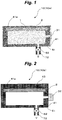
- an apparatus 10 (10a) for evaluating gas barrier properties is an apparatus for evaluating barrier properties against air that is installed in atmospheric air.
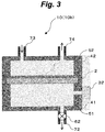
- a dense and smooth support 2 in the form of a flat sheet made of polycarbonate is fixed on an opening 41a side of a permeation-side chamber 41 using an adhesive.
- a permeation-side space 51 inside the permeation-side chamber 41 is decompressed to an industrial-level vacuum of, for example, 0.0 Pa through a valve 62 and a permeation-side gas outlet pipe 72 using a vacuum pump (not shown).
- Pressure inside the permeation-side chamber 41 is measured by a detection unit (pressure gauge) 31.
- Water vapor-transmission rate of the support 2 is 7.3 ⁇ 10 -11 mol/m 2 sPa, and air-transmission rate is 5 ⁇ 10 -13 mol/m 2 sPa.
- a sample 1 in the form of film is arranged in contact with the support 2, and the periphery of the sample 1 is sealed with a sealing material, for example, one made of beeswax. Then, if the valve 62 is closed, pressure in the permeation-side space 51 inside the permeation-side chamber 41 rises, due to air flowing through the sample 1 and the support 2 into the permeation-side space 51 inside the permeation-side chamber 41. Change thereof over time is examined.
- a sealing material for example, one made of beeswax
- the air-transmission rate of the sample 1 and support 2 combined calculated by formula (4) is 1.15 ⁇ 10 -13 mol/m 2 sPa.
- the air-transmission rate of the sample 1 and support 2 in combination calculated by formula (4) is 1.15 ⁇ 10 -14 mol/m 2 sPa.
- the air-transmission rate of the sample 1 calculated by formula (10) is 1.18 ⁇ 10 -14 mol/m 2 sPa. This value differs by only 2% from the air-transmission rate of the sample 1 and support 2 in combination. More specifically, with regard to a sample having low air-transmission rate, the air-transmission rate of the sample 1 and support 2 in combination is itself deemed in accordance with formula (11) to be the air-transmission rate of the sample 1.
- valve 62 is opened and the permeation-side space 51 inside the permeation-side chamber 41 is exhausted. With this state maintained as it is, the beeswax is melted by raising the temperature several tens of °C, whereafter the sample 1 can be demounted.
- gas (air)-transmission rate of the sample 1 can be evaluated with its shape maintained by the support 2.
- the support 2 is dense and smooth, so that the sample 1 sustains no deformation, resulting in no damage.
- the gas-transmission rate can be evaluated with high sensitivity by using an inexpensive pressure gauge without using a complicated and expensive analytical apparatus.
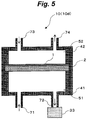
- an apparatus 10 (10b) for evaluating gas barrier properties is an apparatus for evaluating barrier properties against water vapor.
- the drawing shows a state before mounting a sample.
- a dense and smooth support 2 in the form of a flat sheet is fixed on an opening 41a side of a permeation-side chamber 41 using an adhesive.
- a cover 43 is placed on the support 2, and the periphery of the cover 43 is sealed with a sealing material, such as one made of beeswax.
- a permeation-side space 51 inside the permeation-side chamber 41 is decompressed to, for example, 1 ⁇ 10 -4 Pa, using a vacuum pump (not shown) through a valve 62 and a permeation-side gas outlet pipe 72. Water vapor partial pressure in the permeation-side space 51 inside the permeation-side chamber 41 is measured using a detection unit (mass spectrometer) 32.
- polyethylene terephthalate coated with silica is used for the support 2.
- Water vapor-transmission rate of this support is 1 ⁇ 10 -12 mol/m 2 sPa.
- a feed-side chamber 42 communicating with a feed-side gas inlet pipe 73 and a feed-side gas outlet pipe 74, is placed over the sample 1, and nitrogen of atmospheric pressure (standard atmospheric pressure 101.325 kPa), temperature of 40°C, and humidity of 90%RH is introduced into a feed-side space 52 inside the feed-side chamber 42 through the feed-side gas inlet pipe 73.
- temperature of 40°C temperature of 40°C
- humidity of 90%RH is introduced into a feed-side space 52 inside the feed-side chamber 42 through the feed-side gas inlet pipe 73.
- Water vapor pressure of this feed gas amounts to 6.6 kPa. Then, if the valve 62 is closed, water vapor partial pressure in the permeation-side space 51 inside the permeation-side chamber 41 rises, due to water vapor that flows into the permeation-side space 51 inside the permeation-side chamber 41 through the sample 1 and the support 2. Change thereof over time is examined.
- the water vapor-transmission rate of the sample 1 and support 2 combined calculated by formula (4) is 3.4 ⁇ 10 -15 mol/m 2 sPa.
- the water vapor-transmission rate of the support 2 is 1 ⁇ 10 -12 mol/m 2 sPa
- the water vapor-transmission rate of the sample 1 can be calculated by formula (10) to be 3.4 ⁇ 10 -15 mol/m 2 sPa.
- the rate expressed in terms of WVTR using formula (13) is 3.5 ⁇ 10 -5 g/m 2 day.
- gas (water vapor)-transmission rate of the sample 1 can be evaluated while maintaining the shape by the support 2.
- the support 2 is dense and smooth, so that the sample 1 is at not risk of damage owing to deformation.
- the permeation-side space 51 inside the permeation-side chamber 41 is not exposed to atmospheric air upon exchanging the samples 1, so that no water vapor in atmospheric air adheres to the inner wall of the permeation-side chamber 41.
- decompression of the permeation-side space 51 inside the permeation-side chamber 41 in evaluation causes only limited emission of water vapor from the inner wall, so that the baseline of the water vapor partial pressure can be held to a low level. Accordingly, small change in water vapor partial pressure can be measured.
- the water vapor barrier properties can be evaluated with high sensitivity.
- the time period required for the baseline of water vapor partial pressure to lower also becomes short, so that gas barrier properties can be evaluated in a short time period.
- This embodiment uses the support 2 having a water vapor-transmission rate of 1 ⁇ 10 -12 mol/m 2 sPa. If the operation from detaching the cover 43 to mounting the sample 1 is completed within one minute, pressure increase in the permeation-side space 51 inside the permeation-side chamber 41 due to permeation of water vapor from atmospheric air (assuming temperature of 25°C and humidity of 50%RH, which corresponds to a water vapor pressure of 1.6 kPa), calculated using formula (4), is 5 ⁇ 10 -5 Pa, which is sufficiently small. Even when the water vapor-transmission rate of the support 2 is 1 ⁇ 10 -10 mol/m 2 sPa, pressure increase in mounting the sample in one minute is 5 ⁇ 10 -3 Pa.
- a sample 1 can be mounted without stopping the mass spectrometer or performing a valve operation.
- acryl having a water vapor-transmission rate of 1.3 ⁇ 10 -9 mol/m 2 sPa is used for the support 2, pressure increase reaches 6 ⁇ 10 -2 Pa. Therefore, the apparatus must be stopped in the case of a mass spectrometer that does not operate at 10 -2 Pa or more.
- a detection unit 32 with high sensitivity can be safely used.
- the detection unit 32 with high sensitivity is designed so as to evaluate trace components, so that the unit 32 is at risk of being damaged if accidentally exposed to a normal pressure in the operation.
- the permeation-side space 51 inside the permeation-side chamber 41 is held at a low pressure at all times, including the time in sample exchange, as described above, and therefore the unit 32 is free from any worry about being damaged.
- the permeation-side space 51 inside the permeation-side chamber 41 is not directly exposed to atmospheric air upon exchanging samples, and the present invention therefore also has the advantage of experiencing no problem even when samples are exchanged in a place where no humidity control is conducted.
- the present invention also has the advantage of the differential-pressure method, in which carrier gas of high purity is unnecessary.
- nitrogen in addition to the water vapor, is also permeated therethrough in this evaluation, and the pressure in the permeation-side space 51 inside the permeation-side chamber 41 rises.
- an ordinary pressure gauge can be applied in place of the mass spectrometer.
- a nitrogen-transmission rate can also be evaluated by introducing dry nitrogen thereinto.
- the ordinary pressure gauge can be applied in place of the mass spectrometer.
- an apparatus 10 (10c) for evaluating gas barrier properties has a structure similar to that of the apparatus 10b for evaluating gas barrier properties shown in Fig. 3 , except that its support 2 has a shape for accommodating a sample 1 having a center projection.
- the present invention can be applied to samples having various shapes.
- an apparatus 10 (10d) for evaluating gas barrier properties has a structure similar to that of the apparatus 10b for evaluating gas barrier properties shown in Fig. 3 , except that a permeation-side gas inlet pipe 71 and a permeation-side gas outlet pipe 72 are connected with a permeation-side chamber 41, and that a mass spectrometer (atmospheric pressure ionization mass spectrometer) that can analyze a normal-pressure gas through the permeation-side gas outlet pipe 72 is provided as a detection unit 33.
- a mass spectrometer atmospheric pressure ionization mass spectrometer
- oxygen barrier properties When oxygen barrier properties are to be evaluated, dry nitrogen is introduced through the permeation-side gas inlet pipe 71 and dry oxygen is introduced into the feed-side gas inlet pipe 73. Oxygen on the feed side flows into the permeation-side space 51 through the sample 1 and the support 2, and oxygen partial pressure discharged from the permeation-side gas outlet pipe 72 therefore rises. The rise is analyzed with high sensitivity by the detection unit 33 formed of the atmospheric pressure ionization mass spectrometer, and change thereof is examined. Thus, permeability with respect to oxygen can be evaluated in a manner similar to the procedures in the second embodiment.
- the permeation-side space 51 inside the permeation-side chamber 41 is exposed to atmospheric air upon exchanging samples, and oxygen in atmospheric air is mixed thereinto. Therefore, it has been necessary to wait until the oxygen concentration becomes sufficiently low after samples are exchanged.
- the pressure on the feed side can be increased. Increasing the pressure on the feed side increases the driving force of oxygen permeation, so that a large amount of oxygen is permeated. As a result, a sample having low oxygen permeability can be readily evaluated.
- the gas permeability of the sample can be evaluated quickly, with high sensitivity, simply, and inexpensively, and high efficiency can therefore be achieved in the development of gas barrier films and the inspection of products prior to shipment.
- the thus developed and produced gas barrier film can be used for an organic electronics element, such as a solar cell or an organic light-emitting device, leading to an improvement in product life cycle.
- the gas barrier film can be used, in place of a bottle or a can, for food packaging that allows transparent packaging enabling long-period storage and visual recognition of contents.
Landscapes
- Chemical & Material Sciences (AREA)
- Physics & Mathematics (AREA)
- General Physics & Mathematics (AREA)
- Life Sciences & Earth Sciences (AREA)
- Pathology (AREA)
- Analytical Chemistry (AREA)
- Biochemistry (AREA)
- General Health & Medical Sciences (AREA)
- Health & Medical Sciences (AREA)
- Immunology (AREA)
- Dispersion Chemistry (AREA)
- Fluid Mechanics (AREA)
- Other Investigation Or Analysis Of Materials By Electrical Means (AREA)
- Chemical Kinetics & Catalysis (AREA)
- Electrochemistry (AREA)
- Sampling And Sample Adjustment (AREA)
- Examining Or Testing Airtightness (AREA)
Claims (7)
- Vorrichtung zur Beurteilung von Gasbarriereeigenschaften umfassend:einen Träger (2) zum Tragen einer Probe (1);eine Kammer (41) auf einer Gasdurchgangsseite; undeine Detektionseinheit (31, 32, 33), in welcher der Träger (2) mit einer Öffnung (41a) der Kammer (41) auf der Gasdurchgangsseite verbunden ist, um die Öffnung (41a) zu verschließen, undin welcher die Wasserdampfdurchlässigkeit des Trägers (2) 1×10⁻¹⁰ mol/m2sPa bis 1×10-14 mol/m2sPa beträgt,dadurch gekennzeichnet dass der Träger (2) und die Kammer (41) auf der Gasdurchgangsseite vereinigt sind auch wenn Proben (1) ausgetauscht werden.
- Vorrichtung zur Beurteilung von Gasbarriereeigenschaften nach Anspruch 1, wobei der Träger (2) ein Polymer ist.
- Vorrichtung zur Beurteilung von Gasbarriereeigenschaften nach Anspruch 1, wobei der Träger (2) ein organisches/anorganisches Verbundmaterial ist.
- Vorrichtung zur Beurteilung von Gasbarriereeigenschaften nach einem der Ansprüche 1 bis 3, wobei ein Druck innerhalb der Kammer (41) auf der Gasdurchgangsseite geringer ist als der Atmosphärendruck.
- Vorrichtung zur Beurteilung von Gasbarriereeigenschaften nach einem der Ansprüche 1 bis 4, wobei die Detektionseinheit (31, 32, 33) ein Druckmessgerät ist.
- Vorrichtung zur Beurteilung von Gasbarriereeigenschaften nach einem der Ansprüche 1 bis 4, wobei die Detektionseinheit (31, 32, 33) ein Massenspektrometer ist.
- Verfahren zur Beurteilung von Gasbarriereeigenschaften umfassend:Bereitstellung eines Trägers (2) zum Tragen einer Probe (1), einer Kammer (41) auf einer Gasdurchgangsseite, und einer Detektionseinheit (31, 32, 33),wobei der Träger (2) mit einer Öffnung (41a) der Kammer (41) auf der Gasdurchgangsseite verbunden ist, um die Öffnung (41a) zu verschließen, undwobei die Wasserdampfdurchlässigkeit des Trägers 1×10⁻¹⁰ mol/m2sPa bis 1×10-14 mol/m2sPa ist,dadurch gekennzeichnet dass der Träger (2) und die Kammer (41) auf der Gasdurchgangsseite vereinigt sind, auch wenn Proben (1) ausgetauscht werden,und dadurch, dass Proben (1) ausgetauscht werden während der Träger (2) mit der Kammer (41) auf der Gasdurchgangsseite verbunden ist.
Applications Claiming Priority (3)
| Application Number | Priority Date | Filing Date | Title |
|---|---|---|---|
| JP2013017821 | 2013-01-31 | ||
| JP2013270501A JP6304745B2 (ja) | 2013-01-31 | 2013-12-26 | ガスバリア性評価装置および評価方法 |
| PCT/JP2014/052165 WO2014119688A1 (ja) | 2013-01-31 | 2014-01-30 | ガスバリア性評価装置および評価方法 |
Publications (3)
| Publication Number | Publication Date |
|---|---|
| EP2952876A1 EP2952876A1 (de) | 2015-12-09 |
| EP2952876A4 EP2952876A4 (de) | 2016-10-05 |
| EP2952876B1 true EP2952876B1 (de) | 2017-11-08 |
Family
ID=51262393
Family Applications (1)
| Application Number | Title | Priority Date | Filing Date |
|---|---|---|---|
| EP14746091.9A Not-in-force EP2952876B1 (de) | 2013-01-31 | 2014-01-30 | Gasbarriereleistungbewertungsvorrichtung und bewertungsverfahren |
Country Status (6)
| Country | Link |
|---|---|
| US (1) | US9696251B2 (de) |
| EP (1) | EP2952876B1 (de) |
| JP (1) | JP6304745B2 (de) |
| KR (1) | KR102098430B1 (de) |
| CN (1) | CN104956204B (de) |
| WO (1) | WO2014119688A1 (de) |
Cited By (1)
| Publication number | Priority date | Publication date | Assignee | Title |
|---|---|---|---|---|
| WO2023095156A1 (en) | 2021-11-24 | 2023-06-01 | Chairman, Defence Research & Development Organisation (DRDO) | "apparatus and method for permeation testing of materials against chemicals" |
Families Citing this family (9)
| Publication number | Priority date | Publication date | Assignee | Title |
|---|---|---|---|---|
| FR2997763B1 (fr) * | 2012-11-06 | 2015-01-16 | Commissariat Energie Atomique | Dispositif et procede d'estimation d'un flux de gaz dans une enceinte maintenue en depression vis-a-vis du gaz |
| JP6345421B2 (ja) * | 2013-01-31 | 2018-06-20 | 国立研究開発法人産業技術総合研究所 | ガスバリア性評価装置および評価方法 |
| JP6865458B2 (ja) * | 2016-08-03 | 2021-04-28 | 株式会社日立ハイテクサイエンス | ガスバリア試験方法及び試験用治具 |
| KR102195770B1 (ko) | 2016-10-07 | 2020-12-28 | 가부시키가이샤 모레스코 | 접착제 조성물 및 이를 함유하는 접착제층, 지지 접합체 및 이 지지 접합체를 구비하는 가스 배리어성 평가 장치 |
| JP7041665B2 (ja) | 2017-02-27 | 2022-03-24 | 国立研究開発法人産業技術総合研究所 | ガスバリア性評価装置およびガスバリア性評価方法 |
| CR20170075A (es) * | 2017-03-01 | 2017-06-02 | Univ Costa Rica | Evaluador de microfiltración automático |
| CN107991219A (zh) * | 2017-12-29 | 2018-05-04 | 广州标际包装设备有限公司 | 一种水汽透过率测定仪 |
| KR102177152B1 (ko) * | 2020-07-30 | 2020-11-10 | 한국세라믹기술원 | 범용 건축자재 광촉매 성능평가 장치 |
| JP7663485B2 (ja) | 2021-12-17 | 2025-04-16 | 株式会社住化分析センター | チャンバー、ガス透過度測定装置、およびガス透過度測定方法。 |
Family Cites Families (20)
| Publication number | Priority date | Publication date | Assignee | Title |
|---|---|---|---|---|
| JPS59142438A (ja) * | 1983-02-04 | 1984-08-15 | Denshi Kagaku Kk | 透過膜支持容器の構造 |
| JP3474208B2 (ja) * | 1991-04-03 | 2003-12-08 | 株式会社日立製作所 | 気体試料又は液体試料中の少なくとも1種の揮発性成分を測定する装置及び測定法 |
| CN2148326Y (zh) * | 1993-02-03 | 1993-12-01 | 万昭志 | 新型气体透过率测定装置 |
| JP3264458B2 (ja) * | 1993-02-17 | 2002-03-11 | 三井化学株式会社 | フィルム用ガス透過率測定装置 |
| JP3453954B2 (ja) * | 1994-11-02 | 2003-10-06 | トヨタ自動車株式会社 | 一酸化炭素検出装置、有機化合物検出装置および低級アルコール検出装置 |
| JP2002357533A (ja) * | 2001-05-31 | 2002-12-13 | Sony Corp | 透過性評価方法及びその装置 |
| TW200422604A (en) * | 2002-12-25 | 2004-11-01 | Matsushita Electric Industrial Co Ltd | Gas permeability measurement method and gas permeability measurement device |
| JP3951972B2 (ja) | 2003-06-27 | 2007-08-01 | 凸版印刷株式会社 | フィルム状試料固定方法およびガスセル並びにガス透過度測定装置 |
| US6981403B2 (en) * | 2003-10-31 | 2006-01-03 | Mocon, Inc. | Method and apparatus for measuring gas transmission rates of deformable or brittle materials |
| JPWO2007036980A1 (ja) * | 2005-09-27 | 2009-04-02 | 凸版印刷株式会社 | ガスバリア性積層フィルム |
| FR2897434B1 (fr) * | 2006-02-15 | 2014-07-11 | Commissariat Energie Atomique | Procede et dispositif de mesure de permeation |
| KR20070050777A (ko) * | 2006-06-29 | 2007-05-16 | 주식회사 대우일렉트로닉스 | 투과량 측정 장치 |
| US7552620B2 (en) * | 2006-09-07 | 2009-06-30 | 3M Innovative Properties Company | Fluid permeation testing method employing mass spectrometry |
| ITPI20060108A1 (it) * | 2006-09-19 | 2008-03-20 | Extrasolution S R L | Metodo e dispositivo per misurare la permeabilita' di gas attraverso film sottile o pareti di contenitori |
| JP4855276B2 (ja) * | 2007-01-15 | 2012-01-18 | 株式会社アルバック | サンプル台、測定対象サンプル、透湿度測定装置 |
| CN101809427B (zh) * | 2007-09-28 | 2013-09-04 | 株式会社爱发科 | 测定水蒸气透过度的装置和方法 |
| JP2010190751A (ja) | 2009-02-18 | 2010-09-02 | Mitsubishi Chemicals Corp | フィルム材料のガス透過度測定装置及びガス透過度測定方法 |
| CN201867349U (zh) * | 2010-11-05 | 2011-06-15 | 济南兰光机电技术有限公司 | 等压法气体透过率测试系统 |
| CN202522503U (zh) * | 2012-03-27 | 2012-11-07 | 济南兰光机电技术有限公司 | 有机气体透过率测试装置 |
| JP6345421B2 (ja) * | 2013-01-31 | 2018-06-20 | 国立研究開発法人産業技術総合研究所 | ガスバリア性評価装置および評価方法 |
-
2013
- 2013-12-26 JP JP2013270501A patent/JP6304745B2/ja active Active
-
2014
- 2014-01-30 CN CN201480006892.4A patent/CN104956204B/zh not_active Expired - Fee Related
- 2014-01-30 EP EP14746091.9A patent/EP2952876B1/de not_active Not-in-force
- 2014-01-30 US US14/765,253 patent/US9696251B2/en not_active Expired - Fee Related
- 2014-01-30 KR KR1020157023237A patent/KR102098430B1/ko not_active Expired - Fee Related
- 2014-01-30 WO PCT/JP2014/052165 patent/WO2014119688A1/ja not_active Ceased
Non-Patent Citations (1)
| Title |
|---|
| None * |
Cited By (2)
| Publication number | Priority date | Publication date | Assignee | Title |
|---|---|---|---|---|
| WO2023095156A1 (en) | 2021-11-24 | 2023-06-01 | Chairman, Defence Research & Development Organisation (DRDO) | "apparatus and method for permeation testing of materials against chemicals" |
| EP4437322A4 (de) * | 2021-11-24 | 2025-08-20 | Chairman Defence Res And Development Organisation Drdo | Vorrichtung und verfahren zur permeationsprüfung von materialien gegen chemikalien |
Also Published As
| Publication number | Publication date |
|---|---|
| US9696251B2 (en) | 2017-07-04 |
| KR102098430B1 (ko) | 2020-04-07 |
| JP2014167465A (ja) | 2014-09-11 |
| KR20150110779A (ko) | 2015-10-02 |
| CN104956204A (zh) | 2015-09-30 |
| US20160003726A1 (en) | 2016-01-07 |
| JP6304745B2 (ja) | 2018-04-04 |
| EP2952876A4 (de) | 2016-10-05 |
| CN104956204B (zh) | 2018-04-24 |
| WO2014119688A1 (ja) | 2014-08-07 |
| EP2952876A1 (de) | 2015-12-09 |
Similar Documents
| Publication | Publication Date | Title |
|---|---|---|
| EP2952876B1 (de) | Gasbarriereleistungbewertungsvorrichtung und bewertungsverfahren | |
| EP2952877B1 (de) | Gasbarrierenleistungsbewertungsvorrichtung und bewertungsverfahren | |
| CN110140041B (zh) | 气体阻隔性评价装置及气体阻隔性评价方法 | |
| EP2113764B1 (de) | Feuchtigkeitskontrollsystem für die Sensorzelle eines Analytenpermeationstestgeräts | |
| CN101266234A (zh) | 多孔材料的快速完整性测试 | |
| GB2437136A (en) | Measuring rate of permeation | |
| CN107810398A (zh) | 测试容器的完整性测试方法和装置 | |
| CN112414920A (zh) | 无滤纸的压差法气体透过率测试系统 | |
| JP3930871B2 (ja) | 透湿度・気体透過度測定装置及び気体透過度測定方法 | |
| WO2017159481A1 (ja) | 被検査容器の漏洩検査方法、及び漏洩検査装置 | |
| KR20180069847A (ko) | 향상된 안정도의 필터 완전성 시험 | |
| CN103620364B (zh) | 用于检测柔性容器的方法和装置 | |
| WO2014012045A1 (en) | Method and apparatus for increasing the speed and/or resolution of gas permeation measurements | |
| JP5734109B2 (ja) | 測定装置および測定方法 | |
| CN214201096U (zh) | 无滤纸的压差法气体透过率测试系统 | |
| EP2969101B1 (de) | Vorrichtung und verfahren zur entgasung einer flüssigkeit auf einen kontrollierten pegel in einem verbundrohr | |
| JP6190485B2 (ja) | ガス透過度の測定方法および測定用キット | |
| JP2001021466A (ja) | 水素濃度検出装置 |
Legal Events
| Date | Code | Title | Description |
|---|---|---|---|
| PUAI | Public reference made under article 153(3) epc to a published international application that has entered the european phase |
Free format text: ORIGINAL CODE: 0009012 |
|
| 17P | Request for examination filed |
Effective date: 20150803 |
|
| AK | Designated contracting states |
Kind code of ref document: A1 Designated state(s): AL AT BE BG CH CY CZ DE DK EE ES FI FR GB GR HR HU IE IS IT LI LT LU LV MC MK MT NL NO PL PT RO RS SE SI SK SM TR |
|
| AX | Request for extension of the european patent |
Extension state: BA ME |
|
| DAX | Request for extension of the european patent (deleted) | ||
| A4 | Supplementary search report drawn up and despatched |
Effective date: 20160907 |
|
| RIC1 | Information provided on ipc code assigned before grant |
Ipc: G01N 15/08 20060101AFI20160901BHEP |
|
| GRAP | Despatch of communication of intention to grant a patent |
Free format text: ORIGINAL CODE: EPIDOSNIGR1 |
|
| STAA | Information on the status of an ep patent application or granted ep patent |
Free format text: STATUS: GRANT OF PATENT IS INTENDED |
|
| INTG | Intention to grant announced |
Effective date: 20170616 |
|
| GRAS | Grant fee paid |
Free format text: ORIGINAL CODE: EPIDOSNIGR3 |
|
| GRAA | (expected) grant |
Free format text: ORIGINAL CODE: 0009210 |
|
| STAA | Information on the status of an ep patent application or granted ep patent |
Free format text: STATUS: THE PATENT HAS BEEN GRANTED |
|
| AK | Designated contracting states |
Kind code of ref document: B1 Designated state(s): AL AT BE BG CH CY CZ DE DK EE ES FI FR GB GR HR HU IE IS IT LI LT LU LV MC MK MT NL NO PL PT RO RS SE SI SK SM TR |
|
| REG | Reference to a national code |
Ref country code: GB Ref legal event code: FG4D |
|
| REG | Reference to a national code |
Ref country code: CH Ref legal event code: EP Ref country code: AT Ref legal event code: REF Ref document number: 944594 Country of ref document: AT Kind code of ref document: T Effective date: 20171115 |
|
| REG | Reference to a national code |
Ref country code: IE Ref legal event code: FG4D |
|
| REG | Reference to a national code |
Ref country code: DE Ref legal event code: R096 Ref document number: 602014016910 Country of ref document: DE |
|
| REG | Reference to a national code |
Ref country code: NL Ref legal event code: MP Effective date: 20171108 |
|
| REG | Reference to a national code |
Ref country code: LT Ref legal event code: MG4D |
|
| REG | Reference to a national code |
Ref country code: AT Ref legal event code: MK05 Ref document number: 944594 Country of ref document: AT Kind code of ref document: T Effective date: 20171108 |
|
| PG25 | Lapsed in a contracting state [announced via postgrant information from national office to epo] |
Ref country code: FI Free format text: LAPSE BECAUSE OF FAILURE TO SUBMIT A TRANSLATION OF THE DESCRIPTION OR TO PAY THE FEE WITHIN THE PRESCRIBED TIME-LIMIT Effective date: 20171108 Ref country code: LT Free format text: LAPSE BECAUSE OF FAILURE TO SUBMIT A TRANSLATION OF THE DESCRIPTION OR TO PAY THE FEE WITHIN THE PRESCRIBED TIME-LIMIT Effective date: 20171108 Ref country code: SE Free format text: LAPSE BECAUSE OF FAILURE TO SUBMIT A TRANSLATION OF THE DESCRIPTION OR TO PAY THE FEE WITHIN THE PRESCRIBED TIME-LIMIT Effective date: 20171108 Ref country code: NL Free format text: LAPSE BECAUSE OF FAILURE TO SUBMIT A TRANSLATION OF THE DESCRIPTION OR TO PAY THE FEE WITHIN THE PRESCRIBED TIME-LIMIT Effective date: 20171108 Ref country code: NO Free format text: LAPSE BECAUSE OF FAILURE TO SUBMIT A TRANSLATION OF THE DESCRIPTION OR TO PAY THE FEE WITHIN THE PRESCRIBED TIME-LIMIT Effective date: 20180208 Ref country code: ES Free format text: LAPSE BECAUSE OF FAILURE TO SUBMIT A TRANSLATION OF THE DESCRIPTION OR TO PAY THE FEE WITHIN THE PRESCRIBED TIME-LIMIT Effective date: 20171108 |
|
| PG25 | Lapsed in a contracting state [announced via postgrant information from national office to epo] |
Ref country code: RS Free format text: LAPSE BECAUSE OF FAILURE TO SUBMIT A TRANSLATION OF THE DESCRIPTION OR TO PAY THE FEE WITHIN THE PRESCRIBED TIME-LIMIT Effective date: 20171108 Ref country code: HR Free format text: LAPSE BECAUSE OF FAILURE TO SUBMIT A TRANSLATION OF THE DESCRIPTION OR TO PAY THE FEE WITHIN THE PRESCRIBED TIME-LIMIT Effective date: 20171108 Ref country code: LV Free format text: LAPSE BECAUSE OF FAILURE TO SUBMIT A TRANSLATION OF THE DESCRIPTION OR TO PAY THE FEE WITHIN THE PRESCRIBED TIME-LIMIT Effective date: 20171108 Ref country code: AT Free format text: LAPSE BECAUSE OF FAILURE TO SUBMIT A TRANSLATION OF THE DESCRIPTION OR TO PAY THE FEE WITHIN THE PRESCRIBED TIME-LIMIT Effective date: 20171108 Ref country code: IS Free format text: LAPSE BECAUSE OF FAILURE TO SUBMIT A TRANSLATION OF THE DESCRIPTION OR TO PAY THE FEE WITHIN THE PRESCRIBED TIME-LIMIT Effective date: 20180308 Ref country code: GR Free format text: LAPSE BECAUSE OF FAILURE TO SUBMIT A TRANSLATION OF THE DESCRIPTION OR TO PAY THE FEE WITHIN THE PRESCRIBED TIME-LIMIT Effective date: 20180209 Ref country code: BG Free format text: LAPSE BECAUSE OF FAILURE TO SUBMIT A TRANSLATION OF THE DESCRIPTION OR TO PAY THE FEE WITHIN THE PRESCRIBED TIME-LIMIT Effective date: 20180208 |
|
| PG25 | Lapsed in a contracting state [announced via postgrant information from national office to epo] |
Ref country code: SK Free format text: LAPSE BECAUSE OF FAILURE TO SUBMIT A TRANSLATION OF THE DESCRIPTION OR TO PAY THE FEE WITHIN THE PRESCRIBED TIME-LIMIT Effective date: 20171108 Ref country code: CZ Free format text: LAPSE BECAUSE OF FAILURE TO SUBMIT A TRANSLATION OF THE DESCRIPTION OR TO PAY THE FEE WITHIN THE PRESCRIBED TIME-LIMIT Effective date: 20171108 Ref country code: DK Free format text: LAPSE BECAUSE OF FAILURE TO SUBMIT A TRANSLATION OF THE DESCRIPTION OR TO PAY THE FEE WITHIN THE PRESCRIBED TIME-LIMIT Effective date: 20171108 Ref country code: CY Free format text: LAPSE BECAUSE OF FAILURE TO SUBMIT A TRANSLATION OF THE DESCRIPTION OR TO PAY THE FEE WITHIN THE PRESCRIBED TIME-LIMIT Effective date: 20171108 Ref country code: EE Free format text: LAPSE BECAUSE OF FAILURE TO SUBMIT A TRANSLATION OF THE DESCRIPTION OR TO PAY THE FEE WITHIN THE PRESCRIBED TIME-LIMIT Effective date: 20171108 |
|
| REG | Reference to a national code |
Ref country code: DE Ref legal event code: R097 Ref document number: 602014016910 Country of ref document: DE |
|
| PG25 | Lapsed in a contracting state [announced via postgrant information from national office to epo] |
Ref country code: PL Free format text: LAPSE BECAUSE OF FAILURE TO SUBMIT A TRANSLATION OF THE DESCRIPTION OR TO PAY THE FEE WITHIN THE PRESCRIBED TIME-LIMIT Effective date: 20171108 Ref country code: IT Free format text: LAPSE BECAUSE OF FAILURE TO SUBMIT A TRANSLATION OF THE DESCRIPTION OR TO PAY THE FEE WITHIN THE PRESCRIBED TIME-LIMIT Effective date: 20171108 Ref country code: RO Free format text: LAPSE BECAUSE OF FAILURE TO SUBMIT A TRANSLATION OF THE DESCRIPTION OR TO PAY THE FEE WITHIN THE PRESCRIBED TIME-LIMIT Effective date: 20171108 Ref country code: SM Free format text: LAPSE BECAUSE OF FAILURE TO SUBMIT A TRANSLATION OF THE DESCRIPTION OR TO PAY THE FEE WITHIN THE PRESCRIBED TIME-LIMIT Effective date: 20171108 |
|
| REG | Reference to a national code |
Ref country code: CH Ref legal event code: PL |
|
| PLBE | No opposition filed within time limit |
Free format text: ORIGINAL CODE: 0009261 |
|
| STAA | Information on the status of an ep patent application or granted ep patent |
Free format text: STATUS: NO OPPOSITION FILED WITHIN TIME LIMIT |
|
| 26N | No opposition filed |
Effective date: 20180809 |
|
| PG25 | Lapsed in a contracting state [announced via postgrant information from national office to epo] |
Ref country code: LU Free format text: LAPSE BECAUSE OF NON-PAYMENT OF DUE FEES Effective date: 20180130 Ref country code: FR Free format text: LAPSE BECAUSE OF NON-PAYMENT OF DUE FEES Effective date: 20180131 |
|
| REG | Reference to a national code |
Ref country code: IE Ref legal event code: MM4A |
|
| REG | Reference to a national code |
Ref country code: FR Ref legal event code: ST Effective date: 20180928 |
|
| REG | Reference to a national code |
Ref country code: BE Ref legal event code: MM Effective date: 20180131 |
|
| PG25 | Lapsed in a contracting state [announced via postgrant information from national office to epo] |
Ref country code: SI Free format text: LAPSE BECAUSE OF FAILURE TO SUBMIT A TRANSLATION OF THE DESCRIPTION OR TO PAY THE FEE WITHIN THE PRESCRIBED TIME-LIMIT Effective date: 20171108 Ref country code: LI Free format text: LAPSE BECAUSE OF NON-PAYMENT OF DUE FEES Effective date: 20180131 Ref country code: CH Free format text: LAPSE BECAUSE OF NON-PAYMENT OF DUE FEES Effective date: 20180131 Ref country code: BE Free format text: LAPSE BECAUSE OF NON-PAYMENT OF DUE FEES Effective date: 20180131 |
|
| PG25 | Lapsed in a contracting state [announced via postgrant information from national office to epo] |
Ref country code: IE Free format text: LAPSE BECAUSE OF NON-PAYMENT OF DUE FEES Effective date: 20180130 |
|
| PG25 | Lapsed in a contracting state [announced via postgrant information from national office to epo] |
Ref country code: MC Free format text: LAPSE BECAUSE OF FAILURE TO SUBMIT A TRANSLATION OF THE DESCRIPTION OR TO PAY THE FEE WITHIN THE PRESCRIBED TIME-LIMIT Effective date: 20171108 |
|
| PG25 | Lapsed in a contracting state [announced via postgrant information from national office to epo] |
Ref country code: MT Free format text: LAPSE BECAUSE OF NON-PAYMENT OF DUE FEES Effective date: 20180130 |
|
| PG25 | Lapsed in a contracting state [announced via postgrant information from national office to epo] |
Ref country code: TR Free format text: LAPSE BECAUSE OF FAILURE TO SUBMIT A TRANSLATION OF THE DESCRIPTION OR TO PAY THE FEE WITHIN THE PRESCRIBED TIME-LIMIT Effective date: 20171108 |
|
| PG25 | Lapsed in a contracting state [announced via postgrant information from national office to epo] |
Ref country code: PT Free format text: LAPSE BECAUSE OF FAILURE TO SUBMIT A TRANSLATION OF THE DESCRIPTION OR TO PAY THE FEE WITHIN THE PRESCRIBED TIME-LIMIT Effective date: 20171108 |
|
| PG25 | Lapsed in a contracting state [announced via postgrant information from national office to epo] |
Ref country code: MK Free format text: LAPSE BECAUSE OF NON-PAYMENT OF DUE FEES Effective date: 20171108 Ref country code: HU Free format text: LAPSE BECAUSE OF FAILURE TO SUBMIT A TRANSLATION OF THE DESCRIPTION OR TO PAY THE FEE WITHIN THE PRESCRIBED TIME-LIMIT; INVALID AB INITIO Effective date: 20140130 |
|
| PG25 | Lapsed in a contracting state [announced via postgrant information from national office to epo] |
Ref country code: AL Free format text: LAPSE BECAUSE OF FAILURE TO SUBMIT A TRANSLATION OF THE DESCRIPTION OR TO PAY THE FEE WITHIN THE PRESCRIBED TIME-LIMIT Effective date: 20171108 |
|
| PGFP | Annual fee paid to national office [announced via postgrant information from national office to epo] |
Ref country code: GB Payment date: 20211122 Year of fee payment: 9 |
|
| PGFP | Annual fee paid to national office [announced via postgrant information from national office to epo] |
Ref country code: DE Payment date: 20211122 Year of fee payment: 9 |
|
| REG | Reference to a national code |
Ref country code: DE Ref legal event code: R119 Ref document number: 602014016910 Country of ref document: DE |
|
| GBPC | Gb: european patent ceased through non-payment of renewal fee |
Effective date: 20230130 |
|
| PG25 | Lapsed in a contracting state [announced via postgrant information from national office to epo] |
Ref country code: GB Free format text: LAPSE BECAUSE OF NON-PAYMENT OF DUE FEES Effective date: 20230130 Ref country code: DE Free format text: LAPSE BECAUSE OF NON-PAYMENT OF DUE FEES Effective date: 20230801 |