EP2952890B1 - Methode de balayage automatisé pour une inspection non destructrice de pièces de type cylindrique incurvées - Google Patents
Methode de balayage automatisé pour une inspection non destructrice de pièces de type cylindrique incurvées Download PDFInfo
- Publication number
- EP2952890B1 EP2952890B1 EP15165215.3A EP15165215A EP2952890B1 EP 2952890 B1 EP2952890 B1 EP 2952890B1 EP 15165215 A EP15165215 A EP 15165215A EP 2952890 B1 EP2952890 B1 EP 2952890B1
- Authority
- EP
- European Patent Office
- Prior art keywords
- sensor unit
- workpiece
- ndi sensor
- ndi
- curved
- Prior art date
- Legal status (The legal status is an assumption and is not a legal conclusion. Google has not performed a legal analysis and makes no representation as to the accuracy of the status listed.)
- Active
Links
Images


Classifications
-
- H—ELECTRICITY
- H04—ELECTRIC COMMUNICATION TECHNIQUE
- H04B—TRANSMISSION
- H04B7/00—Radio transmission systems, i.e. using radiation field
- H04B7/24—Radio transmission systems, i.e. using radiation field for communication between two or more posts
- H04B7/26—Radio transmission systems, i.e. using radiation field for communication between two or more posts at least one of which is mobile
- H04B7/2643—Radio transmission systems, i.e. using radiation field for communication between two or more posts at least one of which is mobile using time-division multiple access [TDMA]
- H04B7/2656—Radio transmission systems, i.e. using radiation field for communication between two or more posts at least one of which is mobile using time-division multiple access [TDMA] for structure of frame, burst
-
- B—PERFORMING OPERATIONS; TRANSPORTING
- B64—AIRCRAFT; AVIATION; COSMONAUTICS
- B64F—GROUND OR AIRCRAFT-CARRIER-DECK INSTALLATIONS SPECIALLY ADAPTED FOR USE IN CONNECTION WITH AIRCRAFT; DESIGNING, MANUFACTURING, ASSEMBLING, CLEANING, MAINTAINING OR REPAIRING AIRCRAFT, NOT OTHERWISE PROVIDED FOR; HANDLING, TRANSPORTING, TESTING OR INSPECTING AIRCRAFT COMPONENTS, NOT OTHERWISE PROVIDED FOR
- B64F5/00—Designing, manufacturing, assembling, cleaning, maintaining or repairing aircraft, not otherwise provided for; Handling, transporting, testing or inspecting aircraft components, not otherwise provided for
- B64F5/60—Testing or inspecting aircraft components or systems
-
- G—PHYSICS
- G01—MEASURING; TESTING
- G01N—INVESTIGATING OR ANALYSING MATERIALS BY DETERMINING THEIR CHEMICAL OR PHYSICAL PROPERTIES
- G01N29/00—Investigating or analysing materials by the use of ultrasonic, sonic or infrasonic waves; Visualisation of the interior of objects by transmitting ultrasonic or sonic waves through the object
- G01N29/04—Analysing solids
- G01N29/06—Visualisation of the interior, e.g. acoustic microscopy
- G01N29/0654—Imaging
-
- G—PHYSICS
- G01—MEASURING; TESTING
- G01N—INVESTIGATING OR ANALYSING MATERIALS BY DETERMINING THEIR CHEMICAL OR PHYSICAL PROPERTIES
- G01N29/00—Investigating or analysing materials by the use of ultrasonic, sonic or infrasonic waves; Visualisation of the interior of objects by transmitting ultrasonic or sonic waves through the object
- G01N29/22—Details, e.g. general constructional or apparatus details
- G01N29/26—Arrangements for orientation or scanning by relative movement of the head and the sensor
- G01N29/265—Arrangements for orientation or scanning by relative movement of the head and the sensor by moving the sensor relative to a stationary material
-
- G—PHYSICS
- G01—MEASURING; TESTING
- G01N—INVESTIGATING OR ANALYSING MATERIALS BY DETERMINING THEIR CHEMICAL OR PHYSICAL PROPERTIES
- G01N29/00—Investigating or analysing materials by the use of ultrasonic, sonic or infrasonic waves; Visualisation of the interior of objects by transmitting ultrasonic or sonic waves through the object
- G01N29/44—Processing the detected response signal, e.g. electronic circuits specially adapted therefor
-
- H—ELECTRICITY
- H04—ELECTRIC COMMUNICATION TECHNIQUE
- H04L—TRANSMISSION OF DIGITAL INFORMATION, e.g. TELEGRAPHIC COMMUNICATION
- H04L41/00—Arrangements for maintenance, administration or management of data switching networks, e.g. of packet switching networks
- H04L41/06—Management of faults, events, alarms or notifications
- H04L41/0695—Management of faults, events, alarms or notifications the faulty arrangement being the maintenance, administration or management system
-
- H—ELECTRICITY
- H04—ELECTRIC COMMUNICATION TECHNIQUE
- H04L—TRANSMISSION OF DIGITAL INFORMATION, e.g. TELEGRAPHIC COMMUNICATION
- H04L43/00—Arrangements for monitoring or testing data switching networks
- H04L43/16—Threshold monitoring
-
- H—ELECTRICITY
- H04—ELECTRIC COMMUNICATION TECHNIQUE
- H04W—WIRELESS COMMUNICATION NETWORKS
- H04W40/00—Communication routing or communication path finding
- H04W40/24—Connectivity information management, e.g. connectivity discovery or connectivity update
- H04W40/244—Connectivity information management, e.g. connectivity discovery or connectivity update using a network of reference devices, e.g. beaconing
-
- H—ELECTRICITY
- H04—ELECTRIC COMMUNICATION TECHNIQUE
- H04W—WIRELESS COMMUNICATION NETWORKS
- H04W72/00—Local resource management
- H04W72/04—Wireless resource allocation
- H04W72/044—Wireless resource allocation based on the type of the allocated resource
- H04W72/0446—Resources in time domain, e.g. slots or frames
-
- G—PHYSICS
- G01—MEASURING; TESTING
- G01N—INVESTIGATING OR ANALYSING MATERIALS BY DETERMINING THEIR CHEMICAL OR PHYSICAL PROPERTIES
- G01N2291/00—Indexing codes associated with group G01N29/00
- G01N2291/02—Indexing codes associated with the analysed material
- G01N2291/023—Solids
- G01N2291/0231—Composite or layered materials
-
- G—PHYSICS
- G01—MEASURING; TESTING
- G01N—INVESTIGATING OR ANALYSING MATERIALS BY DETERMINING THEIR CHEMICAL OR PHYSICAL PROPERTIES
- G01N2291/00—Indexing codes associated with group G01N29/00
- G01N2291/02—Indexing codes associated with the analysed material
- G01N2291/025—Change of phase or condition
- G01N2291/0258—Structural degradation, e.g. fatigue of composites, ageing of oils
-
- G—PHYSICS
- G01—MEASURING; TESTING
- G01N—INVESTIGATING OR ANALYSING MATERIALS BY DETERMINING THEIR CHEMICAL OR PHYSICAL PROPERTIES
- G01N2291/00—Indexing codes associated with group G01N29/00
- G01N2291/02—Indexing codes associated with the analysed material
- G01N2291/028—Material parameters
- G01N2291/0289—Internal structure, e.g. defects, grain size, texture
-
- G—PHYSICS
- G01—MEASURING; TESTING
- G01N—INVESTIGATING OR ANALYSING MATERIALS BY DETERMINING THEIR CHEMICAL OR PHYSICAL PROPERTIES
- G01N2291/00—Indexing codes associated with group G01N29/00
- G01N2291/26—Scanned objects
- G01N2291/263—Surfaces
- G01N2291/2634—Surfaces cylindrical from outside
-
- G—PHYSICS
- G01—MEASURING; TESTING
- G01N—INVESTIGATING OR ANALYSING MATERIALS BY DETERMINING THEIR CHEMICAL OR PHYSICAL PROPERTIES
- G01N2291/00—Indexing codes associated with group G01N29/00
- G01N2291/26—Scanned objects
- G01N2291/269—Various geometry objects
- G01N2291/2694—Wings or other aircraft parts
-
- H—ELECTRICITY
- H04—ELECTRIC COMMUNICATION TECHNIQUE
- H04W—WIRELESS COMMUNICATION NETWORKS
- H04W48/00—Access restriction; Network selection; Access point selection
- H04W48/16—Discovering, processing access restriction or access information
-
- H—ELECTRICITY
- H04—ELECTRIC COMMUNICATION TECHNIQUE
- H04W—WIRELESS COMMUNICATION NETWORKS
- H04W72/00—Local resource management
- H04W72/02—Selection of wireless resources by user or terminal
-
- H—ELECTRICITY
- H04—ELECTRIC COMMUNICATION TECHNIQUE
- H04W—WIRELESS COMMUNICATION NETWORKS
- H04W72/00—Local resource management
- H04W72/20—Control channels or signalling for resource management
- H04W72/23—Control channels or signalling for resource management in the downlink direction of a wireless link, i.e. towards a terminal
-
- Y—GENERAL TAGGING OF NEW TECHNOLOGICAL DEVELOPMENTS; GENERAL TAGGING OF CROSS-SECTIONAL TECHNOLOGIES SPANNING OVER SEVERAL SECTIONS OF THE IPC; TECHNICAL SUBJECTS COVERED BY FORMER USPC CROSS-REFERENCE ART COLLECTIONS [XRACs] AND DIGESTS
- Y02—TECHNOLOGIES OR APPLICATIONS FOR MITIGATION OR ADAPTATION AGAINST CLIMATE CHANGE
- Y02D—CLIMATE CHANGE MITIGATION TECHNOLOGIES IN INFORMATION AND COMMUNICATION TECHNOLOGIES [ICT], I.E. INFORMATION AND COMMUNICATION TECHNOLOGIES AIMING AT THE REDUCTION OF THEIR OWN ENERGY USE
- Y02D30/00—Reducing energy consumption in communication networks
- Y02D30/70—Reducing energy consumption in communication networks in wireless communication networks
Definitions
- This disclosure generally relates to non-destructive inspection equipment and methods, and relates more particularly to methods and apparatus for inspecting barrel-shaped structures made of composite material.
- Non-destructive inspection (NDI) of structures involves thoroughly examining a structure without harming the structure or requiring significant disassembly. Inspection may be performed during manufacturing of a structure and/or after a structure has been put in service to determine the condition, quality, or structural state of the structure.
- stiffeners stringers
- One existing solution involves rolling the barrel-shaped fuselage section in a rotating tool frame that allows each stiffener being inspected to be under a robotic crawler, so gravity is not an issue, and the stiffener crawlers holding multiple ultrasonic transducer (UT) arrays can crawl on a relatively horizontal surface.
- barrel-shaped workpieces such as fuselage sections that may include internal stiffening elements
- US3921440 (A ), in accordance with its abstract, states an ultrasonic inspection system for providing volumetric testing of circumferential welds in piping or other structural shapes of regular cross section.
- the inspection system permits inspection in longitudinal, circumferential shear, and axial shear modes and is characterized by having a carriage mountable on the pipe to be inspected with remote control of the position of the test head and remote gathering of data.
- an ultrasonic tester comprises an annular frame which is fitted over the pipe and which has a peripheral track for a carriage bearing an ultrasonic tester head which can be adjusted axially to different peripheral paths.
- the arcuate member is provided with means for rigid coupling to the remainder of the frame in its inwardly pivoted position.
- US2011178727 in accordance with its abstract, states an apparatus for non-destructive inspection of structural elements or workpieces, in particular those having an airfoil configuration, that moves a scanning sensor across the width (span) of a structural element or workpiece for the purpose of detecting structural damage.
- the apparatus simultaneously traverses the length (chord) of the structural element or workpiece.
- the apparatus includes a guide rail that encompasses the structural element or workpiece and the scanning sensor travels along the guide rail from a first location at an upper rear region, to the front, of the structural element or workpiece, and then around the leading edge toward the lower rear region.
- the apparatus includes a processor and a display device to display the processed, sensed, information
- US6137853 (A ), in accordance with its abstract, states a method and an apparatus for ultrasonically inspecting the welds which attach the differential pressure and liquid poison nozzles to the bottom head of the reactor pressure vessel in a boiling water reactor.
- the scanning apparatus is seated onthe upper taper of the nozzle outer tube and incorporates a stationary frame having a cutaway section which allows installation from the side.
- the apparatus has vertical and circumferential positioning mechanisms which are operated remotely to scan an ultrasonic transducer package over the circumferential welds and heat-affected zones thereof.
- the rotating frame has a transducer carriage mounted thereon which is vertically displaceable relative to the rotating frame.
- the vertical and angular motion motors can be controlled together to provide the desired path for the ultrasonic transducer around the stub tube.
- the tool also includes a vessel contour follower which follows the contour of the inclined surfaces of the reactor pressure vessel bottom head.
- the vessel contour follower is linked to the ultrasonic transducer to ensure that the transducer follows the contour of the weld, in position and angle.
- US2010275694 (A1) describes a pipe scanner for non-destructively scanning an extended length of the circumference of a pipe along an axial dimension.
- the pipe scanner includes a collar sized to fit around the outer circumference of the pipe and wheels supported on the collar ride on the surface of the pipe while maintaining a space between the inner surface of the collar and the outer surface of the pipe.
- a track extends circumferentially around the collar for guiding a circumferential drive unit that rides on the track and carries a non-destructive sensor for monitoring the surface of the pipe as the circumferential drive unit moves around the track.
- An axial drive unit is connected to the collar, having a plurality of circumferentially spaced drive wheels in contact with the pipe for moving the collar along the extended length.
- US2013145850 (A1 ), in accordance with its abstract, states a robotic inspection system that uses a pair of multi-axis robotic devices to perform an ultrasonic scan of a part.
- Each of the multi-axis robotic devices can comprise an end effector that can transmit and/or receive an ultrasonic signal to perform the ultrasonic scan.
- the robotic inspection system includes a linear slide assembly that can translate the multi-axis robotic devices independently from one another on either side of the part.
- a phased array ultrasonic probe may be mounted to a component to be inspected for wall thickness on an apparatus that includes a split ring adapted to be magnetically held in place on the component.
- the probe may be mounted to a carriage connected to the split ring in a manner that allows the carriage to rotate around the split ring while the probe is in operation.
- a transducer shoe Between the probe and the component, a transducer shoe defining, by a flexible membrane, a cavity and an aperture.
- the construction of the flexible membrane allows wall thickness measurements to be acquired in portions of the component that have complex topography, such as welds.
- the apparatus is installed on an adaptor assembly for inspection of straight section of pipes. This adaptor assembly is not used in absence of straight section.
- US4375165 (A ), in accordance with its abstract, states an ultrasonic flaw detection system is used for inspecting circumferentially welded joints in a pipeline.
- the ultrasonic probes include crystals for directing and receiving longitudinal waves reflected from the pipe interior surface in order to measure the pipe thickness.
- a gating device is timed on the basis of the measured pipe thickness and enables the angled crystals to receive transverse ultrasonic waves from weld defects and avoids recording reflections due to weld geometry.
- a manipulation device having a guide band positioned around the pipe and an eccentric movable toward and away from the band may be used for clamping the carriage to the band.
- US4672852 in accordance with its abstract, states a test manipulator externally applicable to a pipe, preferably for ultrasonically testing welded seams, the manipulator having a divided race for surrounding a pipe which is to be tested, a guide segment guiding the race at the periphery thereof, a test system carrier drivable in peripheral direction around the pipe, a driving and positioning device for the test system carrier and at least one test head holder fastenable to the test system carrier includes clamping means for fastening the race directly to the pipe in centered relationship to an adjustment mark located on the pipe; a guide segment mounted so as to be movable along the periphery of the race; an outrigger unit flangeable, together with the test system carrier and the test head holder, to the guide segment; and a saddle fastenable to the pipe in centered relationship to the adjustment mark; alternatively, during testing of a so-called pipe connection seam, the guide segment being movable on the saddle in axial direction of the pipe, and the race, together with
- the subject matter disclosed herein is directed to systems and methods for high-speed non-destructive inspection of a curved cylinder-like workpiece (e.g., in the shape of a half or full barrel).
- the curved cylinder-like workpiece may be a large-scale part, thereby taking advantage of automation provided by embodiments disclosed herein.
- the curved cylinder-like workpiece is an aircraft part, and in particular a barrel-shaped section of an aircraft fuselage.
- the curved cylinder-like workpiece may be made of any material as desired for a particular application. It will be appreciated that the type of material used for the curved cylinder-like workpiece may, in part, determine which type of non-destructive inspection technique is used to inspect the curved cylinder-like workpiece.
- the curved cylinder-like workpiece may be made of composite material, such as a composite laminate made of fiber-reinforced plastic, or a metal, such as aluminum or titanium. It will be understood that it is not intended to limit in any manner whatsoever the materials from which the curved cylinder-like workpiece may be made.
- any one of a multiplicity of types of NDI sensors can be utilized.
- a variety of types of NDI sensors suitable for use with the scanning apparatus disclosed herein are listed and described in U.S. Patent No. 7,743,660 entitled “System and Method for Automated Inspection of Large-Scale Part".
- the NDI sensor units are supported by apparatus that travels along tracks.
- tracks encompasses rails, grooves, guide surfaces, and equivalents thereof.
- a track may be straight (i.e., linear) or curved.
- an NDI sensor unit is mounted to a carriage that travels circumferentially along a curved track formed by guide surfaces, which curved track in turn is mounted to an arch frame that travels longitudinally along linear tracks in the form of rails.
- the scanning system may comprise means for scanning the skin of the fuselage section from a vantage point external to the fuselage section and means for scanning substructure, such as stringers attached to the inside of a stiffened fuselage section.
- the means for scanning the stiffeners on the inside of a fuselage section can work in concert and concurrently with the means that scan the fuselage section externally.
- the fuselage sections can be scanned externally before or after the stiffeners have been attached.
- the scanning means comprise multiple linear UT arrays that collect wide swaths of ultrasonic data. In one configuration, some UT arrays sweep the outer mold line of the fuselage section circumferentially, while other UT arrays travel longitudinally along the length of the stiffeners attached to the inside of the fuselage section.
- the fuselage sections are scanned externally using a mobile (e.g., translating) arch gantry system comprising a translatable arch frame disposed outside the fuselage section, a carriage that can travel along a curved track carried by the arch frame, a radially extending telescopic arm having a proximal end fixedly coupled to the carriage, and an NDI sensor unit coupled to a distal end of the telescoping arm.
- a mobile (e.g., translating) arch gantry system comprising a translatable arch frame disposed outside the fuselage section, a carriage that can travel along a curved track carried by the arch frame, a radially extending telescopic arm having a proximal end fixedly coupled to the carriage, and an NDI sensor unit coupled to a distal end of the telescoping arm.
- the stiffeners of the fuselage sections can be scanned using a mobile scanner platform disposed inside the fuselage section, which platform comprises a radially extending telescopic arm rotatably coupled to a mobile (e.g., holonomic or linear motion) platform and an NDI sensor unit coupled to a distal end of the telescoping arm.
- the scan data is matched with position data acquired using any one of a plurality of tracking systems to enable the display of NDI features/flaws on a three-dimensional representation of the workpiece.
- the entire OML of the half-barrel fuselage section can be scanned externally using an arch gantry system by moving the latter in increments from one end of the fuselage section to the other end, stopping after each incremental advance to perform a circumferential scan of a respective swath of the fuselage section.
- one half of the full-barrel fuselage section can be scanned externally from one end to the other; then the fuselage section is rotated 180 degrees about its longitudinal axis in the arch gantry system and then the other half of the fuselage section can be scanned externally from one end to the other.
- One aspect of the subject matter disclosed in detail below is a method for scanning a workpiece having a curved section that extends longitudinally and circumferentially, the method comprising: (a) moving a curved track to a first longitudinal position relative to the workpiece, the curved track being disposed radially outward from the curved section of the workpiece; (b) moving an NDI sensor unit along the curved track while the curved track is stationary at the first longitudinal position; (c) during step (b), activating the NDI sensor unit to inspect a first strip-shaped area of the curved section of the workpiece; (d) processing signals output from the NDI sensor unit to derive a first strip of scan data characterizing a structural state of the first strip-shaped area of the curved section of the workpiece; (e) during step (b), acquiring location data representing locations of the NDI sensor unit relative to the workpiece; and (f) mapping the first strip of scan data to a three-dimensional model of the workpiece based on the location data acquired in step (e
- the workpiece may be a fuselage section made of composite material.
- the method may further comprise displaying features overlaid on a representation of a portion of the three-dimensional model of the workpiece based on the results of steps (d) and (f).
- the method further comprises the following steps: (g) subsequent to step (b), moving the curved track from the first longitudinal position to a second longitudinal position relative to the workpiece; (h) moving the NDI sensor unit along the curved track while the curved track is stationary at the second longitudinal position; (i) during step (h), activating the NDI sensor unit to inspect a second strip-shaped area of the curved section of the workpiece; (j) processing signals output from the NDI sensor unit to derive a second strip of scan data characterizing a structural state of the second strip-shaped area of the curved section of the workpiece; (k) during step (h), acquiring location data representing locations of the NDI sensor unit relative to the workpiece; and (l) mapping the second strip of scan data to the three-dimensional model
- Another example related to the invention is a system for external scanning of a workpiece having a curved outer mold line, the system comprising: first and second linear tracks which are mutually parallel; a curved track disposed in a plane generally transverse to the first and second linear tracks, the curved track being coupled to and translatable along the first and second linear tracks; a carriage coupled to and movable along the curved track; an extendible arm having a proximal end coupled to the carriage; an NDI sensor unit coupled to a distal end of the extendible arm; a location tracking system capable of tracking the location of the NDI sensor unit relative to the workpiece; a data processing system capable of receiving scan data from the NDI sensor unit and location tracking data from the location tracking system and then correlating the scan data with the location tracking data; and a display system capable of displaying the scan data on a three-dimensional representation of the workpiece (such as with three-dimensional representation of the workpiece (such as with texture maps) based on results of the correlating process performed by the data processing system
- a further non-claimed example of the disclosed subject matter is a system for scanning a workpiece having a curved section that extends longitudinally and circumferentially, the system comprising: a pair of linear tracks parallel to a longitudinal direction; an arch frame that extends circumferentially and is arranged to travel along the linear tracks; a first actuator which, when activated, causes the arch frame to travel along the linear tracks; a curved track supported by the arch frame; a carriage arranged to travel along the curved track; a second actuator which, when activated, causes the carriage to travel along the curved track; an extendible arm comprising a first member mounted to the carriage and a second member which is arranged to translate relative to the first member; a third actuator which, when activated, causes the second member to translate relative to the first member; and an NDI sensor unit mounted to the second member and operable to acquire scan data during its motion.
- a non-claimed example of the disclosed subject matter is a system for scanning a substructure of a curved cylinder-like workpiece, which substructure extends along an inner surface of the workpiece.
- the system comprises: a mobile platform comprising a frame; a first actuator which, when activated, exerts a force urging the mobile platform to move; an extendible arm comprising a first member pivotably mounted to the frame of the mobile platform and a second member which is translatable relative to the first member; a second actuator which, when activated, exerts a force urging the second member to translate relative to the first member; and a first NDI sensor unit coupled to a distal end of the extendible arm; an encoder device capable of outputting signals representing incremental movements of the first NDI sensor unit along a substructure; and a computer system programmed to perform the following operations: controlling the first and second actuators and the first NDI sensor unit; receiving signals from the encoder device; converting signals from the encoder device into position data representing a position of the first ND
- a further non-claimed example of the disclosed subject matter is a system for scanning a stiffened curved cylinder-like workpiece, the system comprising: first means for circumferentially scanning an outer mold line of the workpiece; and second means for scanning a longitudinal stiffener attached to an inner mold line of the workpiece, wherein the first and second means work in concert and concurrently.
- the system may further comprise an arch frame disposed outside the workpiece and comprising a curved track, the arch frame being translatable along a longitudinal axis of the workpiece, wherein the first means comprise: a carriage that can travel along the curved track; a radially extending telescopic arm having a proximal end fixedly coupled to the carriage; and an NDI sensor unit coupled to a distal end of the telescoping arm.
- the system may further comprise a mobile scanner platform disposed inside the workpiece, wherein the second means comprise: a radially extending telescopic arm rotatably coupled to the mobile scanner platform; and an NDI sensor unit coupled to a distal end of the telescoping arm.
- a system for scanning a workpiece having a curved section that extends longitudinally and circumferentially comprising: a pair of linear tracks parallel to a longitudinal direction; an arch frame that extends circumferentially and is arranged to travel along said linear tracks; a first actuator which, when activated, causes said arch frame to travel along said linear tracks; a curved track supported by said arch frame; a carriage arranged to travel along said curved track; a second actuator which, when activated, causes said carriage to travel along said curved track; an extendible arm comprising a first member mounted to said carriage and a second member which is arranged to translate relative to said first member; a third actuator which, when activated, causes said second member to translate relative to said first member; and an NDI sensor unit mounted to said second member and operable to acquire scan data during its motion.
- the system further comprises: a first encoder device that outputs signals representing incremental movements of said arch frame along said linear tracks; a second encoder device that outputs signals representing incremental movements of said carriage along said curved track; a third encoder device that outputs signals representing a distance that said second member of said extendible arm has traveled relative to said first member; and a computer system programmed to be capable of performing the following operations: (a) tracking the location of said NDI sensor unit to acquire location data representing locations of said NDI sensor unit based on signals outputted by said first, second and third encoder devices; (b) controlling said first, second and third actuators to cause said NDI sensor unit to travel along said curved track from a first circumferential position to a second circumferential position while said NDI sensor unit is adjacent to an outer mold line of the workpiece and said curved track is stationary; (c) while said NDI sensor unit is traveling along said curved track from the first circumferential position to the second circumferential position and said curved track is stationary, controlling said NDI
- the system further comprises a display monitor, wherein said computer system is further programmed to control said display monitor to display the strip of scan data overlaid on an image of a three-dimensional representation of the workpiece.
- said computer system comprises: a data acquisition device connected to receive signals outputted by said second and third encoder devices and programmed to convert those signals into simulated encoder pulses; and an inspection scanning subsystem connected to receive simulated encoder pulses from said data acquisition device and scan data from said NDI sensor unit, and programmed to decode received simulated encoder pulses into position data and then associate that position data with the scan data for display, wherein the position data represents coordinates of said NDI sensor unit with respect to the coordinate system of the workpiece.
- the system further comprises a first plurality of retro-reflective markers attached to the workpiece; a second plurality of retro-reflective markers attached to said arch frame; a third plurality of retro-reflective markers attached to said extendible arm; a plurality of cameras having said retro-reflective markers within respective fields of view; a motion capture subsystem programmed to convert images from said cameras into calibration data representing a position and an orientation of the workpiece with respect to a motion capture coordinate system and first location data representing positions and orientations of said NDI sensor unit with respect to the motion capture coordinate system during movement of said NDI sensor unit; and a motion tracking subsystem connected to receive said first location data from said motion capture subsystem and programmed to output second location data which is a function of the first location data received from said motion capture subsystem, said second location data representing positions and orientations of said NDI sensor unit with respect to a coordinate system of the workpiece.
- a system for scanning a stiffened curved cylinder-like workpiece comprising: first means for circumferentially scanning an outer mold line of the workpiece; and second means for scanning a longitudinal stiffener attached to an inner mold line of the workpiece, wherein said first and second means work in concert and concurrently.
- the system further comprises an arch frame disposed outside the workpiece and comprising a curved track, said arch frame being translatable along a longitudinal axis of the workpiece, wherein said first means comprise: a carriage that can travel along said curved track; a radially extending telescopic arm having a proximal end fixedly coupled to said carriage; and an NDI sensor unit coupled to a distal end of the telescoping arm.
- said first means comprise: a carriage that can travel along said curved track; a radially extending telescopic arm having a proximal end fixedly coupled to said carriage; and an NDI sensor unit coupled to a distal end of the telescoping arm.
- the system further comprises a mobile scanner platform disposed inside the workpiece, wherein said second means comprise: a radially extending telescopic arm rotatably coupled to said mobile scanner platform; and an NDI sensor unit coupled to a distal end of said telescoping arm.
- drawings representing views of physical structures are not drawn to scale. Also, it should be noted that the drawings representing physical structures do not show the flexible cables which electrically connect the hardware to a computer system (not shown) and, in the case of ultrasonic inspection, which connect an ultrasonic transducer inspection unit to a source of acoustic couplant (e.g., water).
- acoustic couplant e.g., water
- curved cylinder-like workpieces in the form of half- or full-barrel-shaped sections of an aircraft fuselage
- the apparatus and methods disclosed herein may also be used for similar applications which require non-destructive inspection, including other curved cylinder-like workpieces.
- workpieces may comprise shells or half-shells having a curved cross-sectional profile (e.g., an oval, ellipse, or circle, or any section thereof) that is constant or varies smoothly in a longitudinal direction.
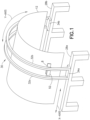
- FIG. 1 represents an isometric view of portions of an external scanning system for ultrasonic inspection of the OML of a half-barrel fuselage section 12 in accordance with one embodiment. (The same external scanning system can be adapted to inspect respective halves of the OML of a full-barrel fuselage section.) Means for supporting the half-barrel fuselage section 12 are not shown in FIG. 1 .
- an NDI sensor unit 8 is scanned circumferentially (i.e., along a Y-axis) across the OML of the half-barrel fuselage section 12 at successive longitudinal positions (i.e., spaced along an X-axis).
- the NDI sensor unit 8 takes the form of multiple ultrasonic transducer (UT) elements lined up in an array and contained in a structure called a shoe, mounted to an end effector (not shown), to provide for a wide scan.
- the NDI sensor unit 8 acquires a respective swath of ultrasound scan data. Successive swaths of ultrasound scan data may be acquired from successive contiguous segments of the half-barrel fuselage section 12 to provide full scan coverage from one end of the half-barrel fuselage section 12 to the other end.
- the NDI sensor unit 8 is supported by a translatable arch gantry system 30 comprising a pair of arch frame members 32a, 32b connected at their opposing ends to gantry trolleys 34a and 34b.
- the gantry trolleys 34a and 34b ride on linear rails (not shown in the drawings) of respective rail assemblies 28a and 28b.
- the gantry trolleys 34a and 34b may comprise rollers that roll along the linear rails.
- other systems for guiding linear motion could be employed.
- the gantry trolleys 34a and 34b may be equipped with sliders comprising respective pairs of recirculating ball bearings that roll along a pair of linear guide tracks.
- each gantry trolley 34a, 34b can be measured by a respective position sensor (e.g., an encoder) to provide feedback to a trolley motion control subsystem (not shown in FIG. 1 ) which controls the X-direction motion of the arch gantry system 30.
- a respective position sensor e.g., an encoder
- the half-barrel fuselage section 12 is positioned so that its longitudinal axis (not shown in the drawings) will be parallel to the X axis.
- the arch frame members 32a and 32b are provided with mutually parallel curved tracks (not visible in FIG. 1 ) preferably disposed in planes transverse to the linear rails of rail assemblies 28a and 28b.
- the NDI sensor unit 8 is coupled to a carriage 52 which is designed to travel along the curved tracks. As the carriage 52 travels along the curved tracks (while the arched gantry system 30 is stationary), the NDI sensor unit 8 can be activated to scan a circumferential portion of the OML of the half-barrel fuselage section 12 from one side edge to the other side edge.
- the curved tracks may be constructed so that their curvatures approximate the curvature of the workpiece, with a compliant end effector compensating for slight to moderate curvature mismatch.
- the curvature of the half-barrel fuselage section 12 may be circular, elliptical, oval, or some other shape.
- the carriage 52 may comprise respective motorized trolleys which travel along the curved tracks of the arch frame members 32a and 32b, thereby scanning the NDI sensor unit 8 circumferentially across the OML of the half-barrel fuselage section 12.
- the extendible arm 62 is retracted to lift the NDI sensor unit 8 from the surface and returned to its starting position along the arch frame members 32a and 32b.
- the extendable arm 62 is shifted over to the location of the next strip without retracting and returning to its starting position.
- the arch gantry system 30 is automatically moved along the X-axis by a distance equal to the width of the swath of scan data acquired. This process is repeated until the entire OML of the half-barrel fuselage section 12 has been scanned. Then the half-barrel fuselage section 12 is removed and the next half-barrel fuselage section is placed in position for external scanning (or in some embodiments, the interior is scanned by another system before the barrel is moved out). In the case of external scanning of a full-barrel fuselage section, first one half of the full barrel is scanned; then the full barrel is rotated 180 degrees and the other half is scanned. Then the full barrel is removed and a next full-barrel fuselage section is placed in position for external scanning.
- two or more arch gantry systems of the type shown in FIG. 1 can be mounted to the rail assemblies 28a and 28b for scanning respective portions of the half-barrel fuselage section 12 concurrently.
- the rate of inspection can be increased.
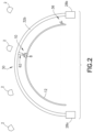
- FIG. 2 is an end view of portions of an external scanning system of the type shown in FIG. 1 wherein the location of the NDI sensor unit 8 is tracked using a motion capture system.
- the NDI sensor unit 8 is coupled to the carriage (not visible in FIG. 2 ) by means of an extendible arm 62.
- the extendible arm 62 is in a retracted position during longitudinal movement of the arch gantry system 30. Prior to initiation of a circumferential scanning operation, the extendible arm 62 is actuated to extend, bringing the shoe of the NDI sensor unit 8 into contact with the OML of the fuselage section 12.
- the extendible arm may be extended to bring the NDI sensor unit into proximity without contacting the OML of the workpiece.
- the NDI scanning assembly further comprises an extendible arm 62 in the form of a telescoping arm comprising an outer sleeve 64 attached to the carriage 52 and an inner sleeve 66 which is axially translatable inside the outer sleeve 64.
- Linear motion of the inner sleeve 66 can be actuated via hydraulics, pneumatics, or a motor turning a threaded screw.
- the linear motion actuator comprises a lead screw (not shown) coupled to the output shaft of a motor 68 (for example, a stepper motor) and threadably coupled to a nut (not shown) attached to the inner sleeve 66.
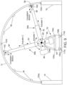
- the positions of all of the retro-reflective markers 10 in the capture volume V can be captured by each camera 2 and converted by the motion capture processor 14 into three-dimensional coordinates, which are then associated with the known marker pattern attached to the NDI sensor unit 8, resulting in full 6-DOF position and orientation representations for the NDI sensor unit 8.
- a separate data conversion application running on motion tracking and applications computer 16 accesses this object position/orientation data (also referred to herein as "location data”) through a network socket connection to the motion capture processor 16.
- the NDI scanner hardware 22 is an integrated unit comprising a pulser, a receiver and an electronics box.
- the NDI sensor unit 8 is capturing inspection data (e.g., scan imaging data).
- inspection data e.g., scan imaging data
- data from each element of a linear array of ultrasonic elements can be acquired. These elements make up an array that is analogous to a row of pixels on a computer monitor (where each row is offset from the next by defining the starting X,Y position of the first pixel and when all the rows are displayed in proper order, a full image can be displayed).
- the NDI scanner hardware 22 receives a new strip of scan data from the NDI sensor unit 8 (representing a "row" of pixel data) via cable 11. Each strip of scan data is saved to memory.
- the NDI software uses the current X_pos and Y_pos data derived from the received pulse data to locate the starting point in the image where to place the row of pixels.
- the NDI scanner hardware 22 associates the position data and the scan imaging data.
- the associated data is then sent to an NDI analysis and display computer 24, which uses the position data and scan imaging data to assemble a two-dimensional image of the object being scanned for display on display monitor 26.
- the NDI scanner hardware 22 and the NDI analysis and display computer 24 may be connected components of a phased array acquisition instrument such as the TomoScan FOCUS LT, which is commercially available from Olympus Corporation.
- the position data derived from the simulated encoder pulses enables the NDI analysis and display computer 24 to compute and display a final C-scan image.
- the C-scan presentation provides a plan-type view of the location and size of part features. In the case of ultrasound imaging, the plane of the image is parallel to the scan pattern of the ultrasonic transducer array of the NDI sensor unit. In a C-scan, there is location information shown in the display. The location is found along the horizontal and vertical axes (or rulers) of the NDI data display. Individual pixels make up the C-scan.
- each pixel directly corresponds to a specific number of pulses, which is defined by the resolution of a simulated dimensional encoder associated with a first axis of the part, while the height of each pixel directly corresponds to a specific number of pulses, which is defined by the resolution of a simulated dimensional encoder associated with a second axis of the part which is perpendicular to the first axis.
- Operators are able to make area measurements of flaws that might show up in the C-scan.
- the 3-D model of the fuselage section, the NDI sensor unit location data, and the scan data can be used to generate the three-dimensional image graphically represented in FIG. 3 .
- FIG. 5 shows one possible configuration for a system of a non-claimed example, but other configurations are also possible, such as having the motion capture and application software running on a single computer, or combining the NDI scanning system components into a single device. More details concerning the motion capture process can be found in U.S. Patent Application No. 13/744,730 .
- the location of the NDI sensor unit 8 can be tracked using positional encoders only that measure incremental movements of: (1) the arch frame 50 along the linear rails; (2) the carriage 52 along the curved tracks of the arch frame 50; and (3) the inner sleeve 66 of the extendible arm 62 relative to the outer sleeve 64.
- the encoder-based solution uses three separate linear encoders.
- FIG. 6 is a block diagram showing components of a control system that uses rotational or linear encoders to track the relative location (e.g., relative to an initial location acquired using a local positioning system) of an NDI sensor unit mounted to an external scanning system of the type partly depicted in FIG. 1 .
- the control system comprises a ground-based computer 150 programmed with motion control application software 152 and NDI scan application software 154.
- the control computer 150 is connected to an X-axis motion motor 160 (which drives translation of the arch gantry system 30 along the linear rails), a radial sweep (i.e., Y-axis motion) motor 164 (which drives circumferential movement of carriage 52 along the curved tracks of the arch gantry system 30), and an extension (i.e., Z-axis motion) motor 168 (which drives extension/retraction of the extendible arm 62).
- the control computer 150 may comprise a general-purpose computer programmed with motion control application software 152 comprising respective software modules for controlling the motors.
- the motion control application 152 controls the operation of the motors based on position feedback from respective encoders, namely, X-axis encoder 162, Y-axis encoder 166, and Z-axis encoder 170.
- Motion control application software 152 controls the extension motor 168 to produce specified radial motion of the UT arrays 73.
- the range of radial motion of the UT arrays 73 in both directions may be limited by limit switches (not shown).
- the Z-axis encoder 170 measures the angular position of the output shaft of an extension motor 168 that drives rotation of a lead screw, which angular position in turn determines the radial displacement of the ultrasonic transducer arrays 73 effectuated by the extendible arm 62.
- the motion control application software 152 is thus capable of moving the UT array 73 circumferentially along the OML of the fuselage section being inspected.
- the encoded data from linear encoders 162, 166 and 170 is received by a data acquisition device 20.
- the data acquisition device 20 also has digital input and output connections that are used for multiple functions within the system.
- the fuselage section 12 is moved into position under the arch gantry system 30.
- the arch gantry system 30, carriage 52 and extendible arm 62 should be in their respective starting positions.
- the motion capture system is turned on and correlated to the retro-reflective markers 10 attached to the scan shoe of the NDI sensor unit 8 and to the retro-reflective targets 36 which are temporarily attached to the fuselage section 12.
- the radial motion actuator is activated so that the NDI sensor unit 8 is moved circumferentially from one side edge of a half-barrel fuselage section 12 to the other side edge.
- the arch gantry system 30 is moved axially along the linear rails to an adjacent location (displaced by the width of the circumferentially scanned area from the previous location).
- the radial motion actuator is reactivated to collect the adjacent swath of scan data, and this is repeated down the length of the half-barrel fuselage section 12 until the scan is completed. If a full-barrel fuselage section is being scanned, the fuselage section is rotated 180 degrees about the longitudinal (roll) axis and the process is repeated.
- each hat stringer is a trapezoidal structure comprising angled sides which connect to a cap at respective cap corners.
- Each hat stringer is affixed to the skin of the fuselage section by respective flanges which connect to the angled sides of the hat stringer at respective flange corners.
- one approach is known using a suite of seven transducer arrays: one to inspect a central cap portion; two to inspect angled sides; two to inspect cap corners; and two to inspect flange corners.
- corner refers to a radiused (i.e., filleted) intersection of surfaces.
- the central cap portion may be a planar surface connecting the cap corners.
- an encoder (not shown) coupled to the encoder wheel 98 outputs encoder pulses which will be used to correlate the scan data with an axial position of the origin of the NDI sensor unit.
- the extendible arm 90 comprises a pivotable outer sleeve 92 connected to the pivot joint 88, an inner sleeve 94 that is translatable inside the outer sleeve 92, and an NDI sensor unit 100 coupled to the inner sleeve 94 by means of a compliant support structure similar to the compliant support structure 70 previously described in detail with reference to FIG. 4 .
- a compliant support structure enables the NDI sensor unit 100 to adjust its radial position in response to variations in the size and shape of the stringer 48 as the NDI sensor unit 100 travels along the length of the stringer.
- Such compliant motion is indicated by a double-headed arrow in FIG. 7A .
- the NDI sensor unit 100 When the NDI sensor unit 100 is located correctly relative to the stringer to be inspected, the NDI sensor unit is activated. Then the holonomic motion platform 80 is moved in the X-axis direction, causing the NDI sensor unit 100 to travel along the stringer. A swath of ultrasound scan data is acquired as the NDI sensor unit scans over the radii and flats of the stringer and stored for analysis. Small motions of the NDI sensor unit 100 that would not be possible to accurately detect with measurements taken only at the base 84 of the holonomic platform 80 are tracked using the encoder wheel 98, which rotates as the NDI sensor unit 100 travels along the length of the stringer 48 during scanning. For higher resolution, an encoder (not shown) coupled to the encoder wheel 98 outputs encoder pulses that are used to correlate the ultrasound scan data with the axial position of the origin of the NDI sensor unit 100.
- FIG. 7B is a diagram representing an end view of portions of a non-claimed example of an internal scanning system for scanning stringers of a half-barrel fuselage section that uses LPS tracking instead of motion capture tracking.
- the NDI sensor unit 100 is coupled to a distal end of an extendible arm 90 which is pivotable relative to a holonomic motion platform 80.
- This hardware configuration may be identical to that described with reference to FIG. 7A .
- the laser range meter can be used to measure range to the object, or distances can be entered or derived algorithmically.
- Image data, measured range data, and pan-tilt angles are used along with known calibration points to determine the location of the LPS device relative to the target object. With the relative location known, additional LPS measurements are converted into the local coordinates of the target object's coordinate system (such as the coordinate system of the fuselage section 12). More specifically, the LPS disclosed in U.S. Patent No.
- 7,859,655 can use known calibration points 102a-102c on the half-barrel fuselage section 12 to perform an instrument-to-target calibration, after which the LPS can be used to measure the coordinates of the calibration points 104a-104c on the holonomic motion platform 80 in the coordinate system of the fuselage section 12. More details concerning the operation of an LPS will be provided later with reference to FIG. 15 .
- the LPS can be used to take discrete measurements at specific times (such as during initialization), while encoders are used to get continuous data. For example, during the initial setup, the LPS is used to determine the position and orientation of the base 84 of the holonomic motion platform 80 with respect to the fuselage section 12. After that, the relative motion data from the encoders are used along with that initial position and orientation data to provide a continuously updated position and orientation of the NDI sensor unit 100. Note that LPS may not be fast enough to capture the measurement data continuously. More importantly, small motions at the NDI sensor unit 100 are captured by the encoder data that would not be possible to accurately detect with measurements taken only at the base 84.
- the inner sleeves 94 of the extendible arms 90a and 90b are independently translatable relative to the respective outer sleeves 92, as indicated by the double-headed arrows respectively labeled "Actuator 3" and "Actuator 2" in FIG. 8 .
- the double arm configuration depicted in FIG. 8 enables two NDI sensor units 100 to scan respective stringers 48 concurrently as the holonomic motion platform 80 travels in an X-axis direction.
- FIG. 9 shows an end view of portions of a non-claimed example of an internal scanning system for scanning stringers of a half-barrel fuselage section, such system having the same double arm configuration seen in FIG. 8 , but comprising a linear motion platform 78 whose location is tracked using an LPS.
- the linear motion platform 78 comprises linear bearings 106a and 106b which respectively ride on floor-mounted linear rails 110a and 110b which are parallel to the X-axis direction.
- the NDI sensor units 100 scan respective stringers 48.
- the instantaneous X-position of each NDI sensor unit can be tracked by respective encoders coupled to respective encoder wheels 98 which roll along respective surfaces of the stringers being inspected. That encoder data is then used to correlate the X-position of each NDI sensor unit to the scan data acquired.
- FIG. 10 is a diagram representing an end view of portions of a non-claimed example of an internal scanning system for scanning stringers 48 of a half-barrel fuselage section 12, such system having a single-arm, double-end-effector configuration in accordance with an alternative example.
- This system comprises a linear motion platform 78 with LPS tracking.
- the other calibration points 102b and 102c on the fuselage section and the calibration points 104a-104c on the linear motion platform 78 will each be targeted in turn and the data thus acquired can be processed by the LPS computer 148 to calculate the position and orientation offset of the linear motion platform 78 relative to the fuselage section 12.
- a laser range meter may be incorporated inside the housing of camera 140 or mounted to the outside of camera 140 in such a way that it transmits a laser beam along the direction vector 138.
- the laser range meter is configured to measure the distance to each calibration point.
- the laser range meter may have a laser and a unit configured to compute distances based on the laser light detected in response to a laser beam reflected by the each calibration point.
- the local positioning system shown in FIG. 15 further comprises three-dimensional localization software which is loaded into the LPS computer 148.
- the three-dimensional localization software may be of a type that uses multiple non-collinear calibration points 102a-102c on the fuselage section 12 to define the location (position and orientation) of video camera 140 relative to the fuselage section 12.
- Calibration points 102a-102c can be temporarily attached to the fuselage section 12.
- features on the fuselage section 12 can be used as calibration points.
- the measured distances to the calibration points 102a-102c may be used in coordination with the pan and tilt angles from the pan-tilt mechanism 142 to solve for the camera position and orientation relative to the fuselage section 12.
- a method for generating an instrument to target calibration transformation matrix (sometimes referred to as the camera pose) is disclosed in U.S. Patent No. 7,859,655 .
- the calibration process uses the measured data, the calibration process computes the 4x4 homogeneous transformation matrix that defines the position and orientation of the video camera 140 (and laser range meter) relative to the fuselage section 12.
- the LPS seen in FIG. 15 can also be used to determine the position and orientation of the video camera 140 relative to base 84 of the linear motion platform 78.
- the LPS uses multiple non-collinear calibration points 104a-104c on the base 84 to define the location (position and orientation) of video camera 140 relative to the base 84. Given the location of the fuselage section 12 relative to the video camera 140 and the location of the base 84 relative to the video camera 140, the location of the base 84 relative to the fuselage section 12 can be determined at the start of each work sequence.
- a motion controller 180 can control the base 84 to move in a manner that allows the end effectors 100 to scan respective stiffeners 48 of the fuselage section 12.
- the LPS computer 148 communicates with the motion controller 180 through a cable 178; the motion controller communicates with actuators (not shown) on the base 84 through a cable 182.
- the motion controller 180 is preferably a computer programmed with motion control software. The motion controller 180 will be able to control the linear motion of the linear motion platform 78, as well as the location of the end effector 100 of arm 90a (and 90b) based on the starting location (position and orientation) of base 84 relative to fuselage section 12 as calculated by the LPS computer 148.
- the initial location of a movable scanning platform relative to a stationary fuselage section can be determined.
- the scanning platform is then moved in the X direction while the first stringer is scanned.
- the displacement of the scanning platform relative to its starting position can be tracked using an encoder wheel mounted to an end effector being carried by the scanning platform. Because the starting X position of the end effector relative to the fuselage section is known, the varying X position of the end effector (defined in the coordinate system of the fuselage section) can be tracked.
- the scanning platform can be returned to its starting position, moved to the next stringer location, and then the process can be repeated for the next stringer to be inspected.
- exemplary method 200 may include specification and design 204 of the aircraft 202 and material procurement 206.
- component and subassembly manufacturing 208 and system integration 210 of the aircraft 202 takes place.
- the aircraft 202 may go through certification and delivery 212 in order to be placed in service 214.
- routine maintenance and service 216 which may also include modification, reconfiguration, refurbishment, and so on).
- a system integrator may include without limitation any number of aircraft manufacturers and major-system subcontractors; a third party may include without limitation any number of venders, subcontractors, and suppliers; and an operator may be an airline, leasing company, military entity, service organization, and so on.
- the aircraft 202 produced by exemplary method 200 may include an airframe 218 (comprising, e.g., a fuselage, frames, stiffeners, wing boxes, etc.) with a plurality of systems 220 and an interior 222.
- airframe 218 comprising, e.g., a fuselage, frames, stiffeners, wing boxes, etc.
- high-level systems 220 include one or more of the following: a propulsion system 224, an electrical system 226, a hydraulic system 228, and an environmental control system 230. Any number of other systems may be included.
- an aerospace example is shown, the principles disclosed herein may be applied to other industries, such as the automotive industry.
- Apparatus and methods embodied herein may be employed during any one or more of the stages of the production and service method 200.
- components or subassemblies fabricated or assembled during production process 208 may be inspected using the inspection system disclosed herein.
- one or more apparatus embodiments, method embodiments, or a combination thereof may be utilized during the production stages 208 and 210, for example, by substantially expediting assembly of or reducing the cost of an aircraft 202.
- apparatus embodiments, method embodiments, or a combination thereof may be utilized while the aircraft 202 is in service, for example and without limitation, during maintenance and service 216.
- the term "computer system” should be construed broadly to encompass a system having at least one computer or processor, and which may have multiple computers or processors that communicate through a network or bus.
- the terms "computer” and “processor” both refer to devices having a processing unit (e.g., a central processing unit) and some form of memory (i.e., computer-readable medium) for storing a program which is readable by the processing unit.
- a computer system may comprise respective processors incorporated in a plurality of devices and a control computer in communication with those processors.
- location comprises position in a fixed three-dimensional coordinate system and orientation relative to that coordinate system.
Landscapes
- Engineering & Computer Science (AREA)
- Physics & Mathematics (AREA)
- Signal Processing (AREA)
- Biochemistry (AREA)
- General Physics & Mathematics (AREA)
- Life Sciences & Earth Sciences (AREA)
- Chemical & Material Sciences (AREA)
- Analytical Chemistry (AREA)
- Pathology (AREA)
- General Health & Medical Sciences (AREA)
- Health & Medical Sciences (AREA)
- Immunology (AREA)
- Computer Networks & Wireless Communication (AREA)
- Acoustics & Sound (AREA)
- Manufacturing & Machinery (AREA)
- Transportation (AREA)
- Aviation & Aerospace Engineering (AREA)
- Investigating Or Analyzing Materials By The Use Of Ultrasonic Waves (AREA)
- Investigating Or Analyzing Materials By The Use Of Magnetic Means (AREA)
Claims (7)
- Procédé pour balayer une pièce à usiner (12) qui est une section de fuselage d'un aéronef, la zone de la pièce à usiner (12) à balayer étant une forme de demi-cylindre présentant une section incurvée qui s'étend longitudinalement et circonférentiellement, la section incurvée présentant un profil de section transversale incurvé qui est constant ou varie doucement dans une direction longitudinale, le procédé comprenant les étapes consistant à :(a) déplacer une piste incurvée, formée sur un cadre de voûte (32a, 32b), le long de première et seconde pistes linéaires montées sur des ensembles de rails (28a, 28b) vers une première position longitudinale, les ensembles de rails étant montés au sol et la piste incurvée dans la première position longitudinale étant disposée radialement vers l'extérieur de la section incurvée de la pièce à usiner (12) de manière à garantir qu'aucune partie du cadre de voûte (32a, 32b) ou des ensembles de rail (28a, 28b) ne touche la pièce à usiner (12) ;(b) ajuster une position d'une unité de capteur NDI par rapport à un chariot (52) auquel l'unité de capteur NDI est couplée de manière ajustable par un bras extensible (62), le chariot (52) étant à son tour mobile le long de la piste incurvée, et étendre le bras extensible pour amener l'unité de capteur NDI en contact avec ou à proximité de la surface de la pièce à usiner ;(c) déplacer le chariot (52) le long de la piste incurvée alors que la piste incurvée est stationnaire au niveau de la première position longitudinale ;(d) au cours de l'étape (c), activer l'unité de capteur NDI (8) pour inspecter une première zone en forme de bande de la section incurvée de la pièce à usiner (12) ;(e) traiter des signaux délivrés en sortie par l'unité de capteur NDI (8) pour déduire une première bande de données de balayage caractérisant un état structurel de la première zone en forme de bande de la section incurvée de la pièce à usiner (12) ;(f) au cours de l'étape (c), acquérir des données de localisation représentant des emplacements de l'unité de capteur NDI (8) par rapport à la pièce à usiner (12) ; et(g) cartographier la première bande de données de balayage par rapport à un modèle tridimensionnel de la pièce (12) sur la base des données de localisation acquises à l'étape (f) ;(h) à la suite de l'étape (c), rétracter le bras extensible (62) pour soulever l'unité de capteur NDI (8), déplacer la piste incurvée le long des première et seconde pistes linéaires de la première position longitudinale à une seconde position longitudinale, la piste incurvée dans la seconde position longitudinale étant disposée radialement vers l'extérieur à partir de la section incurvée de la pièce à usiner (12), et étendre le bras extensible (62) pour ramener l'unité de capteur NDI (8) au contact ou à proximité de la surface de la pièce à usiner (12) ;(i) déplacer le chariot (52) le long de la piste incurvée alors que la piste incurvée est immobile au niveau de la seconde position longitudinale ;(j) au cours de l'étape (i), activer l'unité de capteur NDI (8) pour inspecter une seconde zone en forme de bande de la section incurvée de la pièce à usiner ;(k) traiter des signaux délivrés en sortie à partir de l'unité de capteur NDI pour déduire une seconde bande de données de balayage caractérisant un état structurel de la seconde zone en forme de bande de la section incurvée de la pièce à usiner (12) ;(l) au cours de l'étape (i), acquérir des données de localisation représentant des emplacements de l'unité de capteur NDI (8) par rapport à la pièce à usiner (12) ; et(m) cartographier la seconde bande de données de balayage par rapport au modèle tridimensionnel de la pièce à usiner sur la base des données de localisation acquises à l'étape (1).
- Procédé selon la revendication 1, comprenant en outre l'affichage de caractéristiques superposées sur une représentation d'une partie du modèle tridimensionnel de la pièce à usiner (12) sur la base des résultats des étapes (e) et (g).
- Procédé selon la revendication 1 ou 2, dans lequel la pièce à usiner (12) présente la forme d'un cylindre plein, comprenant en outre une rotation de la pièce à usiner autour d'un axe longitudinal, puis la répétition des étapes (a) à (g).
- Procédé selon l'une quelconque des revendications précédentes, dans lequel l'étape (h) comprend la génération d'impulsions représentant des déplacements longitudinaux incrémentiels de la piste incurvée le long d'un rail linéaire stationnaire et la génération d'impulsions représentant des déplacements circonférentiels incrémentiels de l'unité de capteur NDI (8) le long de la piste incurvée.
- Procédé selon l'une quelconque des revendications précédentes, comprenant en outre les étapes suivantes effectuées au cours des étapes (c) et (e) : émettre de la lumière dirigée vers des cibles rétroréfléchissantes (36) fixées à l'unité de capteur NDI (8) ; et capturer la lumière renvoyée réfléchie par lesdites cibles rétroréfléchissantes (36), et l'étape (i) comprend un calcul de données de localisation représentant les emplacements de l'unité de capteur NDI (8) par rapport à la pièce à usiner (12) sur la base de la lumière renvoyée capturée.
- Procédé selon la revendication 4, comprenant en outre les étapes consistant à :convertir les données de localisation représentant les emplacements de l'unité de capteur NDI (8) au cours de l'étape (c) en impulsions de codeur simulées appropriées pour un traitement par un logiciel de balayage d'inspection non destructive ; etcorréler les impulsions de codeur simulées avec la première bande de données de balayage.
- Procédé selon l'une quelconque des revendications précédentes, dans lequel la section de fuselage (12) est réalisée en matériau composite.
Applications Claiming Priority (1)
| Application Number | Priority Date | Filing Date | Title |
|---|---|---|---|
| US14/279,355 US9834323B2 (en) | 2014-05-16 | 2014-05-16 | Automated scanning systems for non-destructive inspection of curved cylinder-like workpieces |
Publications (3)
| Publication Number | Publication Date |
|---|---|
| EP2952890A2 EP2952890A2 (fr) | 2015-12-09 |
| EP2952890A3 EP2952890A3 (fr) | 2016-03-09 |
| EP2952890B1 true EP2952890B1 (fr) | 2025-07-02 |
Family
ID=53181051
Family Applications (1)
| Application Number | Title | Priority Date | Filing Date |
|---|---|---|---|
| EP15165215.3A Active EP2952890B1 (fr) | 2014-05-16 | 2015-04-27 | Methode de balayage automatisé pour une inspection non destructrice de pièces de type cylindrique incurvées |
Country Status (2)
| Country | Link |
|---|---|
| US (3) | US9834323B2 (fr) |
| EP (1) | EP2952890B1 (fr) |
Families Citing this family (67)
| Publication number | Priority date | Publication date | Assignee | Title |
|---|---|---|---|---|
| US10835948B2 (en) | 2014-07-09 | 2020-11-17 | The Boeing Company | Adjustable retaining structure for a cradle fixture |
| US9664652B2 (en) | 2014-10-30 | 2017-05-30 | The Boeing Company | Non-destructive ultrasonic inspection apparatus, systems, and methods |
| US9746447B2 (en) | 2014-10-30 | 2017-08-29 | The Boeing Company | Apparatuses, systems, and methods for inspecting a component |
| US11185985B2 (en) * | 2015-01-05 | 2021-11-30 | Bell Helicopter Textron Inc. | Inspecting components using mobile robotic inspection systems |
| US10119942B2 (en) * | 2015-02-13 | 2018-11-06 | Fbs, Inc. | Medium-range magnetostrictive ultrasonic guided wave scanner systems and methods |
| US10286930B2 (en) * | 2015-06-16 | 2019-05-14 | The Johns Hopkins University | Instrumented rail system |
| US10742878B2 (en) * | 2016-06-21 | 2020-08-11 | Symbol Technologies, Llc | Stereo camera device with improved depth resolution |
| US20180111221A1 (en) * | 2016-10-21 | 2018-04-26 | Esab Ab | Arcuate boom for friction stir welding of arcuate work pieces |
| US10513276B2 (en) * | 2016-11-06 | 2019-12-24 | Guoqiang YANG | Positioning guidance system and method based on guide rails |
| US10922836B2 (en) * | 2016-11-15 | 2021-02-16 | Carl Zeiss Industrielle Messtechnik Gmbh | Method and system for determining a 3D position of an object in space |
| US11307063B2 (en) * | 2016-12-23 | 2022-04-19 | Gtc Law Group Pc & Affiliates | Inspection robot for horizontal tube inspection having vertically positionable sensor carriage |
| US11673272B2 (en) | 2016-12-23 | 2023-06-13 | Gecko Robotics, Inc. | Inspection robot with stability assist device |
| US12162160B2 (en) | 2016-12-23 | 2024-12-10 | Gecko Robotics, Inc. | System, apparatus and method for improved location identification with prism |
| CA3046651A1 (fr) | 2016-12-23 | 2018-06-28 | Gecko Robotics, Inc. | Robot d'inspection |
| US12358141B2 (en) | 2016-12-23 | 2025-07-15 | Gecko Robotics, Inc. | Systems, methods, and apparatus for providing interactive inspection map for inspection robot |
| FR3062212B1 (fr) * | 2017-01-25 | 2021-10-29 | Safran | Procede et dispositif de controle de pieces par ultrasons multielements |
| US11385205B2 (en) | 2017-02-17 | 2022-07-12 | The Boeing Company | Inspection system |
| JP2018205091A (ja) * | 2017-06-02 | 2018-12-27 | 日立Geニュークリア・エナジー株式会社 | 超音波探傷装置および超音波による検査方法 |
| US10814480B2 (en) * | 2017-06-14 | 2020-10-27 | The Boeing Company | Stabilization of tool-carrying end of extended-reach arm of automated apparatus |
| US10988226B2 (en) * | 2017-10-16 | 2021-04-27 | LTA Research and Exploration, LLC | Methods and apparatus for constructing airships |
| US10801877B2 (en) * | 2017-12-01 | 2020-10-13 | The Boeing Company | Ultrasonic fluid measurement calibration probe |
| CN108072675B (zh) * | 2018-02-07 | 2020-10-27 | 河海大学 | 复杂水工混凝土结构钢筋埋深的检测装置及检测方法 |
| US11238675B2 (en) * | 2018-04-04 | 2022-02-01 | The Boeing Company | Mobile visual-inspection system |
| CN109115873B (zh) * | 2018-07-27 | 2020-11-03 | 中国工程物理研究院化工材料研究所 | 一种用于复杂构形回转体超声检测的环形多轴扫查装置 |
| KR102204738B1 (ko) * | 2019-01-09 | 2021-01-19 | 한국항공우주산업 주식회사 | 항공기용 이동식 비파괴 검사장치 |
| US11144037B2 (en) * | 2019-04-15 | 2021-10-12 | The Boeing Company | Methods, systems, and header structures for tooling fixture and post-cure fixture calibration |
| CN109959406B (zh) * | 2019-04-17 | 2024-02-02 | 福州大学 | 轮式旋转悬臂水下桥墩检测装置及其工作方法 |
| CN112014465A (zh) * | 2019-05-28 | 2020-12-01 | 上海鼎声电子科技有限公司 | 在役管道或压力容器的超声波检测装置及检测方法 |
| US11485018B2 (en) * | 2019-09-16 | 2022-11-01 | The Boeing Company | Robotic end effector system with surface tracking and methods for use |
| JP7365857B2 (ja) * | 2019-11-01 | 2023-10-20 | 株式会社Subaru | 機体搬送装置 |
| US11548161B2 (en) * | 2020-05-14 | 2023-01-10 | The Boeing Company | Methods of performing a plurality of operations within a region of a part utilizing an end effector of a robot and robots that perform the methods |
| CN111532451B (zh) * | 2020-05-21 | 2021-09-21 | 湖北航天技术研究院总体设计所 | 一种舵机运动检测装置及方法 |
| CN112198227B (zh) * | 2020-09-30 | 2025-03-11 | 东莞市李群自动化技术有限公司 | 超声无损检测缺陷位置回溯方法 |
| EP4000903A1 (fr) | 2020-11-18 | 2022-05-25 | The Boeing Company | Fabrication en ligne pulsée d'un fuselage à l'aide de stations de travail |
| US12259362B2 (en) * | 2020-11-18 | 2025-03-25 | The Boeing Company | Non-destructive inspection station for aircraft fuselage sections fabricated in an assembly line |
| NL2027431B1 (en) * | 2021-01-26 | 2022-08-19 | Boeing Co | Pulsed line fabrication for a fuselage using work stations |
| US12306638B2 (en) | 2020-11-18 | 2025-05-20 | The Boeing Company | Methods and scan systems for analyzing an object |
| EP4001912A1 (fr) * | 2020-11-18 | 2022-05-25 | The Boeing Company | Station d'inspection non destructive de sections de fuselage d'aéronef fabriquées dans une ligne d'assemblage |
| US11866200B2 (en) * | 2020-11-18 | 2024-01-09 | The Boeing Company | Pulsed line fabrication for a fuselage using work stations |
| NL2028122B1 (en) * | 2021-04-30 | 2022-11-09 | Boeing Co | Non-destructive inspection station for aircraft fuselage sections fabricated in an assembly line |
| JP2022080863A (ja) * | 2020-11-18 | 2022-05-30 | ザ・ボーイング・カンパニー | ラインで組み立てられる胴体セグメントのための輪郭強化 |
| CN112407327A (zh) * | 2020-11-20 | 2021-02-26 | 中国直升机设计研究所 | 一种自适应中机身支撑装置 |
| US11639914B2 (en) | 2020-12-16 | 2023-05-02 | The Boeing Company | Non-destructive test systems with infrared thermography assemblies and ultrasonic test assemblies, and associated methods |
| JP2022162798A (ja) * | 2021-04-13 | 2022-10-25 | 三菱重工業株式会社 | 超音波検査装置及び検査方法 |
| CA3173116A1 (fr) | 2021-04-20 | 2022-10-20 | Edward A. Bryner | Robot d'inspection flexible |
| US12566158B2 (en) | 2021-04-22 | 2026-03-03 | Gecko Robotics, Inc. | Robotic systems for ultrasonic surface inspection using shaped elements |
| US11971389B2 (en) | 2021-04-22 | 2024-04-30 | Gecko Robotics, Inc. | Systems, methods, and apparatus for ultra-sonic inspection of a surface |
| CN113335557B (zh) * | 2021-04-30 | 2022-07-15 | 成都飞机工业(集团)有限责任公司 | 一种飞机机身表面装配质量数字化检测方法及系统 |
| US11933763B2 (en) * | 2021-06-29 | 2024-03-19 | Verifi Technologies, Llc | Cylindrical ultrasonic scanning apparatus |
| US20230073587A1 (en) * | 2021-09-09 | 2023-03-09 | The Boeing Company | Automated volumetric image capture of an object to support general visual inspection |
| US12056866B2 (en) * | 2021-10-28 | 2024-08-06 | Mectron Engineering Company, Inc. | Method of optical quality inspection of workpieces |
| CN114396885A (zh) * | 2021-12-21 | 2022-04-26 | 浙江省计量科学研究院 | 基于线阵传感器法的大型曲面重构装置与检测方法 |
| US12584889B1 (en) * | 2022-03-31 | 2026-03-24 | Gecko Robotics, Inc. | System, apparatus, and method for corrosion mapping of a flange joint |
| US12594055B1 (en) * | 2022-04-04 | 2026-04-07 | Big Ridge Solutions, LLC | Probe-securing apparatus |
| CN114754277A (zh) * | 2022-05-24 | 2022-07-15 | 中广核检测技术有限公司 | 一种超声检查装置及其驱动部和超声检查系统 |
| CN115184365A (zh) * | 2022-07-13 | 2022-10-14 | 中国船舶重工集团公司第七一九研究所 | 一种弯管全域无损腐蚀监测装置与方法 |
| WO2024097795A2 (fr) | 2022-11-01 | 2024-05-10 | Gecko Robotics, Inc. | Robot d'inspection avec traîneau d'adaptation de profil, film de réduction de couplant et nacelle de transducteur pour actifs épais |
| US20240280544A1 (en) * | 2023-02-20 | 2024-08-22 | The Boeing Company | Methods for associating test data for part under test with end item coordinate system and systems associated therewith |
| US12187456B2 (en) * | 2023-03-31 | 2025-01-07 | Airbus Operations Gmbh | System and method for a manufacturing environment with robotic system mounts having one or more end effectors positioned sympathetic to the underlying manufactured item |
| CN116465969B (zh) * | 2023-06-09 | 2023-09-05 | 曲阜市龙祥冶铸辅料有限公司 | 基于图像处理分析型砂粉用量对铸造质量影响的方法 |
| CN116718672B (zh) * | 2023-08-10 | 2023-10-20 | 山东海龙建筑科技有限公司 | 一种装配式建筑的智能制造缺陷识别系统 |
| US20250071251A1 (en) * | 2023-08-22 | 2025-02-27 | Spirit Aerosystems, Inc. | System and method for locating and visualizing camera images in relation to a large-scale manufacturing product |
| WO2025151187A1 (fr) * | 2023-11-08 | 2025-07-17 | Jentek Sensors Inc. | Système de scanner d'inspection de trou et procédé d'utilisation |
| CN117367309B (zh) * | 2023-12-08 | 2024-02-13 | 中国飞机强度研究所 | 一种大展弦机翼薄壁管梁突风弯曲变形测量系统及方法 |
| CN117803824B (zh) * | 2024-02-29 | 2024-05-03 | 成都纵横通达信息工程有限公司 | 基于z3d架站扫描仪器的样本分析处理装置 |
| US20250285256A1 (en) * | 2024-03-11 | 2025-09-11 | The Boeing Company | Apparatuses and methods for large area wireless fuselage dent inspection |
| CN119160407B (zh) * | 2024-05-24 | 2025-10-21 | 北京航空航天大学 | 一种隐身飞机地面全寿命周期隐身性能维持系统 |
Citations (5)
| Publication number | Priority date | Publication date | Assignee | Title |
|---|---|---|---|---|
| GB739998A (en) * | 1953-07-18 | 1955-11-02 | Huettenwerk Oberhausen Ag | Means for guiding a test head in ultra-sonic testing of workpieces having a large surface area |
| US4375165A (en) * | 1979-06-26 | 1983-03-01 | Rontgen Technische Dienst B.V. | System for inspecting welded joints in pipe lines by means of ultrasonic waves |
| US4672852A (en) * | 1983-08-16 | 1987-06-16 | Kraftwerk Union Aktiengesellschaft | Test manipulator externally applicable to a pipe |
| US20070006658A1 (en) * | 2005-07-11 | 2007-01-11 | The Boeing Company | Ultrasonic inspection apparatus, system, and method |
| US20140076053A1 (en) * | 2011-03-31 | 2014-03-20 | Atomic Energy Of Canada Limited | Profiling tool for determining material thickness for inspection sites having complex topography |
Family Cites Families (21)
| Publication number | Priority date | Publication date | Assignee | Title |
|---|---|---|---|---|
| US2344015A (en) | 1941-12-10 | 1944-03-14 | Socony Vacuum Oil Co Inc | Alkylation |
| US3921440A (en) | 1975-01-02 | 1975-11-25 | Air Prod & Chem | Ultrasonic pipe testing system |
| DE2609541C3 (de) | 1976-03-08 | 1979-02-01 | Kraftwerk Union Ag, 4330 Muelheim | Einrichtung zur Ultraschallprüfung von Rohrleitungen, insbesondere der Hauptkühlmittelleitung von Kernreaktoranlagen |
| US6137853A (en) | 1994-10-13 | 2000-10-24 | General Electric Company | Method and apparatus for remote ultrasonic inspection of nozzles in vessel bottom head |
| US5992236A (en) * | 1996-08-01 | 1999-11-30 | Beloit Technologies, Inc. | Ultrasonic inspection method |
| US6247367B1 (en) * | 1998-04-16 | 2001-06-19 | California Institute Of Technology | Multiplexed ultrasonic system |
| US7107863B2 (en) * | 2002-04-05 | 2006-09-19 | Vetco Gray Inc. | Internal riser inspection system, apparatus and methods of using same |
| US7249512B2 (en) | 2005-01-24 | 2007-07-31 | The Boeing Company | Non-destructive stringer inspection apparatus and method |
| US7434480B2 (en) | 2005-12-14 | 2008-10-14 | The Boeing Company | Methods and systems for using active surface coverings for structural assessment and monitoring |
| US8220991B2 (en) | 2006-05-12 | 2012-07-17 | The Boeing Company | Electromagnetically heating a conductive medium in a composite aircraft component |
| US7643893B2 (en) | 2006-07-24 | 2010-01-05 | The Boeing Company | Closed-loop feedback control using motion capture systems |
| US7743660B2 (en) | 2007-06-15 | 2010-06-29 | The Boeing Company | System and method for automated inspection of large-scale part |
| US7898246B2 (en) | 2007-08-01 | 2011-03-01 | The Boeing Company | Method and apparatus for nondestructive inspection of interwoven wire fabrics |
| US7859655B2 (en) | 2007-09-28 | 2010-12-28 | The Boeing Company | Method involving a pointing instrument and a target object |
| US8141442B2 (en) | 2009-05-04 | 2012-03-27 | Westinghouse Electric Company Llc | Pipe scanner |
| US8215174B2 (en) * | 2009-06-16 | 2012-07-10 | Cain Jr James M | Inspection apparatus for tubular members |
| US8567252B2 (en) * | 2009-12-03 | 2013-10-29 | Paul Fisk | Automatic sonic/ultrasonic data acquisition device and system |
| US8249832B2 (en) | 2009-12-05 | 2012-08-21 | The Boeing Company | Correlation of inspection information and computer-aided design data for structural assessment |
| US8347746B2 (en) | 2010-01-19 | 2013-01-08 | The Boeing Company | Crawling automated scanner for non-destructive inspection of aerospace structural elements |
| US8833169B2 (en) | 2011-12-09 | 2014-09-16 | General Electric Company | System and method for inspection of a part with dual multi-axis robotic devices |
| US20140345384A1 (en) * | 2013-05-22 | 2014-11-27 | Veracity Technology Solutions, Llc | Generator Retaining Ring Scanning Robot |
-
2014
- 2014-05-16 US US14/279,355 patent/US9834323B2/en active Active
-
2015
- 2015-04-27 EP EP15165215.3A patent/EP2952890B1/fr active Active
-
2017
- 2017-11-10 US US15/809,376 patent/US10239641B2/en active Active
-
2019
- 2019-02-05 US US16/268,159 patent/US11044011B2/en active Active
Patent Citations (5)
| Publication number | Priority date | Publication date | Assignee | Title |
|---|---|---|---|---|
| GB739998A (en) * | 1953-07-18 | 1955-11-02 | Huettenwerk Oberhausen Ag | Means for guiding a test head in ultra-sonic testing of workpieces having a large surface area |
| US4375165A (en) * | 1979-06-26 | 1983-03-01 | Rontgen Technische Dienst B.V. | System for inspecting welded joints in pipe lines by means of ultrasonic waves |
| US4672852A (en) * | 1983-08-16 | 1987-06-16 | Kraftwerk Union Aktiengesellschaft | Test manipulator externally applicable to a pipe |
| US20070006658A1 (en) * | 2005-07-11 | 2007-01-11 | The Boeing Company | Ultrasonic inspection apparatus, system, and method |
| US20140076053A1 (en) * | 2011-03-31 | 2014-03-20 | Atomic Energy Of Canada Limited | Profiling tool for determining material thickness for inspection sites having complex topography |
Also Published As
| Publication number | Publication date |
|---|---|
| EP2952890A2 (fr) | 2015-12-09 |
| US20190173574A1 (en) | 2019-06-06 |
| US10239641B2 (en) | 2019-03-26 |
| EP2952890A3 (fr) | 2016-03-09 |
| US11044011B2 (en) | 2021-06-22 |
| US20150329221A1 (en) | 2015-11-19 |
| US20180065762A1 (en) | 2018-03-08 |
| US9834323B2 (en) | 2017-12-05 |
Similar Documents
| Publication | Publication Date | Title |
|---|---|---|
| EP2952890B1 (fr) | Methode de balayage automatisé pour une inspection non destructrice de pièces de type cylindrique incurvées | |
| CA2856683C (fr) | Appareil pour inspection non destructive de raidisseurs | |
| CN109079775B (zh) | 使用方位对准反馈来控制机器人末端执行器的方位的方法 | |
| EP3683576B1 (fr) | Appareil d'inspection non destructive et procédé | |
| JP7232581B2 (ja) | 自動装置の伸長リーチアームのツール保持端部の安定化 | |
| US11555693B2 (en) | Measurement of surface profiles using unmanned aerial vehicles | |
| US9740191B2 (en) | Location calibration for automated production manufacturing | |
| US20230186489A1 (en) | System and Method for Continual Localization of Scanner Using Non-Destructive Inspection Data | |
| KR102022750B1 (ko) | 비파괴 검사를 위한 자립식 홀로노믹 추적 방법 및 장치 | |
| EP3799790B1 (fr) | Procédé de suivi d'emplacement d'un scanner d'inspection non destructive bidimensionnel sur un objet cible à l'aide de caractéristiques structurelles scannées | |
| US9933396B2 (en) | Automated ultrasonic inspection of elongated composite members using single-pass robotic system | |
| US11573209B2 (en) | Methods and systems for adaptive accuracy control of ultrasonic non-destructive testing devices | |
| US12374123B2 (en) | Enhanced vehicle navigation using non-destructive inspection one-dimensional sensor arrays | |
| Hifi | Flexible and intelligent human collaborative robotics for non-destructive evaluation | |
| CN121830665A (zh) | 一种不规则狭长曲面内壁机器人检查系统 | |
| Kim et al. | Automatic Inspection of Reactor Vessel Welds using an Underwater Mobile Robot guided by a Laser Pointer |
Legal Events
| Date | Code | Title | Description |
|---|---|---|---|
| PUAI | Public reference made under article 153(3) epc to a published international application that has entered the european phase |
Free format text: ORIGINAL CODE: 0009012 |
|
| 17P | Request for examination filed |
Effective date: 20150427 |
|
| AK | Designated contracting states |
Kind code of ref document: A2 Designated state(s): AL AT BE BG CH CY CZ DE DK EE ES FI FR GB GR HR HU IE IS IT LI LT LU LV MC MK MT NL NO PL PT RO RS SE SI SK SM TR |
|
| AX | Request for extension of the european patent |
Extension state: BA ME |
|
| PUAL | Search report despatched |
Free format text: ORIGINAL CODE: 0009013 |
|
| AK | Designated contracting states |
Kind code of ref document: A3 Designated state(s): AL AT BE BG CH CY CZ DE DK EE ES FI FR GB GR HR HU IE IS IT LI LT LU LV MC MK MT NL NO PL PT RO RS SE SI SK SM TR |
|
| AX | Request for extension of the european patent |
Extension state: BA ME |
|
| RIC1 | Information provided on ipc code assigned before grant |
Ipc: G01N 29/265 20060101ALI20160201BHEP Ipc: G01N 29/06 20060101AFI20160201BHEP Ipc: G01N 29/44 20060101ALI20160201BHEP |
|
| STAA | Information on the status of an ep patent application or granted ep patent |
Free format text: STATUS: EXAMINATION IS IN PROGRESS |
|
| 17Q | First examination report despatched |
Effective date: 20190315 |
|
| RAP3 | Party data changed (applicant data changed or rights of an application transferred) |
Owner name: THE BOEING COMPANY |
|
| GRAP | Despatch of communication of intention to grant a patent |
Free format text: ORIGINAL CODE: EPIDOSNIGR1 |
|
| STAA | Information on the status of an ep patent application or granted ep patent |
Free format text: STATUS: GRANT OF PATENT IS INTENDED |
|
| INTG | Intention to grant announced |
Effective date: 20250205 |
|
| P01 | Opt-out of the competence of the unified patent court (upc) registered |
Free format text: CASE NUMBER: APP_10544/2025 Effective date: 20250303 |
|
| GRAS | Grant fee paid |
Free format text: ORIGINAL CODE: EPIDOSNIGR3 |
|
| GRAA | (expected) grant |
Free format text: ORIGINAL CODE: 0009210 |
|
| STAA | Information on the status of an ep patent application or granted ep patent |
Free format text: STATUS: THE PATENT HAS BEEN GRANTED |
|
| AK | Designated contracting states |
Kind code of ref document: B1 Designated state(s): AL AT BE BG CH CY CZ DE DK EE ES FI FR GB GR HR HU IE IS IT LI LT LU LV MC MK MT NL NO PL PT RO RS SE SI SK SM TR |
|
| REG | Reference to a national code |
Ref country code: GB Ref legal event code: FG4D |
|
| REG | Reference to a national code |
Ref country code: CH Ref legal event code: EP |
|
| REG | Reference to a national code |
Ref country code: DE Ref legal event code: R096 Ref document number: 602015091927 Country of ref document: DE |
|
| REG | Reference to a national code |
Ref country code: IE Ref legal event code: FG4D |
|
| REG | Reference to a national code |
Ref country code: NL Ref legal event code: MP Effective date: 20250702 |
|
| PG25 | Lapsed in a contracting state [announced via postgrant information from national office to epo] |
Ref country code: PT Free format text: LAPSE BECAUSE OF FAILURE TO SUBMIT A TRANSLATION OF THE DESCRIPTION OR TO PAY THE FEE WITHIN THE PRESCRIBED TIME-LIMIT Effective date: 20251103 |
|
| PG25 | Lapsed in a contracting state [announced via postgrant information from national office to epo] |
Ref country code: NL Free format text: LAPSE BECAUSE OF FAILURE TO SUBMIT A TRANSLATION OF THE DESCRIPTION OR TO PAY THE FEE WITHIN THE PRESCRIBED TIME-LIMIT Effective date: 20250702 |
|
| REG | Reference to a national code |
Ref country code: AT Ref legal event code: MK05 Ref document number: 1809753 Country of ref document: AT Kind code of ref document: T Effective date: 20250702 |
|
| PG25 | Lapsed in a contracting state [announced via postgrant information from national office to epo] |
Ref country code: IS Free format text: LAPSE BECAUSE OF FAILURE TO SUBMIT A TRANSLATION OF THE DESCRIPTION OR TO PAY THE FEE WITHIN THE PRESCRIBED TIME-LIMIT Effective date: 20251102 |
|
| PG25 | Lapsed in a contracting state [announced via postgrant information from national office to epo] |
Ref country code: NO Free format text: LAPSE BECAUSE OF FAILURE TO SUBMIT A TRANSLATION OF THE DESCRIPTION OR TO PAY THE FEE WITHIN THE PRESCRIBED TIME-LIMIT Effective date: 20251002 |
|
| REG | Reference to a national code |
Ref country code: LT Ref legal event code: MG9D |
|
| PG25 | Lapsed in a contracting state [announced via postgrant information from national office to epo] |
Ref country code: AT Free format text: LAPSE BECAUSE OF FAILURE TO SUBMIT A TRANSLATION OF THE DESCRIPTION OR TO PAY THE FEE WITHIN THE PRESCRIBED TIME-LIMIT Effective date: 20250702 |
|
| PG25 | Lapsed in a contracting state [announced via postgrant information from national office to epo] |
Ref country code: FI Free format text: LAPSE BECAUSE OF FAILURE TO SUBMIT A TRANSLATION OF THE DESCRIPTION OR TO PAY THE FEE WITHIN THE PRESCRIBED TIME-LIMIT Effective date: 20250702 |
|
| PG25 | Lapsed in a contracting state [announced via postgrant information from national office to epo] |
Ref country code: HR Free format text: LAPSE BECAUSE OF FAILURE TO SUBMIT A TRANSLATION OF THE DESCRIPTION OR TO PAY THE FEE WITHIN THE PRESCRIBED TIME-LIMIT Effective date: 20250702 |
|
| PG25 | Lapsed in a contracting state [announced via postgrant information from national office to epo] |
Ref country code: GR Free format text: LAPSE BECAUSE OF FAILURE TO SUBMIT A TRANSLATION OF THE DESCRIPTION OR TO PAY THE FEE WITHIN THE PRESCRIBED TIME-LIMIT Effective date: 20251003 |
|
| PG25 | Lapsed in a contracting state [announced via postgrant information from national office to epo] |
Ref country code: SE Free format text: LAPSE BECAUSE OF FAILURE TO SUBMIT A TRANSLATION OF THE DESCRIPTION OR TO PAY THE FEE WITHIN THE PRESCRIBED TIME-LIMIT Effective date: 20250702 Ref country code: CZ Free format text: LAPSE BECAUSE OF FAILURE TO SUBMIT A TRANSLATION OF THE DESCRIPTION OR TO PAY THE FEE WITHIN THE PRESCRIBED TIME-LIMIT Effective date: 20250702 |
|
| PG25 | Lapsed in a contracting state [announced via postgrant information from national office to epo] |
Ref country code: LV Free format text: LAPSE BECAUSE OF FAILURE TO SUBMIT A TRANSLATION OF THE DESCRIPTION OR TO PAY THE FEE WITHIN THE PRESCRIBED TIME-LIMIT Effective date: 20250702 |
|
| PG25 | Lapsed in a contracting state [announced via postgrant information from national office to epo] |
Ref country code: BG Free format text: LAPSE BECAUSE OF FAILURE TO SUBMIT A TRANSLATION OF THE DESCRIPTION OR TO PAY THE FEE WITHIN THE PRESCRIBED TIME-LIMIT Effective date: 20250702 Ref country code: PL Free format text: LAPSE BECAUSE OF FAILURE TO SUBMIT A TRANSLATION OF THE DESCRIPTION OR TO PAY THE FEE WITHIN THE PRESCRIBED TIME-LIMIT Effective date: 20250702 |
|
| PG25 | Lapsed in a contracting state [announced via postgrant information from national office to epo] |
Ref country code: RS Free format text: LAPSE BECAUSE OF FAILURE TO SUBMIT A TRANSLATION OF THE DESCRIPTION OR TO PAY THE FEE WITHIN THE PRESCRIBED TIME-LIMIT Effective date: 20251002 |
|
| PG25 | Lapsed in a contracting state [announced via postgrant information from national office to epo] |
Ref country code: ES Free format text: LAPSE BECAUSE OF FAILURE TO SUBMIT A TRANSLATION OF THE DESCRIPTION OR TO PAY THE FEE WITHIN THE PRESCRIBED TIME-LIMIT Effective date: 20250702 |
|
| PG25 | Lapsed in a contracting state [announced via postgrant information from national office to epo] |
Ref country code: SM Free format text: LAPSE BECAUSE OF FAILURE TO SUBMIT A TRANSLATION OF THE DESCRIPTION OR TO PAY THE FEE WITHIN THE PRESCRIBED TIME-LIMIT Effective date: 20250702 |
|
| PG25 | Lapsed in a contracting state [announced via postgrant information from national office to epo] |
Ref country code: DK Free format text: LAPSE BECAUSE OF FAILURE TO SUBMIT A TRANSLATION OF THE DESCRIPTION OR TO PAY THE FEE WITHIN THE PRESCRIBED TIME-LIMIT Effective date: 20250702 |