EP2952933A1 - Système et procédé de caméra à rayonnement - Google Patents
Système et procédé de caméra à rayonnement Download PDFInfo
- Publication number
- EP2952933A1 EP2952933A1 EP15162056.4A EP15162056A EP2952933A1 EP 2952933 A1 EP2952933 A1 EP 2952933A1 EP 15162056 A EP15162056 A EP 15162056A EP 2952933 A1 EP2952933 A1 EP 2952933A1
- Authority
- EP
- European Patent Office
- Prior art keywords
- cam
- radiation
- ccd
- rsd
- rotation
- Prior art date
- Legal status (The legal status is an assumption and is not a legal conclusion. Google has not performed a legal analysis and makes no representation as to the accuracy of the status listed.)
- Granted
Links
- 230000005855 radiation Effects 0.000 title claims abstract description 146
- 238000000034 method Methods 0.000 title claims abstract description 60
- 238000005259 measurement Methods 0.000 claims description 27
- 238000004891 communication Methods 0.000 claims description 14
- 238000001514 detection method Methods 0.000 claims description 14
- 238000004091 panning Methods 0.000 claims description 10
- 230000004044 response Effects 0.000 claims description 8
- 230000003213 activating effect Effects 0.000 claims description 3
- 230000005355 Hall effect Effects 0.000 abstract description 10
- 238000012423 maintenance Methods 0.000 abstract description 7
- 238000005202 decontamination Methods 0.000 abstract description 4
- 230000003588 decontaminative effect Effects 0.000 abstract description 4
- 238000009434 installation Methods 0.000 abstract description 3
- 238000012216 screening Methods 0.000 abstract description 2
- 238000010276 construction Methods 0.000 description 13
- 238000003384 imaging method Methods 0.000 description 13
- 230000003287 optical effect Effects 0.000 description 13
- 230000003190 augmentative effect Effects 0.000 description 6
- 230000006870 function Effects 0.000 description 6
- 230000002285 radioactive effect Effects 0.000 description 6
- 230000000873 masking effect Effects 0.000 description 5
- 230000007246 mechanism Effects 0.000 description 5
- 238000010586 diagram Methods 0.000 description 4
- 230000033001 locomotion Effects 0.000 description 4
- 230000007812 deficiency Effects 0.000 description 3
- 238000013461 design Methods 0.000 description 3
- 238000010348 incorporation Methods 0.000 description 3
- 206010073306 Exposure to radiation Diseases 0.000 description 2
- 230000004913 activation Effects 0.000 description 2
- 238000004458 analytical method Methods 0.000 description 2
- 238000011109 contamination Methods 0.000 description 2
- 238000005516 engineering process Methods 0.000 description 2
- 230000005251 gamma ray Effects 0.000 description 2
- 238000007429 general method Methods 0.000 description 2
- 238000005286 illumination Methods 0.000 description 2
- 238000007689 inspection Methods 0.000 description 2
- 238000007726 management method Methods 0.000 description 2
- KJFBVJALEQWJBS-XUXIUFHCSA-N maribavir Chemical compound CC(C)NC1=NC2=CC(Cl)=C(Cl)C=C2N1[C@H]1O[C@@H](CO)[C@H](O)[C@@H]1O KJFBVJALEQWJBS-XUXIUFHCSA-N 0.000 description 2
- 230000002093 peripheral effect Effects 0.000 description 2
- 230000008569 process Effects 0.000 description 2
- 230000000717 retained effect Effects 0.000 description 2
- 230000000007 visual effect Effects 0.000 description 2
- 230000003466 anti-cipated effect Effects 0.000 description 1
- 238000003491 array Methods 0.000 description 1
- 230000005540 biological transmission Effects 0.000 description 1
- 238000004590 computer program Methods 0.000 description 1
- 238000007405 data analysis Methods 0.000 description 1
- 238000013480 data collection Methods 0.000 description 1
- 238000003745 diagnosis Methods 0.000 description 1
- 238000004980 dosimetry Methods 0.000 description 1
- 230000003670 easy-to-clean Effects 0.000 description 1
- 230000000694 effects Effects 0.000 description 1
- 238000001914 filtration Methods 0.000 description 1
- 210000003811 finger Anatomy 0.000 description 1
- 230000010354 integration Effects 0.000 description 1
- 230000005865 ionizing radiation Effects 0.000 description 1
- 230000004807 localization Effects 0.000 description 1
- 230000014759 maintenance of location Effects 0.000 description 1
- 238000012986 modification Methods 0.000 description 1
- 230000004048 modification Effects 0.000 description 1
- 230000008707 rearrangement Effects 0.000 description 1
- 230000009467 reduction Effects 0.000 description 1
- 238000011160 research Methods 0.000 description 1
- 239000000523 sample Substances 0.000 description 1
- 238000005070 sampling Methods 0.000 description 1
- 230000035939 shock Effects 0.000 description 1
- 238000006467 substitution reaction Methods 0.000 description 1
- 210000003813 thumb Anatomy 0.000 description 1
Images


















Classifications
-
- G—PHYSICS
- G01—MEASURING; TESTING
- G01T—MEASUREMENT OF NUCLEAR OR X-RADIATION
- G01T1/00—Measuring X-radiation, gamma radiation, corpuscular radiation, or cosmic radiation
- G01T1/29—Measurement performed on radiation beams, e.g. position or section of the beam; Measurement of spatial distribution of radiation
- G01T1/2914—Measurement of spatial distribution of radiation
- G01T1/2921—Static instruments for imaging the distribution of radioactivity in one or two dimensions; Radio-isotope cameras
- G01T1/295—Static instruments for imaging the distribution of radioactivity in one or two dimensions; Radio-isotope cameras using coded aperture devices, e.g. Fresnel zone plates
Definitions
- the present invention generally relates to systems and methods for detecting radiation, and without limitation, systems and methods configured to detect gamma radiation in crisis management, maintenance, decontamination, and decommissioning scenarios.
- the general field of invention scope may fall into one or more U.S. patent classifications including: 250/363.02 ; 250/252.1 ; 250/363.09 ; 250/369 ; 600/436 ; 250/363.01 ; 250/363.02 ; 250/363.1 ; 600/1 ; 600/2 ; 600/3 ; and 600/407 .
- Real-time tracking of radioactive hotspots is of prime concern in the context of national security regarding the crisis management of radiological emergency situations such as terrorist attacks and maintenance of border security.
- the need for real-time radiological imaging is also of great importance in nuclear facilities such as nuclear power plants or high-energy research accelerators, especially at the end of their life-cycle where the operational radiological protection is permanently needed during the different tasks of maintenance, decontamination, and decommissioning.
- the objectives of the present invention are (among others) to circumvent the deficiencies in the prior art and affect the following objectives in the context of a radiation camera system and method:
- the present invention encompasses a lightweight radiation camera system that provides for a modular system for automated application of coded camera aperture masks (CAMs) during the radiation imaging process.
- the system generally comprises the following elements:
- the RCE is configured to mechanically couple the RSD, the CAM, the MRM, the RDS, and the CCD in a portable housing.
- the CAM is configured to cover the RSD (typically constructed as a gamma ray image sensor) and collimate (or in some embodiments filter the amount of) radiation external to the RCE that is presented to the RSD.
- the MRM is configured to rotate the CAM under direction of the CCD and thus permit the CAM to modify the radiation levels impinging on the RSD.
- the CAM further comprises coded identification indicia (CII) to uniquely identify the CAM and provide information on the type of aperture mask being applied to the RSD.
- CCI coded identification indicia
- the CAM further comprises a plurality of rotation indicia that identify the current rotation angle of the CAM. These may take a variety of forms and are generally inspected using an RDS optical sensor as the CAM rotates. The RDS is configured to detect the rotation indicia and thus permit the CCD to have knowledge of the rotation angle of the CAM.
- ⁇ he CCD is configured to capture detected radiation data from the RSD and transmit the detected radiation data via a digital communications medium (DCM) to a host computer system (HCS).
- the CCD is also configured to receive rotation commands from the HCS via the DCM and operate the MRM in response to the rotation commands. This allows rotational positioning of the CAM via the HCS.
- the CCD is also configured to capture rotation data from the RDS and transmit the rotation data via the DCM to the HCS.
- the present invention may incorporate a wide variety of camera aperture masks (CAMs) in the construction of the overall system. While examples illustrated herein include an aperture mask with rank 13 and 2mm thickness, aperture mask with rank 7 and 4mm thickness, and aperture mask with rank 7 and 8mm thickness, the present invention is not limited to these particular CAM variations and may incorporate any type of CAM configuration.
- CAMs camera aperture masks
- the present invention may incorporate a coded identification indicia (CII) within the camera aperture mask (CAM) structure to identify the type of aperture mask being installed in the camera. While a preferred methodology of performing this identification is discussed herein, the present invention makes no limitation on the specific type of CII technology that may be used to accomplish this function.
- CII coded identification indicia
- the present invention may incorporate a plurality of rotation indicia within the camera aperture mask (CAM) structure to identify the current rotation angle of the CAM with respect to the overall camera system. While a preferred methodology of rotation angle determination is discussed herein, the present invention makes no limitation on the specific type of angle determination technology that may be used to accomplish this function.
- CAM camera aperture mask
- the CAM is configured to cover the RSD (typically constructed as a gamma ray image sensor) and collimate (or in some embodiments filter the amount of) radiation external to the RCE that is presented to the RSD.
- the term "collimate” should be viewed broadly to include some situations in which the CAM includes a radiation filtering function.
- the present invention may utilize motors to position the camera system in a coordinate system including provisions for horizontal panning (azimuthal positioning) and vertical tilting (altitude positioning).
- a coordinate system including provisions for horizontal panning (azimuthal positioning) and vertical tilting (altitude positioning).
- horizontal panning azimuthal positioning
- vertical tilting altitude positioning
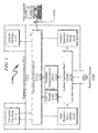
- the present invention may be summarized as depicted in the application context system block diagram of FIG. 1 (0100).
- the system is configured to communicate with a host computer system (HCS) (0101) via a wired or wireless communication link (0102) and detect radiation from a radiation source (0103).
- HCS host computer system
- the system as depicted is enclosed in a radiation camera enclosure (RCE) (0111) which may be optionally articulated via a horizontal pan rotor/motor (HPM) (0112) and/or a vertical tilting rotor/motor (VTM) (0113).
- the HPM (0112) and/or VTM (0113) may be controlled by a computing control device (CCD) (0114) as directed by the HCS (0101), or in some circumstances autonomously controlled by the CCD (0114) without direction from the HCS (0101).
- CCD computing control device
- the RCE (0111) mechanically integrates major components of the system that may include a computing control device (CCD) (0114) that communicates with the HCS (0101) and coordinates activity within the system.
- the CCD (0114) receives radiation imaging data from a radiation sensor/detector (RSD) (0115) that is screened by a coded camera aperture mask (CAM) (0116) that is mounted on the RCE (0111).
- the CAM (0116) may be rotated by a mask rotation motor (MRM) (0117) and contains rotation indicia that may be inspected by a rotation detection sensor (RDS) (0118) that senses the angle at which the CAM (0116) has been rotated by the MRM (0117).
- MRM mask rotation motor
- RDS rotation detection sensor
- the MRM (0117) may be controlled by the CCD (0114) and the angular position of the CAM (0116) determined by the RDS (0118) may be read by the CCD (0114). Via communication with the HCS (0101), the CCD (0114) may activate the MRM (0117) to angularly position the CAM (0116) and verify this position by inspection of angular position readings from the RDS (0118).
- the system is configured to permit a variety of CAM (0116) masking apertures to be affixed to the RCE (0111) for the purposes of radiation imaging operations by the RSD (0115).
- the CAM (0116) includes coded identification indicia (CII) that may be read by a CAM ID reader (CIR) (0119).
- CII coded identification indicia
- CIR CAM ID reader
- the CII read from the CAM (0116) may be transmitted to the CCD (0114) via the CIR (0119) and communicated to the HCS (0101) via the wired/wireless communication link (0102).
- the HCS (0101) may both determine the type of CAM (0116) installed in the radiation camera but also properly interpret the radiation imaging data retrieved from the RSD (0115) based on the angular rotation of the CAM (0116) based on activation of the MRM (0117) as determined by the RDS (0118).
- the CAM (0116) masking apertures may be configured to support a variety of data collection modes including "masking” and "anti-masking” so that activation of the MRM (0117) may position each of these positional modes for radiation imaging operations. While these positions are typically orthogonal to each other, there may be situations in which these two positions may be at angles other than 90-degrees from each other.
- FIG. 2 Associated with the exemplary system overview described in FIG. 1 (0100) is a radiation camera method as depicted in FIG. 2 (0200) that comprises the following steps:
- the radiation sensor/detector may be integrated in a CMOS integrated circuit.
- This CMOS integrated circuit may also incorporate in some preferred embodiments a photo camera imaging sensor (CIS) that is sensitive to ambient light.
- CIS photo camera imaging sensor
- This combination permits both radiation sensor imaging information and visual light imaging information to be simultaneously collected and transmitted by the computing control device (CCD) to a host computer system (HCS) via wired or wireless digital communication medium (DCM).
- a separate CIS may be utilized to capture the scene associated with the RSD imaging measurement. In either example, the CIS data may be forwarded to the CCD and onto the HCS for viewing and archival purposes.
- the present invention is designed to be compact (with some preferred embodiments less than 9 x 9 x 17 cm), lightweight (with some preferred embodiments less than 2.3kg), waterproof, and dust-proof.
- the system as depicted is generally protected against unpredictable vibrations, shocks, and inadvertent dropping.
- the exemplary embodiment as depicted is easy to clean (especially in the cases of unwanted radioactive contamination) and incorporates a microcontroller (CCD) board and associated hardware electronics (CPU unit, internal memory, clock generator, flash disk, and several I/O peripherals), and embedded software stored on a computer readable medium.
- CCD microcontroller
- FIG. 5 (0500) - FIG. 8 (0800) depict the outer top, bottom, front, back, right side, and left side views of an exemplary system embodiment.
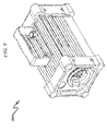
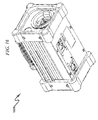
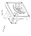
- FIG. 9 (0900) - FIG. 16 (1600) provide perspective views of a typical outer RCE containment enclosure and typical placement of major system components that interface outside of the RCE.
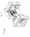
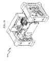
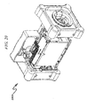
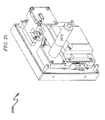
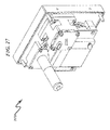
- FIG. 17 1700) - FIG. 24 (2400) provide more detail as to subsystem component placement internal to the outer shell of the RCE.
- the system incorporates a camera aperture mask (CAM) (0501) retained by a modular plastic holder (MPH) (0502) and may incorporate a photo camera (0503) to capture images of the area being monitored by the radiation sensor behind the CAM (0501).
- CAM camera aperture mask
- MPH modular plastic holder
- the system may be configured with a power indicator (0601), battery status indicator (0602), and a variety of external interfaces (0603, 0604, 0605, 0606) to support camera movement, flash, and other accessories.
- Communication with the host computer system is accomplished via wireless antenna link (0607) or wired Ethernet interface (0608) that may have corresponding link connection status indicators (0609).
- the CAM optimally comprises an aperture mask contained in a modular plastic holder (MPH).
- MPH modular plastic holder
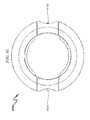
- the MPH may have many forms, but a preferred exemplary embodiment is depicted in views of FIG. 41 (4100) - FIG. 48 (4800). As depicted, the MPH has several useful attributes:
- the present invention may incorporate a wide variety of front panel wall structures to mechanically couple the RSD to the RCE.
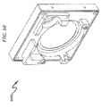
- One exemplary front panel wall structure is depicted in the front and back views illustrated in FIG. 57 (5700) - FIG. 60 (6000).
- the depicted embodiment incorporates a photography (photo image) capture window (5701) and a RSD capture window (5702) in which the CAM is positioned for rotation.
- the internal surface of the RSD capture window (5703) optimally contains an integrated ball bearing support for the CAM within the MPH.
- an exemplary invention embodiment operates as follows. First, a camera aperture mask (CAM) (typically retained by a modular plastic holder (MPH) as depicted in FIG. 41 (4100) - FIG. 48 (4800) is installed in the camera aperture.
- CAM camera aperture mask
- MPH modular plastic holder
- the operator need only to press the clip lock mechanism of the MPH as depicted in FIG. 41 (4100) and follow the orientation of the corresponding mounting groove with that of the raised guide on the camera integrated ball bearing support as depicted in FIG. 57 (5700). Once the clip lock mechanism is released, the CAM within its MPH remains conveniently fixed within the camera integrated ball bearing support.
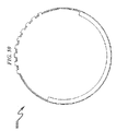
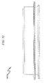
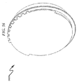
- the CAM is uniquely identified by placing a plurality (typically up to nine) of small magnet inserts (4002) / (4801) on the back side of the MPH as depicted in FIG. 40 (4000) / FIG. 48 (4800), and directly machine a corresponding number of uniform square edges (3902) on the associated ball bearing support as depicted in FIG. 39 (3900). It can be shown in FIG. 13 (1300) that the positions of both magnet inserts and square edges are continuously controlled with the Hall-effect reader and optical sensor respectively.
- FIG. 61 (6100) and FIG. 62 (6200).
- FIG. 61 6100
- FIG. 62 6200
- a logic value '1' is assigned if a magnet is detected by the Hall-effect reader during these time intervals, but if there is no detection of magnets, the quoted logic value is '0'.
- the resulting sequence of these two logical values allows establishing the CAM digital code. This means that it is necessary to rotate the CAM in use from "mask” to "anti-mask” positions to fully read its digital code.
- all but the last magnetic insert positions are filled or not filled with magnets and used for mask identification. In contrast, the last magnetic insert (which is always filled with a magnet) may normally serve to indicate the "anti-mask” position.
- the code for the aperture mask may be arbitrarily chosen, but in the example provided in FIG. 61 (6100), the code is depicted as being a byte (8 bits) in length and having a binary value corresponding to decimal 13, indicating a rank 13 aperture mask.
- the aperture mask rank and thickness may be encoded in these magnetic indicators in a variety of functionally equivalent methods, and that the bit length of the code may vary based on a wide variety of application context factors.
- the CAM utilizes a series of square edges around the periphery of the CAM to detect the CAM rotational position using an optical sensor.
- Other equivalent modes of rotational detection may be utilized without departing from the spirit and scope of the invention.
- holes within the CAM may be used for rotation sensing purposes, additional hall sensors may be used for rotation sensing, or other forms of optical recognition may be used in this circumstance.
- One skilled in the art will recognize that the embodiment depicted herein is exemplary and that other forms of rotational sensing may be utilized in this application.
- FIG. 62 depicts the CAM of FIG. 61 (6100) wherein the CAM is rotated from MASK to ANTI-MASK positions and along this rotational path (comprising identified CAM positions 0-9), each of the 8 bits of the CAM coded identification indicia (CII) are read along the rotational path by using the optical sensor to generate the digital clock necessary for sampling the Hall-effect sensor output.
- the least significant bit (LSB) of the CII is read first and the most significant bit (MSB) of the CII is read last, after which the anti-mask CII is indicated.
- LSB least significant bit
- MSB most significant bit
- the present invention allows the use of various coded camera aperture masks (CAMs) that provide for a direct background noise subtraction by means of a procedure called mask/anti-mask. This procedure greatly contributes to the reduced size and weight of the present invention regarding existing methods of manual camera masking and thus reduces the need to shield the radiation sensor/detector.
- the CAMs may be generally designed by CEA LIST (see and included by reference: M. Gmar, M. Agelou, F. Carrel and V. Schoepff, "GAMPIX: A New Generation Of Gamma Camera", Nucl. Instrum. Methods Phys. Res. A, Vol. 652, pp.
- three coded aperture masks containing a binary array or pattern of open and closed circular cells and uniformly distributed under a particular sequence are considered as optimal in many preferred invention embodiments:
- the embodiments of the present invention camera system may often be used in extreme conditions with high radiation levels. Therefore, considering the ALARA principle regarding personal dosimetry, the present invention represents a compact plug-and-play instrument capable of quickly changing the CAMs in order to prevent unnecessary radiation exposures to the camera operator.
- FIG. 64 A typical system application context depicting accessories that may be connected to the radiation camera system is depicted in FIG. 64 (6400). Not illustrated in this diagram are keyboard and status indicators as well as power supply components and support for portable battery operation, as these components are well known to those in the electrical arts.
- a preferred exemplary invention feature list may include the following attributes as integrated within a deployable plug-and-play and remotely controlled radiation camera:
- the present invention anticipates that some preferred embodiments may be configured to include external devices or accessories such as a WIFI antenna, flash-lamp, dose rate probe, battery charger, laser telemeter, etc.
- external devices or accessories such as a WIFI antenna, flash-lamp, dose rate probe, battery charger, laser telemeter, etc.
- the present invention anticipates that some preferred embodiments may be configured to automatically estimate and adapt mask/anti-mask rotation periods according to measurement environment (measured radiation source strength and background radiation detected by the radiation sensor/detector) in order to minimize the number of mask rotations and optimize the time to obtain a meaningful image.
- the present invention anticipates that some preferred embodiments may be configured to automatically estimate and adapt the appropriate radiation sensor/detector shutter frame time according to measurement environment (radiation source strength and background radiation detected by the radiation sensor/detector) in order to display a meaningful image in the minimum amount of time.
- the present invention anticipates that some preferred embodiments may be configured to automatically perform historical data analysis on data retrieved from the radiation sensor/detector on a frame-by-frame basis. This allows a dynamic follow-up of the hotspot localization evolution as well as an historical saving of the whole gamma imaging analysis results. The user can go back or forward to a specific frame for comparison purposes or to eliminate possible radiation measurement artifacts.
- the present invention anticipates that some preferred embodiments may be configured to automatically estimate the radiation dose at the same location of the measured radioactive hotspot if the distance between this location and the measurement point is provided by the user.
- This radiation dose may be directly estimated by connecting an external laser telemeter to the camera.
- the present invention anticipates that some preferred embodiments may be configured to directly measure radiation dosing information by connecting an external dose rate meter to the camera.
- This alternate embodiment configuration permits the corresponding ambient dose equivalent rate measured at the same camera location can be used for any of the following:
- the present invention anticipates that some preferred embodiments may be configured to integrate an external flash-lamp option to be able to automatically frame and take pictures of the camera field-of-view scene of interest, even in the worst illumination conditions.
- the present invention anticipates that some preferred embodiments may be configured to integrate an external imaging camera or video monitor to be able to automatically frame and take pictures of the visual camera field-of-view scene of interest associated with the radiation sensor/detector.
- the present invention anticipates the use of a variety of sensors associated with the camera to provide for measurement traceability. These include but are not limited to the following types of sensors:
- the incorporation of a 3-axis accelerometer in the system can provide information about possible camera movements during measurements.
- the incorporation of a 3-axis magnetometer in the system can provide information about the hotspot direction relative to the terrestrial magnetic north.
- the incorporation of a 3-axis magnetometer in the system can be used to control the internal temperature of the camera.
- the HCS may communicate with the CCD using a variety of protocols and command structures, but a preferred exemplary command set is provided in the following table that illustrates command identifications, the functions performed by the CCD, the applicable devices for the command, and the data type value used in the command.
- the present invention operates to provide several advantages over the prior art.
- existing radiation cameras including gamma radiation cameras
- This requires manual installation of aperture masks, manual rotation of the aperture mask, manual positioning of the camera, and manual collection of data. All of these manual operations increase the exposure time in the field-of-view of the radiation source and thus increase the risk of radiation dose for the operator.
- the prior art imposes several constraints while guaranteeing the radiation protection of the persons manipulating such instruments.
- the present invention provides an automatic remotely controlled radiation camera that improves the reduction in operator exposure time with the well-known ALARA principles relating to ionizing radiation exposure of the operators during measurements.
- the present invention preferred exemplary system embodiment anticipates a wide variety of variations in the basic theme of construction, but can be generalized as a radiation camera system comprising:
- the present invention preferred exemplary method embodiment anticipates a wide variety of variations in the basic theme of implementation, but can be generalized as a radiation camera method, the method operating in conjunction with a radiation camera system comprising:
- the present invention anticipates a wide variety of variations in the basic theme of construction.
- the examples presented previously do not represent the entire scope of possible usages. They are meant to cite a few of the almost limitless possibilities.
- This basic system and method may be augmented with a variety of ancillary embodiments, including but not limited to:
- the present invention may be implemented as a computer program product for use with a computerized computing system.
- programs defining the functions defined by the present invention can be written in any appropriate programming language and delivered to a computer in many forms, including but not limited to: (a) information permanently stored on non-writeable storage media (e.g., read-only memory devices such as ROMs or CD-ROM disks); (b) information alterably stored on writeable storage media (e.g., hard disks and USB thumb drives); and/or (c) information conveyed to a computer through communication media, such as a local area network, a telephone network, or a public network such as the Internet.
- non-writeable storage media e.g., read-only memory devices such as ROMs or CD-ROM disks
- writeable storage media e.g., hard disks and USB thumb drives
- information conveyed to a computer through communication media such as a local area network, a telephone network, or a public network such as the Internet.
- the present invention system embodiments can incorporate a variety of computer readable media that comprise computer usable medium having computer readable code means embodied therein.
- One skilled in the art will recognize that the software associated with the various processes described herein can be embodied in a wide variety of computer accessible media from which the software is loaded and activated.
- the software associated with the various processes described herein can be embodied in a wide variety of computer accessible media from which the software is loaded and activated.
- the present invention anticipates and includes this type of computer readable media within the scope of the invention.
- Pursuant to In re Nuijten, 500 F.3d 1346 ( Fed. Cir. 2007 ) U.S. Patent Application S/N 09/211,928
- the present invention scope is limited to computer readable media wherein the media is both tangible and non-transitory.
- a radiation camera system and method incorporating a radiation sensor/detector (RSD) and automated operation of coded camera aperture masks (CAMs) is disclosed that may be advantageously applied to real-time tracking of radiological hot spots in crisis, maintenance, decontamination, and/or maintenance scenarios.
- the system/method integrates automated camera RSD positioning, CAM identification, and CAM rotation.
- the system incorporates computerized controls in conjunction with remotely controlled horizontal/vertical tilting motors to direct the RSD aperture position and view of the RSD.
- CAMs may be installed in the camera manually and are automatically identified by the system via the use of encoding magnets that are detected using a Hall-effect sensor.
- the CAMs may be rotated after installation in the camera by computer control to predefined positions such as "mask” and "anti-mask” to affect the desired degree of radiation screening to be applied to the RSD.
Landscapes
- Physics & Mathematics (AREA)
- Health & Medical Sciences (AREA)
- Life Sciences & Earth Sciences (AREA)
- General Physics & Mathematics (AREA)
- High Energy & Nuclear Physics (AREA)
- Molecular Biology (AREA)
- Spectroscopy & Molecular Physics (AREA)
- Studio Devices (AREA)
Applications Claiming Priority (2)
| Application Number | Priority Date | Filing Date | Title |
|---|---|---|---|
| FR1401205A FR3021487B3 (fr) | 2014-05-26 | 2014-05-26 | Systeme et procede de camera pour radiations |
| US14/547,990 US9547093B2 (en) | 2014-05-26 | 2014-11-19 | Radiation camera system and method |
Publications (2)
| Publication Number | Publication Date |
|---|---|
| EP2952933A1 true EP2952933A1 (fr) | 2015-12-09 |
| EP2952933B1 EP2952933B1 (fr) | 2019-07-17 |
Family
ID=53682435
Family Applications (1)
| Application Number | Title | Priority Date | Filing Date |
|---|---|---|---|
| EP15162056.4A Active EP2952933B1 (fr) | 2014-05-26 | 2015-03-31 | Système et procédé de caméra à rayonnement |
Country Status (1)
| Country | Link |
|---|---|
| EP (1) | EP2952933B1 (fr) |
Citations (4)
| Publication number | Priority date | Publication date | Assignee | Title |
|---|---|---|---|---|
| US4595014A (en) * | 1983-10-18 | 1986-06-17 | University Patents, Inc. | Imaging probe and method |
| US5606165A (en) * | 1993-11-19 | 1997-02-25 | Ail Systems Inc. | Square anti-symmetric uniformly redundant array coded aperture imaging system |
| US5710578A (en) | 1987-12-09 | 1998-01-20 | International Business Machines Corporation | Computer program product for utilizing fast polygon fill routines in a graphics display system |
| US20060108509A1 (en) * | 2004-09-09 | 2006-05-25 | Frangioni John V | Systems and methods for multi-modal imaging |
-
2015
- 2015-03-31 EP EP15162056.4A patent/EP2952933B1/fr active Active
Patent Citations (4)
| Publication number | Priority date | Publication date | Assignee | Title |
|---|---|---|---|---|
| US4595014A (en) * | 1983-10-18 | 1986-06-17 | University Patents, Inc. | Imaging probe and method |
| US5710578A (en) | 1987-12-09 | 1998-01-20 | International Business Machines Corporation | Computer program product for utilizing fast polygon fill routines in a graphics display system |
| US5606165A (en) * | 1993-11-19 | 1997-02-25 | Ail Systems Inc. | Square anti-symmetric uniformly redundant array coded aperture imaging system |
| US20060108509A1 (en) * | 2004-09-09 | 2006-05-25 | Frangioni John V | Systems and methods for multi-modal imaging |
Non-Patent Citations (4)
| Title |
|---|
| AMGAROU KHALIL ET AL: "Evaluation of the next generation gamma imager", 2013 3RD INTERNATIONAL CONFERENCE ON ADVANCEMENTS IN NUCLEAR INSTRUMENTATION, MEASUREMENT METHODS AND THEIR APPLICATIONS (ANIMMA), IEEE, 23 June 2013 (2013-06-23), pages 1 - 6, XP032560838, DOI: 10.1109/ANIMMA.2013.6728051 * |
| DURRANT P T ET AL: "The application of pinhole and coded aperture imaging in the nuclear environment", NUCLEAR INSTRUMENTS & METHODS IN PHYSICS RESEARCH. SECTION A: ACCELERATORS, SPECTROMETERS, DETECTORS, AND ASSOCIATED EQUIPMENT, ELSEVIER BV * NORTH-HOLLAND, NL, vol. 422, no. 1-3, 11 February 1999 (1999-02-11), pages 667 - 671, XP004161916, ISSN: 0168-9002, DOI: 10.1016/S0168-9002(98)01014-6 * |
| M. GMAR; M. AGELOU; F. CARREL; V. SCHOEPFF: "GAMPIX: A New Generation Of Gamma Camera", NUCL. INSTRUM. METHODS PHYS. RES. A, vol. 652, 2011, pages 638 - 640, XP028291717, DOI: doi:10.1016/j.nima.2010.09.003 |
| S.R. GOTTESMAN; E.E. FENIMORE: "New Family Of Binary Arrays For Coded Aperture Imaging", APPL. OPTICS, vol. 28, 1989, pages 4344 - 4352 |
Also Published As
| Publication number | Publication date |
|---|---|
| EP2952933B1 (fr) | 2019-07-17 |
Similar Documents
| Publication | Publication Date | Title |
|---|---|---|
| CN101778598B (zh) | 医学系统中的运动检测 | |
| EP3351176B1 (fr) | Appareil d'imagerie à rayons x et son procédé de commande | |
| US7242005B2 (en) | Radiation detecting cassette and radiation image data management system | |
| KR20130121828A (ko) | 방향성 방사선 검출 장치 및 역 콜리메이션을 사용하는 방법 | |
| US9547093B2 (en) | Radiation camera system and method | |
| JP2003248060A (ja) | 放射線画像撮影装置 | |
| WO2013036654A1 (fr) | Procédé et système d'association de dispositifs présentant une zone de couverture pour un appareil photographique | |
| CN111096759A (zh) | X射线摄影系统及其平板探测器、相关方法 | |
| Boudergui et al. | Development of a drone equipped with optimized sensors for nuclear and radiological risk characterization | |
| US10722198B2 (en) | Portable radiological cassette comprising patient identification means | |
| KR102557945B1 (ko) | 엑스선 디텍터 및 그 제어 방법 | |
| US20130173221A1 (en) | Radiation sensor system | |
| US7465925B2 (en) | Personal radiation detector and method of operation of same | |
| EP2952933B1 (fr) | Système et procédé de caméra à rayonnement | |
| JP5509558B2 (ja) | 放射線画像撮影システム | |
| CN117388901A (zh) | 一种电子个人剂量计、核电站门禁控制系统 | |
| US20240164732A1 (en) | Intraoperative radiation probe system with radiation-orientation mapping | |
| JP7096449B1 (ja) | 存在検出のための1つ以上のパラメータを決定するための可視光信号の使用 | |
| JP2009183562A (ja) | 放射線画像撮影システム | |
| KR101896802B1 (ko) | 논리회로가 적용된 디지털 출력을 갖는 이미지 센서 모듈을 이용한 라돈 검출 시스템 및 검출방법 | |
| EP1865338A2 (fr) | Détecteur de radiation personnel et procédé de fonctionnement d'un détecteur de radiation personnel | |
| JP5786995B2 (ja) | 放射線画像撮影システム | |
| Craig et al. | ARG-US Remote Area Modular Monitoring: Digital Cameras for Enhancing Safety and Security | |
| US20220401055A1 (en) | Image acquisition with multiple detectors | |
| KR101551636B1 (ko) | 엑스레이 시스템의 시각 표시 장치 및 동기화 장치 |
Legal Events
| Date | Code | Title | Description |
|---|---|---|---|
| PUAI | Public reference made under article 153(3) epc to a published international application that has entered the european phase |
Free format text: ORIGINAL CODE: 0009012 |
|
| AK | Designated contracting states |
Kind code of ref document: A1 Designated state(s): AL AT BE BG CH CY CZ DE DK EE ES FI FR GB GR HR HU IE IS IT LI LT LU LV MC MK MT NL NO PL PT RO RS SE SI SK SM TR |
|
| AX | Request for extension of the european patent |
Extension state: BA ME |
|
| 17P | Request for examination filed |
Effective date: 20160609 |
|
| RBV | Designated contracting states (corrected) |
Designated state(s): AL AT BE BG CH CY CZ DE DK EE ES FI FR GB GR HR HU IE IS IT LI LT LU LV MC MK MT NL NO PL PT RO RS SE SI SK SM TR |
|
| STAA | Information on the status of an ep patent application or granted ep patent |
Free format text: STATUS: EXAMINATION IS IN PROGRESS |
|
| 17Q | First examination report despatched |
Effective date: 20180307 |
|
| GRAP | Despatch of communication of intention to grant a patent |
Free format text: ORIGINAL CODE: EPIDOSNIGR1 |
|
| STAA | Information on the status of an ep patent application or granted ep patent |
Free format text: STATUS: GRANT OF PATENT IS INTENDED |
|
| INTG | Intention to grant announced |
Effective date: 20190207 |
|
| GRAS | Grant fee paid |
Free format text: ORIGINAL CODE: EPIDOSNIGR3 |
|
| GRAA | (expected) grant |
Free format text: ORIGINAL CODE: 0009210 |
|
| STAA | Information on the status of an ep patent application or granted ep patent |
Free format text: STATUS: THE PATENT HAS BEEN GRANTED |
|
| AK | Designated contracting states |
Kind code of ref document: B1 Designated state(s): AL AT BE BG CH CY CZ DE DK EE ES FI FR GB GR HR HU IE IS IT LI LT LU LV MC MK MT NL NO PL PT RO RS SE SI SK SM TR |
|
| RAP1 | Party data changed (applicant data changed or rights of an application transferred) |
Owner name: MIRION TECHNOLOGIES (CANBERRA ) SAS |
|
| REG | Reference to a national code |
Ref country code: GB Ref legal event code: FG4D |
|
| REG | Reference to a national code |
Ref country code: CH Ref legal event code: EP |
|
| REG | Reference to a national code |
Ref country code: IE Ref legal event code: FG4D |
|
| REG | Reference to a national code |
Ref country code: DE Ref legal event code: R096 Ref document number: 602015033808 Country of ref document: DE |
|
| REG | Reference to a national code |
Ref country code: AT Ref legal event code: REF Ref document number: 1156360 Country of ref document: AT Kind code of ref document: T Effective date: 20190815 |
|
| REG | Reference to a national code |
Ref country code: NL Ref legal event code: MP Effective date: 20190717 |
|
| REG | Reference to a national code |
Ref country code: LT Ref legal event code: MG4D |
|
| REG | Reference to a national code |
Ref country code: AT Ref legal event code: MK05 Ref document number: 1156360 Country of ref document: AT Kind code of ref document: T Effective date: 20190717 |
|
| PG25 | Lapsed in a contracting state [announced via postgrant information from national office to epo] |
Ref country code: FI Free format text: LAPSE BECAUSE OF FAILURE TO SUBMIT A TRANSLATION OF THE DESCRIPTION OR TO PAY THE FEE WITHIN THE PRESCRIBED TIME-LIMIT Effective date: 20190717 Ref country code: NO Free format text: LAPSE BECAUSE OF FAILURE TO SUBMIT A TRANSLATION OF THE DESCRIPTION OR TO PAY THE FEE WITHIN THE PRESCRIBED TIME-LIMIT Effective date: 20191017 Ref country code: AT Free format text: LAPSE BECAUSE OF FAILURE TO SUBMIT A TRANSLATION OF THE DESCRIPTION OR TO PAY THE FEE WITHIN THE PRESCRIBED TIME-LIMIT Effective date: 20190717 Ref country code: NL Free format text: LAPSE BECAUSE OF FAILURE TO SUBMIT A TRANSLATION OF THE DESCRIPTION OR TO PAY THE FEE WITHIN THE PRESCRIBED TIME-LIMIT Effective date: 20190717 Ref country code: SE Free format text: LAPSE BECAUSE OF FAILURE TO SUBMIT A TRANSLATION OF THE DESCRIPTION OR TO PAY THE FEE WITHIN THE PRESCRIBED TIME-LIMIT Effective date: 20190717 Ref country code: BG Free format text: LAPSE BECAUSE OF FAILURE TO SUBMIT A TRANSLATION OF THE DESCRIPTION OR TO PAY THE FEE WITHIN THE PRESCRIBED TIME-LIMIT Effective date: 20191017 Ref country code: PT Free format text: LAPSE BECAUSE OF FAILURE TO SUBMIT A TRANSLATION OF THE DESCRIPTION OR TO PAY THE FEE WITHIN THE PRESCRIBED TIME-LIMIT Effective date: 20191118 Ref country code: HR Free format text: LAPSE BECAUSE OF FAILURE TO SUBMIT A TRANSLATION OF THE DESCRIPTION OR TO PAY THE FEE WITHIN THE PRESCRIBED TIME-LIMIT Effective date: 20190717 Ref country code: LT Free format text: LAPSE BECAUSE OF FAILURE TO SUBMIT A TRANSLATION OF THE DESCRIPTION OR TO PAY THE FEE WITHIN THE PRESCRIBED TIME-LIMIT Effective date: 20190717 |
|
| PG25 | Lapsed in a contracting state [announced via postgrant information from national office to epo] |
Ref country code: AL Free format text: LAPSE BECAUSE OF FAILURE TO SUBMIT A TRANSLATION OF THE DESCRIPTION OR TO PAY THE FEE WITHIN THE PRESCRIBED TIME-LIMIT Effective date: 20190717 Ref country code: LV Free format text: LAPSE BECAUSE OF FAILURE TO SUBMIT A TRANSLATION OF THE DESCRIPTION OR TO PAY THE FEE WITHIN THE PRESCRIBED TIME-LIMIT Effective date: 20190717 Ref country code: GR Free format text: LAPSE BECAUSE OF FAILURE TO SUBMIT A TRANSLATION OF THE DESCRIPTION OR TO PAY THE FEE WITHIN THE PRESCRIBED TIME-LIMIT Effective date: 20191018 Ref country code: IS Free format text: LAPSE BECAUSE OF FAILURE TO SUBMIT A TRANSLATION OF THE DESCRIPTION OR TO PAY THE FEE WITHIN THE PRESCRIBED TIME-LIMIT Effective date: 20191117 Ref country code: RS Free format text: LAPSE BECAUSE OF FAILURE TO SUBMIT A TRANSLATION OF THE DESCRIPTION OR TO PAY THE FEE WITHIN THE PRESCRIBED TIME-LIMIT Effective date: 20190717 Ref country code: ES Free format text: LAPSE BECAUSE OF FAILURE TO SUBMIT A TRANSLATION OF THE DESCRIPTION OR TO PAY THE FEE WITHIN THE PRESCRIBED TIME-LIMIT Effective date: 20190717 |
|
| PG25 | Lapsed in a contracting state [announced via postgrant information from national office to epo] |
Ref country code: TR Free format text: LAPSE BECAUSE OF FAILURE TO SUBMIT A TRANSLATION OF THE DESCRIPTION OR TO PAY THE FEE WITHIN THE PRESCRIBED TIME-LIMIT Effective date: 20190717 |
|
| PG25 | Lapsed in a contracting state [announced via postgrant information from national office to epo] |
Ref country code: RO Free format text: LAPSE BECAUSE OF FAILURE TO SUBMIT A TRANSLATION OF THE DESCRIPTION OR TO PAY THE FEE WITHIN THE PRESCRIBED TIME-LIMIT Effective date: 20190717 Ref country code: PL Free format text: LAPSE BECAUSE OF FAILURE TO SUBMIT A TRANSLATION OF THE DESCRIPTION OR TO PAY THE FEE WITHIN THE PRESCRIBED TIME-LIMIT Effective date: 20190717 Ref country code: DK Free format text: LAPSE BECAUSE OF FAILURE TO SUBMIT A TRANSLATION OF THE DESCRIPTION OR TO PAY THE FEE WITHIN THE PRESCRIBED TIME-LIMIT Effective date: 20190717 Ref country code: IT Free format text: LAPSE BECAUSE OF FAILURE TO SUBMIT A TRANSLATION OF THE DESCRIPTION OR TO PAY THE FEE WITHIN THE PRESCRIBED TIME-LIMIT Effective date: 20190717 Ref country code: EE Free format text: LAPSE BECAUSE OF FAILURE TO SUBMIT A TRANSLATION OF THE DESCRIPTION OR TO PAY THE FEE WITHIN THE PRESCRIBED TIME-LIMIT Effective date: 20190717 |
|
| PG25 | Lapsed in a contracting state [announced via postgrant information from national office to epo] |
Ref country code: CZ Free format text: LAPSE BECAUSE OF FAILURE TO SUBMIT A TRANSLATION OF THE DESCRIPTION OR TO PAY THE FEE WITHIN THE PRESCRIBED TIME-LIMIT Effective date: 20190717 Ref country code: IS Free format text: LAPSE BECAUSE OF FAILURE TO SUBMIT A TRANSLATION OF THE DESCRIPTION OR TO PAY THE FEE WITHIN THE PRESCRIBED TIME-LIMIT Effective date: 20200224 Ref country code: SM Free format text: LAPSE BECAUSE OF FAILURE TO SUBMIT A TRANSLATION OF THE DESCRIPTION OR TO PAY THE FEE WITHIN THE PRESCRIBED TIME-LIMIT Effective date: 20190717 Ref country code: SK Free format text: LAPSE BECAUSE OF FAILURE TO SUBMIT A TRANSLATION OF THE DESCRIPTION OR TO PAY THE FEE WITHIN THE PRESCRIBED TIME-LIMIT Effective date: 20190717 |
|
| REG | Reference to a national code |
Ref country code: DE Ref legal event code: R097 Ref document number: 602015033808 Country of ref document: DE |
|
| PLBE | No opposition filed within time limit |
Free format text: ORIGINAL CODE: 0009261 |
|
| STAA | Information on the status of an ep patent application or granted ep patent |
Free format text: STATUS: NO OPPOSITION FILED WITHIN TIME LIMIT |
|
| PG2D | Information on lapse in contracting state deleted |
Ref country code: IS |
|
| 26N | No opposition filed |
Effective date: 20200603 |
|
| PG25 | Lapsed in a contracting state [announced via postgrant information from national office to epo] |
Ref country code: SI Free format text: LAPSE BECAUSE OF FAILURE TO SUBMIT A TRANSLATION OF THE DESCRIPTION OR TO PAY THE FEE WITHIN THE PRESCRIBED TIME-LIMIT Effective date: 20190717 |
|
| PG25 | Lapsed in a contracting state [announced via postgrant information from national office to epo] |
Ref country code: MC Free format text: LAPSE BECAUSE OF FAILURE TO SUBMIT A TRANSLATION OF THE DESCRIPTION OR TO PAY THE FEE WITHIN THE PRESCRIBED TIME-LIMIT Effective date: 20190717 |
|
| REG | Reference to a national code |
Ref country code: CH Ref legal event code: PL |
|
| REG | Reference to a national code |
Ref country code: BE Ref legal event code: MM Effective date: 20200331 |
|
| PG25 | Lapsed in a contracting state [announced via postgrant information from national office to epo] |
Ref country code: LU Free format text: LAPSE BECAUSE OF NON-PAYMENT OF DUE FEES Effective date: 20200331 |
|
| PG25 | Lapsed in a contracting state [announced via postgrant information from national office to epo] |
Ref country code: CH Free format text: LAPSE BECAUSE OF NON-PAYMENT OF DUE FEES Effective date: 20200331 Ref country code: IE Free format text: LAPSE BECAUSE OF NON-PAYMENT OF DUE FEES Effective date: 20200331 Ref country code: LI Free format text: LAPSE BECAUSE OF NON-PAYMENT OF DUE FEES Effective date: 20200331 |
|
| PG25 | Lapsed in a contracting state [announced via postgrant information from national office to epo] |
Ref country code: BE Free format text: LAPSE BECAUSE OF NON-PAYMENT OF DUE FEES Effective date: 20200331 |
|
| PGFP | Annual fee paid to national office [announced via postgrant information from national office to epo] |
Ref country code: FR Payment date: 20210225 Year of fee payment: 7 |
|
| PGFP | Annual fee paid to national office [announced via postgrant information from national office to epo] |
Ref country code: DE Payment date: 20210316 Year of fee payment: 7 Ref country code: GB Payment date: 20210317 Year of fee payment: 7 |
|
| PG25 | Lapsed in a contracting state [announced via postgrant information from national office to epo] |
Ref country code: MT Free format text: LAPSE BECAUSE OF FAILURE TO SUBMIT A TRANSLATION OF THE DESCRIPTION OR TO PAY THE FEE WITHIN THE PRESCRIBED TIME-LIMIT Effective date: 20190717 Ref country code: CY Free format text: LAPSE BECAUSE OF FAILURE TO SUBMIT A TRANSLATION OF THE DESCRIPTION OR TO PAY THE FEE WITHIN THE PRESCRIBED TIME-LIMIT Effective date: 20190717 |
|
| PG25 | Lapsed in a contracting state [announced via postgrant information from national office to epo] |
Ref country code: MK Free format text: LAPSE BECAUSE OF FAILURE TO SUBMIT A TRANSLATION OF THE DESCRIPTION OR TO PAY THE FEE WITHIN THE PRESCRIBED TIME-LIMIT Effective date: 20190717 |
|
| REG | Reference to a national code |
Ref country code: DE Ref legal event code: R119 Ref document number: 602015033808 Country of ref document: DE |
|
| GBPC | Gb: european patent ceased through non-payment of renewal fee |
Effective date: 20220331 |
|
| PG25 | Lapsed in a contracting state [announced via postgrant information from national office to epo] |
Ref country code: GB Free format text: LAPSE BECAUSE OF NON-PAYMENT OF DUE FEES Effective date: 20220331 Ref country code: FR Free format text: LAPSE BECAUSE OF NON-PAYMENT OF DUE FEES Effective date: 20220331 Ref country code: DE Free format text: LAPSE BECAUSE OF NON-PAYMENT OF DUE FEES Effective date: 20221001 |