EP2952954A1 - Techniques d'extension de gamme dynamique pour un capteur de front d'onde comprenant une utilisation dans une mesure ophtalmique - Google Patents
Techniques d'extension de gamme dynamique pour un capteur de front d'onde comprenant une utilisation dans une mesure ophtalmique Download PDFInfo
- Publication number
- EP2952954A1 EP2952954A1 EP15175012.2A EP15175012A EP2952954A1 EP 2952954 A1 EP2952954 A1 EP 2952954A1 EP 15175012 A EP15175012 A EP 15175012A EP 2952954 A1 EP2952954 A1 EP 2952954A1
- Authority
- EP
- European Patent Office
- Prior art keywords
- eye
- light
- telescope
- retina
- wavefront sensor
- Prior art date
- Legal status (The legal status is an assumption and is not a legal conclusion. Google has not performed a legal analysis and makes no representation as to the accuracy of the status listed.)
- Withdrawn
Links
- 238000005259 measurement Methods 0.000 title claims abstract description 36
- 238000000034 method Methods 0.000 title description 18
- 210000001525 retina Anatomy 0.000 claims abstract description 40
- 230000004075 alteration Effects 0.000 claims abstract description 32
- 230000003287 optical effect Effects 0.000 claims abstract description 29
- 238000003384 imaging method Methods 0.000 claims abstract description 11
- 238000002156 mixing Methods 0.000 claims abstract description 3
- 238000012937 correction Methods 0.000 claims description 35
- 201000009310 astigmatism Diseases 0.000 claims description 9
- 238000001514 detection method Methods 0.000 claims description 6
- 238000010008 shearing Methods 0.000 claims description 4
- 238000001914 filtration Methods 0.000 claims description 2
- 208000014733 refractive error Diseases 0.000 description 10
- 210000004087 cornea Anatomy 0.000 description 6
- 230000001965 increasing effect Effects 0.000 description 6
- 239000013307 optical fiber Substances 0.000 description 5
- 230000003044 adaptive effect Effects 0.000 description 4
- 239000000835 fiber Substances 0.000 description 4
- 238000000926 separation method Methods 0.000 description 4
- 230000015556 catabolic process Effects 0.000 description 3
- 238000006731 degradation reaction Methods 0.000 description 3
- 230000004438 eyesight Effects 0.000 description 3
- 238000000053 physical method Methods 0.000 description 3
- 230000010287 polarization Effects 0.000 description 3
- 238000005070 sampling Methods 0.000 description 3
- 230000004308 accommodation Effects 0.000 description 2
- 238000013461 design Methods 0.000 description 2
- 238000003745 diagnosis Methods 0.000 description 2
- 238000005305 interferometry Methods 0.000 description 2
- 238000013507 mapping Methods 0.000 description 2
- 238000012986 modification Methods 0.000 description 2
- 230000004048 modification Effects 0.000 description 2
- 208000001491 myopia Diseases 0.000 description 2
- 210000001747 pupil Anatomy 0.000 description 2
- 230000035945 sensitivity Effects 0.000 description 2
- 238000012876 topography Methods 0.000 description 2
- 238000013519 translation Methods 0.000 description 2
- 230000004304 visual acuity Effects 0.000 description 2
- 230000000007 visual effect Effects 0.000 description 2
- 241000167857 Bourreria Species 0.000 description 1
- 238000004458 analytical method Methods 0.000 description 1
- 230000005540 biological transmission Effects 0.000 description 1
- 230000000903 blocking effect Effects 0.000 description 1
- 230000008859 change Effects 0.000 description 1
- 238000000576 coating method Methods 0.000 description 1
- 239000012141 concentrate Substances 0.000 description 1
- 238000007796 conventional method Methods 0.000 description 1
- 230000007547 defect Effects 0.000 description 1
- 230000000694 effects Effects 0.000 description 1
- 230000002708 enhancing effect Effects 0.000 description 1
- 238000002347 injection Methods 0.000 description 1
- 239000007924 injection Substances 0.000 description 1
- 230000003993 interaction Effects 0.000 description 1
- 239000004973 liquid crystal related substance Substances 0.000 description 1
- 238000012545 processing Methods 0.000 description 1
- 230000004044 response Effects 0.000 description 1
- 230000002207 retinal effect Effects 0.000 description 1
- 238000012216 screening Methods 0.000 description 1
- 239000000243 solution Substances 0.000 description 1
- 230000007480 spreading Effects 0.000 description 1
- 238000012546 transfer Methods 0.000 description 1
Images



Classifications
-
- A—HUMAN NECESSITIES
- A61—MEDICAL OR VETERINARY SCIENCE; HYGIENE
- A61B—DIAGNOSIS; SURGERY; IDENTIFICATION
- A61B3/00—Apparatus for testing the eyes; Instruments for examining the eyes
- A61B3/10—Objective types, i.e. instruments for examining the eyes independent of the patients' perceptions or reactions
- A61B3/14—Arrangements specially adapted for eye photography
-
- A—HUMAN NECESSITIES
- A61—MEDICAL OR VETERINARY SCIENCE; HYGIENE
- A61B—DIAGNOSIS; SURGERY; IDENTIFICATION
- A61B3/00—Apparatus for testing the eyes; Instruments for examining the eyes
- A61B3/10—Objective types, i.e. instruments for examining the eyes independent of the patients' perceptions or reactions
- A61B3/103—Objective types, i.e. instruments for examining the eyes independent of the patients' perceptions or reactions for determining refraction, e.g. refractometers, skiascopes
-
- A—HUMAN NECESSITIES
- A61—MEDICAL OR VETERINARY SCIENCE; HYGIENE
- A61B—DIAGNOSIS; SURGERY; IDENTIFICATION
- A61B3/00—Apparatus for testing the eyes; Instruments for examining the eyes
- A61B3/10—Objective types, i.e. instruments for examining the eyes independent of the patients' perceptions or reactions
- A61B3/14—Arrangements specially adapted for eye photography
- A61B3/15—Arrangements specially adapted for eye photography with means for aligning, spacing or blocking spurious reflection ; with means for relaxing
- A61B3/156—Arrangements specially adapted for eye photography with means for aligning, spacing or blocking spurious reflection ; with means for relaxing for blocking
- A61B3/158—Arrangements specially adapted for eye photography with means for aligning, spacing or blocking spurious reflection ; with means for relaxing for blocking of corneal reflection
-
- G—PHYSICS
- G02—OPTICS
- G02C—SPECTACLES; SUNGLASSES OR GOGGLES INSOFAR AS THEY HAVE THE SAME FEATURES AS SPECTACLES; CONTACT LENSES
- G02C7/00—Optical parts
- G02C7/02—Lenses; Lens systems ; Methods of designing lenses
- G02C7/024—Methods of designing ophthalmic lenses
- G02C7/027—Methods of designing ophthalmic lenses considering wearer's parameters
Definitions
- the present invention is directed to measurement of the refractive error in the eye, more particularly to methods and techniques for compiling a topographic mapping of these refractive errors.
- Measurements of aberrations in an eye are important for diagnosis of visual defects and assessment of acuity. These measurements and their accuracy become increasingly important in light of the growing number of ways, both surgical and non-surgical, that aberrations can be corrected. These corrections rely on accurate, precise measurements of the entire ocular system, allowing successful screening, treatment and follow-up. Enhancements in the accuracy of ocular measurements may aid in improving the identification of patients in need of correction and the performance of the correction itself.
- objective methods for assessing the performance of the ocular system.
- Such objective methods include corneal topography, wavefront aberrometry, corneal interferometry, and auto-refraction. Many of these methods only measure the contribution of specific elements to the total refractive error. For example, much work has been directed to measuring the topography of the cornea and characterizing the corneal layer. However, the corneal shape only contributes about 30-40% of the total refractive error in most cases. In order to measure the bulk of the refractive error and to provide a complete mapping for diagnosis and correction, additional information and measurements are needed.
- auto-refraction Another method for determining the refraction of the eye is auto-refraction, which uses a variety of techniques to automatically determine the required corrective prescription. These automated techniques include projecting one or more spots or patterns onto the retina, automatically adjusting optical elements in the auto-refractor until the desired response is achieved, and determining the required correction from this adjustment.
- auto-refractors are not considered especially reliable. Further, auto-refractors measure only lower order components of the aberrations, e.g., focus and astigmatic errors.
- Wavefront aberrometry measures the full, end-to-end aberrations through the entire optics of the eye.
- a spot is projected onto the retina, and the resulting returned light is measured with an optical system, thus obtaining a full, integrated, line-of-sight measurement of the eye's aberrations.
- a key limitation of the instruments used in these measurements is the total resolution, which is ultimately limited by the lenslet array of the instrument.
- selection of the lenslet array is itself limited by several factors, most importantly the size of the spot projected onto the retina.
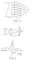
- FIG. 2 A schematic illustration of the basic elements of a two dimensional embodiment of a Shack-Hartmann wavefront sensor is shown in Figure 2 .
- a portion of an incoming wavefront 110 from the retina is incident on a two-dimensional lenslet array 112.
- the lenslet array 112 dissects the incoming wavefront 110 into a number of small samples.
- the smaller the lenslet the higher the spatial resolution of the sensor.
- the spot size from small the lenslet due to diffraction effects, limits the focal length that may be used, which in turn leads to lower sensitivity.
- these two parameters must be balanced in accordance with desired measurement performance.
- the image on the detector plane 114 consists of a pattern of focal spots 116 with regular spacing d created with lenslets 112 of focal length f, as shown in Figures 3 .
- These spots must be distinct and separate, i.e., they must be readily identifiable.
- the spot size ⁇ cannot exceed 1 ⁇ 2 of the separation of the spots.
- the dynamic range is directly proportional to the separation parameter and the lenslet size.
- a particularly useful arrangement for a Shack-Hartmann wavefront sensor ocular measuring system places the lenslet array in an image relay optical system at a plane conjugate to the pupil or corneal surface.
- the dynamic range of the wavefront sensor is limited by the size of the spot ⁇ 1 projected on the retina.
- the dynamic range must be able to resolve errors in the optical systems.
- the dynamic range is a key limited parameter of the entire system design.
- the dynamic range has been increased by increasing the size of each lenslet.
- the eye itself can have significant aberrations. Thus, any beam projected into the eye will become aberrated, spreading the focal spot and increasing the spot size ⁇ 1 on the retina.
- the sampling size of the wavefront sensor must be increased to allow even a minimal dynamic range to be realized.
- the sample size of the wavefront sensor must be increased to allow even a minimal dynamic range to be realized.
- the aberrations over each lenslet are sufficient to degrade the lenslet focal spot.
- the system is limited not just by focal spot overlap, but by the fact that the focal spots themselves fade out or are difficult to track.
- Using a small sample size does not allow sufficient light to be gathered, since the light is scattered by the retina into a large number of focal spots. Due to safety considerations, the input power may not be increased to compensate for this scattering.
- the present invention is therefore directed to measurement of refractive errors of an eye that substantially overcomes one or more of the problems due to the limitations and disadvantages of measurements of the related art.
- At least one of the above and other objects may be realized by providing a system for measuring errors in an eye including a projecting optical system which delivers light onto a retina of the eye, a pre-correction system which compensates a light beam to be injected into the eye for aberrations in the eye, the pre-correction system being positioned in between the projecting optical system and the eye, an imaging system which collect light scattered by the retina, and a detector receiving light from the retina collected by the imaging system.
- the detector may be a Shack-Hartmann wavefront sensor, a shearing interferometer, a Moire deflectometer, or other passive phase measurement systems.
- the pre-correction system may include a telescope having at least one movable lens, fixed lenses inserted at an intermediate image plane, adaptive optical elements, and/or a cylindrical telescope.
- the pre-correction system may correct for focus and/or astigmatism errors in the eye.
- the telescope may be arranged so that a fixed lens of the telescope is one focal length away from the eye. Components used in the pre-correction system may also be used in the imaging system.
- the pre-correction system may include a feedback loop which determines an appropriate pre-correction to be supplied by the pre-correction system.
- the feedback loop may include a detector receiving light returned from the retina, a processor comparing detected light with a desired feature of the light and adjusting at least one parameter of the pre-correction system in accordance with the comparison.
- the feedback loop may further include a return optical system for gathering the light from the retina.
- the return optical system may include the pre-correction system.
- the desired feature may be a minimized spot size on the retina.
- the system may include an aperture that limits the angular dynamic range of the system.
- the system may further include a polarizing beam splitter between the eye and the wavefront sensor.
- the system may include an aligner that determines an appropriate eye alignment of the system.
- the projecting optical system may provide light to the eye at an angle to a central axis of the eye.
- the system may include an additional optical system between the detector and the eye.
- the system may include a power monitor which monitors power of the light beam being injected in the eye.
- the system may include an eye position detection system including a target projected on the eye, a position detector sensing the eye, and an adjustment system which adjusts a position of the system relative to the eye until the eye is in focus on the detector.
- the key to designing a practical ocular wavefront sensor system is how the light is injected into the eye. Since ocular refractive errors can be large, e.g., up to 20 diopters, the degradation of the injected beam can be significant. Further, it is difficult to design a wavefront sensor that has sufficient range to directly measure an extremely large refractive error.
- the spot projected on the ocular system is predistorted in a manner that compensates for the eye's fundamental aberrations. This allows the spot returned to the wavefront sensor to be well formed and minimally affected by the refractive errors. The small size of the spot allows small lenslets to be used while maintaining sufficient dynamic range to measure even large, high order aberrations.
- each focal spot is brighter than in the conventional methods. Further, the greater sampling density leads to smaller wavefront aberrations across the aperture of each lenslet.
- the ocular wavefront measurement system shown therein generally includes a projection system for projecting light into the eye, a system for pre-correcting the injected light for ocular aberrations, a system for collecting light, a system for determining the pre-correction, and a system for measuring the collected light.
- the projection system shown in Figure 1 includes a light source 12, e.g., a laser, a laser diode, LED, or a super-luminescent diode, supplied to an optical fiber 14.
- the light source is preferably a pulsed light source, is limited to a small power, is outside the normal visual detection range, e.g. infrared, and/or is directly collimated with an appropriate lens.
- the optical fiber may be a polarization maintaining fiber.
- the light leaving the optical fiber 14 is provided to a collimating lens 16.
- the use of an optical fiber 14 to deliver light from the light source 12 simplifies the collimating lens 16, since the fiber exit mode acts as a diffraction-limited point source.
- the collimating lens 16 is preferably rigidly mounted to the fiber 14.
- the collimated beam is then truncated to a desired size by an aperture 18.
- a polarizer 20 may be provided for polarizing the collimated beam.
- a polarizing beam splitter 22 directs the light from the projection system to the rest of the ocular measuring system.
- the light source 12 may be provided alone, i.e., without the use of the fiber 14.
- the light from the light source 12 itself is then collimated by a collimating lens.
- a collimating lens While light sources used for ophthalmic measurement typically have a high degree of astigmatism, by using only a portion of the beam, e.g., 10- 25 %, typically from the center of the beam, the wavefront error over the beam is small enough that the beam size is substantially stable over the distance traversed in the ophthalmic measurement system. In other words, even though the beam is still astigmatic, the beam shape does not change while traversing the ophthalmic measurement system due to this astigmatism, so the astigmatism does not influence the measurement.
- the light may be polarized as required.
- the light from the projection system is reflected by the polarizing beam splitter 22 and directed to a pre-compensation system, shown in Figure 1 as a telescope 30.
- the telescope 30 includes lenses 32, 34 with an aperture 36 in between.
- the telescope 30 may be adjusted by moving the lenses relative to one another. This adjustment is to provide the desired pre-correction for the injected beam by adding defocus that just compensates for the spherical equivalent defocus of the ocular system being measured.
- the light from the telescope is directed by a beam splitter 38 to an ocular system 40 under measurement.
- the injected beam is focused by the ocular system 40 to a focal spot 42 on the retina of the ocular system 40. Light from this focal spot 42 is scattered or reflected by the retina.
- the returned light is collected by the cornea and lens of the ocular system 40 and is approximately collimated.
- the beam splitter 38 directs the beam from the ocular system back to the telescope 30.
- the same position of the lenses 32, 34 of the telescope 30 corrects for the defocus aberrations of the ocular system 40 so that light arrives at a wavefront sensor 50 collimated to within the dynamic range of the sensor.
- the aperture 36 blocks any rays outside the angular dynamic range of the wavefront sensor 50 so that no mixing or measurement confusion occurs.
- the wavefront sensor 50 is a Shack-Hartmann sensor, the focal spots cannot collide, interfere or cause confusion with adjacent focal spots.
- the wavefront sensor 50 may be a Shack-Hartmann wavefront sensor, a shearing interferometer, a Moire deflectometer or any other passive phase measurement sensor.
- the wavefront sensor 50 is a Shack-Hartmann wavefront sensor, the wavefront sensor 50 includes the elements shown in Figure 2 .
- the proper position of the lenses 32, 34 of the telescope 30 may be determined in a number of ways.
- an additional sensor 60 is used with a beam splitter 62 and a focusing lens 64 to create an image of the light incident upon the retina.
- the proper position of the lenses 32, 34 in the telescope 30 is determined by minimizing the spot size 42 on the back of the retina, performed by comparing the spot sizes from different positions of the lenses 32, 34 in the telescope 30. If the ocular system 40 is arranged to be one focal length of the objective lens 34 away from the lens 34, then the telescope 30 will be insensitive to changes in magnification or other errors.
- the wavefront sensor 50 should be arranged to be at the conjugate image plane to the ocular system 40.
- the wavefront sensor 50, the retinal imaging sensor 60, the projection optics 16, 18, 20, the polarizing beam splitter 22, the beam splitter 62, and the focusing lens 64 are mounted on a platform 70 which is mounted in a moving stage 72.
- the use of the optical fiber 14 allows the light source to be mounted off the platform 70, minimizing the mass of the elements moved by the translation stage 72.
- a processor 68 may be included to control movement of the translation stage 72 and to allow data processing, analysis and/or display.
- a small portion of the beam incident on beam splitter 38 is transmitted to a lens 44 which focuses the light onto a power monitor 46.
- the output of this power monitor 46 may be used to shut down the system if the power exceeds the safety limits of the system or to alter the power supplied to the light source 12 to reduce the power output by the light source in a known manner.
- an additional detector 80 is included. Imaging optics 82 are designed such that the iris or cornea will be in focus for only a narrow region of space.
- a mirror 84 may be used to direct light onto the iris detector 80. The position of the system relative to the eye is adjusted until the iris or cornea is detected. The detection may be indicated to a user on an indicator 86. Preferably, this detection is used just during patient alignment and only uses a small percentage, e.g., less than 10% of the light.
- a target 90 is made visible through a beam splitter 94.
- the target 90 is imaged at infinity through a lens 92.
- the target position may be varied by moving the target relative to the lens 92 to present targets that are either in focus or slightly out-of-focus to minimize patient accommodation. Movement of the target 90 closer to the lens 92 stimulates near vision accommodation, allowing measurement of near vision visual acuity or the target may be arranged with the image past infinity to measure distance vision.
- the patient merely attempts to focus on the target.
- a light source behind the target is electronically controlled to adjust the target brightness and the position of the target is also electronically adjustable.
- the telescope 30 is used to pre-compensate the injected light and to compensate for the returned wavefront to minimize the total wavefront error incident on the wavefront sensor.
- telescopes have been used to relay image the light onto the wavefront sensor and to compensate for strong spherical and cylindrical aberrations, but the light was injected separately. This separate handling is due to strong back reflections that occur even for lenses having anti-reflection coatings thereon. Since the returned light from the retina may be very weak, even a small reflection from the lenses can quickly dominate the measurement and saturate the wavefront sensor 50.
- polarized light and a polarizing beam splitter in conjunction with a quarter-wave plate may be used.
- Off axis parabolas or other curved mirrors may be used to direct the light to the telescope.
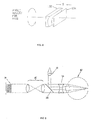
- the light may be injected off axis, so that any reflected light from the cornea is filtered out by the apertures of the system, as shown in Figures 5A and 5B.
- Figure 5B illustrates how the light reflected by the cornea of the eye 40 is blocked by the aperture 36 from entering the wavefront sensor and influencing the measurement. The use of one or more of these schemes is sufficient to allow pre-compensation of the injected beam in accordance with the present invention without introducing unwanted reflections.
- a second telescope may be used in conjunction with the first telescope to increase the dynamic range by providing an alternative location for the filtering aperture.
- one telescope can be completely fixed, while the other has a degree of freedom allowing movement until the lenses of the two telescopes are in contact.
- Figure 6 Such a configuration is shown in Figure 6 , in which a fixed telescope 51 with lenses 52, 54 and aperture 56, is used to supply light to the wavefront sensor 50. This is in conjunction with the elements discussed above regarding Figure 1 . For simplicity, only the essential elements of the light delivery system 14, the collimating lens 16, the polarizing beam splitter 22, the adjustable telescope 30, and the eye 40, have been shown.
- the telescope 30 may be a cylindrical lens telescope or a pair of positive and negative lenses. Such a cylindrical lens configuration is shown in Figure 8 , in which a pair of cylindrical lenses 132, 134 is used in place of lenses 32, 34. The spacing s between the lenses may be adjusted to increase or decrease power of the telescope. The angle of the pair 120, 122 is adjusted relative to the axis of the transmission path. This complicates the instrument, but provides for a better beam projected into the eye, requiring a wavefront sensor of only limited dynamic range, since both spherical and cylindrical aberrations would be subtracted from the wavefront, and only higher order terms would remain.
- a high dynamic range wavefront sensor can be used. Since, in accordance with the present invention, only a small beam is injected into the eye, which will only pick up only a small wavefront aberration across its aperture, the focal spot on the eye will still be quite small, even with some astigmatism. Thus, cylindrical compensation is usually not needed. While some distortion will take place, it will be limited in size and an adequately small spot will still be realized.
- a high dynamic range wavefront sensor corresponds to the use of a smaller focal length for the wavefront sensor lenslet array, as set forth in Equations (3) and (7). While the use of only spherical lenses will result in a loss of accuracy, the larger number of measurements afforded by the smaller lenslet array will sufficiently compensate for this degradation.
- An alternative to using the telescope with a movable lens, as shown in Figure 1 , for correcting base aberrations of the eye in the injected and reflected wavefront includes placing a corrective lens in front of the eye. If this lens is not a contact lens, it cannot be placed at the actual pupil plane of the eye, as shown in Figure 9 , in which a corrective lens 35 is placed adjacent to the eye 40. Thus, there will always be some magnification introduced by the combination of the refractive error of the eye and the correcting lens. Since it is difficult to set or know the vertex distance of the corrective lens, this magnification would be poorly known at best, and introduce error into the entire measurement.
- a lens 37 in Figure 7 may be from a trial lens kit, such as is commonly used for measuring a patient's manifest refraction, but is limited to the prescription accuracy.
- the lens 37 in Figure 7 may be a variable focal length lens, e.g., adaptive optics, liquid crystal displays, deformable mirrors.
- the focal lengths of these elements may be controlled electronically, e.g., by the processor 68 shown in Figure 1 , rather than by movement.
- Either of these configurations is shown in Figure 7 , in which the lens 37 may be a trial lens or a variable focal length lens.
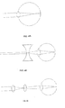
- the applicability of these configurations and the telescope configuration is shown in Figure 4A-4C , in which the size of the spot in a myopic eye alone is shown in Figure 4A , the size of the spot size with correction with a lens 37 is shown in Figure 4B and the spot size with the adjustable telescope 30 is shown in Figure 4C .
- both configurations in Figures 4B and 4C result in the desired small spot size of the present invention.
- a small focal spot can be created on the retina.
- This small focal spot will concentrate light more, allowing the light to be divided into a larger number of focal spots.
- Higher spatial resolution means that the assumption that each lenslet measures only tilt is valid over a much larger range.
- Higher spatial resolution also leads to greater dynamic range and accuracy.
- Higher dynamic range means that measurement of even high order terms of aberration can be accomplished accurately, without significant degradation of the measurement.
Landscapes
- Health & Medical Sciences (AREA)
- Life Sciences & Earth Sciences (AREA)
- Ophthalmology & Optometry (AREA)
- Physics & Mathematics (AREA)
- General Health & Medical Sciences (AREA)
- Public Health (AREA)
- Molecular Biology (AREA)
- Biophysics (AREA)
- Engineering & Computer Science (AREA)
- Biomedical Technology (AREA)
- Heart & Thoracic Surgery (AREA)
- Medical Informatics (AREA)
- Veterinary Medicine (AREA)
- Surgery (AREA)
- Animal Behavior & Ethology (AREA)
- General Physics & Mathematics (AREA)
- Optics & Photonics (AREA)
- Eye Examination Apparatus (AREA)
- Testing Of Optical Devices Or Fibers (AREA)
- Prostheses (AREA)
Applications Claiming Priority (3)
| Application Number | Priority Date | Filing Date | Title |
|---|---|---|---|
| US18208800P | 2000-02-11 | 2000-02-11 | |
| US09/692,483 US6550917B1 (en) | 2000-02-11 | 2000-10-20 | Dynamic range extension techniques for a wavefront sensor including use in ophthalmic measurement |
| EP01925086.9A EP1255483B1 (fr) | 2000-02-11 | 2001-02-08 | Techniques d'extension de plage dynamique, destinees a un capteur de front d'onde, utile notamment dans une mesure ophtalmique |
Related Parent Applications (2)
| Application Number | Title | Priority Date | Filing Date |
|---|---|---|---|
| EP01925086.9A Division EP1255483B1 (fr) | 2000-02-11 | 2001-02-08 | Techniques d'extension de plage dynamique, destinees a un capteur de front d'onde, utile notamment dans une mesure ophtalmique |
| EP01925086.9A Division-Into EP1255483B1 (fr) | 2000-02-11 | 2001-02-08 | Techniques d'extension de plage dynamique, destinees a un capteur de front d'onde, utile notamment dans une mesure ophtalmique |
Publications (1)
| Publication Number | Publication Date |
|---|---|
| EP2952954A1 true EP2952954A1 (fr) | 2015-12-09 |
Family
ID=26877770
Family Applications (2)
| Application Number | Title | Priority Date | Filing Date |
|---|---|---|---|
| EP01925086.9A Expired - Lifetime EP1255483B1 (fr) | 2000-02-11 | 2001-02-08 | Techniques d'extension de plage dynamique, destinees a un capteur de front d'onde, utile notamment dans une mesure ophtalmique |
| EP15175012.2A Withdrawn EP2952954A1 (fr) | 2000-02-11 | 2001-02-08 | Techniques d'extension de gamme dynamique pour un capteur de front d'onde comprenant une utilisation dans une mesure ophtalmique |
Family Applications Before (1)
| Application Number | Title | Priority Date | Filing Date |
|---|---|---|---|
| EP01925086.9A Expired - Lifetime EP1255483B1 (fr) | 2000-02-11 | 2001-02-08 | Techniques d'extension de plage dynamique, destinees a un capteur de front d'onde, utile notamment dans une mesure ophtalmique |
Country Status (6)
| Country | Link |
|---|---|
| US (2) | US6550917B1 (fr) |
| EP (2) | EP1255483B1 (fr) |
| JP (1) | JP5191622B2 (fr) |
| KR (2) | KR100883739B1 (fr) |
| AU (1) | AU5168101A (fr) |
| WO (1) | WO2001058339A2 (fr) |
Cited By (1)
| Publication number | Priority date | Publication date | Assignee | Title |
|---|---|---|---|---|
| CN110702032A (zh) * | 2019-11-20 | 2020-01-17 | 中国科学院长春光学精密机械与物理研究所 | 一种望远镜主镜检测与标定的对准系统及对准方法 |
Families Citing this family (158)
| Publication number | Priority date | Publication date | Assignee | Title |
|---|---|---|---|---|
| US6619799B1 (en) * | 1999-07-02 | 2003-09-16 | E-Vision, Llc | Optical lens system with electro-active lens having alterably different focal lengths |
| DE19950792A1 (de) * | 1999-10-21 | 2001-04-26 | Technolas Gmbh | Wellenfrontsensor mit Mehrleistungsstrahlmodi und unabhängiger Abgleichkamera |
| CA2388014C (fr) * | 1999-10-21 | 2013-04-16 | Technolas Gmbh Ophthalmologische Systeme | Correction par etapes successives des defauts de refraction ophtalmiques au moyen d'un laser |
| US7455407B2 (en) * | 2000-02-11 | 2008-11-25 | Amo Wavefront Sciences, Llc | System and method of measuring and mapping three dimensional structures |
| US6565209B2 (en) * | 2000-04-25 | 2003-05-20 | Alcon Universal Ltd. | Range-extending system and spatial filter for enhancing Hartmann-Shack images and associated methods |
| DE60228940D1 (de) * | 2001-03-15 | 2008-10-30 | Amo Wavefront Sciences Llc | Hren zur abbildung eines optischen systems |
| US6595643B2 (en) | 2001-06-05 | 2003-07-22 | Adaptive Optics Associates,.Inc. | Ophthalmic imaging instrument that measures and compensates for phase aberrations in reflections derived from light produced by an imaging light source |
| KR20040030844A (ko) * | 2001-07-23 | 2004-04-09 | 비쥬얼 패스웨이즈, 인크. | 백내장 검사 및 정량화 기기 및 방법 |
| JP4157839B2 (ja) * | 2001-08-30 | 2008-10-01 | ユニバーシティー オブ ロチェスター | 生体眼の網膜領域撮像方法及びそのシステム |
| US6631991B2 (en) | 2001-08-31 | 2003-10-14 | Adaptive Optics Associates, Inc. | Ophthalmic instrument having hartmann wavefront sensor deriving location of spots with spot fitting techniques |
| US6827442B2 (en) * | 2001-09-12 | 2004-12-07 | Denwood F. Ross | Ophthalmic wavefront measuring devices |
| US6575572B2 (en) * | 2001-09-21 | 2003-06-10 | Carl Zeiss Ophthalmic Systems, Inc. | Method and apparatus for measuring optical aberrations of an eye |
| DE10154194A1 (de) * | 2001-11-07 | 2003-05-22 | Asclepion Meditec Ag | Verfahren und Vorrichtung zur Messung des Dynamischen Verhaltens eines optischen Systems |
| US7034949B2 (en) | 2001-12-10 | 2006-04-25 | Ophthonix, Inc. | Systems and methods for wavefront measurement |
| US6637884B2 (en) * | 2001-12-14 | 2003-10-28 | Bausch & Lomb Incorporated | Aberrometer calibration |
| DE10202509A1 (de) * | 2002-01-23 | 2003-07-31 | Leica Microsystems | Ophthalmo-Operationsmikroskop |
| US20050174535A1 (en) * | 2003-02-13 | 2005-08-11 | Lai Shui T. | Apparatus and method for determining subjective responses using objective characterization of vision based on wavefront sensing |
| US6761454B2 (en) * | 2002-02-13 | 2004-07-13 | Ophthonix, Inc. | Apparatus and method for determining objective refraction using wavefront sensing |
| FR2837373A1 (fr) * | 2002-03-20 | 2003-09-26 | Luneau Sa | Dispositif de mesure des proprietes optiques de l'oeil |
| EP1511978A4 (fr) * | 2002-05-31 | 2008-03-05 | Wavefront Sciences Inc | Procede et systeme de detection et d'analyse du front d'onde d'un systeme de transmission optique |
| US7494220B2 (en) * | 2002-06-27 | 2009-02-24 | Advanced Medical Optics, Inc. | Method and system for improving accuracy in autorefraction measurements by including measurement distance between the photorecptors and the scattering location in an eye |
| WO2004030588A2 (fr) * | 2002-10-03 | 2004-04-15 | Light Sciences Corporation | Systeme et procede d'excitation d'elements photosensibles des tissus de l'oeil |
| US7195354B2 (en) | 2002-10-04 | 2007-03-27 | The Regents Of The University Of California | Adaptive ophthalmologic system |
| DE10258142A1 (de) * | 2002-12-04 | 2004-06-24 | Carl Zeiss Smt Ag | Vorrichtung zur optischen Vermessung eines Abbildungssystems |
| US8911086B2 (en) | 2002-12-06 | 2014-12-16 | Amo Manufacturing Usa, Llc | Compound modulation transfer function for laser surgery and other optical applications |
| US7276025B2 (en) | 2003-03-20 | 2007-10-02 | Welch Allyn, Inc. | Electrical adapter for medical diagnostic instruments using LEDs as illumination sources |
| US6988801B2 (en) * | 2003-03-25 | 2006-01-24 | University Of Rochester | Compact portable wavefront sensor |
| US7341348B2 (en) * | 2003-03-25 | 2008-03-11 | Bausch & Lomb Incorporated | Moiré aberrometer |
| US7556378B1 (en) | 2003-04-10 | 2009-07-07 | Tsontcho Ianchulev | Intraoperative estimation of intraocular lens power |
| WO2004112576A2 (fr) * | 2003-06-20 | 2004-12-29 | Visx, Incorporated | Systemes et procedes permettant de predire l'acuite visuelle objective sur la base de mesures de surfaces d'ondes |
| US8596787B2 (en) | 2003-06-20 | 2013-12-03 | Amo Manufacturing Usa, Llc | Systems and methods for prediction of objective visual acuity based on wavefront measurements |
| US20050122473A1 (en) * | 2003-11-24 | 2005-06-09 | Curatu Eugene O. | Method and apparatus for aberroscope calibration and discrete compensation |
| WO2005057252A2 (fr) * | 2003-12-02 | 2005-06-23 | Wavetec Vision Systems, Inc. | Refracteur interactif incorporant un capteur de front d'onde et une optique adaptative |
| US7343099B2 (en) | 2004-02-12 | 2008-03-11 | Metrologic Instruments, Inc. | Free space optical (FSO) laser communication system employing fade mitigation measures based on laser beam speckle tracking and locking principles |
| US7296893B2 (en) * | 2004-03-03 | 2007-11-20 | Visx, Incorporated | Transformation methods of wavefront maps from one vertex distance to another |
| US7547102B2 (en) * | 2004-03-03 | 2009-06-16 | Amo Manufacturing Usa, Llc | Wavefront propagation from one plane to another |
| RU2268637C2 (ru) * | 2004-03-22 | 2006-01-27 | Андрей Викторович Ларичев | Аберрометр с системой тестирования остроты зрения (варианты), устройство и способ его настройки |
| ES2665536T3 (es) * | 2004-04-20 | 2018-04-26 | Alcon Research, Ltd. | Microscopio quirúrgico y sensor de frente de onda integrados |
| DE102004037558A1 (de) * | 2004-08-03 | 2006-02-23 | Iroc Ag | System zur Wellenfrontmessung |
| US20060126018A1 (en) * | 2004-12-10 | 2006-06-15 | Junzhong Liang | Methods and apparatus for wavefront sensing of human eyes |
| US20060279699A1 (en) * | 2005-06-14 | 2006-12-14 | Advanced Vision Engineering, Inc | Wavefront fusion algorithms for refractive vision correction and vision diagnosis |
| DE102005031496B4 (de) * | 2005-07-06 | 2007-07-05 | Carl Zeiss Surgical Gmbh | Vorrichtung zum Bestimmen der Wellenfront von Licht- und Operationsmikroskop mit Vorrichtung zum Bestimmen der Wellenfront von Licht |
| DE102005042436C5 (de) * | 2005-09-07 | 2010-05-27 | Carl Zeiss Surgical Gmbh | Ophthalmo-Operationsmikroskop mit Messeinrichtung |
| DE102005046141A1 (de) * | 2005-09-27 | 2007-04-05 | Iroc Ag | Gerät für binokulare Visusprüfung |
| DE102005053297A1 (de) * | 2005-11-08 | 2007-05-10 | Bausch & Lomb Inc. | System und Verfahren zur Korrektur von ophthalmischen Brechungsfehlern |
| US8158917B2 (en) * | 2005-12-13 | 2012-04-17 | Agency For Science Technology And Research | Optical wavefront sensor and optical wavefront sensing method |
| JP2007252402A (ja) | 2006-03-20 | 2007-10-04 | Topcon Corp | 眼科測定装置 |
| US7583389B2 (en) * | 2006-04-07 | 2009-09-01 | Amo Wavefront Sciences, Llc | Geometric measurement system and method of measuring a geometric characteristic of an object |
| US7639369B2 (en) * | 2006-04-13 | 2009-12-29 | Mette Owner-Petersen | Multi-object wavefront sensor with spatial filtering |
| JP4783219B2 (ja) * | 2006-06-16 | 2011-09-28 | 株式会社トプコン | 眼科撮影装置 |
| JP4776450B2 (ja) * | 2006-06-16 | 2011-09-21 | 株式会社トプコン | 眼科撮影装置 |
| DE102006036085A1 (de) * | 2006-08-02 | 2008-02-07 | Bausch & Lomb Incorporated | Verfahren und Vorrichtung zur Berechnung einer Laserschußdatei zur Verwendung in einem Excimer-Laser |
| DE102006036086A1 (de) * | 2006-08-02 | 2008-02-07 | Bausch & Lomb Incorporated | Verfahren und Vorrichtung zur Berechnung einer Laserschußdatei zur Verwendung in einem refraktiven Excimer-Laser |
| US20080084541A1 (en) * | 2006-10-06 | 2008-04-10 | Ming Lai | Ophthalmic system and method |
| US7728961B2 (en) * | 2006-10-31 | 2010-06-01 | Mitutoyo Coporation | Surface height and focus sensor |
| US7575322B2 (en) * | 2007-05-11 | 2009-08-18 | Amo Development Llc. | Auto-alignment and auto-focus system and method |
| US8016420B2 (en) | 2007-05-17 | 2011-09-13 | Amo Development Llc. | System and method for illumination and fixation with ophthalmic diagnostic instruments |
| DE102007023270A1 (de) * | 2007-05-18 | 2008-11-20 | Linos Photonics Gmbh & Co. Kg | Funduskamera |
| US7976163B2 (en) | 2007-06-27 | 2011-07-12 | Amo Wavefront Sciences Llc | System and method for measuring corneal topography |
| US7988290B2 (en) * | 2007-06-27 | 2011-08-02 | AMO Wavefront Sciences LLC. | Systems and methods for measuring the shape and location of an object |
| US9192296B2 (en) | 2007-08-21 | 2015-11-24 | Visionix Ltd. | Multifunctional ophthalmic measurement system |
| US8333474B2 (en) | 2007-10-19 | 2012-12-18 | Wavetec Vision Systems, Inc. | Optical instrument alignment system |
| US7594729B2 (en) | 2007-10-31 | 2009-09-29 | Wf Systems, Llc | Wavefront sensor |
| US7723657B2 (en) * | 2007-11-16 | 2010-05-25 | Mitutoyo Corporation | Focus detection apparatus having extended detection range |
| US7802883B2 (en) | 2007-12-20 | 2010-09-28 | Johnson & Johnson Vision Care, Inc. | Cosmetic contact lenses having a sparkle effect |
| EP2232198B1 (fr) | 2008-01-08 | 2015-06-24 | AMO WaveFront Sciences, LLC | Systèmes et procédés pour mesurer une forme de surface |
| EP2103249B9 (fr) | 2008-03-19 | 2016-10-19 | Carl Zeiss Meditec AG | Système de microscopie chirurgicale disposant d'une installation de tomographie à cohérence optique |
| DE102008028509A1 (de) * | 2008-06-16 | 2009-12-24 | Technolas Gmbh Ophthalmologische Systeme | Behandlungsmusterüberwachungsvorrichtung |
| EP2306889A4 (fr) * | 2008-07-10 | 2012-11-28 | Univ Indiana Res & Tech Corp | Appareils ophtalmiques, systèmes et procédés |
| DE102008035995A1 (de) * | 2008-08-01 | 2010-02-04 | Technolas Perfect Vision Gmbh | Kombination einer Excimer-Laserablation und Femtosekundenlasertechnik |
| CN102137617A (zh) * | 2008-08-28 | 2011-07-27 | 泰克诺拉斯完美视觉股份有限公司 | 眼睛测量和建模技术 |
| US8459795B2 (en) | 2008-09-16 | 2013-06-11 | Carl Zeiss Meditec Ag | Measuring system for ophthalmic surgery |
| DE102008047400B9 (de) | 2008-09-16 | 2011-01-05 | Carl Zeiss Surgical Gmbh | Augenchirurgie-Messsystem |
| JP5335922B2 (ja) | 2008-09-29 | 2013-11-06 | サイファイ メドテック エッセ.エッレ.エッレ. | カスタマイズされたバイオメトリック眼内レンズを設計および移植するためのシステムおよび方法 |
| DE102008053827A1 (de) | 2008-10-30 | 2010-05-12 | Technolas Perfect Vision Gmbh | Vorrichtung und Verfahren zum Bereitstellen einer Laserschussdatei |
| US8254724B2 (en) | 2008-11-06 | 2012-08-28 | Bausch & Lomb Incorporated | Method and apparatus for making and processing aberration measurements |
| US8550624B2 (en) | 2008-11-06 | 2013-10-08 | Wavetec Vision Systems, Inc. | Optical angular measurement system for ophthalmic applications and method for positioning of a toric intraocular lens with increased accuracy |
| US7980698B2 (en) | 2008-11-19 | 2011-07-19 | Bausch & Lomb Incorporated | Power-adjusted aberrometer |
| KR200453632Y1 (ko) * | 2009-02-24 | 2011-05-16 | 김형도 | 건식습식 겸용 히팅장치 |
| WO2013013175A1 (fr) | 2011-07-20 | 2013-01-24 | Amo Development, Llc. | Systèmes et procédés de traitement de réfraction manifeste |
| US8876290B2 (en) | 2009-07-06 | 2014-11-04 | Wavetec Vision Systems, Inc. | Objective quality metric for ocular wavefront measurements |
| EP2818130B1 (fr) * | 2009-07-14 | 2017-09-27 | WaveTec Vision Systems, Inc. | Détermination de la position de lentille efficace d'une lentille intraoculaire à l'aide d'une puissance de réfraction aphaque |
| CN102497833B (zh) | 2009-07-14 | 2014-12-03 | 波技术视觉系统公司 | 眼科手术测量系统 |
| CN102667439B (zh) | 2009-10-20 | 2015-11-25 | 株式会社尼康 | 用于测量波前像差的方法和波前像差测量设备 |
| JP5574670B2 (ja) * | 2009-10-30 | 2014-08-20 | キヤノン株式会社 | 補償光学装置、撮像装置および補償光学方法 |
| US9504376B2 (en) | 2009-12-22 | 2016-11-29 | Amo Wavefront Sciences, Llc | Optical diagnosis using measurement sequence |
| US8786210B2 (en) | 2010-06-30 | 2014-07-22 | Welch Allyn, Inc. | Drive circuit for light emitting diode |
| US8459844B2 (en) | 2010-07-01 | 2013-06-11 | Welch Allyn, Inc. | Replacement light assembly |
| US10132925B2 (en) | 2010-09-15 | 2018-11-20 | Ascentia Imaging, Inc. | Imaging, fabrication and measurement systems and methods |
| WO2012037343A1 (fr) * | 2010-09-15 | 2012-03-22 | Ascentia Imaging, Inc. | Systèmes et procédés d'imagerie, de fabrication et de mesure |
| US10582847B2 (en) | 2010-12-30 | 2020-03-10 | Amo Wavefront Sciences, Llc | Method and system for eye measurements and cataract surgery planning using vector function derived from prior surgeries |
| EP3213724B1 (fr) | 2010-12-30 | 2019-09-18 | Amo Wavefront Sciences, LLC | Procédé de planification de traitement amélioré et système de commande de chirurgie réfractive au laser |
| US10582846B2 (en) | 2010-12-30 | 2020-03-10 | Amo Wavefront Sciences, Llc | Method and system for eye measurements and cataract surgery planning using vector function derived from prior surgeries |
| US10583039B2 (en) | 2010-12-30 | 2020-03-10 | Amo Wavefront Sciences, Llc | Method and system for eye measurements and cataract surgery planning using vector function derived from prior surgeries |
| FR2971693B1 (fr) * | 2011-02-22 | 2013-03-08 | Imagine Eyes | Methode et dispositif d'imagerie retinienne a haute resolution |
| US20140088573A1 (en) * | 2011-03-04 | 2014-03-27 | Eyesight & Vision Gmbh | Projector device, and medical device comprising the projector device |
| US8622546B2 (en) | 2011-06-08 | 2014-01-07 | Amo Wavefront Sciences, Llc | Method of locating valid light spots for optical measurement and optical measurement instrument employing method of locating valid light spots |
| US9739864B2 (en) | 2012-01-03 | 2017-08-22 | Ascentia Imaging, Inc. | Optical guidance systems and methods using mutually distinct signal-modifying |
| CN104246826B (zh) | 2012-01-03 | 2017-12-15 | 阿森蒂亚影像有限公司 | 编码定位系统、方法和装置 |
| EP2656781A1 (fr) * | 2012-04-24 | 2013-10-30 | Popovic, Zoran | Génération d'étoiles de guidage |
| US9072462B2 (en) | 2012-09-27 | 2015-07-07 | Wavetec Vision Systems, Inc. | Geometric optical power measurement device |
| EP2727516B1 (fr) * | 2012-10-30 | 2020-01-01 | Canon Kabushiki Kaisha | Appareil ophtalmologique |
| US9625723B2 (en) * | 2013-06-25 | 2017-04-18 | Microsoft Technology Licensing, Llc | Eye-tracking system using a freeform prism |
| US10228561B2 (en) * | 2013-06-25 | 2019-03-12 | Microsoft Technology Licensing, Llc | Eye-tracking system using a freeform prism and gaze-detection light |
| JP2015072136A (ja) * | 2013-10-01 | 2015-04-16 | 株式会社 光コム | 光学式計測装置 |
| JP2015072137A (ja) * | 2013-10-01 | 2015-04-16 | 株式会社 光コム | 光学式計測装置 |
| ITFI20130229A1 (it) * | 2013-10-02 | 2015-04-03 | Strumenti Oftalmici C S O S R L Costruzioni | Apparato e metodo per la misura di aberrazioni del sistema ottico di un essere vivente |
| CA2916561A1 (fr) | 2013-11-26 | 2015-06-04 | Abbott Medical Optics Inc. | Systeme et procede pour mesurer une dysphotopsie |
| US10952606B2 (en) | 2014-07-02 | 2021-03-23 | Amo Development, Llc | Optical measurement system and method including blink rate monitor and/or tear film breakup detector |
| CA2953402A1 (fr) | 2014-07-02 | 2016-01-07 | Amo Wavefront Sciences, Llc | Systeme et procede de mesure optique comprenant un moniteur de frequence de clignement des yeux et/ou un detecteur de rupture de film lacrymal |
| US9757025B2 (en) | 2014-07-03 | 2017-09-12 | Amo Wavefront Sciences, Llc | Optical measurement system and method with target brightness level adjustment |
| CN104236856B (zh) * | 2014-09-10 | 2017-01-18 | 中国科学院上海光学精密机械研究所 | 物镜成像系统的波像差检测装置及其系统误差校正方法 |
| JP6696977B2 (ja) | 2014-09-19 | 2020-05-20 | カール・ツアイス・メディテック・アーゲー | ズーム可能なケプラーシステムを備える光学コヒーレンストモグラフィのシステム |
| AU2015381755A1 (en) | 2015-02-06 | 2017-08-24 | Amo Wavefront Sciences, Llc. | Systems and methods of optical coherence tomography with a multi-focal delay line |
| CA2977329C (fr) | 2015-02-20 | 2018-06-19 | REBIScan, Inc. | Procede et appareil de mesure de fixation et de mesure d'erreur de refraction utilisant l'erreur de front d'onde |
| US10126114B2 (en) | 2015-05-21 | 2018-11-13 | Ascentia Imaging, Inc. | Angular localization system, associated repositionable mechanical structure, and associated method |
| DE102015008922B4 (de) | 2015-07-10 | 2019-03-07 | Carl Zeiss Meditec Ag | Vorrichtung zur Bestimmung einer Ametropie eines Auges |
| CA2991484A1 (fr) | 2015-07-27 | 2017-02-02 | Amo Wavefront Sciences Llc | Systemes d'imagerie et de mesure optique et procedes pour la chirurgie de la cataracte et la planification de traitement |
| CN104993357B (zh) * | 2015-08-11 | 2018-09-18 | 京东方科技集团股份有限公司 | 不可见激光器系统及其光路可视化方法 |
| WO2017059291A1 (fr) | 2015-10-01 | 2017-04-06 | Amo Wavefront Sciences, Llc | Systèmes et procédés de mesure optique avec ajustements d'aberration chromatique personnalisés |
| CA3005955A1 (fr) | 2015-11-23 | 2017-06-01 | Amo Wavefront Sciences, Llc | Procede et systeme de mesures oculaires et planification d'une chirurgie de la cataracte en utilisant la fonction vectorielle derivee de chirurgies anterieures |
| CA3020442A1 (fr) | 2016-04-13 | 2017-10-19 | Amo Wavefront Sciences, Llc | Appareil, systeme et procede pour calcul de puissance de lentille intraoculaire utilisant une formule de regression incorporant une aberration spherique corneenne |
| EP3782591B1 (fr) | 2016-07-07 | 2023-11-29 | AMO Development, LLC | Incision laser lenticulaire utilisant des cartes guidées de front d'onde |
| CN115363519B (zh) | 2016-08-31 | 2026-04-21 | 株式会社尼康 | 基于手机的眼底相机的广角光瞳中继器 |
| AU2017324944B2 (en) * | 2016-09-06 | 2022-04-07 | Amo Development, Llc | Optical measurement systems and processes with wavefront aberrometer having variable focal length lens |
| US11013594B2 (en) | 2016-10-25 | 2021-05-25 | Amo Groningen B.V. | Realistic eye models to design and evaluate intraocular lenses for a large field of view |
| DE102017105580B4 (de) * | 2016-11-04 | 2025-10-02 | Carl Zeiss Meditec Ag | Operationsmikroskop |
| WO2018089682A1 (fr) | 2016-11-09 | 2018-05-17 | Amo Wavefront Sciences, Llc | Systèmes et procédés de tomographie par cohérence optique avec compensation de dispersion |
| WO2018160711A1 (fr) | 2017-02-28 | 2018-09-07 | Amo Wavefront Sciences, Llc | Procédé et système de rétro-éclairage de pupille utilisant un bras d'échantillon d'interféromètre de tomographie par cohérence optique |
| US10739227B2 (en) | 2017-03-23 | 2020-08-11 | Johnson & Johnson Surgical Vision, Inc. | Methods and systems for measuring image quality |
| DE102017117925A1 (de) | 2017-08-07 | 2019-02-07 | Carl Zeiss Meditec Ag | Konfokales Refraktometer zur Bestimmung der Refraktion eines Auges eines Patienten |
| CA3082053A1 (fr) | 2017-11-30 | 2019-06-06 | Amo Groningen B.V. | Lentilles intraoculaires permettant d'ameliorer l'independance vis a vis des lunettes apres une intervention chirurgicale et leurs procedes de fabrication |
| US11026575B2 (en) | 2018-01-23 | 2021-06-08 | Amo Development, Llc | Methods and systems of optical coherence tomography with fiducial signal for correcting scanning laser nonlinearity |
| EP3773145A1 (fr) | 2018-04-06 | 2021-02-17 | AMO Development LLC | Procédés et systèmes pour une topographie cornéenne au moyen d'une imagerie sclérale à focalisation |
| US10942369B2 (en) * | 2018-07-17 | 2021-03-09 | International Business Machines Corporation | Smart contact lens control system |
| DE102018118352A1 (de) | 2018-07-30 | 2020-01-30 | Carl Zeiss Meditec Ag | Ophthalmologisches Operationsmikroskop |
| US11246484B2 (en) | 2018-08-20 | 2022-02-15 | Amo Development, Llc | Methods and systems for eye measurement with in-focus iris and scleral imaging |
| US12383124B2 (en) * | 2018-10-25 | 2025-08-12 | Beyeonics Surgical Ltd | Systems and methods for imaging a body part during a medical procedure |
| US11006823B2 (en) | 2019-01-28 | 2021-05-18 | Amo Development, Llc | Methods and systems for optical coherence tomography scanning of cornea and retina |
| CA3101526A1 (fr) | 2019-05-23 | 2020-11-26 | Amo Development, Llc | Procede et systeme de realisation d'une mesure optique de l'il |
| EP4076134A1 (fr) * | 2019-12-20 | 2022-10-26 | AMO Development, LLC | Systèmes et procédés de mesure optique avec une projection non télécentrique de la cible de fixation à l'oeil |
| GB201918993D0 (en) * | 2019-12-20 | 2020-02-05 | Univ Dublin Technological | A system and method of determining the ocular biometric status of a patient |
| EP4081093A1 (fr) | 2019-12-23 | 2022-11-02 | AMO Development, LLC | Systèmes et procédés de mesure optique avec cible de fixation à compensation cylindrique |
| WO2021137032A1 (fr) * | 2019-12-30 | 2021-07-08 | Amo Development, Llc | Systèmes et procédés de mesure optique avec cible de fixation ayant une compensation de bokeh |
| IL294563B1 (en) * | 2020-01-14 | 2026-04-01 | Pxe Computational Imaging Ltd | System and method for optical imaging and measurement of objects |
| US12285214B2 (en) | 2020-02-21 | 2025-04-29 | Wavefront Dynamics Inc. | Wide-field multi-axis aberrometer |
| US12245972B2 (en) | 2020-02-21 | 2025-03-11 | Wavefront Dynamics, Inc. | System and methods for customizing an intraocular lens using a wavefront aberrometer |
| TW202211862A (zh) * | 2020-07-16 | 2022-04-01 | 美商愛奎有限公司 | 測量折射的裝置和方法 |
| EP4228573A1 (fr) * | 2020-10-16 | 2023-08-23 | AMO Development, LLC | Mesure de taille de point focal laser en utilisant une caméra intégrée pour un système laser ophtalmique |
| CN112790895B (zh) * | 2020-12-28 | 2022-12-27 | 上海美沃精密仪器股份有限公司 | 一种人工晶体补偿校正系统及方法 |
| US11963722B2 (en) | 2021-04-13 | 2024-04-23 | Amo Development, Llc | Methods and systems for determining change in eye position between successive eye measurements |
| US12245811B2 (en) | 2021-04-15 | 2025-03-11 | Amo Development, Llc | Methods and systems for thickness measurements using spectrally resolved full gradient topography |
| US12048484B2 (en) | 2021-04-21 | 2024-07-30 | Amo Development, Llc | Compact autocylinder compensation module for autorefractor and autorefractor with autocylinder compensation module |
| EP4333685B1 (fr) | 2021-05-05 | 2026-01-14 | AMO Groningen B.V. | Système d'halomètre annulaire et procédé de quantification de dysphotopsies |
| US12343081B2 (en) | 2021-05-19 | 2025-07-01 | Wavefront Dynamics, Inc. | Optical aberrometer systems for customizing intraocular lens |
| US12458536B2 (en) | 2021-05-19 | 2025-11-04 | Wavefront Dynamics, Inc. | Methods for customizing intraocular lens using an optical aberrometer |
| US12496790B2 (en) | 2022-06-03 | 2025-12-16 | Wavefront Dynamnics Inc. | Customized manufacture of molds for making wavefront-customized contact lens using a wavefront aberrometer |
| CN118266857B (zh) * | 2024-05-31 | 2024-08-13 | 瑞尔明康(浙江)医疗科技有限公司 | 人眼测量系统 |
Citations (9)
| Publication number | Priority date | Publication date | Assignee | Title |
|---|---|---|---|---|
| US3819256A (en) * | 1972-08-11 | 1974-06-25 | H Borough | Apparatus for refracting the eye |
| US4021102A (en) * | 1973-11-26 | 1977-05-03 | Kabushiki Kaisha Hoya Lens | Auto-refractometer |
| WO1983002716A1 (fr) * | 1982-02-12 | 1983-08-18 | Helmut Krueger | Appareil et procede de mesure de la refraction |
| EP0373788A2 (fr) * | 1988-12-06 | 1990-06-20 | Kabushiki Kaisha TOPCON | Appareil pour mesurer la vergence oculaire |
| US5258791A (en) * | 1990-07-24 | 1993-11-02 | General Electric Company | Spatially resolved objective autorefractometer |
| DE4222395A1 (de) * | 1992-07-08 | 1994-01-13 | Amtech Ges Fuer Angewandte Mic | Vorrichtung und Verfahren zur Messung der Augenrefraktion |
| EP0625332A2 (fr) * | 1993-04-16 | 1994-11-23 | Canon Kabushiki Kaisha | Visionneuse |
| US5777719A (en) | 1996-12-23 | 1998-07-07 | University Of Rochester | Method and apparatus for improving vision and the resolution of retinal images |
| US5929970A (en) * | 1997-05-13 | 1999-07-27 | Kabushiki Kaisha Topcon | Optical characteristic measuring apparatus |
Family Cites Families (26)
| Publication number | Priority date | Publication date | Assignee | Title |
|---|---|---|---|---|
| US4471447A (en) * | 1981-09-08 | 1984-09-11 | Hughes Aircraft Company | Method for aligning an optical system utilizing focal plane image intensity data |
| JPS59101129A (ja) * | 1982-11-30 | 1984-06-11 | キヤノン株式会社 | 眼科器械の位置合わせ精度判定装置 |
| US4725138A (en) | 1985-05-22 | 1988-02-16 | Adaptive Optics Associates Incorporated | Optical wavefront sensing system |
| US4729652A (en) * | 1985-11-04 | 1988-03-08 | Eye Research Institute Of Retina Foundation | Apparatus and method for determining angular orientation of eye |
| US4960327A (en) * | 1987-07-15 | 1990-10-02 | Kabushiki Kaisha Topcon | Optical system in a lasar scanning eye fundus camera |
| US4996412A (en) * | 1989-12-07 | 1991-02-26 | United Technologies Corporation | Optical system for wavefront compensation |
| US5526072A (en) * | 1993-04-14 | 1996-06-11 | Alcon Laboratories, Inc. | Apparatus and technique for automatic centering and focusing a corneal topographer |
| GB9323065D0 (en) * | 1993-11-09 | 1994-01-05 | Besca Ltd | A wide field retinal scanning ophthalmoscope |
| US5617157A (en) * | 1994-06-15 | 1997-04-01 | Metaphase Ophthalmic Corp. | Computer controlled subjective refractor |
| US5493391A (en) | 1994-07-11 | 1996-02-20 | Sandia Corporation | One dimensional wavefront distortion sensor comprising a lens array system |
| JPH08136852A (ja) * | 1994-11-02 | 1996-05-31 | Olympus Optical Co Ltd | 接眼光学系を有する光学装置 |
| US5978053A (en) | 1995-07-07 | 1999-11-02 | New Mexico State University Technology Transfer Corporation | Characterization of collimation and beam alignment |
| US5936720A (en) | 1996-07-10 | 1999-08-10 | Neal; Daniel R. | Beam characterization by wavefront sensor |
| US6052180A (en) | 1996-07-10 | 2000-04-18 | Wavefront Sciences, Inc. | Apparatus and method for characterizing pulsed light beams |
| US6130419A (en) | 1996-07-10 | 2000-10-10 | Wavefront Sciences, Inc. | Fixed mount wavefront sensor |
| JPH1090117A (ja) * | 1996-09-11 | 1998-04-10 | Ricoh Co Ltd | 屈折率分布の測定方法及び装置 |
| US6271914B1 (en) | 1996-11-25 | 2001-08-07 | Autonomous Technologies Corporation | Objective measurement and correction of optical systems using wavefront analysis |
| JPH11137522A (ja) * | 1997-11-11 | 1999-05-25 | Topcon Corp | 光学特性測定装置 |
| AU740673B2 (en) * | 1997-11-21 | 2001-11-08 | Autonomous Technologies Corporation | Objective measurement and correction of optical systems using wavefront analysis |
| PT1105037E (pt) | 1998-08-19 | 2002-11-29 | Autonomous Technologies Corp | Aparelho e metodo para medir defeitos de visao de um olho humano |
| DE19950792A1 (de) | 1999-10-21 | 2001-04-26 | Technolas Gmbh | Wellenfrontsensor mit Mehrleistungsstrahlmodi und unabhängiger Abgleichkamera |
| US6199986B1 (en) | 1999-10-21 | 2001-03-13 | University Of Rochester | Rapid, automatic measurement of the eye's wave aberration |
| BR0106071A (pt) | 2000-04-19 | 2002-04-02 | Alcon Universal Ltd | Sensor de frente de onda para mensuração objetiva de um sistema ótico e métodos associados |
| CA2377852C (fr) | 2000-04-25 | 2007-08-07 | Alcon Universal Ltd. | Filtre spatial destine a renforcer des images hartmann-shack images, et methodes connexes |
| US6382795B1 (en) | 2000-05-20 | 2002-05-07 | Carl Zeiss, Inc. | Method and apparatus for measuring refractive errors of an eye |
| US6394605B1 (en) | 2001-05-23 | 2002-05-28 | Alcon Universal Ltd. | Fogging method for a wavefront sensor |
-
2000
- 2000-10-20 US US09/692,483 patent/US6550917B1/en not_active Expired - Lifetime
-
2001
- 2001-02-08 KR KR1020027010362A patent/KR100883739B1/ko not_active Expired - Fee Related
- 2001-02-08 AU AU5168101A patent/AU5168101A/xx active Pending
- 2001-02-08 EP EP01925086.9A patent/EP1255483B1/fr not_active Expired - Lifetime
- 2001-02-08 JP JP2001557456A patent/JP5191622B2/ja not_active Expired - Fee Related
- 2001-02-08 KR KR1020087016170A patent/KR20080069716A/ko not_active Withdrawn
- 2001-02-08 WO PCT/US2001/040053 patent/WO2001058339A2/fr not_active Ceased
- 2001-02-08 EP EP15175012.2A patent/EP2952954A1/fr not_active Withdrawn
-
2003
- 2003-04-21 US US10/419,072 patent/US20030193647A1/en not_active Abandoned
Patent Citations (10)
| Publication number | Priority date | Publication date | Assignee | Title |
|---|---|---|---|---|
| US3819256A (en) * | 1972-08-11 | 1974-06-25 | H Borough | Apparatus for refracting the eye |
| US4021102A (en) * | 1973-11-26 | 1977-05-03 | Kabushiki Kaisha Hoya Lens | Auto-refractometer |
| WO1983002716A1 (fr) * | 1982-02-12 | 1983-08-18 | Helmut Krueger | Appareil et procede de mesure de la refraction |
| EP0373788A2 (fr) * | 1988-12-06 | 1990-06-20 | Kabushiki Kaisha TOPCON | Appareil pour mesurer la vergence oculaire |
| US5258791A (en) * | 1990-07-24 | 1993-11-02 | General Electric Company | Spatially resolved objective autorefractometer |
| DE4222395A1 (de) * | 1992-07-08 | 1994-01-13 | Amtech Ges Fuer Angewandte Mic | Vorrichtung und Verfahren zur Messung der Augenrefraktion |
| EP0625332A2 (fr) * | 1993-04-16 | 1994-11-23 | Canon Kabushiki Kaisha | Visionneuse |
| US5777719A (en) | 1996-12-23 | 1998-07-07 | University Of Rochester | Method and apparatus for improving vision and the resolution of retinal images |
| US5949521A (en) | 1996-12-23 | 1999-09-07 | University Of Rochester | Method and apparatus for improving vision and the resolution of retinal images |
| US5929970A (en) * | 1997-05-13 | 1999-07-27 | Kabushiki Kaisha Topcon | Optical characteristic measuring apparatus |
Non-Patent Citations (1)
| Title |
|---|
| J. LIANG ET AL.: "Objective measurement of wave aberrations of the human eye with the use of a Hartmann-Shack wave-front sensor", J. OPT. SOC. AM., vol. 11, no. 7, July 1994 (1994-07-01), US, pages 1949 - 1957, XP000955413 * |
Cited By (1)
| Publication number | Priority date | Publication date | Assignee | Title |
|---|---|---|---|---|
| CN110702032A (zh) * | 2019-11-20 | 2020-01-17 | 中国科学院长春光学精密机械与物理研究所 | 一种望远镜主镜检测与标定的对准系统及对准方法 |
Also Published As
| Publication number | Publication date |
|---|---|
| KR100883739B1 (ko) | 2009-02-12 |
| WO2001058339A2 (fr) | 2001-08-16 |
| JP5191622B2 (ja) | 2013-05-08 |
| WO2001058339A3 (fr) | 2002-07-04 |
| JP2004500195A (ja) | 2004-01-08 |
| KR20080069716A (ko) | 2008-07-28 |
| WO2001058339A9 (fr) | 2003-02-06 |
| EP1255483A2 (fr) | 2002-11-13 |
| AU5168101A (en) | 2001-08-20 |
| EP1255483B1 (fr) | 2015-08-05 |
| US6550917B1 (en) | 2003-04-22 |
| US20030193647A1 (en) | 2003-10-16 |
| KR20020086519A (ko) | 2002-11-18 |
Similar Documents
| Publication | Publication Date | Title |
|---|---|---|
| EP1255483B1 (fr) | Techniques d'extension de plage dynamique, destinees a un capteur de front d'onde, utile notamment dans une mesure ophtalmique | |
| US20100045934A1 (en) | Dynamic range extension techniques for a wavefront sensor including use in ophthalmic measurement | |
| CA2338060C (fr) | Dispositif de mesure des defauts de la vision chez l'homme et methode afferente | |
| US7891812B2 (en) | Aberrometer provided with a visual acuity testing system | |
| US6439720B1 (en) | Method and apparatus for measuring optical aberrations of the human eye | |
| RU2573179C2 (ru) | Последовательный датчик волнового фронта с большим диоптрийным диапазоном, предоставляющий информацию в реальном времени | |
| US7036934B1 (en) | Wavefront sensor having multi-power modes, independent adjustment camera, and accommodation range measurement | |
| JP4249016B2 (ja) | 眼用波面測定装置 | |
| EP1210003B1 (fr) | Appareil et procede de mesure et de correction objectives de systemes optiques par analyse de front d'ondes | |
| US6273566B1 (en) | Ophthalmologic characteristic measuring apparatus | |
| US20040130677A1 (en) | Apparatus and method for measuring vision defects of a human eye | |
| US20140081247A1 (en) | Projector device with self-correcting function, and medical device comprising the projector device | |
| EP1619999B1 (fr) | Capteur a front d'onde portable compact | |
| US5309186A (en) | Eye refractive power measuring apparatus having opacity discriminant function of crystalline lens | |
| MXPA01013364A (es) | Filtro especial para mejorar las imagenes hartmann-shack, y metodos asociados. | |
| US5198867A (en) | Adaption of lensmeter optics for minimizing contact lens spherical aberration | |
| EP1593945A1 (fr) | Capteur de front d'onde et relais pour une mesure optique et méthodes associées. | |
| JP4252288B2 (ja) | 眼特性測定装置 | |
| US7213919B2 (en) | Method and device for calibrating an optical wavefront system | |
| US20020063849A1 (en) | Eye characteristic measuring apparatus | |
| JP2004159779A (ja) | 眼特性測定装置 | |
| US20030156256A1 (en) | Eye's optical characteristic measuring system | |
| WO2020234805A1 (fr) | Procédé et système de réalisation d'une mesure optique de l'œil | |
| HK1076021A (en) | Apparatus and the associated methods for calibrating a wavefront sensor |
Legal Events
| Date | Code | Title | Description |
|---|---|---|---|
| PUAI | Public reference made under article 153(3) epc to a published international application that has entered the european phase |
Free format text: ORIGINAL CODE: 0009012 |
|
| AC | Divisional application: reference to earlier application |
Ref document number: 1255483 Country of ref document: EP Kind code of ref document: P |
|
| AK | Designated contracting states |
Kind code of ref document: A1 Designated state(s): AT BE CH CY DE DK ES FI FR GB GR IE IT LI LU MC NL PT SE TR |
|
| 17P | Request for examination filed |
Effective date: 20160518 |
|
| RBV | Designated contracting states (corrected) |
Designated state(s): AT BE CH CY DE DK ES FI FR GB GR IE IT LI LU MC NL PT SE TR |
|
| 17Q | First examination report despatched |
Effective date: 20190624 |
|
| STAA | Information on the status of an ep patent application or granted ep patent |
Free format text: STATUS: THE APPLICATION IS DEEMED TO BE WITHDRAWN |
|
| 18D | Application deemed to be withdrawn |
Effective date: 20200108 |