EP2952980A1 - Prozesssteuerungsverfahren, -vorrichtung und -system - Google Patents
Prozesssteuerungsverfahren, -vorrichtung und -system Download PDFInfo
- Publication number
- EP2952980A1 EP2952980A1 EP13874187.1A EP13874187A EP2952980A1 EP 2952980 A1 EP2952980 A1 EP 2952980A1 EP 13874187 A EP13874187 A EP 13874187A EP 2952980 A1 EP2952980 A1 EP 2952980A1
- Authority
- EP
- European Patent Office
- Prior art keywords
- control
- quantity correction
- correction value
- collected
- wireless sensor
- Prior art date
- Legal status (The legal status is an assumption and is not a legal conclusion. Google has not performed a legal analysis and makes no representation as to the accuracy of the status listed.)
- Withdrawn
Links
- 238000000034 method Methods 0.000 title claims abstract description 241
- 238000004886 process control Methods 0.000 title claims abstract description 38
- 230000008569 process Effects 0.000 claims abstract description 210
- 230000005540 biological transmission Effects 0.000 claims abstract description 162
- 238000004519 manufacturing process Methods 0.000 claims abstract description 50
- 238000005070 sampling Methods 0.000 claims abstract description 47
- 238000012937 correction Methods 0.000 claims description 125
- 238000013480 data collection Methods 0.000 claims description 48
- 238000004590 computer program Methods 0.000 claims description 4
- 238000010586 diagram Methods 0.000 description 14
- 238000005259 measurement Methods 0.000 description 11
- 238000005265 energy consumption Methods 0.000 description 7
- 238000012545 processing Methods 0.000 description 6
- 230000008901 benefit Effects 0.000 description 4
- 238000004891 communication Methods 0.000 description 4
- 230000006872 improvement Effects 0.000 description 4
- CURLTUGMZLYLDI-UHFFFAOYSA-N Carbon dioxide Chemical compound O=C=O CURLTUGMZLYLDI-UHFFFAOYSA-N 0.000 description 3
- 238000012369 In process control Methods 0.000 description 3
- 238000004458 analytical method Methods 0.000 description 3
- 238000005516 engineering process Methods 0.000 description 3
- 238000010965 in-process control Methods 0.000 description 3
- 238000004364 calculation method Methods 0.000 description 2
- 229910002092 carbon dioxide Inorganic materials 0.000 description 2
- 239000001569 carbon dioxide Substances 0.000 description 2
- 230000006870 function Effects 0.000 description 2
- 239000007788 liquid Substances 0.000 description 2
- 238000012544 monitoring process Methods 0.000 description 2
- 230000007704 transition Effects 0.000 description 2
- 101000934888 Homo sapiens Succinate dehydrogenase cytochrome b560 subunit, mitochondrial Proteins 0.000 description 1
- 102100025393 Succinate dehydrogenase cytochrome b560 subunit, mitochondrial Human genes 0.000 description 1
- 230000001133 acceleration Effects 0.000 description 1
- 230000009286 beneficial effect Effects 0.000 description 1
- 238000004422 calculation algorithm Methods 0.000 description 1
- 230000001413 cellular effect Effects 0.000 description 1
- 230000008859 change Effects 0.000 description 1
- 239000000470 constituent Substances 0.000 description 1
- 238000001514 detection method Methods 0.000 description 1
- 239000000284 extract Substances 0.000 description 1
- 238000009434 installation Methods 0.000 description 1
- 230000010354 integration Effects 0.000 description 1
- 230000003287 optical effect Effects 0.000 description 1
- 230000010355 oscillation Effects 0.000 description 1
- 238000001139 pH measurement Methods 0.000 description 1
- 230000005855 radiation Effects 0.000 description 1
- 238000006467 substitution reaction Methods 0.000 description 1
Images


Classifications
-
- G—PHYSICS
- G05—CONTROLLING; REGULATING
- G05B—CONTROL OR REGULATING SYSTEMS IN GENERAL; FUNCTIONAL ELEMENTS OF SUCH SYSTEMS; MONITORING OR TESTING ARRANGEMENTS FOR SUCH SYSTEMS OR ELEMENTS
- G05B11/00—Automatic controllers
- G05B11/01—Automatic controllers electric
- G05B11/36—Automatic controllers electric with provision for obtaining particular characteristics, e.g. proportional, integral, differential
-
- G—PHYSICS
- G05—CONTROLLING; REGULATING
- G05B—CONTROL OR REGULATING SYSTEMS IN GENERAL; FUNCTIONAL ELEMENTS OF SUCH SYSTEMS; MONITORING OR TESTING ARRANGEMENTS FOR SUCH SYSTEMS OR ELEMENTS
- G05B2219/00—Program-control systems
- G05B2219/30—Nc systems
- G05B2219/33—Director till display
- G05B2219/33221—Drives, servo units, sensors, motors, on local network, ethernet, tcp-ip, wireless
-
- G—PHYSICS
- G05—CONTROLLING; REGULATING
- G05B—CONTROL OR REGULATING SYSTEMS IN GENERAL; FUNCTIONAL ELEMENTS OF SUCH SYSTEMS; MONITORING OR TESTING ARRANGEMENTS FOR SUCH SYSTEMS OR ELEMENTS
- G05B2219/00—Program-control systems
- G05B2219/30—Nc systems
- G05B2219/37—Measurements
- G05B2219/37494—Intelligent sensor, data handling incorporated in sensor
Definitions
- the present invention relates to the field of control technology, in particular to a process control method, device and system.
- wireless sensors in process control are obvious in this field. For example, fast installation, savings in terms of wiring costs (up to 40 USD per foot of cable), etc.
- application scenarios such as pharmaceutical processing, petrochemical processing, algaculture processing and indoor temperature control are all exemplary applications of wireless sensors in process control.
- Wireless sensors are generally powered by a battery with a limited service life. Depending on the sensor operating conditions, the battery life is usually a few months or several years. The process of communication between a wireless sensor and a process control system consumes most of the power. Thus, by adopting a longer communication interval, the battery service life can be maximized, and the amount of sensor overhaul and servicing work can be reduced.
- a Siemens wireless temperature transmitter SITRANS TF280 wireless HART
- the transmission rate can be adjusted between 8 seconds and 255 seconds, with the factory setting being 60 seconds.
- a longer transmission interval means that the control loop is not optimized, and is likely to oscillate.
- a properly adjusted PI controller may need to be re-adjusted.
- Fig. 1 is a schematic diagram comparing the control performances of two wireless transmission intervals according to the prior art. Refer to Fig. 1 ; in Fig. 1 the control performances of two wireless transmission intervals are compared. For a set value change at 100 seconds, the control parameter (process variable) output of the same PI controller is shown by the dotted line. If the transmission interval is 2 seconds, the process shows good control performance (curve 1). If the user tries increasing the transmission interval to 20 seconds in order to improve the battery service life (curve 2), the control performance suffers as large overswings occur and the transition time increases.
- Most wireless sensor workflows comprise: giving a measurement value, sending the measurement value to a control system, entering a sleep mode to save energy.
- multiple measurement values can be acquired between wireless sensor data transmission processes in order to improve process control robustness, but such data cannot be utilized effectively to improve control performance. For example, even though the average value of a process variable will be sent to the control system in the prior art, the values of multiple measurements between wireless sensor transmission processes are not utilized effectively.
- the embodiments of the present invention propose a process control system, to improve control peformance.
- the embodiments of the present invention propose a process control method, to improve control peformance.
- the embodiments of the present invention propose a wireless sensor, to improve control peformance.
- the embodiments of the present invention propose a controller, to improve control peformance.
- the wireless sensor is used for sending a process parameter collected at a transmission moment and the calculated control quantity correction value to the controller according to the transmission frequency, or sending an average value of process parameters collected in a data transmission period and the calculated control quantity correction value to the controller according to the transmission frequency.
- the wireless sensor is used for subtracting a process parameter sent in the previous data transmission period from each process parameter collected in the data collection period, then summing the difference values to obtain the control quantity correction value.
- a process control system comprising a wireless sensor and a controller, wherein:
- the controller is used for calculating the control variable initial value according to a process parameter collected by the wireless sensor at a transmission moment, or calculating the control variable initial value according to an average value of process parameters collected by the wireless sensor in a data transmission period.
- the controller is used for subtracting a process parameter sent in the previous data transmission period from each process parameter collected by the wireless sensor in the data collection period, then summing the difference values to obtain the control quantity correction value.
- a process control method comprising:
- the step of sending the collected process parameters and the calculated control quantity correction value wirelessly according to a transmission frequency comprises:
- the step of obtaining a control quantity correction value according to process parameters collected in a data collection period comprises:
- a process control method comprising:
- the step of calculating a control variable initial value according to the wirelessly received process parameters comprises: using a process parameter collected at a transmission moment to calculate the control variable initial value, or using an average value of process parameters collected in a data transmission period to calculate the control variable initial value.
- the step of using the process parameters which are included in the data collection period to obtain a control quantity correction value comprises:
- a wireless sensor comprising a process parameter collecting unit, a control quantity correction value obtaining unit and a wireless transmission unit, wherein:
- the control quantity correction value obtaining unit comprises a comparator, a summator and an aggregator.
- the wireless transmission unit is for sending a process parameter collected at a transmission moment and the calculated control quantity correction value to the controller according to the transmission frequency, or sending an average value of process parameters collected in a data transmission period and the calculated control quantity correction value to the controller according to the transmission frequency.
- the control quantity correction value obtaining unit is for subtracting a process parameter sent in the previous data transmission period from each process parameter collected in the data collection period, then summing the difference values to obtain the control quantity correction value.
- a controller comprising a wireless transmission unit, a control quantity correction value obtaining unit and a control variable value obtaining unit, wherein:
- the control variable value obtaining unit is for calculating the control variable initial value according to a process parameter collected by the wireless sensor at a transmission moment, or calculating the control variable initial value according to an average value of process parameters collected by the wireless sensor in a data transmission period.
- the control quantity correction value obtaining unit is for subtracting a process parameter sent in the previous data transmission period from each process parameter collected by the wireless sensor in the data collection period, then summing the difference values to obtain the control quantity correction value.
- a machine-readable storage medium which stores instructions for making a machine execute any of the above methods.
- a computer program which makes a machine execute any of the above methods when the computer program is run in the machine.
- the embodiments of the present invention comprise a wireless sensor and a controller, wherein: the wireless sensor is used for collecting process parameters of a production process according to a sampling frequency, obtaining a control quantity correction value according to process parameters collected in a data collection period, and sending the collected process parameters and the calculated control quantity correction value to the controller according to a transmission frequency, wherein the sampling frequency is higher than the transmission frequency; the controller is used for calculating a control variable initial value according to the process parameters sent by the wireless sensor, obtaining a control variable value according to the control variable initial value and the control quantity correction value sent by the wireless sensor, and using the control variable value to control the production process.
- a good compromise is achieved between wireless sensor energy consumption and controller control performance; on the one hand, a slower transmission frequency can be used to reduce the wireless sensor energy consumption, and on the other hand, multiple measurement values collected between wireless sensor data transmission processes are fully utilized to improve the control performance of the controller.
- Fig. 2 is a structural diagram of a process control system in an embodiment of the present invention.
- the process control system comprises a wireless sensor 201 and a controller 202.
- the wireless sensor 201 is used for collecting process parameters of a production process according to a sampling frequency, obtaining a control quantity correction value according to process parameters collected in a data collection period, and sending the collected process parameters and the calculated control quantity correction value to the controller 202 according to a transmission frequency, wherein the sampling frequency is higher than the transmission frequency; the controller 202 is used for calculating a control variable initial value according to the process parameters sent by the wireless sensor 201, and obtaining a control variable value according to the control variable initial value and the control quantity correction value sent by the wireless sensor 201, and using the control variable value to control the production process.
- the wireless sensor 201 may send a process parameter collected at a transmission moment and the calculated control quantity correction value to the controller 202 according to the transmission frequency, or send an average value of process parameters collected in a data transmission period and the calculated control quantity correction value to the controller 202 according to the transmission frequency.
- the wireless sensor 201 may subtract a process parameter sent in the previous data transmission period from each process parameter collected in the data collection period, then sum the difference values to obtain the control quantity correction value.
- control quantity correction value may be calculated not by the wireless sensor 201 but instead by the controller 202.
- the controller 202 may calculate the control variable initial value according to a process parameter collected by the wireless sensor 201 at a transmission moment, or calculate the control variable initial value according to an average value of process parameters collected by the wireless sensor in a data transmission period.
- controller 202 may subtract a process parameter sent in the previous data transmission period from each process parameter collected by the wireless sensor 201 in the data collection period, then sum the difference values to obtain the control quantity correction value.
- wireless sensor 201 and controller 202 may be implemented in a number of ways, including but not limited to: cellular connection, infrared connection, bluetooth connection, wireless local area network (LAN) or wireless wide area network (WAN), etc.
- the production processes for which the embodiments of the present invention are suitable may be any production processes in fields such as industrial automation, building automation and culture automation, including but not limited to: microalgal culture control, temperature control, pressure control, flow control, liquid level control and constituent control, etc.
- the embodiments of the present invention also propose a process control method.
- Fig. 3 is a first flow chart of a process control method in an embodiment of the present invention. As Fig. 3 shows, the method comprises:
- the process parameters of the production process can be collected by the sensor.
- the sensor is a detection device, which can sense information measured in the production process, and can convert sensed information according to a given rule into electrical signals or another required form of information for output, to meet the requirements for information transmission, processing, storage, display, recording and control, etc.
- the sensor may specifically be a pressure-sensitive or force-sensitive sensor, position sensor, liquid level sensor, energy consumption sensor, speed sensor, acceleration sensor, ray radiation sensor, heat-sensitive sensor, etc.
- a large number of sensor nodes can be randomly deployed inside or close to a production process monitoring zone, to form a network by self-organization.
- Data monitored by a sensor node is transmitted in jumps along other sensor nodes; monitored data may be processed by multiple nodes in the course of transmission, after multiple jumps is routed to a convergence node, and finally reaches a management node via internet or satellite.
- a user configures and manages the sensor network via the management node, issues monitoring tasks and collects monitored data.
- the wireless sensor is used to collect and send process parameters of the production process.
- Component modules of the wireless sensor may be encapsulated in one housing, which during operation will be powered by a battery or a vibration-powered generator, and forms a wireless sensor network node; a network is formed by self-organization from randomly distributed micro-nodes which integrate a sensor, a data processing unit and a communication module.
- the wireless sensors can collect digital or analog signals from equipment, and transmit these via the wireless sensor network to a wireless gateway of a monitoring center, where they are fed into a computer directly to be analyzed.
- Step 302 calculating a control variable initial value according to the wirelessly received process parameters, and obtaining a control variable value according to the control variable initial value and the wirelessly received control quantity correction value, and using the control variable value to control the production process.
- the controller side receives process parameters wirelessly, calculates a control variable initial value according to the process parameters, and obtains a control variable value according to the control variable initial value and the wirelessly received control quantity correction value, then uses the control variable value to control the production process.
- step 301 the step of sending the collected process parameters and the calculated control quantity correction value wirelessly according to a transmission frequency comprises: sending a process parameter collected at a transmission moment and a calculated control quantity correction value wirelessly according to the transmission frequency; or sending an average value of process parameters collected in a data transmission period and the calculated control quantity correction value wirelessly according to the transmission frequency.
- the step of obtaining a control quantity correction value according to process parameters collected in a data collection period may specifically comprise: subtracting a process parameter sent in the previous data transmission period from each process parameter collected in the data collection period, then summing the difference values to obtain the control quantity correction value.
- control quantity correction value is calculated by the wireless sensor side.
- control quantity correction value may be calculated not by the wireless sensor side but instead by the controller side.
- Fig. 4 is a second flow chart of the process control method in an embodiment of the present invention.
- the method comprises:
- step 402 the step of calculating a control variable initial value according to the wirelessly received process parameters may specifically comprise:
- step 402 the step of using the process parameters which are included in the data collection period to obtain a control quantity correction value may specifically comprise:
- Fig. 5 is a structural diagram of a wireless sensor in an embodiment of the present invention.
- the wireless sensor comprises a process parameter collecting unit 501, a control quantity correction value obtaining unit 502 and a wireless transmission unit 503, wherein:
- control quantity correction value obtaining unit 502 is for subtracting a process parameter sent in the previous data transmission period from each process parameter collected in the data collection period, then summing the difference values to obtain the control quantity correction value.
- control quantity correction value obtaining unit 502 specifically comprises electronic components including a comparator, a summator and an aggregator, and is integrated into a whole by the logic functions between these electronic components.
- control quantity correction value obtaining unit may be formed from electronic components such as a comparator, summator and aggregator by a variety of implementation methods; the embodiments of the present invention impose no restrictions in this respect.
- the wireless transmission unit 503 is for sending a process parameter collected at a transmission moment and the calculated control quantity correction value to the controller according to the transmission frequency, or sending an average value of process parameters collected in a data transmission period and the calculated control quantity correction value to the controller according to the transmission frequency.
- the embodiments of the present invention also propose a controller.
- Fig. 6 is a structural diagram of a controller in an embodiment of the present invention.
- the controller comprises a wireless transmission unit 601, a control quantity correction value obtaining unit 602 and a control variable value obtaining unit 603, wherein:
- control variable value obtaining unit 602 is for calculating the control variable initial value according to a process parameter collected by the wireless sensor at a transmission moment, or calculating the control variable initial value according to an average value of process parameters collected by the wireless sensor in a data transmission period.
- control quantity correction value obtaining unit 602 is for subtracting a process parameter sent in the previous data transmission period from each process parameter collected by the wireless sensor in the data collection period, then summing the difference values to obtain the control quantity correction value.
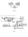
- Fig. 7 is a detailed structural diagram of a process control system in an embodiment of the present invention.
- the system comprises two parts, namely a controller end and a wireless sensor end.
- the wireless sensor end collects process parameters of a production process according to a sampling frequency, and sends the collected process parameters to the controller end according to a transmission frequency, wherein the sampling frequency is higher than the transmission frequency. For example: assume that the sampling frequency is 2 seconds, and the transmission frequency is 20 seconds.
- the wireless sensor end comprises a sample and hold device, a comparator, a summator and an aggregator.
- the workflow of the wireless sensor end is as follows:
- a summation operation is performed in the summator, to obtain a control quantity correction value (ED).
- the controller end comprises a gateway, a first comparator, a PID controller and a second comparator; the gateway receives the control quantity correction value (ED) and process parameter sent by the wireless sensor end at intervals of 20 s.
- the process parameter is sent to the first comparator, for comparison with a preset set value (set point); the difference value is sent to the PID controller, to obtain a control variable initial value.
- the difference between the control variable initial value and a preset function of the control quantity correction value (ED) is found, to obtain a control variable value; the control variable value (MV) can be used to control the production process.
- MV MV ⁇ + K c ⁇ e t + 1 ⁇ I ⁇ ⁇ 0 t ⁇ e t ⁇ dt - ED ;
- K c is a scale factor
- ⁇ I is an integration constant
- the two parameters K c and ⁇ I can be set by the user
- e(t) is the difference between the set point and the process parameter
- t is time.
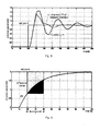
- Fig. 8 is a schematic diagram comparing the control performances of an embodiment of the present invention with the prior art
- Fig. 9 is a schematic diagram showing the improvement in control performance in an embodiment of the present invention.
- the control method in the embodiments of the present invention has a smaller overswing and a shorter transition time than in the prior art, so the control performance is improved significantly.
- the advantage of the embodiments of the present invention lies in the additional information of multiple measurement values provided between transmission periods. To a certain extent, the embodiments of the present invention compensate for information that is lost because the sampling interval is too long.
- MV MV ⁇ + K c ⁇ e t + 1 ⁇ I ⁇ ⁇ 0 t ⁇ e t ⁇ dt .
- this proportional-integral formula may introduce significant oscillation.
- Fig. 9 shows, between transmission moments t1 and t2, an existing PI controller assumes that the control variable and e(t) are fixed; the actual control variable is close to the set point.
- repeatedly calculated integral operations are corrected by subtracting ED in the next control period. By way of obtaining the actual difference value signal between the set point and the control variable, frequently obtained control variable measurement values make a contribution to improvement of control performance.
- Embodiments of the present invention can be applied in a variety of specific field environments.
- the system shown in Fig. 7 may be specifically applied in microalgal culture processing.
- the production process in Fig. 7 is a photobioreactor for microalgal culture.
- a wireless PH sensor communicates with a controller once every 300 seconds, and the wireless PH sensor gives an additional measurement value every 30 seconds. Every 300 seconds, all the measurement values are formed into a package and sent to the controller.
- the PH set point is 7.0, a value which is beneficial to microalgae.
- the controller may use a PI control algorithm, and may use a variety of existing control techniques, for example output restriction, etc.
- the control variable (MV) is the feeding speed at which carbon dioxide (CO 2 ) is inputted to the photobioreactor.
- Multiple PH measurement values are formed into a package as initial data and sent to the control system, and an ED is generated in the controller.
- the ED can also be generated in the wireless sensor, and the ED and control parameter can be sent together to the controller.
- the controller extracts the ED value in the PI integral calculation.
- the process control method proposed in the embodiments of the present invention can be stored on a variety of machine-readable storage media by an instruction or instruction set storage method.
- These storage media include but are not limited to: floppy disk, optical disk, DVD, hard disk, flash memory, USB flash drive, CF card, SD card, MMC card, SM card, memory stick, xD card, etc.
- the process control method proposed in the embodiments of the present invention may also be applied in flash memory (Nand flash) storage media, such as USB flash drive, CF card, SD card, SDHC card, MMC card, SM card, memory stick, xD card, etc.
- the process control method proposed in the embodiments of the present invention may also be specifically implemented as computer instructions in a variety of forms. When these computer instructions are executed in a machine, they can make the machine execute the process control method proposed in the embodiments of the present invention.
- the embodiments of the present invention comprise a wireless sensor and a controller, wherein: the wireless sensor is used for collecting process parameters of a production process according to a sampling frequency, obtaining a control quantity correction value according to process parameters collected in a data collection period, and sending the collected process parameters and the calculated control quantity correction value to the controller according to a transmission frequency, wherein the sampling frequency is higher than the transmission frequency; the controller is used for calculating a control variable initial value according to the process parameters sent and obtaining a variable value according to the control variable initial value and the control quantity correction value sent by the wireless sensor, and using the control variable value to control the production process.
Landscapes
- Physics & Mathematics (AREA)
- General Physics & Mathematics (AREA)
- Engineering & Computer Science (AREA)
- Automation & Control Theory (AREA)
- Arrangements For Transmission Of Measured Signals (AREA)
- Mobile Radio Communication Systems (AREA)
Applications Claiming Priority (1)
| Application Number | Priority Date | Filing Date | Title |
|---|---|---|---|
| PCT/CN2013/071220 WO2014117371A1 (zh) | 2013-01-31 | 2013-01-31 | 一种过程控制方法、装置和系统 |
Publications (2)
| Publication Number | Publication Date |
|---|---|
| EP2952980A1 true EP2952980A1 (de) | 2015-12-09 |
| EP2952980A4 EP2952980A4 (de) | 2016-10-19 |
Family
ID=51261424
Family Applications (1)
| Application Number | Title | Priority Date | Filing Date |
|---|---|---|---|
| EP13874187.1A Withdrawn EP2952980A4 (de) | 2013-01-31 | 2013-01-31 | Prozesssteuerungsverfahren, -vorrichtung und -system |
Country Status (3)
| Country | Link |
|---|---|
| EP (1) | EP2952980A4 (de) |
| CN (1) | CN104781737A (de) |
| WO (1) | WO2014117371A1 (de) |
Families Citing this family (2)
| Publication number | Priority date | Publication date | Assignee | Title |
|---|---|---|---|---|
| CN108491558A (zh) * | 2018-01-17 | 2018-09-04 | 南京航空航天大学 | 机翼扑动频率始终不变的扑翼飞行器的设计和控制方法 |
| CN108684008B (zh) * | 2018-05-15 | 2023-12-29 | 北京国科舰航传感技术有限公司 | 无线传感器、无线传感系统以及无线传感方法 |
Family Cites Families (12)
| Publication number | Priority date | Publication date | Assignee | Title |
|---|---|---|---|---|
| JPH07104681B2 (ja) * | 1988-03-18 | 1995-11-13 | 株式会社東芝 | プロセス制御装置 |
| US7860495B2 (en) * | 2004-08-09 | 2010-12-28 | Siemens Industry Inc. | Wireless building control architecture |
| US7620460B2 (en) * | 2005-10-25 | 2009-11-17 | Fisher-Rosemount Systems, Inc. | Process control with unreliable communications |
| US7587252B2 (en) * | 2005-10-25 | 2009-09-08 | Fisher-Rosemount Systems, Inc. | Non-periodic control communications in wireless and other process control systems |
| JP4083767B2 (ja) * | 2005-12-22 | 2008-04-30 | ファナック株式会社 | サーボモータを制御する数値制御装置 |
| DE102005062579A1 (de) * | 2005-12-27 | 2007-07-05 | Siemens Ag | Vorrichtung zum drahtlosen Datenaustausch sowie Verfahren zum Aufbau einer drahtlosen Verbindung zwischen einer insbesondere medizinischen Sensoreinheit und einer Rechnereinheit |
| EP1995653A1 (de) * | 2007-05-22 | 2008-11-26 | Abb Research Ltd. | System zur Steuerung eines Automatisierungsprozesses |
| CN100478817C (zh) * | 2007-06-28 | 2009-04-15 | 济南西格马科技有限公司 | 能够远程实时监控振动时效工艺过程的方法及其装置 |
| US8112381B2 (en) * | 2007-11-02 | 2012-02-07 | Siemens Corporation | Multivariate analysis of wireless sensor network data for machine condition monitoring |
| CN101256400B (zh) * | 2008-04-09 | 2010-06-02 | 清华大学 | 一种延迟焦化炉的控制方法 |
| US20120215326A1 (en) * | 2011-02-17 | 2012-08-23 | Invensys Systems Inc. | Distributed Proportional/Integral/Derivative Tuning |
| CN102186309B (zh) * | 2011-03-22 | 2013-03-20 | 鞍山市正发电路有限公司 | 激光直接成像全印刷电路 |
-
2013
- 2013-01-31 WO PCT/CN2013/071220 patent/WO2014117371A1/zh not_active Ceased
- 2013-01-31 CN CN201380058026.5A patent/CN104781737A/zh active Pending
- 2013-01-31 EP EP13874187.1A patent/EP2952980A4/de not_active Withdrawn
Also Published As
| Publication number | Publication date |
|---|---|
| EP2952980A4 (de) | 2016-10-19 |
| WO2014117371A1 (zh) | 2014-08-07 |
| CN104781737A (zh) | 2015-07-15 |
Similar Documents
| Publication | Publication Date | Title |
|---|---|---|
| JP6259706B2 (ja) | ワイヤレスプロセス制御装置からの伝送を減少するためのシステム及び方法 | |
| CN102541013B (zh) | 阳极保护设备远程监控、预警及故障诊断系统与方法 | |
| US9391495B2 (en) | Predicting motor failure based on relationship of motor pair characteristics | |
| WO2011002800A3 (en) | Methods and arrangements for in-situ process monitoring and control for plasma processing tools | |
| WO2013005027A3 (en) | Apparatus and methods for monitoring and analysing the performance of a heating or cooling system | |
| CN115407731A (zh) | 生产线工作状态监测与故障预警系统和方法 | |
| CN104535735B (zh) | 水质远程在线监测方法 | |
| CN117387724B (zh) | 一种高精度液位遥测报警系统 | |
| CN101520856A (zh) | 基于kkt条件和最近邻法的支持向量回归机自适应建模方法 | |
| CN110493884A (zh) | 一种低功耗监测数据无线采集系统和方法 | |
| EP2952980A1 (de) | Prozesssteuerungsverfahren, -vorrichtung und -system | |
| JP2015226423A (ja) | 異常判定装置、異常判定方法、及びコンピュータプログラム | |
| CN116242426B (zh) | 一种大跨度空间结构健康监管系统及其方法 | |
| AU2021103530A4 (en) | Sensor System | |
| US20220012821A1 (en) | Prediction of a wind farm energy parameter value | |
| CN104568195A (zh) | 功能安全温度变送器 | |
| CN203761429U (zh) | 一种基于物联网技术的智能电网监控系统 | |
| JP2020106916A (ja) | 監視事象解析装置の設定方法 | |
| CN106817165A (zh) | 基于光通信唤醒的光纤网络式传感器、光纤网络式传感器监测系统及其监测方法 | |
| US20160154387A1 (en) | Function unit, analog input unit, and programmable controller system | |
| US20140028466A1 (en) | Method and server for monitoring energy source | |
| CN205356700U (zh) | 一种无线传感网络系统 | |
| CN114994361B (zh) | 一种基于动态能谱的工程对象健康状态监测装置及其方法 | |
| CN202634704U (zh) | 基于无线组网量值传递的传感器原位在线校准系统 | |
| Trigona et al. | Study of Energy Consumption and Performance in an Autonomous Sensor Node with On-Demand Communication and Wake-Up Receiver as a Function of Computational Complexity |
Legal Events
| Date | Code | Title | Description |
|---|---|---|---|
| PUAI | Public reference made under article 153(3) epc to a published international application that has entered the european phase |
Free format text: ORIGINAL CODE: 0009012 |
|
| 17P | Request for examination filed |
Effective date: 20150617 |
|
| AK | Designated contracting states |
Kind code of ref document: A1 Designated state(s): AL AT BE BG CH CY CZ DE DK EE ES FI FR GB GR HR HU IE IS IT LI LT LU LV MC MK MT NL NO PL PT RO RS SE SI SK SM TR |
|
| AX | Request for extension of the european patent |
Extension state: BA ME |
|
| DAX | Request for extension of the european patent (deleted) | ||
| A4 | Supplementary search report drawn up and despatched |
Effective date: 20160915 |
|
| RIC1 | Information provided on ipc code assigned before grant |
Ipc: G05B 11/36 20060101AFI20160909BHEP |
|
| RAP1 | Party data changed (applicant data changed or rights of an application transferred) |
Owner name: SIEMENS AKTIENGESELLSCHAFT |
|
| STAA | Information on the status of an ep patent application or granted ep patent |
Free format text: STATUS: REQUEST FOR EXAMINATION WAS MADE |
|
| STAA | Information on the status of an ep patent application or granted ep patent |
Free format text: STATUS: THE APPLICATION IS DEEMED TO BE WITHDRAWN |
|
| 18D | Application deemed to be withdrawn |
Effective date: 20180801 |