EP2952984A2 - Procédé de réglage de fonctionnalités d'un dispositif de surveillance de situation et installation de bâtiment - Google Patents
Procédé de réglage de fonctionnalités d'un dispositif de surveillance de situation et installation de bâtiment Download PDFInfo
- Publication number
- EP2952984A2 EP2952984A2 EP15158942.1A EP15158942A EP2952984A2 EP 2952984 A2 EP2952984 A2 EP 2952984A2 EP 15158942 A EP15158942 A EP 15158942A EP 2952984 A2 EP2952984 A2 EP 2952984A2
- Authority
- EP
- European Patent Office
- Prior art keywords
- programming
- situation
- situation monitor
- marker
- sensor
- Prior art date
- Legal status (The legal status is an assumption and is not a legal conclusion. Google has not performed a legal analysis and makes no representation as to the accuracy of the status listed.)
- Granted
Links
Images


Classifications
-
- G—PHYSICS
- G05—CONTROLLING; REGULATING
- G05B—CONTROL OR REGULATING SYSTEMS IN GENERAL; FUNCTIONAL ELEMENTS OF SUCH SYSTEMS; MONITORING OR TESTING ARRANGEMENTS FOR SUCH SYSTEMS OR ELEMENTS
- G05B19/00—Program-control systems
- G05B19/02—Program-control systems electric
- G05B19/04—Program control other than numerical control, i.e. in sequence controllers or logic controllers
- G05B19/042—Program control other than numerical control, i.e. in sequence controllers or logic controllers using digital processors
-
- G—PHYSICS
- G05—CONTROLLING; REGULATING
- G05B—CONTROL OR REGULATING SYSTEMS IN GENERAL; FUNCTIONAL ELEMENTS OF SUCH SYSTEMS; MONITORING OR TESTING ARRANGEMENTS FOR SUCH SYSTEMS OR ELEMENTS
- G05B15/00—Systems controlled by a computer
- G05B15/02—Systems controlled by a computer electric
-
- G—PHYSICS
- G05—CONTROLLING; REGULATING
- G05B—CONTROL OR REGULATING SYSTEMS IN GENERAL; FUNCTIONAL ELEMENTS OF SUCH SYSTEMS; MONITORING OR TESTING ARRANGEMENTS FOR SUCH SYSTEMS OR ELEMENTS
- G05B2219/00—Program-control systems
- G05B2219/20—Pc systems
- G05B2219/23—Pc programming
- G05B2219/23363—Barcode
-
- G—PHYSICS
- G05—CONTROLLING; REGULATING
- G05B—CONTROL OR REGULATING SYSTEMS IN GENERAL; FUNCTIONAL ELEMENTS OF SUCH SYSTEMS; MONITORING OR TESTING ARRANGEMENTS FOR SUCH SYSTEMS OR ELEMENTS
- G05B2219/00—Program-control systems
- G05B2219/20—Pc systems
- G05B2219/26—Pc applications
- G05B2219/2642—Domotique, domestic, home control, automation, smart house
-
- G—PHYSICS
- G05—CONTROLLING; REGULATING
- G05B—CONTROL OR REGULATING SYSTEMS IN GENERAL; FUNCTIONAL ELEMENTS OF SUCH SYSTEMS; MONITORING OR TESTING ARRANGEMENTS FOR SUCH SYSTEMS OR ELEMENTS
- G05B2219/00—Program-control systems
- G05B2219/30—Nc systems
- G05B2219/35—Nc in input of data, input till input file format
- G05B2219/35444—Gesture interface, controlled machine observes operator, executes commands
Definitions
- the invention relates to a method for setting functionalities of a situation monitor, in particular a situation monitor, which detects or records its monitoring area in a multi-dimensional manner. Described is further a building installation with a situation monitor and at least one controlled by this actuator.
- Building services installation systems may include a variety of different actuators.
- Actuators in the context of these embodiments are any of a control unit controllable components of a building installation system. Thus, for example, these are also interfaces, for example communication interfaces in addition to the usual actuators such as room lighting, shading devices or the like.
- Building installations, such as a room lighting, a shading device or the like are controlled in many cases depending on the situation. In a shading device, such as a blind device, this can be set up depending on the incident sunlight.
- Presence detectors are used to control room lighting, which controls the room lighting and thus the one or more lights as actuators or actuators when the presence of one or more persons in the room is detected, for example when entering.
- situation monitors In addition to situation monitors, as described above, those are also used with which the surveillance area is detected in two dimensions. With such situation monitors a spatially resolved detection within the surveillance area is possible. The resolution in the detection of the monitoring area depends on the resolution of the sensor associated with the situation monitor. In the case of a situation monitor with spatially resolved detection of its monitoring area, the sensor is generally designed as an area sensor. This can be, for example, a camera sensor. Such situation monitors allow a much more detailed detection of the monitoring area associated therewith. If with such situation monitors a spatially resolved detection is to be made, for example a Subdivision of his surveillance area into two or more sections, which can also be evaluated independently, this requires a corresponding device of the situation monitor, which is typically done in connection with its commissioning.
- such a situation monitor which covers its monitoring area in a multi-dimensional manner, will be connected to a building installation bus.
- a device of the situation monitor in order to allocate certain functionalities to this, takes place with the software used for setting up the bus system or its participants. This means that a person wishing to set up the situation monitor must have access to the building installation bus via an existing bus interface. Such work can only be done by appropriately trained people. The same applies to a device of the situation monitor at an interface assigned to the situation monitor. Devices of devices of the type described above are usually performed by service providers. In some cases, however, third parties may not be allowed access to the entire building installation bus to set up such a situation monitor, for example, when building installations connected to the installation bus are also installations with possibly sensitive information. Sometimes it is also desired that a person performing the device of the situation monitor not be informed of the monitoring function of the situation monitor and in particular its resolution and that the device can also be made by persons who are untrained with respect to a set-up software.
- the object of the invention is therefore to propose a method for setting functionalities of a situation guard within the framework of a building installation, with which not only the desired arrangement can be carried out by people who are not experienced in handling typically used installation software but also in the case of such an attitude the data obtained with the situation monitor, for example the captured image of the surveillance area, of the person performing the device is not needed for the purpose of setting up the situation watcher.
- the invention has for its object to propose a building installation with a suitably designed situation monitor.
- the building installation-related task is solved by a building installation with a situation monitor comprising a multidimensionally monitoring his monitoring area sensor and an evaluating the sensor data serving control unit and with at least one controllable by the control unit of the situation monitor actuator which situation monitor via a programming interface to its parameterization and / or his Control can be identified by the within the monitoring range of the sensor placed and detected by a situation detection program marker with respect to a programming code detected and evaluated.
- a situation monitor comprising a multidimensionally monitoring his monitoring area sensor and an evaluating the sensor data serving control unit and with at least one controllable by the control unit of the situation monitor actuator which situation monitor via a programming interface to its parameterization and / or his Control can be identified by the within the monitoring range of the sensor placed and detected by a situation detection program marker with respect to a programming code detected and evaluated.
- the multi-dimensional and thus at least two-dimensional spatially resolved detection of the surveillance area is used by the situation monitor as a programming interface.
- the programming or the program commands are provided by programming markers.
- Such a programming marker carries a programming code.
- such a programming marker can be a film printed with the programming code or cardboard printed with such a code.
- the programming code can be in Depending also on the resolution of the sensor of the situation monitor be simple or complex. If the programming code is very simple, the programming marker as such represents the programming code. This is therefore a 1-bit programming code. The size and / or the geometry of such a programming marker then represents the programming code. If a more complex programming code is provided, such a programming marker carries a programming code which is to be resolved with regard to its geometry, thus an x-bit programming code.
- At least one such programmer marker is placed within its surveillance area for the purpose of programming the situation monitor.
- a programming marker and the programming code thereon extend over at least a few pixels of the typically used area sensor which is used to spatially detect the surveillance area within its resolution.
- the complexity of the programming codes and the resolution of the sensor are matched. Finally, the latter must be able to identify the code and distinguish it from others.
- the data obtained by the situation monitor's sensor as part of a situation detection can then be evaluated with regard to an identification of the detected programming marker with its programming code.
- a predefined routine such as a calculation routine, a control routine, or the like.
- the execution of the detected command may be performed in the situation monitor control unit or, in the event that the situation monitor is connected to a communication medium, by another arithmetic unit that is part of the communication medium, such as a data bus.
- the situation monitor will be designed in such a way that the evaluation of the data recorded with its sensor is carried out in the control unit of the situation monitor.
- An implementation of the detected command can be done by the control unit of the situation monitor or else elsewhere.
- a calculation routine can be used to determine the location of the Detection of the programming marker and a direction information contained therein to subdivide the monitoring area into several individual sub-areas make.
- an assignment of specific pixel areas of the sensor to the monitoring area subdivision provided by the code contained on the programming marker takes place.
- the pixels assigned to a monitoring subarea can then be read out and / or evaluated in relation to the desired monitoring subarea. Changes in a monitoring subarea can thus be detected more quickly, since not all pixels of the sensor, which is typically designed as an area sensor, must be read out during monitoring of a monitoring subarea, but only those which are assigned to a specific monitoring subarea.
- a subdivision can be made in a plurality of subareas and will make this depending on the design and use of the space.
- the programming code is equipped with direction information on which one or more subarea boundaries can be calculated on the situation monitor side.
- Direction information in or on such a programming marker can be transmitted to the situation monitor, for example, by coding having a preferred direction.
- Direction information may also be programmed by placing two spaced programmer markers at appropriate locations in the surveillance area. The direction information then results from the calculation of virtual connection lines and / or intersections.
- a programming marker can, for example, also contain information relating to the actuator (s) to be controlled by the situation monitor.
- the actuators are, for example, a plurality of luminaires or groups of luminaires, these can be assigned to different monitoring regions. For this it is necessary that the situation monitor knows the spatial position of the luminaires with respect to a subdivision of the surveillance area. Sometimes the actors will be those who are not themselves within the monitoring area of the situation guard are arranged. This is likely to be the case, for example, with ceiling lights, which are due to this arrangement outside the detection range of the sensor of the situation monitor.
- the arrangement of the luminaires can be communicated to the situation monitor by arranging corresponding programming markers in the projection of the luminaires into the surveillance area, for example on the floor of the room.
- other actuators outside the actual detection range of the situation monitor such as blinds.
- the situation monitor is to be used, that one or the other actuator is to be controlled by evaluating gestures of persons located in the monitoring area, knowledge of the spatial position of the actuators is required.
- the code contained on the programming marker (s) will preferably be interpreted in such a way that it makes itself noticeably noticeable on the image acquired by the sensor of the situation monitor, and thus clearly differs from its surroundings. This reduces the effort of an evaluation of the data obtained by the sensor of the situation monitor for the purpose of identifying a programming code.
- the code with the greatest possible contrast to the usual detected. For example, if the situation monitor sensor is an infrared sensor (IR sensor), this contrast can be provided between the programmer's programmer programming code and the programming marker placement environment by passing the code provided by a programmer IR light is formed totally reflecting and / or absorbed areas.
- IR sensor infrared sensor
- a code of a programming marker detected in the context of a situation detection can be identified by a simple pattern comparison even with relatively low evaluation resources.
- Surfaces that totally reflect IR light and those that absorb IR light are well known. Is exploited in such a concept that typically in the detection range neither totally IR light totally absorbing IR light totally absorbing areas are not present, at least not in an arrangement to each other, as provided by the code.
- the situation monitor can be switched to a programming mode beforehand. However, this is not absolutely necessary, but may be useful for some programming.
- the switching of the situation monitor into its programming mode can also be undertaken with such a programming marker carrying a corresponding programming code. This is placed in its monitoring area during the operation mode of the situation monitor. If the situation monitor has detected and identifies this programming marker with the code thereon, this is switched to its programming mode in the execution of the command contained by the code.
- the situation monitor can also be switched in other ways in its programming mode, for example by a button located on the device or by a button arranged on the wall side.
- a signal light e.g., LED
- the situation monitor is in this mode, typically the otherwise executed evaluation for monitoring the monitoring area is interrupted or switched off.
- the evaluation of the data acquired by the situation monitor alone may be limited to a pattern comparison of the possible codes contained on programming markers. The evaluation and identification of the codes contained on the programming marker are correspondingly faster.
- the situation monitor is programmed in a programming mode, it is terminated by a specific command after the desired programming has been completed.
- a command can be generated on the situation monitor side if within a predetermined time interval no situation has been detected in which either existing programming markers have been changed in position and / or new programming markers have been placed.
- the programming mode can also be terminated by arranging a programming marker with a corresponding programming code within the monitoring area of the situation monitor.
- the surveillance area is three-dimensional
- To capture the code of a programming marker can also be constructed in three dimensions. Accordingly, in such an embodiment, a pattern comparison takes place with respect to this situational wise known three-dimensional patterns.
- the situation monitor Since the situation monitor detects its monitoring area at least two-dimensionally, it can, if appropriately configured, be used to control actuators actuated by the situation monitor by means of gestures. As a result of a two-dimensional detection, certain gestures can be evaluated as indicated directions, for example by an outstretched arm of a person located in the surveillance area. If this gesture, so for example, the extended arm points in the direction of an actuator, this can be controlled via this gesture. If the actuator is, for example, a luminaire, or if the gesture, for example the outstretched arm, is in the direction in which the luminaire is projected onto the monitoring plane, this can be controlled via a predetermined dimming routine.
- This dimming routine for example, according to which, for example, a cyclical brightening and darkening is passed through, is terminated according to an exemplary embodiment, when the gesture is no longer detected, ie: for example, the outstretched arm is no longer stretched out or has changed its direction.
- actuators can also be controlled by successive gestures.
- Corresponding routines minimize faulty control. For example, it may be provided that in such a control, the actuator is only triggered when the gesture is maintained for longer than a predefined time interval, for example a few seconds.
- Three-dimensional sensors can be realized, for example, by a stereo camera sensor with two individual, spaced-apart sensors. However, a configuration in which only one area sensor is required is preferred. This is possible, for example, with an infrared sensor having a group of IR light-emitting LEDs and a two-dimensional array of IR-sensitive optoelectronic transducer elements. Then, the depth information can be obtained over the term of the light-emitting diode (s) to the sensor array. This evaluation is commonly referred to as a time-of-flight evaluation. Other concepts can also be realized, such as the principle of "structured light".
- IR-absorbing areas are represented as areas having a depth extent of "undefined” or “zero”, while IR-light totally reflecting areas indicate the actual distance to the sensor.
- a lighting device is installed as a building installation.
- the lighting device comprises four ceiling lights L 1 to L 4 .
- the ceiling lights L 1 to L 4 are divided into two lighting groups LG 1 , LG 2 .
- a first lighting group LG 1 is formed by the lights L 1 and L 2 .
- a second lighting group LG 2 is provided by the lights L 3 and L 4 .
- the lights L 1 to L 4 are connected to an installation bus 2.
- the installation bus 2 is not limited to the lights L 1 to L 4 and the other, yet to be described components, but part of a pulling through the entire building bus system.
- the lighting device as a building installation is assigned a situation monitor 3 in addition to the lights L 1 to L 4 .
- the situation monitor 3 comprises a sensor 4 and a control unit 5.
- the control unit 5 evaluates the data obtained via the sensor 4 and controls the lighting groups LG 1 , LG 2 as a function of the evaluation result.
- the sensor 4 is an infrared surface sensor, which in turn has an IR diode array and an area sensor subdivided into individual optoelectric transducer elements (pixels). The sensor 4 is controlled via the control unit 5.
- the sensor 4 can be operated as a 3D sensor, namely by evaluating the time required for an emitted IR pulse until it is detected by one or more pixels of the sensor array when it is reflected by an object located in the monitoring area 6.
- the Runtime is proportional to the distance covered by the IR pulse and therefore includes distance information.
- the surveillance area 6 can be detected three-dimensionally and thus in the manner of a depth map.
- the situation monitor 3 is designed so that it can be programmed. This is used, among other things, in connection with its commissioning.
- the situation monitor 3 can be programmed and thus adjusted with regard to one or more of its functionalities by utilizing its optical detection properties, which in this context are used as an optical programming interface. For such optical programming, access to the installation bus 2 or otherwise to the control unit 5 of the situation monitor 3 is not required.
- the situation monitor 3 is switched to a programming mode for its optical programming. This is not essential, but is done in this embodiment.
- the situation monitor 3 In its programming mode, the situation monitor 3 is switched by arranging a first programming marker in the monitoring area 6.
- a programming marker carries a specific code, also known as a programming code, which in the embodiment described is formed by a specific pattern of signal totally absorbing (or substantially totally absorbing) and signal totally reflecting (or largely totally reflecting) surface areas.
- the acquired image is regularly examined for the detection of this code by a pattern comparison. If such a code is identified, the situation monitor 3 switches to its programming mode. In this mode, an evaluation of the sensor data takes place in relation to an identification of possible further programming codes.
- programming markers are arranged in the monitoring area 6, typically on the floor 7 of the room 1, each carrying a programming code.
- commands in this way can be arranged one after the other or even several apart from each other on the floor 7 in order to be recorded with a single situation detection to become.
- FIG. 2 shows an example of an arrangement of a programming marker 8.
- the programming marker 8 is located approximately in the middle between the two lighting groups LG 1 , LG 2 with a small distance to the rear room wall.
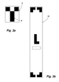
- the code printed on the programming marker 8 is shown in an enlarged view in FIG FIG. 3a shown. This over several pixels of the sensor 4 extending code is T-shaped. As a result, the code includes a direction information, namely, that the longer leg 9 faces the opposite wall.
- the detection of the code of the programming marker 8 causes the monitoring area 6 in the alignment of the leg 9 is divided into two monitoring sections 10, 11.
- the dividing line between the subregions 10, 11 is in FIG. 2 shown in phantom. This line represents the track of the dividing plane which also extends in the vertical direction.
- the division of the surveillance area 6 into the two partial areas 10, 11 corresponds to the arrangement of the two lighting groups LG 1 , LG 2 , so that the lighting group LG 1 formed by the lights L 1 and L 2 in the monitoring area 10 and the lights L 3 and L 4 formed lighting group LG 2 are arranged in the monitoring portion 11.
- This programming of the situation monitor 3 described by way of example is carried out so that, depending on the situation, the lighting group belonging to the partial area 10 and / or the partial area 11 can be controlled.
- the aim of this device is that the lights of those lighting group are controlled, in whose monitoring section 10 or 11 there are one or more people in the room 1 people.
- the lighting group LG 2 is dimmed down in this example, while the lighting group LG 1 is brightened.
- the situation monitor 3 actuators that are controlled depending on the partial occupancy in the room 1, such as a shading device.
- a person detection takes place with the situation monitor 4 by his ability to detect objects / subjects three-dimensionally in his surveillance area 6 and in this way also persons of others, to distinguish in the space 1 located objects.
- an evaluation of the data obtained with the situation monitor 3 can be limited to moving or moving objects.
- Stationary objects can be eliminated by a filtering process, for example a difference image analysis, so that such an evaluation is possible even without large computing resources.
- the situation monitor 3 switches this in the illustrated embodiment automatically back into its monitoring mode, namely, if after a certain period of time, for example, 30 seconds no change in the positioning of the position marker 8 or the addition of a or several other programming markers has been detected.
- the situation monitor 3 has initially only been set up with respect to a functionality, in this case the setting up of monitoring subregions. It is understood that different functionalities of the situation monitor 3 can be set up in the same way.
- the situation monitor 3 can also be programmed, for example, with additional position data, for example the arrangement of the luminaires L 1 to L 4 on the ceiling. These are how out FIG. 1 recognizable outside the monitoring area 6 of the situation monitor 3.
- To the situation monitor 3 to communicate the positioning of the lights L 1 to L 4 proceeding in an analogous manner, as this is done to the above-described programming for surveillance division.
- corresponding programming markers 12 are placed in the projection of the lights L 1 to L 4 on the floor 7 of the room 1.
- FIG. 3b shows in an enlarged view such a programming marker 12.
- the code contained thereon consists of angles, each representing a corner of the respective lamp L 1 to L 4 .
- the direction information contained in the angles allows a calculation of the outline of the respective lamp.
- part of the programming code is an "L".
- the situation monitor 3 is informed that the respective luminaire L 1 to L 4 is a linear luminaire is.
- dashed lines below the "L” a crossbar is shown as a possible additional code. This could be used as further information, if available, to inform the situation monitor 3 that the respective luminaire is a pendant luminaire. In the illustrated embodiment, it is in the lamp L 1 -so in the lights L 2 to L 4 - ceiling recessed lights.
- the spatial position of the same is needed because by means of the situation monitor 3 also a gesture control each light group LG 1 , LG 2 is provided.
- the system uses the possible depth detection of objects in the surveillance area by the situation monitor 3.
- the gesture control in this embodiment is provided in such a way that the outstretched arm 14 of a person 15 located in the monitoring area 6, if directed at one of the two lighting groups LG 1 , LG 2 for at least a predefined period of time (for example 3 seconds), activates the latter same leads.
- a predefined period of time for example 3 seconds
- the enveloping bodies are in FIG. 1 identified by the reference numerals 13, 13.1.
- the cuboids are virtual cuboids which enclose the respective lights L 1 , L 2 or L 3 , L 4 of a lighting group LG 1 , LG 2 .
- the cuboids are typically larger both in their width extension and in their longitudinal extent than the space actually occupied by the two luminaires of a lighting group LG 1 , LG 2 (see FIG FIG. 1 ).
- the information can be used, whether the luminaires are ceiling-mounted luminaires, recessed ceiling luminaires or pendant luminaires.
- the vector V calculated via the outstretched arm 14 strikes the enveloping body 13.
- programming markers 8, 12 are exemplary.
- the programming code contained thereon can also be designed differently, in particular more complex.
- the representation of the programmer markers with their bright, signal total reflecting areas and with their dark, signal totally absorbing areas allow easy detection of the same in a recorded by the situation monitor 3 record. If the background on which the programming markers 8, 12 are placed has approximately signal-absorbing properties, it would be advisable to leave a larger edge area between the darker code areas and the edge of the respective programming markers 8, 12.
- both lighting groups LG 1 , LG 2 are controlled simultaneously.
- Such a luminaire control can result in a simple switching on and off of the respective luminaire group LG 1 , LG 2 , starting in each case from the current state. It is also quite possible that the holding of the outstretched arm after detection of the control request triggers a dimming cycle, according to which the lights of a lighting group LG 1 , LG 2 are dimmed cyclically from the current position up and down. If the arm of the activating person is lowered again, the dimming cycle ends with the currently set value.
- the above-described lighting control is to be understood as an example. According to another embodiment, it is provided that the arm is moved in the manner of a pointer in one or the other direction, and the arm movement defines the dimming process.
- the configuration of the sensor with its surface and depth detection can be done both a change in control by raising and lowering the arm and by pivoting the arm.
- a combined arm movement is possible due to the 3D detection of the monitoring area for programming or control of the situation monitor.
- the lighting group LG 1 For the LG 1 lighting group, for example, lifting and lowering the outstretched Poor the lights L 1 , L 2 , the lighting group LG 1 are equally dimmed.
- a pivoting of the arm leads to a different control of the lights L 1 , L 2 of this lighting group LG. 1
- FIG. 5 shows in a further embodiment, two further programming markers 16 which are placed on the floor 7 of the room 1.
- the programming markers 16 are IR-light isosceles triangles.
- the programming markers 16 are two independently operable ones. These serve to define a monitoring portion 17, which is indicated by the dashed line. Only the programming markers 16 are detected by the sensor.
- the lengthening of the legs can be calculated as vectors on the system side. The intersection points of the vectors then represent the other two corner points of the desired monitoring subarea 17. With the programming markers 16, these represent the programming code due to their geometry. Programming can also be performed with other geometrically simple figures, for example circles, squares, rectangles, hexagons or the like become.
- the possibilities of programming are not limited to the functionalities described in the exemplary embodiment.
- a programming of the situation monitor can also affect all other functionalities.
Landscapes
- Engineering & Computer Science (AREA)
- Physics & Mathematics (AREA)
- General Physics & Mathematics (AREA)
- Automation & Control Theory (AREA)
- General Engineering & Computer Science (AREA)
- Burglar Alarm Systems (AREA)
- Fire Alarms (AREA)
- Alarm Systems (AREA)
- Circuit Arrangement For Electric Light Sources In General (AREA)
Applications Claiming Priority (1)
| Application Number | Priority Date | Filing Date | Title |
|---|---|---|---|
| DE102014107682.6A DE102014107682A1 (de) | 2014-06-02 | 2014-06-02 | Verfahren zum Einstellen von Funktionalitäten eines Situationswächters sowie Gebäudeinstallation |
Publications (3)
| Publication Number | Publication Date |
|---|---|
| EP2952984A2 true EP2952984A2 (fr) | 2015-12-09 |
| EP2952984A3 EP2952984A3 (fr) | 2015-12-23 |
| EP2952984B1 EP2952984B1 (fr) | 2019-09-11 |
Family
ID=52807545
Family Applications (1)
| Application Number | Title | Priority Date | Filing Date |
|---|---|---|---|
| EP15158942.1A Active EP2952984B1 (fr) | 2014-06-02 | 2015-03-13 | Procédé de réglage de fonctionnalités d'un dispositif de surveillance de situation et installation de bâtiment |
Country Status (2)
| Country | Link |
|---|---|
| EP (1) | EP2952984B1 (fr) |
| DE (1) | DE102014107682A1 (fr) |
Families Citing this family (1)
| Publication number | Priority date | Publication date | Assignee | Title |
|---|---|---|---|---|
| DE102016120816B4 (de) | 2016-11-02 | 2022-08-25 | Insta Gmbh | Elektrisches/elektronisches Steuergerät |
Family Cites Families (5)
| Publication number | Priority date | Publication date | Assignee | Title |
|---|---|---|---|---|
| US20090271004A1 (en) * | 2008-04-28 | 2009-10-29 | Reese Zecchin | Method and apparatus for ranging detection of gestures |
| DE102009016918A1 (de) * | 2009-04-08 | 2010-10-14 | Osram Gesellschaft mit beschränkter Haftung | Beleuchtungseinrichtung, Gebäude mit einer Beleuchtungseinrichtung und Verfahren zum Betreiben einer Beleuchtungseinrichtung |
| EP2462302A1 (fr) * | 2009-08-06 | 2012-06-13 | Nice S.p.A. | Procédé pour entrer des données ou des codes de programmation dans un dispositif de commande d'actionnement pour des obturateurs ou barrières à enroulement |
| EP2596408B1 (fr) * | 2010-07-22 | 2014-04-30 | Gira Giersiepen GmbH & Co. Kg | Système et procédé de traitement d'informations visuelles, auditives, olfactives et/ou haptiques |
| DE102010032761A1 (de) * | 2010-07-29 | 2012-02-02 | E:Cue Control Gmbh | Verfahren zur Steuerung einer Beleuchtungsanlage, Steuerung für eine Beleuchtungsanlage und Beleuchtungsanlage |
-
2014
- 2014-06-02 DE DE102014107682.6A patent/DE102014107682A1/de not_active Ceased
-
2015
- 2015-03-13 EP EP15158942.1A patent/EP2952984B1/fr active Active
Non-Patent Citations (1)
| Title |
|---|
| None |
Also Published As
| Publication number | Publication date |
|---|---|
| EP2952984B1 (fr) | 2019-09-11 |
| EP2952984A3 (fr) | 2015-12-23 |
| DE102014107682A1 (de) | 2015-12-03 |
Similar Documents
| Publication | Publication Date | Title |
|---|---|---|
| DE10000287B4 (de) | Vorrichtung und Verfahren zur Überwachung eines Erfassungsbereichs an einem Arbeitsmittel | |
| WO2018069341A1 (fr) | Surveillance d'objet par enregistrement d'image infrarouge et éclairage par impulsion infrarouge | |
| DE102007053812A1 (de) | Konfigurationsmodul für ein Videoüberwachungssystem, Überwachungssystem mit dem Konfigurationsmodul, Verfahren zur Konfiguration eines Videoüberwachungssystems sowie Computerprogramm | |
| WO2013075154A1 (fr) | Configuration d'appareils de commande de moyens d'éclairage | |
| WO2017137104A1 (fr) | Système domotique | |
| WO2012155997A1 (fr) | Système de commande d'automatisation domestique et procédé de commande d'un dispositif d'un système d'automatisation domestique | |
| DE102018003762A1 (de) | Überwachungsvorrichtung zum Überwachen eines durch Aufteilen eines Überwachungsbereichs festgelegten räumlichen Bereichs | |
| DE102016010284A1 (de) | Robotersystem, das einen Sichtsensor verwendet | |
| DE102017108781A1 (de) | Beleuchtungsvorrichtung und Beleuchtungssystem | |
| EP2952981B1 (fr) | Procédé de fonctionnement d'une installation de bâtiment dotée d'un contrôleur de situation et installation de bâtiment dotée d'un contrôleur de bâtiment | |
| EP2952984B1 (fr) | Procédé de réglage de fonctionnalités d'un dispositif de surveillance de situation et installation de bâtiment | |
| DE102018101162A1 (de) | Messsystem und Verfahren zur extrinsischen Kalibrierung | |
| EP3338609A1 (fr) | Procédé de commande d'au moins un dispositif d'éclairage et/ou d'au moins un dispositif d'obscurcissement dans un environnement de « maison intelligente » par un aspirateur hautement automatisé et aspirateur | |
| WO1998013745A2 (fr) | Zone d'interaction pour representation de donnees | |
| DE102019127826B4 (de) | Sicherer optoelektronischer Sensor und Verfahren zum Absichern eines Überwachungsbereichs | |
| EP2650851B1 (fr) | Dispositif d'automatisation de bâtiment | |
| DE102015220377B4 (de) | Verfahren und Vorrichtung zum Bestimmen einer Position eines mobilen Geräts in einem Raum, mobiles Gerät mit der Vorrichtung und Verwenden eines optischen Sensors zum Bestimmen einer Position eines mobilen Geräts in einem Raum | |
| DE102015218844A1 (de) | Verfahren zum Steuern einer Beleuchtungsvorrichtung und Beleuchtungssystem | |
| EP3599411A1 (fr) | Dispositif et procédé de génération et de surveillance d'une zone de sécurité dans une chambre de travail | |
| DE112021004783T5 (de) | Steuerung für ein unbemanntes fluggerät und speichermedium | |
| EP3970454B1 (fr) | Détection de l'agencement spatial de composants d'un système d'éclairage et association d'une adresse de fonctionnement respective | |
| DE102012103163A1 (de) | Vorrichtung zur Steuerung eines Gebäudeaggregats | |
| WO2020079227A1 (fr) | Procédé et dispositif d'entraînement d'un réseau neuronal artificiel et procédé de détermination d'une position d'un appareil d'entrée | |
| AT524647B1 (de) | System und verfahren zum bereitstellen von informationen über anwesenheit in einem raum | |
| DE102012218213B4 (de) | Verfahren zum Steuern eines Telemanipulationsroboters |
Legal Events
| Date | Code | Title | Description |
|---|---|---|---|
| PUAL | Search report despatched |
Free format text: ORIGINAL CODE: 0009013 |
|
| PUAI | Public reference made under article 153(3) epc to a published international application that has entered the european phase |
Free format text: ORIGINAL CODE: 0009012 |
|
| AK | Designated contracting states |
Kind code of ref document: A2 Designated state(s): AL AT BE BG CH CY CZ DE DK EE ES FI FR GB GR HR HU IE IS IT LI LT LU LV MC MK MT NL NO PL PT RO RS SE SI SK SM TR |
|
| AX | Request for extension of the european patent |
Extension state: BA ME |
|
| AK | Designated contracting states |
Kind code of ref document: A3 Designated state(s): AL AT BE BG CH CY CZ DE DK EE ES FI FR GB GR HR HU IE IS IT LI LT LU LV MC MK MT NL NO PL PT RO RS SE SI SK SM TR |
|
| AX | Request for extension of the european patent |
Extension state: BA ME |
|
| RIC1 | Information provided on ipc code assigned before grant |
Ipc: G05B 15/02 20060101ALI20151119BHEP Ipc: G05B 19/042 20060101AFI20151119BHEP |
|
| 17P | Request for examination filed |
Effective date: 20160122 |
|
| RBV | Designated contracting states (corrected) |
Designated state(s): AL AT BE BG CH CY CZ DE DK EE ES FI FR GB GR HR HU IE IS IT LI LT LU LV MC MK MT NL NO PL PT RO RS SE SI SK SM TR |
|
| RAP1 | Party data changed (applicant data changed or rights of an application transferred) |
Owner name: INSTA GMBH |
|
| GRAP | Despatch of communication of intention to grant a patent |
Free format text: ORIGINAL CODE: EPIDOSNIGR1 |
|
| STAA | Information on the status of an ep patent application or granted ep patent |
Free format text: STATUS: GRANT OF PATENT IS INTENDED |
|
| RIC1 | Information provided on ipc code assigned before grant |
Ipc: G05B 15/02 20060101ALI20190510BHEP Ipc: G05B 19/042 20060101AFI20190510BHEP |
|
| INTG | Intention to grant announced |
Effective date: 20190612 |
|
| RIN1 | Information on inventor provided before grant (corrected) |
Inventor name: NEUHAUS, DR.-ING. STEFAN Inventor name: DETZNER, PETER |
|
| GRAS | Grant fee paid |
Free format text: ORIGINAL CODE: EPIDOSNIGR3 |
|
| GRAA | (expected) grant |
Free format text: ORIGINAL CODE: 0009210 |
|
| STAA | Information on the status of an ep patent application or granted ep patent |
Free format text: STATUS: THE PATENT HAS BEEN GRANTED |
|
| AK | Designated contracting states |
Kind code of ref document: B1 Designated state(s): AL AT BE BG CH CY CZ DE DK EE ES FI FR GB GR HR HU IE IS IT LI LT LU LV MC MK MT NL NO PL PT RO RS SE SI SK SM TR |
|
| REG | Reference to a national code |
Ref country code: GB Ref legal event code: FG4D Free format text: NOT ENGLISH |
|
| REG | Reference to a national code |
Ref country code: CH Ref legal event code: EP |
|
| REG | Reference to a national code |
Ref country code: AT Ref legal event code: REF Ref document number: 1179255 Country of ref document: AT Kind code of ref document: T Effective date: 20190915 |
|
| REG | Reference to a national code |
Ref country code: DE Ref legal event code: R096 Ref document number: 502015010289 Country of ref document: DE Ref country code: IE Ref legal event code: FG4D Free format text: LANGUAGE OF EP DOCUMENT: GERMAN |
|
| REG | Reference to a national code |
Ref country code: NL Ref legal event code: MP Effective date: 20190911 |
|
| REG | Reference to a national code |
Ref country code: LT Ref legal event code: MG4D |
|
| PG25 | Lapsed in a contracting state [announced via postgrant information from national office to epo] |
Ref country code: LT Free format text: LAPSE BECAUSE OF FAILURE TO SUBMIT A TRANSLATION OF THE DESCRIPTION OR TO PAY THE FEE WITHIN THE PRESCRIBED TIME-LIMIT Effective date: 20190911 Ref country code: FI Free format text: LAPSE BECAUSE OF FAILURE TO SUBMIT A TRANSLATION OF THE DESCRIPTION OR TO PAY THE FEE WITHIN THE PRESCRIBED TIME-LIMIT Effective date: 20190911 Ref country code: BG Free format text: LAPSE BECAUSE OF FAILURE TO SUBMIT A TRANSLATION OF THE DESCRIPTION OR TO PAY THE FEE WITHIN THE PRESCRIBED TIME-LIMIT Effective date: 20191211 Ref country code: SE Free format text: LAPSE BECAUSE OF FAILURE TO SUBMIT A TRANSLATION OF THE DESCRIPTION OR TO PAY THE FEE WITHIN THE PRESCRIBED TIME-LIMIT Effective date: 20190911 Ref country code: HR Free format text: LAPSE BECAUSE OF FAILURE TO SUBMIT A TRANSLATION OF THE DESCRIPTION OR TO PAY THE FEE WITHIN THE PRESCRIBED TIME-LIMIT Effective date: 20190911 Ref country code: NO Free format text: LAPSE BECAUSE OF FAILURE TO SUBMIT A TRANSLATION OF THE DESCRIPTION OR TO PAY THE FEE WITHIN THE PRESCRIBED TIME-LIMIT Effective date: 20191211 |
|
| PG25 | Lapsed in a contracting state [announced via postgrant information from national office to epo] |
Ref country code: RS Free format text: LAPSE BECAUSE OF FAILURE TO SUBMIT A TRANSLATION OF THE DESCRIPTION OR TO PAY THE FEE WITHIN THE PRESCRIBED TIME-LIMIT Effective date: 20190911 Ref country code: ES Free format text: LAPSE BECAUSE OF FAILURE TO SUBMIT A TRANSLATION OF THE DESCRIPTION OR TO PAY THE FEE WITHIN THE PRESCRIBED TIME-LIMIT Effective date: 20190911 Ref country code: GR Free format text: LAPSE BECAUSE OF FAILURE TO SUBMIT A TRANSLATION OF THE DESCRIPTION OR TO PAY THE FEE WITHIN THE PRESCRIBED TIME-LIMIT Effective date: 20191212 Ref country code: LV Free format text: LAPSE BECAUSE OF FAILURE TO SUBMIT A TRANSLATION OF THE DESCRIPTION OR TO PAY THE FEE WITHIN THE PRESCRIBED TIME-LIMIT Effective date: 20190911 Ref country code: AL Free format text: LAPSE BECAUSE OF FAILURE TO SUBMIT A TRANSLATION OF THE DESCRIPTION OR TO PAY THE FEE WITHIN THE PRESCRIBED TIME-LIMIT Effective date: 20190911 |
|
| PG25 | Lapsed in a contracting state [announced via postgrant information from national office to epo] |
Ref country code: NL Free format text: LAPSE BECAUSE OF FAILURE TO SUBMIT A TRANSLATION OF THE DESCRIPTION OR TO PAY THE FEE WITHIN THE PRESCRIBED TIME-LIMIT Effective date: 20190911 Ref country code: EE Free format text: LAPSE BECAUSE OF FAILURE TO SUBMIT A TRANSLATION OF THE DESCRIPTION OR TO PAY THE FEE WITHIN THE PRESCRIBED TIME-LIMIT Effective date: 20190911 Ref country code: PL Free format text: LAPSE BECAUSE OF FAILURE TO SUBMIT A TRANSLATION OF THE DESCRIPTION OR TO PAY THE FEE WITHIN THE PRESCRIBED TIME-LIMIT Effective date: 20190911 Ref country code: RO Free format text: LAPSE BECAUSE OF FAILURE TO SUBMIT A TRANSLATION OF THE DESCRIPTION OR TO PAY THE FEE WITHIN THE PRESCRIBED TIME-LIMIT Effective date: 20190911 Ref country code: IT Free format text: LAPSE BECAUSE OF FAILURE TO SUBMIT A TRANSLATION OF THE DESCRIPTION OR TO PAY THE FEE WITHIN THE PRESCRIBED TIME-LIMIT Effective date: 20190911 Ref country code: PT Free format text: LAPSE BECAUSE OF FAILURE TO SUBMIT A TRANSLATION OF THE DESCRIPTION OR TO PAY THE FEE WITHIN THE PRESCRIBED TIME-LIMIT Effective date: 20200113 |
|
| PG25 | Lapsed in a contracting state [announced via postgrant information from national office to epo] |
Ref country code: SM Free format text: LAPSE BECAUSE OF FAILURE TO SUBMIT A TRANSLATION OF THE DESCRIPTION OR TO PAY THE FEE WITHIN THE PRESCRIBED TIME-LIMIT Effective date: 20190911 Ref country code: SK Free format text: LAPSE BECAUSE OF FAILURE TO SUBMIT A TRANSLATION OF THE DESCRIPTION OR TO PAY THE FEE WITHIN THE PRESCRIBED TIME-LIMIT Effective date: 20190911 Ref country code: IS Free format text: LAPSE BECAUSE OF FAILURE TO SUBMIT A TRANSLATION OF THE DESCRIPTION OR TO PAY THE FEE WITHIN THE PRESCRIBED TIME-LIMIT Effective date: 20200224 Ref country code: CZ Free format text: LAPSE BECAUSE OF FAILURE TO SUBMIT A TRANSLATION OF THE DESCRIPTION OR TO PAY THE FEE WITHIN THE PRESCRIBED TIME-LIMIT Effective date: 20190911 |
|
| REG | Reference to a national code |
Ref country code: DE Ref legal event code: R097 Ref document number: 502015010289 Country of ref document: DE |
|
| PLBE | No opposition filed within time limit |
Free format text: ORIGINAL CODE: 0009261 |
|
| STAA | Information on the status of an ep patent application or granted ep patent |
Free format text: STATUS: NO OPPOSITION FILED WITHIN TIME LIMIT |
|
| PG2D | Information on lapse in contracting state deleted |
Ref country code: IS |
|
| PG25 | Lapsed in a contracting state [announced via postgrant information from national office to epo] |
Ref country code: DK Free format text: LAPSE BECAUSE OF FAILURE TO SUBMIT A TRANSLATION OF THE DESCRIPTION OR TO PAY THE FEE WITHIN THE PRESCRIBED TIME-LIMIT Effective date: 20190911 Ref country code: IS Free format text: LAPSE BECAUSE OF FAILURE TO SUBMIT A TRANSLATION OF THE DESCRIPTION OR TO PAY THE FEE WITHIN THE PRESCRIBED TIME-LIMIT Effective date: 20200112 |
|
| 26N | No opposition filed |
Effective date: 20200615 |
|
| PG25 | Lapsed in a contracting state [announced via postgrant information from national office to epo] |
Ref country code: SI Free format text: LAPSE BECAUSE OF FAILURE TO SUBMIT A TRANSLATION OF THE DESCRIPTION OR TO PAY THE FEE WITHIN THE PRESCRIBED TIME-LIMIT Effective date: 20190911 |
|
| PG25 | Lapsed in a contracting state [announced via postgrant information from national office to epo] |
Ref country code: MC Free format text: LAPSE BECAUSE OF FAILURE TO SUBMIT A TRANSLATION OF THE DESCRIPTION OR TO PAY THE FEE WITHIN THE PRESCRIBED TIME-LIMIT Effective date: 20190911 |
|
| REG | Reference to a national code |
Ref country code: CH Ref legal event code: PL |
|
| REG | Reference to a national code |
Ref country code: BE Ref legal event code: MM Effective date: 20200331 |
|
| PG25 | Lapsed in a contracting state [announced via postgrant information from national office to epo] |
Ref country code: LU Free format text: LAPSE BECAUSE OF NON-PAYMENT OF DUE FEES Effective date: 20200313 |
|
| PG25 | Lapsed in a contracting state [announced via postgrant information from national office to epo] |
Ref country code: FR Free format text: LAPSE BECAUSE OF NON-PAYMENT OF DUE FEES Effective date: 20200331 Ref country code: LI Free format text: LAPSE BECAUSE OF NON-PAYMENT OF DUE FEES Effective date: 20200331 Ref country code: CH Free format text: LAPSE BECAUSE OF NON-PAYMENT OF DUE FEES Effective date: 20200331 Ref country code: IE Free format text: LAPSE BECAUSE OF NON-PAYMENT OF DUE FEES Effective date: 20200313 |
|
| PG25 | Lapsed in a contracting state [announced via postgrant information from national office to epo] |
Ref country code: BE Free format text: LAPSE BECAUSE OF NON-PAYMENT OF DUE FEES Effective date: 20200331 |
|
| GBPC | Gb: european patent ceased through non-payment of renewal fee |
Effective date: 20200313 |
|
| PG25 | Lapsed in a contracting state [announced via postgrant information from national office to epo] |
Ref country code: GB Free format text: LAPSE BECAUSE OF NON-PAYMENT OF DUE FEES Effective date: 20200313 |
|
| REG | Reference to a national code |
Ref country code: AT Ref legal event code: MM01 Ref document number: 1179255 Country of ref document: AT Kind code of ref document: T Effective date: 20200313 |
|
| PG25 | Lapsed in a contracting state [announced via postgrant information from national office to epo] |
Ref country code: AT Free format text: LAPSE BECAUSE OF NON-PAYMENT OF DUE FEES Effective date: 20200313 |
|
| PG25 | Lapsed in a contracting state [announced via postgrant information from national office to epo] |
Ref country code: TR Free format text: LAPSE BECAUSE OF FAILURE TO SUBMIT A TRANSLATION OF THE DESCRIPTION OR TO PAY THE FEE WITHIN THE PRESCRIBED TIME-LIMIT Effective date: 20190911 Ref country code: MT Free format text: LAPSE BECAUSE OF FAILURE TO SUBMIT A TRANSLATION OF THE DESCRIPTION OR TO PAY THE FEE WITHIN THE PRESCRIBED TIME-LIMIT Effective date: 20190911 Ref country code: CY Free format text: LAPSE BECAUSE OF FAILURE TO SUBMIT A TRANSLATION OF THE DESCRIPTION OR TO PAY THE FEE WITHIN THE PRESCRIBED TIME-LIMIT Effective date: 20190911 |
|
| PG25 | Lapsed in a contracting state [announced via postgrant information from national office to epo] |
Ref country code: MK Free format text: LAPSE BECAUSE OF FAILURE TO SUBMIT A TRANSLATION OF THE DESCRIPTION OR TO PAY THE FEE WITHIN THE PRESCRIBED TIME-LIMIT Effective date: 20190911 |
|
| PGFP | Annual fee paid to national office [announced via postgrant information from national office to epo] |
Ref country code: DE Payment date: 20230105 Year of fee payment: 9 |
|
| REG | Reference to a national code |
Ref country code: DE Ref legal event code: R119 Ref document number: 502015010289 Country of ref document: DE |
|
| PG25 | Lapsed in a contracting state [announced via postgrant information from national office to epo] |
Ref country code: DE Free format text: LAPSE BECAUSE OF NON-PAYMENT OF DUE FEES Effective date: 20241001 |
|
| PG25 | Lapsed in a contracting state [announced via postgrant information from national office to epo] |
Ref country code: DE Free format text: LAPSE BECAUSE OF NON-PAYMENT OF DUE FEES Effective date: 20241001 |