EP2953060A1 - Verfahren und vorrichtung zur herstellung von einzelnen antennen-rfid-etiketten - Google Patents
Verfahren und vorrichtung zur herstellung von einzelnen antennen-rfid-etiketten Download PDFInfo
- Publication number
- EP2953060A1 EP2953060A1 EP13873240.9A EP13873240A EP2953060A1 EP 2953060 A1 EP2953060 A1 EP 2953060A1 EP 13873240 A EP13873240 A EP 13873240A EP 2953060 A1 EP2953060 A1 EP 2953060A1
- Authority
- EP
- European Patent Office
- Prior art keywords
- tape
- drive shaft
- aluminum foil
- conveying mechanism
- carrier tape
- Prior art date
- Legal status (The legal status is an assumption and is not a legal conclusion. Google has not performed a legal analysis and makes no representation as to the accuracy of the status listed.)
- Granted
Links
Images



Classifications
-
- G—PHYSICS
- G06—COMPUTING OR CALCULATING; COUNTING
- G06K—GRAPHICAL DATA READING; PRESENTATION OF DATA; RECORD CARRIERS; HANDLING RECORD CARRIERS
- G06K19/00—Record carriers for use with machines and with at least a part designed to carry digital markings
- G06K19/06—Record carriers for use with machines and with at least a part designed to carry digital markings characterised by the kind of the digital marking, e.g. shape, nature, code
- G06K19/067—Record carriers with conductive marks, printed circuits or semiconductor circuit elements, e.g. credit or identity cards also with resonating or responding marks without active components
- G06K19/07—Record carriers with conductive marks, printed circuits or semiconductor circuit elements, e.g. credit or identity cards also with resonating or responding marks without active components with integrated circuit chips
- G06K19/077—Constructional details, e.g. mounting of circuits in the carrier
- G06K19/07718—Constructional details, e.g. mounting of circuits in the carrier the record carrier being manufactured in a continuous process, e.g. using endless rolls
-
- B—PERFORMING OPERATIONS; TRANSPORTING
- B26—HAND CUTTING TOOLS; CUTTING; SEVERING
- B26F—PERFORATING; PUNCHING; CUTTING-OUT; STAMPING-OUT; SEVERING BY MEANS OTHER THAN CUTTING
- B26F1/00—Perforating; Punching; Cutting-out; Stamping-out; Apparatus therefor
- B26F1/38—Cutting-out; Stamping-out
- B26F1/384—Cutting-out; Stamping-out using rotating drums
-
- B—PERFORMING OPERATIONS; TRANSPORTING
- B65—CONVEYING; PACKING; STORING; HANDLING THIN OR FILAMENTARY MATERIAL
- B65H—HANDLING THIN OR FILAMENTARY MATERIAL, e.g. SHEETS, WEBS, CABLES
- B65H37/00—Article or web delivery apparatus incorporating devices for performing specified auxiliary operations
- B65H37/002—Web delivery apparatus, the web serving as support for articles, material or another web
-
- B—PERFORMING OPERATIONS; TRANSPORTING
- B65—CONVEYING; PACKING; STORING; HANDLING THIN OR FILAMENTARY MATERIAL
- B65H—HANDLING THIN OR FILAMENTARY MATERIAL, e.g. SHEETS, WEBS, CABLES
- B65H37/00—Article or web delivery apparatus incorporating devices for performing specified auxiliary operations
- B65H37/04—Article or web delivery apparatus incorporating devices for performing specified auxiliary operations for securing together articles or webs, e.g. by adhesive, stitching or stapling
-
- G—PHYSICS
- G06—COMPUTING OR CALCULATING; COUNTING
- G06K—GRAPHICAL DATA READING; PRESENTATION OF DATA; RECORD CARRIERS; HANDLING RECORD CARRIERS
- G06K19/00—Record carriers for use with machines and with at least a part designed to carry digital markings
- G06K19/06—Record carriers for use with machines and with at least a part designed to carry digital markings characterised by the kind of the digital marking, e.g. shape, nature, code
- G06K19/067—Record carriers with conductive marks, printed circuits or semiconductor circuit elements, e.g. credit or identity cards also with resonating or responding marks without active components
- G06K19/07—Record carriers with conductive marks, printed circuits or semiconductor circuit elements, e.g. credit or identity cards also with resonating or responding marks without active components with integrated circuit chips
- G06K19/0723—Record carriers with conductive marks, printed circuits or semiconductor circuit elements, e.g. credit or identity cards also with resonating or responding marks without active components with integrated circuit chips the record carrier comprising an arrangement for non-contact communication, e.g. wireless communication circuits on transponder cards, non-contact smart cards or RFIDs
-
- G—PHYSICS
- G06—COMPUTING OR CALCULATING; COUNTING
- G06K—GRAPHICAL DATA READING; PRESENTATION OF DATA; RECORD CARRIERS; HANDLING RECORD CARRIERS
- G06K19/00—Record carriers for use with machines and with at least a part designed to carry digital markings
- G06K19/06—Record carriers for use with machines and with at least a part designed to carry digital markings characterised by the kind of the digital marking, e.g. shape, nature, code
- G06K19/067—Record carriers with conductive marks, printed circuits or semiconductor circuit elements, e.g. credit or identity cards also with resonating or responding marks without active components
- G06K19/07—Record carriers with conductive marks, printed circuits or semiconductor circuit elements, e.g. credit or identity cards also with resonating or responding marks without active components with integrated circuit chips
- G06K19/077—Constructional details, e.g. mounting of circuits in the carrier
- G06K19/07749—Constructional details, e.g. mounting of circuits in the carrier the record carrier being capable of non-contact communication, e.g. constructional details of the antenna of a non-contact smart card
- G06K19/07773—Antenna details
-
- H—ELECTRICITY
- H01—ELECTRIC ELEMENTS
- H01Q—ANTENNAS, i.e. RADIO AERIALS
- H01Q1/00—Details of, or arrangements associated with, antennas
- H01Q1/12—Supports; Mounting means
- H01Q1/22—Supports; Mounting means by structural association with other equipment or articles
- H01Q1/2208—Supports; Mounting means by structural association with other equipment or articles associated with components used in interrogation type services, i.e. in systems for information exchange between an interrogator/reader and a tag/transponder, e.g. in Radio Frequency Identification [RFID] systems
-
- H—ELECTRICITY
- H01—ELECTRIC ELEMENTS
- H01Q—ANTENNAS, i.e. RADIO AERIALS
- H01Q1/00—Details of, or arrangements associated with, antennas
- H01Q1/12—Supports; Mounting means
- H01Q1/22—Supports; Mounting means by structural association with other equipment or articles
- H01Q1/2208—Supports; Mounting means by structural association with other equipment or articles associated with components used in interrogation type services, i.e. in systems for information exchange between an interrogator/reader and a tag/transponder, e.g. in Radio Frequency Identification [RFID] systems
- H01Q1/2225—Supports; Mounting means by structural association with other equipment or articles associated with components used in interrogation type services, i.e. in systems for information exchange between an interrogator/reader and a tag/transponder, e.g. in Radio Frequency Identification [RFID] systems used in active tags, i.e. provided with its own power source or in passive tags, i.e. deriving power from RF signal
-
- H—ELECTRICITY
- H01—ELECTRIC ELEMENTS
- H01Q—ANTENNAS, i.e. RADIO AERIALS
- H01Q23/00—Antennas with active circuits or circuit elements integrated within them or attached to them
-
- G—PHYSICS
- G06—COMPUTING OR CALCULATING; COUNTING
- G06K—GRAPHICAL DATA READING; PRESENTATION OF DATA; RECORD CARRIERS; HANDLING RECORD CARRIERS
- G06K19/00—Record carriers for use with machines and with at least a part designed to carry digital markings
- G06K19/06—Record carriers for use with machines and with at least a part designed to carry digital markings characterised by the kind of the digital marking, e.g. shape, nature, code
- G06K19/067—Record carriers with conductive marks, printed circuits or semiconductor circuit elements, e.g. credit or identity cards also with resonating or responding marks without active components
- G06K19/07—Record carriers with conductive marks, printed circuits or semiconductor circuit elements, e.g. credit or identity cards also with resonating or responding marks without active components with integrated circuit chips
- G06K19/077—Constructional details, e.g. mounting of circuits in the carrier
- G06K19/07749—Constructional details, e.g. mounting of circuits in the carrier the record carrier being capable of non-contact communication, e.g. constructional details of the antenna of a non-contact smart card
- G06K19/07773—Antenna details
- G06K19/07786—Antenna details the antenna being of the HF type, such as a dipole
-
- Y—GENERAL TAGGING OF NEW TECHNOLOGICAL DEVELOPMENTS; GENERAL TAGGING OF CROSS-SECTIONAL TECHNOLOGIES SPANNING OVER SEVERAL SECTIONS OF THE IPC; TECHNICAL SUBJECTS COVERED BY FORMER USPC CROSS-REFERENCE ART COLLECTIONS [XRACs] AND DIGESTS
- Y10—TECHNICAL SUBJECTS COVERED BY FORMER USPC
- Y10T—TECHNICAL SUBJECTS COVERED BY FORMER US CLASSIFICATION
- Y10T156/00—Adhesive bonding and miscellaneous chemical manufacture
- Y10T156/10—Methods of surface bonding and/or assembly therefor
- Y10T156/1052—Methods of surface bonding and/or assembly therefor with cutting, punching, tearing or severing
Definitions
- the present invention relates to the manufacturing technology of electronic tags, in particular to a method for manufacturing a split antenna RFID tag and an apparatus for implementing the method.
- a majority of apparatuses for manufacturing RFTD employ a synchronization technology. That is, based on the size and spacing of consumer's tags, the spacing between antennas is kept the same as the spacing between the consumer's tags. Even if multiple apparatuses are used in linkage, various working procedures such as pasting, die cutting and aligned combining are performed synchronously and at a same speed due to an equal spacing.
- the process of the present invention is to realize the low-cost manufacturing of split tags by really reducing the manufacturing cost of materials in each link and improving the production efficiency of each link, thus to benefit consumers and expand the application range.
- the present invention provides a method for manufacturing a split antenna RFID tag and an all-in-one machine for implementing the method.
- the all-in-one machine is provided with multiple conveying mechanisms which are controlled by a main control unit, and may complete multiple times of operations of combining, die cutting, waste discharging, and secondary asynchronous aligning, transferring and labeling, thereby automatically producing different types of split tag products in batches.
- the present invention provides a method for manufacturing a split antenna RFID tag, including the following steps of:
- the method further includes a step S4 of synchronously pasting a piece of surface liner: driving, by a shaft roller set 6 and a drive shaft 71 in a fifth conveying mechanism, the conveying of a product release liner tape 513 to convey at a speed V3, separating the semi-finished products 505 when the carrier tape 500' passes through a second flat scraper in front of a steering shaft P2, and pasting the semi-finished products 505 onto the product release liner tape 513, wherein a circular die cutter 72 is provided on an upper side of the drive shaft 71; and letting a surface liner tape 52 with back glue enter the shaft roller set 6 to combine with the product release liner tape 513 adhered with the semi-finished products 505, and cutting the surface liner 506 by the circular die cutter 72 to form products 507.
- T2 L1/V1, where L1 is a skip distance between adjacent aluminum foil antennas 501 on the carrier tape 500'; T2 is divided into a rapid movement time T21, a waiting time T22 and a pasting time T23; within T21, the base tape 502' moves at a speed V21 to allow an RFID unit to be pasted to rapidly reach an RFID unit waiting site; within T22, the base tape 502' does not move, and instead waits for a paste instruction; when a next aluminum foil antenna 501 to be pasted reaches a to-be-pasted antenna site, a main control unit sends a paste instruction; within T23, the base tape 502' and the carrier tape 500' move at the same speed V1, so that the RFID unit to be pasted, currently in the RFID unit waiting site, is separated and pasted onto the aluminum foil antenna 501 to be pasted on the carrier tape 500'.
- the RFID unit waiting site is a position where a lower edge of the RFID unit 502 to be pasted is flush with a right edge of the first flat scraper 8.
- the to-be-pasted antenna site is a position where an upper edge of the RFID unit 502 to be pasted, currently in the RFID unit waiting site, is flush with an upper edge of the aluminum foil antenna 501 to be pasted.
- the carrier tape 500' is a release tape such as a release PET tape
- the base tape 502' is a release tape such as a release liner tape.
- Each of the aluminum foil antennas 501 includes a folded dipole. Two open ends of the folded dipole are connected with fold line portions, respectively. A pair of fold line coupling portions extends downward from the middle of an upper transverse portion of the folded dipole.
- the aluminum foil antennas 501 may also be designed as other shapes with a folded dipole.
- Each of the RFID units 502 includes a base film, a radiating antenna disposed on the base film and a radio frequency IC.
- the radio frequency ID is connected to an opening of the radiating antenna.
- the RFID units are pasted onto the pair of fold line coupling portions of the aluminum foil antennas 501.
- An all-in-one machine for implementing the method for manufacturing a split antenna RFID tag including a rack, a main control unit, and first, second and third conveying mechanisms, wherein:
- the all-in-one machine may further include a fourth conveying mechanism, the fourth conveying mechanism including an unreeling unit 106, reeling units 107, 108, the circular PET film die cutter 52 and the drive shaft 51; the conveyed PET film 511 with back glue is cut by the circular PET film die cutter 52 to form PET films 504; and the PET films are covered on the corresponding tag modules 503 on the carrier tape 500' to form semi-finished products 505.
- the fourth conveying mechanism including an unreeling unit 106, reeling units 107, 108, the circular PET film die cutter 52 and the drive shaft 51; the conveyed PET film 511 with back glue is cut by the circular PET film die cutter 52 to form PET films 504; and the PET films are covered on the corresponding tag modules 503 on the carrier tape 500' to form semi-finished products 505.
- the all-in-one machine may further include a fifth conveying mechanism and a sixth conveying mechanism;
- the fifth conveying mechanism includes a shaft roller set 6, a drive shaft 71, a circular die cutter 72 disposed on an upper side of the drive shaft 71, an unreeling unit 121 and a reeling unit 125;
- the fifth conveying mechanism is configured to drive the conveying of a product release liner tape 513, separate the semi-finished products 505 when the carrier tape 500' passes through a second flat scraper 9 in front of the steering shaft P2, and past the semi-finished products onto the product release liner tape 513;
- the sixth conveying mechanism includes an unreeling unit 122 and reeling units 123, 124, and is configured to convey a surface liner tape 512 with back glue into the shaft roller set 6 to combine with the product release liner tape 513 of the semi-finished products 505, and to cut the surface liner tape by the circular die cutter 72 to form products 507.
- the process of the present invention realizes, by the first and third conveying mechanisms, the primary asynchronous transfer of the RFID units on the release liner tape to the corresponding aluminum foil antennas on the release PET tape, by the first and fifth conveying mechanisms, the secondary asynchronous transfer of the tag modules pasted with the PET films to the product release liner tape, and further by the sixth conveying mechanism, the combining and cutting of the surface liner tape by a user.
- the secondary asynchronous transferring and labeling makes the arrangement of raw materials and semi-products densest and the amount of waste discharged least, reduces the loss of materials, and realizes the high production efficiency.
- the manufacturing of dense RFID units may greatly shorten the running distance of a pasting machine, fully develop the highest production efficiency of the all-in-one machine, reduce the investment of high-precision equipment, and actually reduce the core manufacturing cost of tags.
- the aluminum foil antennas may also be arranged densely, so that the manufacturing cost of antennas is reduced.
- the all-in-one machine may realize the online die cutting and forming of aluminum antennas (also referred to as coupling antennas), PET protective films and consumer's printed surface liners, the primary asynchronous transferring and pasting of RFID units onto the aluminum foil antennas, the secondary asynchronous transferring of tag modules pasted with the PET films onto the product release liner tape, and the combining of the consumer's printed surface liners.
- Aluminum antennas also referred to as coupling antennas
- PET protective films and consumer's printed surface liners the primary asynchronous transferring and pasting of RFID units onto the aluminum foil antennas
- the secondary asynchronous transferring of tag modules pasted with the PET films onto the product release liner tape and the combining of the consumer's printed surface liners.
- Split tags that meet different requirements of consumers may be continuously and rapidly produced, just by providing reeled release PET tapes adhered with aluminum foil, release liner tapes carried with RFID units, and printed surface liners as required by consumers.
- the all-in-one machine may realize the above process and derived processes and have a wide range of application, and may produce different types of products, for example, split tags of a standard size, split tags of a random size, wet and dry inlays with a random spacing, combined tags with both sides die cut, continuous cards or a single card with both sides printed and aligned, etc.
- An embodiment of a split antenna RFID tag in Fig. 2 mainly includes four portions: a die cut aluminum foil antenna 501, an RFID unit 502, a PET film 504 and a surface liner 506, which are successively stacked from bottom to top to form a split antenna RFID tag.
- the RFID unit 502 includes a base film 5021, a radiating antenna 5022 printed on the base film and a radio frequency IC 5023.
- the radiating antenna 5022 is square as a whole and bent at a lower edge thereof inward to form a concave portion with an opening in the middle, and the radio frequency IC 5023 is connected to the opening.
- the RFID unit 502 may be manufactured by a conventional process. Back glue is adhered to a base tape 502' at a certain step distance L2, and the base tape 502' is a release tape such as a release liner tape.
- the radiating antenna 5022 may be in other shapes according to design requirements.
- the aluminum foil antenna 501 includes a folded dipole 5011. Two open ends of the folded dipole 5011 are connected with fold line portions 2012, 5015, respectively. A pair of fold line coupling portions 2103, 5104 extends downward from the middle of an upper transverse portion of the folded dipole 5011.
- the RFID units 502 are pasted onto the pair of fold line coupling portions 2103, 5104 of the aluminum foil antenna 501 to form tag modules 503.
- the PET film 504 is pasted onto the tag modules 503 to form semi-finished products 505, and the surface liner 506 is pasted with the semi-finished products 505 to form a finished tag product 507.
- the aluminum antenna 501, the PET film 504 and the surface liner 506 are online die cut and formed by an apparatus of the present invention.
- Fig. 1 a structural diagram of conveying, die cutting, and transferring and pasting portions of an all-in-one machine is shown.
- Manufacturing a split antenna RFID tag in an embodiment of Fig. 2 includes the following steps.
- the conveying of a carrier tape 500' adhered with aluminum foil 500 is driven at a speed V1 by a shaft roller set 1, a drive shaft 21 and a drive shaft 51 in a first conveying mechanism; a circular antenna die cutter 22 is disposed on an upper side of the drive shaft 21, and a circular PET film die cutter 52 is disposed on an upper side of the drive shaft 51, wherein the carrier tape 500' adhered with the aluminum foil 500 is a release PET tape.
- An adhesive tape 510 from a second conveying mechanism enters the shaft roller set 1 to combine with the carrier tape 500' adhered with the aluminum foil 500, and is then die cut by the circular antenna die cutter 22 to form the aluminum foil antennas 501 on the carrier tape 500'.
- the wasted aluminum foil portions are pulled out along with the adhesive tape.
- Fig. 5 (a) several aluminum foil antennas 501 are distributed on the carrier tape 500', with a spacing of 3 mm ⁇ 0.5 mm and a step distance between two aluminum foil antennas 501 of L1 ⁇ 0.5 mm.
- the conveying of a base tape 502' with several RFID units 502 is driven at a variable speed within a certain period by a shaft roller set 3 and a shaft roller set 4 in a third conveying mechanism; and the RFID units are separated from the base tape 502' and fall off when passing through a first flat scraper 8 in front of the shaft roller set 4 and are then pasted onto the corresponding aluminum foil antennas 501 on the carrier tape 500' to form tag modules 503.
- the base tape 502' carried with several RFID units 502 is a release liner tape, as shown in 5(b).
- the arrangement of the tag modules 503 on the carrier tape 500' is as shown in Fig. 6(b) , and the RFID units 502 are pasted onto a pair of fold line coupling portions 2103, 5104 (see Fig. 4 ) of the corresponding aluminum foil antenna 501.
- a PET film 511 with back glue from a fourth conveying mechanism is die cut by the circular PET film die cutter 52 under the drive of the drive shaft 51 to form PET films 504 of a required size, and the PET films are covered on the corresponding tag modules 503 on the carrier tape 500' to form semi-finished products 505.
- the arrangement of the semi-finished products 505 is as shown in Fig. 6(b) .
- the semi-finished products 505 may be directly sold as reeled wet inlay products of split tags of a standard size. If the PET film material is replaced by a surface liner, by the same process, the semi-finished products may be directly sold as split tags of a standard size.
- the PET protective film may be omitted as long as the deformation of antennas will not occur during the synchronization.
- a surface liner tape 52 with back glue enters the shaft roller set 6 to combine with the product release liner tape 513 adhered with the semi-finished products 505, and the surface liner 506 is die cut by the circular die cutter 72 to form products 507.
- the original release liner of the surface liner tape is recycled by the unreeling unit 123.
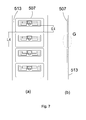
- FIG. 8 A partially enlarged view ( Fig. 8 ) of the products 507 shows a stacked structure of a split antenna RFID tag in the embodiment of Fig. 2 , the stacked structure mainly including an aluminum antenna 501, RFID units 502, a PET film 504 and a surface liner 506, wherein the RFID unit 502s are pasted onto a pair of fold line coupling portions of the aluminum antenna 501, the PET film 504 is pasted onto the RFID unit s502, and the surface liner 506 of a large size is pasted onto the PET film 504.
- the product release liner tape 513 with the products 507 is reeled. When in use, a consumer may tear off the product 507 from the release liner, just like a common tag.
- the all-in-one machine mainly includes: a rack, a main control unit, first, second and third conveying mechanism, etc.
- the first conveying mechanism includes: an unreeling device 101 equipped with a tension regulator 101', a reeling device 109 equipped with a tension regulator 109', a shaft roller set 1 having a rubber roller 12 and a drive shaft 11, a drive shaft 21, a circular antenna die cutter 22 disposed on an upper side of the drive shaft 21, a drive shaft 51, and a circular PET film die cutter 52 disposed on an upper side of the drive shaft 51.
- a guide shaft P1 is provided on a left side of the drive shaft 11, and guide shafts P2, P3 are provided on a right side of the drive shaft 51.
- the second conveying transmission includes an unreeling means 102 and a reeling means 103, for conveying an adhesive tape 510 along with which wasted aluminum foil portions may be discharged.
- the modulus of the circular antenna die cutter 22 depends upon the size of products.
- the die spacing A1 is 3 mm to 5 mm, which facilitates the subsequent asynchronous transferring.
- the die cutter may be designed as a single cutter, double cutters or multiple cutters, depending upon the complexity of shape of antennas and the waste discharge performance.
- the aluminum foil antennas 501 are formed by synchronously cutting in multiple cutter holders under the premise of an equal spacing.
- the aluminum foil 500 on the carrier tape 500' has a thickness ranging from 0.015 mm to 0.050 mm, depending upon the width of products, and is placed on the unreeling device 101 in a reeled manner. The other end of the carrier tape 500' is reeled by the reeling device 109.
- the first conveying mechanism is configured to support and convey the carrier tape 500' adhered with the aluminum foil 500.
- the aluminum foil 500 is die cut by the circular antenna die cutter 22 to form aluminum foil antennas 501 on the carrier tape 500'.
- the wasted aluminum foil portions, beyond the profile of the aluminum foil antennas 501, are pulled out by the reeling means 103 along with the adhesive tape 510.
- the third conveying mechanism includes: a reeling unit 105, a feeding unit 104, a shaft roller set 3 having two rubber rollers 33, 32 and a drive shaft 31, a shaft roller set 4 having two rubber press rollers 43, 42 and a drive shaft 41, and a first flat scraper 8 in front of the shaft roller set 4, the drive shaft 31 and the drive shaft 41 being successively disposed between the drive shaft 21 and the drive shaft 51, the third conveying mechanism being configured to support and convey a base tape 502' carried with several RFID units 502.
- the first flat scraper 8 allows, with the assistance with photoelectric sensors A, B and C, the RFID units to separate from and fall off the release liner tape and then to be pasted onto the corresponding aluminum foil antennas 501 on the carrier tape 500' to form tag modules 503.
- the drive shaft 11, the drive shaft 21, the drive shaft 51, the drive shaft 31 and the drive shaft 41 are equipped with electromagnetic inductors for speed measurement, and each drive shaft is controlled respectively by a motor; and the electromagnetic inductors are each connected to a corresponding input end of the main control unit via an interface circuit, to be monitored, speed regulated and synchronization rectified by the main control unit.
- the main control unit may be PLC or PC.
- the asynchronous labeling of the RFID units 502 is accomplished by the first and third conveying mechanisms and the photoelectric sensors A, B and C (may be optical fiber sensors or CCD image sensors), under the control of the main control unit.
- the initial position of the photoelectric sensors may be adjusted and fixed according to the process requirements, and corresponding parameters are set in software.
- the main control unit receives signals from the photoelectric sensors, and the software makes decision and correspondingly processes to accurately control the motion of the motors.
- the RFID units 502 with back glue are arranged on the base tape 502' in a single row and placed on the feeding unit 104.
- the two rubber press rollers 42, 43 need to be provided thereon with evasion grooves for the IC chip.
- RFID units are separated from the release liner and pasted onto the aluminum foil antennas 501 on the carrier tape 500'; and the base tape 502' is reeled by the reeling unit 105 when passing through the rubber rollers 33, 32.
- the aluminum foil antennas 501 and the RFID units 502 have a different skip distance (or center distance) on the corresponding carrier tape or base tape.
- the skip distance L1 of the aluminum foil antennas 501 is greater than the skip distance L2 of the RFID units 502.
- Fig. 9 is an exploded diagram of asynchronous labeling of RFID units 502.
- the lower part of Fig. 9 is the carrier tape 500' when viewed from the top, and the upper part thereof shows a combined part of the base tape 502' located above the carrier tape 500' and the first flat scraper 8 (referring to Fig. 1 ).
- the carrier tape 500' runs in a horizontal direction
- the base tape 502' runs in a direction towards the right edge of the first flat scrapper 8
- the center lines of the both are in a same vertical plane.
- a position where the lower edge of the RFID units 502 is flush with the right edge of the first flat scrapper 8 is defined as an RFID unit waiting site, and it is detected by the photoelectric sensor B whether the upper edge of the units reaches the RFID unit waiting site.
- a position where the upper edge of the RFID units 502 to be pasted, currently in the RFID unit waiting site, is top-bottom aligned with the upper edge of the aluminum foil antennas 501 to be pasted, is defined as a to-be-pasted antenna site, and it is detected by the photoelectric sensor A whether the lower edge of the aluminum foil antennas 501 to be pasted reaches the to-be-pasted antenna site.
- the photoelectric sensor C identifies information about the position of three or more units in advance, and counts to calculate parameters of the designated units, such as, speed and time of quick motion thereof.
- T2 T1
- T1 T2
- T21 the rapid movement time
- T22 the waiting time
- T3 the pasting time.
- the all-in-one machine further includes a fourth conveying mechanism, the fourth conveying mechanism including an unreeling unit 106, reeling units 107, 108, the circular PET film die cutter 52 and the drive shaft 51, as well as the electromagnetic inductor b.
- the circular PET film die cutter 52 is a circular die cutter manufactured according to the size of the PET protective film 504, with a spacing the same as the size of the die cutter for the aluminum foil antennas 501. The quantity of modules is calculated.
- a combined tape 511' of the release liner and the PET release tape 511 with back glue is placed on the feeding unit 106 which is equipped with a tension controller 125'.
- the reeling unit 107 is configured to reel the release liner.
- the conveying of the combined tape 511' is driven by the drive shaft 51.
- the PET release tape 511 with back glue enters between the drive shaft 51 and the circular PET film die cutter 52, to be cut by the circular PET film die cutter 52 to required PET protective films 504. Meanwhile, the PET protective films 504 are covered on the corresponding tag modules 503 on the carrier tape 500' to form semi-finished products 505.
- the PET, the scraps of which are discharged, is reeled onto the reeling unit 108.
- the all-in-one machine further includes a fifth conveying mechanism and a sixth conveying mechanism, for the secondary asynchronous transferring of the semi-finished products 505 and the synchronous labeling of a surface liner.
- the fifth conveying mechanism includes a shaft roller set 6, a drive shaft 71, a circular die cutter 72 disposed on an upper side of the drive shaft 71, an unreeling unit 121, a reeling unit 125, a guide shaft P4, and a photoelectric sensor F for accurately control the speed of a tape.
- the shaft roller set 6 includes a rubber roller 62 and a drive shaft 61, and an evasion groove, for the radio frequency ICs on the RFID units, is formed on the rubber roller 62.
- a second scrapper 9 is provided between a guide shaft P2 and a guide shaft P3 at an end of the first conveying mechanism.
- the secondary asynchronous transferring process of the semi-finished products 505 is the same as the asynchronous pasting process of the units.
- the semi-finished products 505 on the carrier tape 500' are separated from the carrier tape 500' on the right edge of the scrapper 9 and fall off, due to the change in directions of the P2, the second scrapper 9 and the P3, and are pasted onto the product release liner 513 provided by the feeding unit 121.
- the speed of the product release liner 513 is controlled by a control motor, in order to transfer the semi-finished products 505 and enlarge the spacing therebetween.
- photoelectric sensors D and E (the function of which is the same as the foregoing photoelectric sensors A and B) may be additionally provided to control one of the carrier tape 500' and the product release liner 513 to do the foregoing variable motion.
- the sixth conveying mechanism includes an unreeling unit 122 equipped with a tension regulator 122', reeling units 123, 124, an electromagnetic inductor d, a photoelectrical sensor F, etc.
- the surface liner 512 with back glue on which a pattern required by the customer is continuously printed, is placed on the release liner to form a surface liner roll 512'.
- the surface liner roll 512' is placed on the unreeling unit 122, and by tension control, the original release liner thereof is reeled by the reeling unit 123.
- the surface liner tape 512 with back glue enters the shaft roller set 6 to combine with the product release liner tape 513 with the semi-finished products 505, and is then die cut by the circular die cutter 72 to obtain the products 507.
- the waste is discharged by the reeling unit 124 and the final products 507 are reeled by the reeling unit 125.
- a ratio of the linear velocity of the circular die cutter 72 to the linear velocity of the circular antenna die cutter 22 may be calculated, and this ratio is fed back to the PC or PLC by signals from the electromagnetic inductors d and a for differential compensation.
- Common requirements may be met.
- a photoelectric sensor F is additionally provided, which may work with the foregoing electric eye to give feedback to the main control unit, in order to compensate the accurate alignment between the antenna modules and the surface liner and the precision of die cutting of the surface liner in real time.
Landscapes
- Engineering & Computer Science (AREA)
- Theoretical Computer Science (AREA)
- Computer Hardware Design (AREA)
- Microelectronics & Electronic Packaging (AREA)
- Physics & Mathematics (AREA)
- General Physics & Mathematics (AREA)
- Computer Networks & Wireless Communication (AREA)
- Life Sciences & Earth Sciences (AREA)
- Forests & Forestry (AREA)
- Mechanical Engineering (AREA)
- Textile Engineering (AREA)
- Making Paper Articles (AREA)
- Labeling Devices (AREA)
Applications Claiming Priority (2)
| Application Number | Priority Date | Filing Date | Title |
|---|---|---|---|
| CN201310033460 | 2013-01-29 | ||
| PCT/CN2013/075232 WO2014117448A1 (zh) | 2013-01-29 | 2013-05-07 | 一种分体天线rfid标签的制造方法及设备 |
Publications (3)
| Publication Number | Publication Date |
|---|---|
| EP2953060A1 true EP2953060A1 (de) | 2015-12-09 |
| EP2953060A4 EP2953060A4 (de) | 2017-05-31 |
| EP2953060B1 EP2953060B1 (de) | 2018-10-17 |
Family
ID=49207121
Family Applications (1)
| Application Number | Title | Priority Date | Filing Date |
|---|---|---|---|
| EP13873240.9A Not-in-force EP2953060B1 (de) | 2013-01-29 | 2013-05-07 | Verfahren und vorrichtung zur herstellung von einzelnen antennen-rfid-etiketten |
Country Status (4)
| Country | Link |
|---|---|
| US (1) | US20150363685A1 (de) |
| EP (1) | EP2953060B1 (de) |
| CN (2) | CN203217604U (de) |
| WO (1) | WO2014117448A1 (de) |
Cited By (3)
| Publication number | Priority date | Publication date | Assignee | Title |
|---|---|---|---|---|
| CN109664593A (zh) * | 2019-01-23 | 2019-04-23 | 昆山尚为新材料有限公司 | 一种液态胶印刷到保护膜的模切加工方法 |
| CN112537040A (zh) * | 2020-11-24 | 2021-03-23 | 苏州轩苏原电子材料有限公司 | 一种多层结构产品及其模切工艺 |
| CN112809807A (zh) * | 2020-12-17 | 2021-05-18 | 郑州领胜科技有限公司 | 一次排废冲切成型的方法 |
Families Citing this family (30)
| Publication number | Priority date | Publication date | Assignee | Title |
|---|---|---|---|---|
| CN203217604U (zh) * | 2013-01-29 | 2013-09-25 | 深圳市华阳微电子有限公司 | 制造分体天线rfid标签的一体机 |
| CN104868244B (zh) * | 2015-05-28 | 2018-04-13 | 山东泰宝防伪技术产品有限公司 | Rfid纸基铝天线的生产方法 |
| CN105108827B (zh) * | 2015-09-08 | 2017-02-01 | 苏州达翔新材料有限公司 | 一种异步拖料模切机及模切工艺 |
| CA3013196A1 (en) * | 2016-02-04 | 2017-08-10 | Parker-Hannifin Corporation | Ruggedized radio frequency identification tags |
| CN106003242B (zh) * | 2016-05-16 | 2018-01-09 | 瑞安市丰日机械有限公司 | 异步模切方法及实现该方法的异步模切机 |
| CN106167196B (zh) * | 2016-07-29 | 2017-09-12 | 黄山富田精工制造有限公司 | 一种用于卫生制品生产设备的传送装置 |
| CN105947723B (zh) * | 2016-06-17 | 2017-10-13 | 黄山富田精工制造有限公司 | 一种用于卫生制品生产设备的变间距输送装置 |
| KR102032912B1 (ko) * | 2017-12-19 | 2019-10-16 | (주)파인테크 | 스트레치 필름을 이용한 플렉시블 인쇄회로기판용 필름 절단 장치 |
| JP6941068B2 (ja) * | 2018-02-21 | 2021-09-29 | サトーホールディングス株式会社 | アンテナパターンの製造方法、rfidインレイの製造方法、rfidラベルの製造方法及びrfid媒体の製造方法 |
| CN108556057A (zh) * | 2018-04-01 | 2018-09-21 | 广州橸赛精密机械有限公司 | 一种应用于rfid标签复合模切生产中的增加材料形变能力的方法 |
| CN109702810A (zh) * | 2018-12-25 | 2019-05-03 | 江苏富联通讯技术有限公司 | 一种用于rfid天线制作的模切基材及模切方法 |
| CN110163326A (zh) * | 2019-05-14 | 2019-08-23 | 上海优比科电子科技有限公司 | 金属天线转移装置及方法 |
| CN110288073A (zh) * | 2019-07-10 | 2019-09-27 | 郑致远 | 采用辊压方式连续生产rfid标签天线的工艺 |
| CN110625971B (zh) * | 2019-09-09 | 2025-04-01 | 领胜城科技(江苏)有限公司 | 丝网产品双异步装置及其工艺 |
| CN111185961B (zh) * | 2020-03-18 | 2024-11-29 | 黄光伟 | 复合及多工位全模切超高频标签的天线加工设备和方法 |
| CN111604996A (zh) * | 2020-05-14 | 2020-09-01 | 许世璋 | 模具、模切装置、模切方法、应用 |
| CN113977686B (zh) * | 2020-07-26 | 2023-06-13 | 昊佰电子科技(上海)有限公司 | 一种带铜箔模切件的制备方法 |
| CN112757386A (zh) * | 2020-12-29 | 2021-05-07 | 昆山华冠商标印刷有限公司 | 一种商标加工中的平刀模切框胶排废工艺 |
| CN112974115B (zh) * | 2021-02-04 | 2022-07-12 | 乾大新材料有限公司 | 一种高精度多条背胶涂覆的背胶机 |
| CN112836782B (zh) * | 2021-03-16 | 2025-06-24 | 深圳市骄冠科技实业有限公司 | 一种射频标签及其制造方法 |
| CN112959420B (zh) * | 2021-04-06 | 2025-12-23 | 四川欣富瑞科技发展有限公司 | 一种用于磁性吸波材异步模切装置和工艺 |
| JP7795307B2 (ja) * | 2021-07-26 | 2026-01-07 | リンテック株式会社 | シート供給装置およびシート供給方法 |
| CN113561622B (zh) * | 2021-07-30 | 2023-05-02 | 深圳市伟业鑫精密科技有限公司 | 一种模切复合产品的制备方法及其制备装置 |
| CN113601946B (zh) * | 2021-08-12 | 2024-07-09 | 深圳市领滔科技有限公司 | 带丝网复合片材的模切工艺及带丝网复合片材的模切产线 |
| CN114311141B (zh) * | 2021-12-29 | 2023-09-15 | 金凌印刷(苏州)有限公司 | 一种背胶产品背刀生产装置及其生产工艺 |
| CN114202050A (zh) * | 2022-02-16 | 2022-03-18 | 深圳源明杰科技股份有限公司 | 射频标签及其制作方法 |
| CN115556185B (zh) * | 2022-10-26 | 2025-01-17 | 苏州安洁科技股份有限公司 | 一种长条铝箔胶带平整模切工艺 |
| CN117260883B (zh) * | 2023-08-23 | 2025-12-19 | 深圳市领略数控设备有限公司 | 模切方法及模切设备 |
| CN120156933B (zh) * | 2023-12-08 | 2025-11-21 | 上海昊佰智造精密电子股份有限公司 | 一种pi产品省料模切装置 |
| CN118493519A (zh) * | 2024-05-21 | 2024-08-16 | 苏州安洁科技股份有限公司 | 一种异步冲切工艺 |
Family Cites Families (5)
| Publication number | Priority date | Publication date | Assignee | Title |
|---|---|---|---|---|
| US7119685B2 (en) * | 2004-02-23 | 2006-10-10 | Checkpoint Systems, Inc. | Method for aligning capacitor plates in a security tag and a capacitor formed thereby |
| US20080289753A1 (en) * | 2007-05-23 | 2008-11-27 | Bauer Richard K | Method of making composite webs of record members and record members made thereby |
| CN101609926A (zh) * | 2008-06-17 | 2009-12-23 | 深圳市华阳微电子有限公司 | 采用分体天线的超高频电子标签及其制造方法 |
| CN101844421B (zh) * | 2010-05-14 | 2012-09-05 | 苏州工业园区宝优际通讯科技有限公司 | 一种标签加工装置及标签制作工艺 |
| CN203217604U (zh) * | 2013-01-29 | 2013-09-25 | 深圳市华阳微电子有限公司 | 制造分体天线rfid标签的一体机 |
-
2013
- 2013-03-14 CN CN2013201160649U patent/CN203217604U/zh not_active Withdrawn - After Issue
- 2013-03-14 CN CN201310081209.0A patent/CN103971151B/zh not_active Expired - Fee Related
- 2013-05-07 US US14/764,158 patent/US20150363685A1/en not_active Abandoned
- 2013-05-07 EP EP13873240.9A patent/EP2953060B1/de not_active Not-in-force
- 2013-05-07 WO PCT/CN2013/075232 patent/WO2014117448A1/zh not_active Ceased
Non-Patent Citations (1)
| Title |
|---|
| See references of WO2014117448A1 * |
Cited By (3)
| Publication number | Priority date | Publication date | Assignee | Title |
|---|---|---|---|---|
| CN109664593A (zh) * | 2019-01-23 | 2019-04-23 | 昆山尚为新材料有限公司 | 一种液态胶印刷到保护膜的模切加工方法 |
| CN112537040A (zh) * | 2020-11-24 | 2021-03-23 | 苏州轩苏原电子材料有限公司 | 一种多层结构产品及其模切工艺 |
| CN112809807A (zh) * | 2020-12-17 | 2021-05-18 | 郑州领胜科技有限公司 | 一次排废冲切成型的方法 |
Also Published As
| Publication number | Publication date |
|---|---|
| EP2953060A4 (de) | 2017-05-31 |
| US20150363685A1 (en) | 2015-12-17 |
| EP2953060B1 (de) | 2018-10-17 |
| CN103971151A (zh) | 2014-08-06 |
| CN203217604U (zh) | 2013-09-25 |
| WO2014117448A1 (zh) | 2014-08-07 |
| CN103971151B (zh) | 2017-05-31 |
Similar Documents
| Publication | Publication Date | Title |
|---|---|---|
| EP2953060B1 (de) | Verfahren und vorrichtung zur herstellung von einzelnen antennen-rfid-etiketten | |
| US20080022866A1 (en) | Sheet punching and embossing machine with register orienting and method for operating a sheet punching and embossing machine | |
| CA1243417A (en) | Printed circuit board laminating apparatus | |
| CN206363038U (zh) | 连续异步转贴设备 | |
| CN106671551A (zh) | 一种多层结构柔性电子连续复合系统 | |
| CN104441783B (zh) | 具有配合冲制带的用于冲制标签的设备 | |
| CN106276382A (zh) | 胶膜送料机构 | |
| KR20170006847A (ko) | 내부에 공간부가 형성된 로터리식 필름 제조 방법 | |
| US20100038430A1 (en) | Large-unitized inlet manufacturing method, inlet adhesive tape, its manufacturing method, and its manufacturing device | |
| CN211349403U (zh) | 一种复合及多工位全模切超高频的天线加工设备 | |
| CN220720569U (zh) | 一种rfid平张纸电子标签复合机 | |
| CN102582211B (zh) | 印刷贴合生产线及其模冲切设备 | |
| WO2007000407A2 (de) | Verfahren und vorrichtung zur herstellung von selbstklebenden rfid-transpondern | |
| CN214724858U (zh) | 带跳步控制系统的十字走料式贴合机 | |
| US20220194070A1 (en) | Sheet processing system and method | |
| CN222891369U (zh) | 设置有模切组件的遮胶设备 | |
| CN107298199B (zh) | 一种同步多规格钢板覆膜机及留边覆膜钢板加工方法 | |
| CN206394186U (zh) | 一种多层结构柔性电子连续复合系统 | |
| CN109760368B (zh) | 新型高速全自动压边制袋机 | |
| CN119427909B (zh) | 一种印刷产品异步胶条无缝拼接工艺 | |
| CN111275155A (zh) | 一种复合及多工位全模切超高频的天线加工设备和方法 | |
| CN214727207U (zh) | 钢网贴合热压生产线 | |
| KR102674656B1 (ko) | 커팅 유닛 일체형 합지 장치 | |
| CN222712319U (zh) | 一种高效不干胶标签排废机构 | |
| CN210526051U (zh) | 一种斜进式电化铝烫印装置 |
Legal Events
| Date | Code | Title | Description |
|---|---|---|---|
| PUAI | Public reference made under article 153(3) epc to a published international application that has entered the european phase |
Free format text: ORIGINAL CODE: 0009012 |
|
| 17P | Request for examination filed |
Effective date: 20150828 |
|
| AK | Designated contracting states |
Kind code of ref document: A1 Designated state(s): AL AT BE BG CH CY CZ DE DK EE ES FI FR GB GR HR HU IE IS IT LI LT LU LV MC MK MT NL NO PL PT RO RS SE SI SK SM TR |
|
| AX | Request for extension of the european patent |
Extension state: BA ME |
|
| DAX | Request for extension of the european patent (deleted) | ||
| STAA | Information on the status of an ep patent application or granted ep patent |
Free format text: STATUS: REQUEST FOR EXAMINATION WAS MADE |
|
| REG | Reference to a national code |
Ref country code: DE Ref legal event code: R079 Ref document number: 602013045393 Country of ref document: DE Free format text: PREVIOUS MAIN CLASS: G06K0019070000 Ipc: G06K0019077000 |
|
| A4 | Supplementary search report drawn up and despatched |
Effective date: 20170504 |
|
| RIC1 | Information provided on ipc code assigned before grant |
Ipc: H01Q 1/22 20060101ALI20170427BHEP Ipc: B65H 37/00 20060101ALI20170427BHEP Ipc: B65H 37/04 20060101ALI20170427BHEP Ipc: G06K 19/077 20060101AFI20170427BHEP Ipc: G06K 19/07 20060101ALI20170427BHEP Ipc: H01Q 23/00 20060101ALI20170427BHEP Ipc: B26F 1/38 20060101ALI20170427BHEP |
|
| GRAP | Despatch of communication of intention to grant a patent |
Free format text: ORIGINAL CODE: EPIDOSNIGR1 |
|
| STAA | Information on the status of an ep patent application or granted ep patent |
Free format text: STATUS: GRANT OF PATENT IS INTENDED |
|
| INTG | Intention to grant announced |
Effective date: 20180425 |
|
| GRAJ | Information related to disapproval of communication of intention to grant by the applicant or resumption of examination proceedings by the epo deleted |
Free format text: ORIGINAL CODE: EPIDOSDIGR1 |
|
| STAA | Information on the status of an ep patent application or granted ep patent |
Free format text: STATUS: REQUEST FOR EXAMINATION WAS MADE |
|
| GRAR | Information related to intention to grant a patent recorded |
Free format text: ORIGINAL CODE: EPIDOSNIGR71 |
|
| GRAS | Grant fee paid |
Free format text: ORIGINAL CODE: EPIDOSNIGR3 |
|
| STAA | Information on the status of an ep patent application or granted ep patent |
Free format text: STATUS: GRANT OF PATENT IS INTENDED |
|
| GRAA | (expected) grant |
Free format text: ORIGINAL CODE: 0009210 |
|
| STAA | Information on the status of an ep patent application or granted ep patent |
Free format text: STATUS: THE PATENT HAS BEEN GRANTED |
|
| INTC | Intention to grant announced (deleted) | ||
| AK | Designated contracting states |
Kind code of ref document: B1 Designated state(s): AL AT BE BG CH CY CZ DE DK EE ES FI FR GB GR HR HU IE IS IT LI LT LU LV MC MK MT NL NO PL PT RO RS SE SI SK SM TR |
|
| INTG | Intention to grant announced |
Effective date: 20180907 |
|
| REG | Reference to a national code |
Ref country code: GB Ref legal event code: FG4D |
|
| REG | Reference to a national code |
Ref country code: CH Ref legal event code: EP |
|
| REG | Reference to a national code |
Ref country code: IE Ref legal event code: FG4D |
|
| REG | Reference to a national code |
Ref country code: DE Ref legal event code: R096 Ref document number: 602013045393 Country of ref document: DE Ref country code: AT Ref legal event code: REF Ref document number: 1054856 Country of ref document: AT Kind code of ref document: T Effective date: 20181115 |
|
| REG | Reference to a national code |
Ref country code: NL Ref legal event code: MP Effective date: 20181017 |
|
| REG | Reference to a national code |
Ref country code: LT Ref legal event code: MG4D |
|
| REG | Reference to a national code |
Ref country code: AT Ref legal event code: MK05 Ref document number: 1054856 Country of ref document: AT Kind code of ref document: T Effective date: 20181017 |
|
| PG25 | Lapsed in a contracting state [announced via postgrant information from national office to epo] |
Ref country code: NL Free format text: LAPSE BECAUSE OF FAILURE TO SUBMIT A TRANSLATION OF THE DESCRIPTION OR TO PAY THE FEE WITHIN THE PRESCRIBED TIME-LIMIT Effective date: 20181017 |
|
| PG25 | Lapsed in a contracting state [announced via postgrant information from national office to epo] |
Ref country code: BG Free format text: LAPSE BECAUSE OF FAILURE TO SUBMIT A TRANSLATION OF THE DESCRIPTION OR TO PAY THE FEE WITHIN THE PRESCRIBED TIME-LIMIT Effective date: 20190117 Ref country code: NO Free format text: LAPSE BECAUSE OF FAILURE TO SUBMIT A TRANSLATION OF THE DESCRIPTION OR TO PAY THE FEE WITHIN THE PRESCRIBED TIME-LIMIT Effective date: 20190117 Ref country code: FI Free format text: LAPSE BECAUSE OF FAILURE TO SUBMIT A TRANSLATION OF THE DESCRIPTION OR TO PAY THE FEE WITHIN THE PRESCRIBED TIME-LIMIT Effective date: 20181017 Ref country code: IS Free format text: LAPSE BECAUSE OF FAILURE TO SUBMIT A TRANSLATION OF THE DESCRIPTION OR TO PAY THE FEE WITHIN THE PRESCRIBED TIME-LIMIT Effective date: 20190217 Ref country code: LT Free format text: LAPSE BECAUSE OF FAILURE TO SUBMIT A TRANSLATION OF THE DESCRIPTION OR TO PAY THE FEE WITHIN THE PRESCRIBED TIME-LIMIT Effective date: 20181017 Ref country code: LV Free format text: LAPSE BECAUSE OF FAILURE TO SUBMIT A TRANSLATION OF THE DESCRIPTION OR TO PAY THE FEE WITHIN THE PRESCRIBED TIME-LIMIT Effective date: 20181017 Ref country code: PL Free format text: LAPSE BECAUSE OF FAILURE TO SUBMIT A TRANSLATION OF THE DESCRIPTION OR TO PAY THE FEE WITHIN THE PRESCRIBED TIME-LIMIT Effective date: 20181017 Ref country code: HR Free format text: LAPSE BECAUSE OF FAILURE TO SUBMIT A TRANSLATION OF THE DESCRIPTION OR TO PAY THE FEE WITHIN THE PRESCRIBED TIME-LIMIT Effective date: 20181017 Ref country code: ES Free format text: LAPSE BECAUSE OF FAILURE TO SUBMIT A TRANSLATION OF THE DESCRIPTION OR TO PAY THE FEE WITHIN THE PRESCRIBED TIME-LIMIT Effective date: 20181017 Ref country code: AT Free format text: LAPSE BECAUSE OF FAILURE TO SUBMIT A TRANSLATION OF THE DESCRIPTION OR TO PAY THE FEE WITHIN THE PRESCRIBED TIME-LIMIT Effective date: 20181017 |
|
| PG25 | Lapsed in a contracting state [announced via postgrant information from national office to epo] |
Ref country code: PT Free format text: LAPSE BECAUSE OF FAILURE TO SUBMIT A TRANSLATION OF THE DESCRIPTION OR TO PAY THE FEE WITHIN THE PRESCRIBED TIME-LIMIT Effective date: 20190217 Ref country code: GR Free format text: LAPSE BECAUSE OF FAILURE TO SUBMIT A TRANSLATION OF THE DESCRIPTION OR TO PAY THE FEE WITHIN THE PRESCRIBED TIME-LIMIT Effective date: 20190118 Ref country code: SE Free format text: LAPSE BECAUSE OF FAILURE TO SUBMIT A TRANSLATION OF THE DESCRIPTION OR TO PAY THE FEE WITHIN THE PRESCRIBED TIME-LIMIT Effective date: 20181017 Ref country code: RS Free format text: LAPSE BECAUSE OF FAILURE TO SUBMIT A TRANSLATION OF THE DESCRIPTION OR TO PAY THE FEE WITHIN THE PRESCRIBED TIME-LIMIT Effective date: 20181017 Ref country code: AL Free format text: LAPSE BECAUSE OF FAILURE TO SUBMIT A TRANSLATION OF THE DESCRIPTION OR TO PAY THE FEE WITHIN THE PRESCRIBED TIME-LIMIT Effective date: 20181017 |
|
| REG | Reference to a national code |
Ref country code: DE Ref legal event code: R097 Ref document number: 602013045393 Country of ref document: DE |
|
| PG25 | Lapsed in a contracting state [announced via postgrant information from national office to epo] |
Ref country code: DK Free format text: LAPSE BECAUSE OF FAILURE TO SUBMIT A TRANSLATION OF THE DESCRIPTION OR TO PAY THE FEE WITHIN THE PRESCRIBED TIME-LIMIT Effective date: 20181017 Ref country code: IT Free format text: LAPSE BECAUSE OF FAILURE TO SUBMIT A TRANSLATION OF THE DESCRIPTION OR TO PAY THE FEE WITHIN THE PRESCRIBED TIME-LIMIT Effective date: 20181017 Ref country code: CZ Free format text: LAPSE BECAUSE OF FAILURE TO SUBMIT A TRANSLATION OF THE DESCRIPTION OR TO PAY THE FEE WITHIN THE PRESCRIBED TIME-LIMIT Effective date: 20181017 |
|
| PGFP | Annual fee paid to national office [announced via postgrant information from national office to epo] |
Ref country code: DE Payment date: 20190527 Year of fee payment: 7 |
|
| PLBE | No opposition filed within time limit |
Free format text: ORIGINAL CODE: 0009261 |
|
| STAA | Information on the status of an ep patent application or granted ep patent |
Free format text: STATUS: NO OPPOSITION FILED WITHIN TIME LIMIT |
|
| PG25 | Lapsed in a contracting state [announced via postgrant information from national office to epo] |
Ref country code: SK Free format text: LAPSE BECAUSE OF FAILURE TO SUBMIT A TRANSLATION OF THE DESCRIPTION OR TO PAY THE FEE WITHIN THE PRESCRIBED TIME-LIMIT Effective date: 20181017 Ref country code: RO Free format text: LAPSE BECAUSE OF FAILURE TO SUBMIT A TRANSLATION OF THE DESCRIPTION OR TO PAY THE FEE WITHIN THE PRESCRIBED TIME-LIMIT Effective date: 20181017 Ref country code: SM Free format text: LAPSE BECAUSE OF FAILURE TO SUBMIT A TRANSLATION OF THE DESCRIPTION OR TO PAY THE FEE WITHIN THE PRESCRIBED TIME-LIMIT Effective date: 20181017 Ref country code: EE Free format text: LAPSE BECAUSE OF FAILURE TO SUBMIT A TRANSLATION OF THE DESCRIPTION OR TO PAY THE FEE WITHIN THE PRESCRIBED TIME-LIMIT Effective date: 20181017 |
|
| PGFP | Annual fee paid to national office [announced via postgrant information from national office to epo] |
Ref country code: FR Payment date: 20190527 Year of fee payment: 7 |
|
| 26N | No opposition filed |
Effective date: 20190718 |
|
| PG25 | Lapsed in a contracting state [announced via postgrant information from national office to epo] |
Ref country code: SI Free format text: LAPSE BECAUSE OF FAILURE TO SUBMIT A TRANSLATION OF THE DESCRIPTION OR TO PAY THE FEE WITHIN THE PRESCRIBED TIME-LIMIT Effective date: 20181017 |
|
| PGFP | Annual fee paid to national office [announced via postgrant information from national office to epo] |
Ref country code: GB Payment date: 20190527 Year of fee payment: 7 |
|
| REG | Reference to a national code |
Ref country code: CH Ref legal event code: PL |
|
| PG25 | Lapsed in a contracting state [announced via postgrant information from national office to epo] |
Ref country code: MC Free format text: LAPSE BECAUSE OF FAILURE TO SUBMIT A TRANSLATION OF THE DESCRIPTION OR TO PAY THE FEE WITHIN THE PRESCRIBED TIME-LIMIT Effective date: 20181017 Ref country code: CH Free format text: LAPSE BECAUSE OF NON-PAYMENT OF DUE FEES Effective date: 20190531 Ref country code: LI Free format text: LAPSE BECAUSE OF NON-PAYMENT OF DUE FEES Effective date: 20190531 |
|
| REG | Reference to a national code |
Ref country code: BE Ref legal event code: MM Effective date: 20190531 |
|
| PG25 | Lapsed in a contracting state [announced via postgrant information from national office to epo] |
Ref country code: LU Free format text: LAPSE BECAUSE OF NON-PAYMENT OF DUE FEES Effective date: 20190507 |
|
| PG25 | Lapsed in a contracting state [announced via postgrant information from national office to epo] |
Ref country code: TR Free format text: LAPSE BECAUSE OF FAILURE TO SUBMIT A TRANSLATION OF THE DESCRIPTION OR TO PAY THE FEE WITHIN THE PRESCRIBED TIME-LIMIT Effective date: 20181017 |
|
| PG25 | Lapsed in a contracting state [announced via postgrant information from national office to epo] |
Ref country code: IE Free format text: LAPSE BECAUSE OF NON-PAYMENT OF DUE FEES Effective date: 20190507 |
|
| PG25 | Lapsed in a contracting state [announced via postgrant information from national office to epo] |
Ref country code: BE Free format text: LAPSE BECAUSE OF NON-PAYMENT OF DUE FEES Effective date: 20190531 |
|
| REG | Reference to a national code |
Ref country code: DE Ref legal event code: R119 Ref document number: 602013045393 Country of ref document: DE |
|
| GBPC | Gb: european patent ceased through non-payment of renewal fee |
Effective date: 20200507 |
|
| PG25 | Lapsed in a contracting state [announced via postgrant information from national office to epo] |
Ref country code: GB Free format text: LAPSE BECAUSE OF NON-PAYMENT OF DUE FEES Effective date: 20200507 Ref country code: FR Free format text: LAPSE BECAUSE OF NON-PAYMENT OF DUE FEES Effective date: 20200531 |
|
| PG25 | Lapsed in a contracting state [announced via postgrant information from national office to epo] |
Ref country code: CY Free format text: LAPSE BECAUSE OF FAILURE TO SUBMIT A TRANSLATION OF THE DESCRIPTION OR TO PAY THE FEE WITHIN THE PRESCRIBED TIME-LIMIT Effective date: 20181017 Ref country code: DE Free format text: LAPSE BECAUSE OF NON-PAYMENT OF DUE FEES Effective date: 20201201 |
|
| PG25 | Lapsed in a contracting state [announced via postgrant information from national office to epo] |
Ref country code: MT Free format text: LAPSE BECAUSE OF FAILURE TO SUBMIT A TRANSLATION OF THE DESCRIPTION OR TO PAY THE FEE WITHIN THE PRESCRIBED TIME-LIMIT Effective date: 20181017 Ref country code: HU Free format text: LAPSE BECAUSE OF FAILURE TO SUBMIT A TRANSLATION OF THE DESCRIPTION OR TO PAY THE FEE WITHIN THE PRESCRIBED TIME-LIMIT; INVALID AB INITIO Effective date: 20130507 |
|
| PG25 | Lapsed in a contracting state [announced via postgrant information from national office to epo] |
Ref country code: MK Free format text: LAPSE BECAUSE OF FAILURE TO SUBMIT A TRANSLATION OF THE DESCRIPTION OR TO PAY THE FEE WITHIN THE PRESCRIBED TIME-LIMIT Effective date: 20181017 |