EP2953147A1 - Dispositif d'émission de puissance sans contact - Google Patents
Dispositif d'émission de puissance sans contact Download PDFInfo
- Publication number
- EP2953147A1 EP2953147A1 EP14746579.3A EP14746579A EP2953147A1 EP 2953147 A1 EP2953147 A1 EP 2953147A1 EP 14746579 A EP14746579 A EP 14746579A EP 2953147 A1 EP2953147 A1 EP 2953147A1
- Authority
- EP
- European Patent Office
- Prior art keywords
- coil
- power
- core
- coils
- power transmitting
- Prior art date
- Legal status (The legal status is an assumption and is not a legal conclusion. Google has not performed a legal analysis and makes no representation as to the accuracy of the status listed.)
- Withdrawn
Links
Images



Classifications
-
- H—ELECTRICITY
- H01—ELECTRIC ELEMENTS
- H01F—MAGNETS; INDUCTANCES; TRANSFORMERS; SELECTION OF MATERIALS FOR THEIR MAGNETIC PROPERTIES
- H01F27/00—Details of transformers or inductances, in general
- H01F27/28—Coils; Windings; Conductive connections
- H01F27/2823—Wires
-
- H—ELECTRICITY
- H01—ELECTRIC ELEMENTS
- H01F—MAGNETS; INDUCTANCES; TRANSFORMERS; SELECTION OF MATERIALS FOR THEIR MAGNETIC PROPERTIES
- H01F27/00—Details of transformers or inductances, in general
- H01F27/34—Special means for preventing or reducing unwanted electric or magnetic effects, e.g. no-load losses, reactive currents, harmonics, oscillations, leakage fields
- H01F27/38—Auxiliary core members; Auxiliary coils or windings
-
- H—ELECTRICITY
- H01—ELECTRIC ELEMENTS
- H01F—MAGNETS; INDUCTANCES; TRANSFORMERS; SELECTION OF MATERIALS FOR THEIR MAGNETIC PROPERTIES
- H01F38/00—Adaptations of transformers or inductances for specific applications or functions
- H01F38/14—Inductive couplings
-
- H—ELECTRICITY
- H01—ELECTRIC ELEMENTS
- H01F—MAGNETS; INDUCTANCES; TRANSFORMERS; SELECTION OF MATERIALS FOR THEIR MAGNETIC PROPERTIES
- H01F5/00—Coils
- H01F5/02—Coils wound on non-magnetic supports, e.g. formers
-
- H—ELECTRICITY
- H02—GENERATION; CONVERSION OR DISTRIBUTION OF ELECTRIC POWER
- H02J—ELECTRIC POWER NETWORKS; CIRCUIT ARRANGEMENTS OR SYSTEMS FOR SUPPLYING OR DISTRIBUTING ELECTRIC POWER; SYSTEMS FOR STORING ELECTRIC ENERGY
- H02J50/00—Circuit arrangements or systems for wireless supply or distribution of electric power
- H02J50/10—Circuit arrangements or systems for wireless supply or distribution of electric power using inductive coupling
-
- H—ELECTRICITY
- H02—GENERATION; CONVERSION OR DISTRIBUTION OF ELECTRIC POWER
- H02J—ELECTRIC POWER NETWORKS; CIRCUIT ARRANGEMENTS OR SYSTEMS FOR SUPPLYING OR DISTRIBUTING ELECTRIC POWER; SYSTEMS FOR STORING ELECTRIC ENERGY
- H02J50/00—Circuit arrangements or systems for wireless supply or distribution of electric power
- H02J50/70—Circuit arrangements or systems for wireless supply or distribution of electric power involving the reduction of electric, magnetic or electromagnetic leakage fields
Definitions
- the present invention relates to non-contact power transmission systems for charging, for example, electric propulsion vehicles such as electric vehicles and plug-in hybrid vehicles.
- PATENT DOCUMENT 1 discloses a conventional power transmitting coil or power receiving coil for a non-contact power transmission system.
- the coil includes a plurality of cores arranged at some intervals.
- the plurality of cores output lines of magnetic force filling gaps between themselves.
- those cores together function as a single core with an enlarged size, because the overall size of the core includes the sizes of the gaps. This feature allows for addressing the issue of misalignment between the power transmitting and receiving coils and reducing the sizes and weights of the coils.
- PATENT DOCUMENT 2 discloses a power transmitting coil or power receiving coil including an H-shaped core having a narrowed portion wound with a coil.
- the spatial magnetic flux distribution between the power transmitting and receiving coils is determined by the shape of a portion of the core not wound with any coil.
- magnetomotive force of the coil does not change.
- such a narrowed portion reduces the size and weight of the power transmitting coil or the power receiving coil.
- PATENT DOCUMENT 3 discloses a power transmitting coil and a power receiving coil including an H-shaped core. A portion of the core not wound with any coil is disposed closer to the other core than another portion of the former core wound with the coil is. This reduces the distance between respective portions of the core not wound with any coil, thereby increasing the coefficient of coupling between the coils to improve power supply efficiency.
- the magnetic flux concentrates along the winding axis of the coil.
- the winding axis of the coil is horizontally placed, the strength of a leakage magnetic field into the environment increases.
- an intense magnetic flux diffuses to the vicinity of an end of the core, thereby causing the problem of an even stronger leakage magnetic field into the environment.
- the present invention addresses this conventional problem. It is an objective of the present invention to provide a non-contact power transmission system which reduces a leakage magnetic flux into the environment, even if the winding axis of a coil is placed horizontally.
- a non-contact power transmission system includes a power transmitting coil, and a power receiving coil facing the power transmitting coil, and transmits electric power from the power transmitting coil to the power receiving coil via a non-contact method by utilizing electromagnetic induction.
- At least one of the power transmitting and receiving coils includes a first coil in which a wire is wound around a first core, and a second coil in which a wire is around a second core.
- the second coil is placed at at least one end of a winding axis of the first coil.
- a winding axis of the second coil is inclined with respect to the winding axis of the first coil toward the power transmitting or receiving coil that faces the second coil.
- most of the magnetic flux diffusing horizontally from the end of the first coil i.e., along the winding axis of the first coil
- the second coil upward (i.e., toward the power transmitting/receiving coil that faces the second coil), thereby reducing a leakage magnetic flux into the environment.
- the second coil orients most of the magnetic flux diffusing from the end of the first coil toward the power transmitting/receiving coil that faces the second coil, thereby reducing a leakage magnetic field into the environment.
- FIG. 1 is a block diagram of a non-contact power transmission system according to an embodiment of the present invention.
- FIG. 2 illustrates the appearance of the non-contact power transmission system when a vehicle is parked in a parking space.
- the non-contact power transmission system includes, for example, a power supplier 2 in a parking space, and a power receiver 4 mounted on an electric propulsion vehicle.
- the power supplier 2 includes a power unit 8, an inverter section 10, a ground-side coil unit (i.e., a power transmitting coil) 12, and a supplier-side controller (e.g., a microcomputer) 16.
- the power unit 8 is connected to a commercial power supply 6.
- the supplier-side controller 16 functions as a power control section 17.
- the power receiver 4 includes a vehicle-side coil unit (i.e., a power receiving coil) 18, a rectifier 20, a battery 22 as a load, and a receiver-side controller (e.g., a microcomputer) 24.
- the commercial power supply 6 is a low-frequency AC power supply of 200 V, and connected to the input terminal of the power unit 8.
- the output terminal of the power unit 8 is connected to the input terminal of the inverter section 10.
- the output terminal of the inverter section 10 is connected to the ground-side coil unit 12.
- the output terminal of the vehicle-side coil unit 18 is connected to the input terminal of the rectifier 20.
- the output terminal of the rectifier 20 is connected to the battery 22.
- the ground-side coil unit 12 is placed on the ground.
- the power unit 8 is set upright, for example, at a predetermined distance from the ground-side coil unit 12.
- the vehicle-side coil unit 18 is attached to, for example, the bottom of the vehicle (e.g., a chassis).
- the supplier-side controller 16 communicates with the receiver-side controller 24.
- the receiver-side controller 24 determines a power command value in accordance with a detected residual voltage of the battery 22, and sends the determined power command value to the supplier-side controller 16.
- the supplier-side controller 16 compares the power to be supplied detected by the ground-side coil unit 12 with the received power command value, and drives the inverter section 10 so as to obtain the power command value.
- the vehicle-side coil unit 18 may be arranged to face the ground-side coil unit 12 by moving the vehicle as appropriate.
- the supplier-side controller 16 controls the inverter section 10 being driven to generate an RF electromagnetic field between the ground-side coil unit 12 and the vehicle-side coil unit 18.
- the power receiver 4 extracts electric power from the RF electromagnetic field to charge the battery 22 with the extracted electric power.
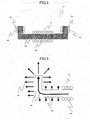
- FIG. 3 is a cross-sectional view of the ground-side coil unit (i.e., the power transmitting coil) 12 in the non-contact power transmission system according to an embodiment of the present invention.
- the vehicle-side coil unit (i.e., the power receiving coil) 18 may have a similar configuration.
- the ground-side coil unit 12 includes a first coil 31 and second coils 32.
- the first coil 31 is comprised of a (first) core 33 made of a magnetic material such as ferrite, and a wire 30 wound around the core 33.
- Each of the second coils 32 is formed at an associated end of the first coil 31 by winding a wire 30 around a (second) core 33.
- the winding axis of the first coil 31 is placed horizontally.
- the winding axes of the second coils 32 are placed vertically.
- the cores 33 of the first and second coils 31 and 32 are formed continuously. Generated magnetic fluxes interlink with the respective coils.
- An output from the inverter section 10 is transmitted to the wires 30 of the first and second coils 31 and 32 to generate a magnetic flux.
- the generated magnetic flux is transmitted through the core 33 and creates magnetic paths going mainly upward (i.e., toward the vehicle-side coil unit 18 that faces the coils) from the end of the second coils 32.
- the magnetic paths generate an RF electromagnetic field between the ground-side coil unit 12 and the vehicle-side coil unit 18 located above to transmit electric power.
- FIG. 4 is a sectional side view of a comparison example illustrating magnetic flux vectors generated when no second coil 32 is provided.
- the magnetic flux 40 in the core 33 which has been generated by the wire 30, propagates through the core 33 toward the end of the core 33.
- the same magnetic flux density as in the magnetic body cannot be maintained.
- the magnetic flux diffuses from the winding end of the wire 30 to the vicinity of an end of the core 33 in a direction in which the magnetic flux density decreases (e.g., the direction perpendicular to the surface of the core).
- a leakage magnetic flux 41 particularly significantly increases along the winding axis of the first coil 31 (i.e., in the horizontal direction).
- FIG. 5 illustrates magnetic flux vectors generated in this embodiment.
- the magnetic flux 40 in the core 33 which has been generated by the wire 30 of the first coil 31, goes upward via the core 33 and the second coils 32.
- the second coils 32 of which wires 30 are wound in the same direction as that of the first coil 31 much of the magnetic flux 40 is attracted toward the second coils 32.
- the magnetic flux 40 is transmitted through the core 33 to the vicinity of the ends of the second coils 32 with a reduced leakage magnetic flux.
- the leakage magnetic flux 41 along the winding axis of the first coil 31 (in the horizontal direction) is reduced as compared to the comparison example.
- the power transmitting coil 12 faces the power receiving coil 18.
- the non-contact power transmission system transmits electric power from the power transmitting coil 12 to the power receiving coil 18 via a non-contact method by utilizing electromagnetic induction.
- At least one of the power transmitting coil 12 and the power receiving coil 18 includes the first coil 31 formed by winding the wire 30 around the first core, and the second coils 32, each of which is placed at an associated end of the winding axis of the first coil 31 and formed by winding the wire 30 around the second core.
- the winding axis of each second coil 32 is inclined, with respect to the winding axis of the first coil 31, perpendicularly to the power transmitting or receiving coil 12 or 18 that faces the second coil 32.
- FIG. 6 is a partial cross-sectional view of a power transmitting coil (or a power receiving coil) according to a first variation of the present invention.
- the core 33 of the first coil 31 is spaced apart from the core 33 of each second coil 32. If there is a space between the cores 33, the magnetic flux 40 diffuses once at the end of the core 33 of the first coil 31, and then enters the core 33 of the second coil 32. This reduces the magnetic flux diffusing through the core 33 of the second coil 32, thereby further reducing the leakage magnetic flux along the winding axis of the first coil 31 (in the horizontal direction).
- FIG. 7 and FIG. 8 are partial cross-sectional views of a power transmitting coil (or a power receiving coil) according to a second variation of the present invention.
- each second coil 32 is inclined with respect to the vertical direction.
- the magnetic flux from the end of the second coil 32 is provided in such a direction that broadens the range of the magnetic flux coming from the end of the second coil 32 as compared to the vertical direction, thereby forming a wide RF electromagnetic field. Accordingly, a leakage magnetic flux decreases, and in addition, deterioration in power transmission efficiency caused by misalignment of a vehicle is also reducible.
- the wires 30 of the first and second coils 31 and 32 are wound in the same direction and connected in series.
- any other configuration provides similar advantages.
- the wires 30 of the first and second coils 31 and 32 may be wound in opposite directions, and the ends of the wire 30 of the first coil 31 may be connected to the wires 30 of the second coils 32 in reverse directions to allow a current to flow in the reverse directions.
- the magnetic fields of the second coils 32 are generated in the direction in which the magnetic flux 40 generated by the first coil 31 increases.
- this embodiment also provides the advantage of reducing a leakage magnetic flux along the winding axis of the first coil 31 (in the horizontal direction).
- the ground-side coil unit 12 includes the first and second coils 31 and 32.
- the present invention is not limited thereto.
- the vehicle-side coil unit 18 of the power receiver 4 may include the first and second coils 31 and 32.
- each of the ground-side coil unit 12 of the power supplier 2 and the vehicle-side coil unit 18 of the power receiver 4 may include the first and second coils 31 and 32.
- the second coils 32 are provided on the right and left sides of the first coil 31, a second coil 32 may be provided only on one side.
- the core may also be formed in any other shape such as a cylindrical shape.
- a plate made of a non-magnetic material such as aluminum may be disposed around the ground-side coil unit 12 and the vehicle-side coil unit 18 to further reduce the leakage magnetic flux.
- a non-contact power transmission system is useful as, for example, a power receiver and a power supplier of an electric propulsion vehicle, which may be incautiously accessed by a human or an object.
Landscapes
- Engineering & Computer Science (AREA)
- Power Engineering (AREA)
- Computer Networks & Wireless Communication (AREA)
- Physics & Mathematics (AREA)
- Electromagnetism (AREA)
- Charge And Discharge Circuits For Batteries Or The Like (AREA)
- Electric Propulsion And Braking For Vehicles (AREA)
- Coils Of Transformers For General Uses (AREA)
Applications Claiming Priority (2)
| Application Number | Priority Date | Filing Date | Title |
|---|---|---|---|
| JP2013015070 | 2013-01-30 | ||
| PCT/JP2014/000444 WO2014119297A1 (fr) | 2013-01-30 | 2014-01-29 | Dispositif d'émission de puissance sans contact |
Publications (2)
| Publication Number | Publication Date |
|---|---|
| EP2953147A1 true EP2953147A1 (fr) | 2015-12-09 |
| EP2953147A4 EP2953147A4 (fr) | 2016-04-06 |
Family
ID=51262015
Family Applications (1)
| Application Number | Title | Priority Date | Filing Date |
|---|---|---|---|
| EP14746579.3A Withdrawn EP2953147A4 (fr) | 2013-01-30 | 2014-01-29 | Dispositif d'émission de puissance sans contact |
Country Status (4)
| Country | Link |
|---|---|
| US (1) | US20150332847A1 (fr) |
| EP (1) | EP2953147A4 (fr) |
| JP (1) | JP6300107B2 (fr) |
| WO (1) | WO2014119297A1 (fr) |
Cited By (1)
| Publication number | Priority date | Publication date | Assignee | Title |
|---|---|---|---|---|
| EP3167465A4 (fr) * | 2014-07-08 | 2018-04-11 | Auckland Uniservices Limited | Appareil de transfert d'énergie inductive |
Families Citing this family (7)
| Publication number | Priority date | Publication date | Assignee | Title |
|---|---|---|---|---|
| WO2015189976A1 (fr) * | 2014-06-13 | 2015-12-17 | 株式会社 東芝 | Unité d'inductance, dispositif de transmission d'énergie sans fil, et véhicule électrique |
| JP6240036B2 (ja) * | 2014-07-07 | 2017-11-29 | 株式会社東芝 | 送電装置、受電装置、及び電力伝送装置 |
| JP6625320B2 (ja) * | 2014-11-07 | 2019-12-25 | 株式会社Ihi | コイル装置、非接触給電システムおよび補助磁性部材 |
| US20180123392A1 (en) | 2016-10-31 | 2018-05-03 | Apple Inc. | Wireless Charging System With Solenoids |
| JP6485440B2 (ja) * | 2016-12-21 | 2019-03-20 | トヨタ自動車株式会社 | 車両および非接触送受電システム |
| JP7069913B2 (ja) * | 2018-03-22 | 2022-05-18 | Tdk株式会社 | コイルユニット、ワイヤレス送電装置、ワイヤレス受電装置、及びワイヤレス電力伝送システム |
| JP7621613B2 (ja) * | 2021-03-03 | 2025-01-27 | 株式会社Ihi | 給電装置及び給電システム |
Family Cites Families (15)
| Publication number | Priority date | Publication date | Assignee | Title |
|---|---|---|---|---|
| JP3247186B2 (ja) * | 1993-03-29 | 2002-01-15 | 江藤電気株式会社 | 可動体側電動駆動手段への給電装置 |
| JP4206946B2 (ja) * | 2004-03-23 | 2009-01-14 | パナソニック株式会社 | 磁性体アンテナ |
| US20070131505A1 (en) * | 2005-07-16 | 2007-06-14 | Kim Bryan H J | Magnetic Induction Charging System for Vehicles |
| JP5527218B2 (ja) * | 2008-12-19 | 2014-06-18 | 日立金属株式会社 | 共振型受信アンテナ及び受信装置 |
| JP5467569B2 (ja) | 2009-01-21 | 2014-04-09 | 国立大学法人埼玉大学 | 非接触給電装置 |
| US9530555B2 (en) * | 2011-03-29 | 2016-12-27 | Triune Systems, LLC | Wireless power transmittal |
| JP5240786B2 (ja) | 2009-08-25 | 2013-07-17 | 国立大学法人埼玉大学 | 非接触給電装置 |
| US8937407B2 (en) * | 2009-09-24 | 2015-01-20 | Norman R. Byrne | Worksurface power transfer |
| US8237402B2 (en) * | 2009-10-08 | 2012-08-07 | Etymotic Research, Inc. | Magnetically coupled battery charging system |
| JP5836598B2 (ja) | 2011-01-19 | 2015-12-24 | 株式会社テクノバ | 非接触給電用コア |
| WO2012099170A1 (fr) * | 2011-01-19 | 2012-07-26 | 株式会社 テクノバ | Système de transfert d'énergie électrique sans contact |
| US9520226B2 (en) * | 2011-04-08 | 2016-12-13 | Access Business Group International Llc | Counter wound inductive power supply |
| JP5605297B2 (ja) * | 2011-04-26 | 2014-10-15 | 株式会社デンソー | 非接触給電装置 |
| WO2013062427A1 (fr) * | 2011-10-28 | 2013-05-02 | Auckland Uniservices Limited | Structures sans ferrite pour un transfert d'énergie par induction |
| JP5776638B2 (ja) * | 2012-06-29 | 2015-09-09 | トヨタ自動車株式会社 | 非接触電力伝送用コイルユニット、受電装置、車両、および送電装置 |
-
2014
- 2014-01-29 JP JP2014559576A patent/JP6300107B2/ja not_active Expired - Fee Related
- 2014-01-29 EP EP14746579.3A patent/EP2953147A4/fr not_active Withdrawn
- 2014-01-29 WO PCT/JP2014/000444 patent/WO2014119297A1/fr not_active Ceased
-
2015
- 2015-07-29 US US14/812,970 patent/US20150332847A1/en not_active Abandoned
Cited By (1)
| Publication number | Priority date | Publication date | Assignee | Title |
|---|---|---|---|---|
| EP3167465A4 (fr) * | 2014-07-08 | 2018-04-11 | Auckland Uniservices Limited | Appareil de transfert d'énergie inductive |
Also Published As
| Publication number | Publication date |
|---|---|
| JP6300107B2 (ja) | 2018-03-28 |
| US20150332847A1 (en) | 2015-11-19 |
| EP2953147A4 (fr) | 2016-04-06 |
| WO2014119297A1 (fr) | 2014-08-07 |
| JPWO2014119297A1 (ja) | 2017-01-26 |
Similar Documents
| Publication | Publication Date | Title |
|---|---|---|
| EP2953147A1 (fr) | Dispositif d'émission de puissance sans contact | |
| EP2953145A1 (fr) | Dispositif d'émission de puissance sans contact | |
| KR101750149B1 (ko) | 차량 | |
| KR101697418B1 (ko) | 차량 | |
| JP5075973B2 (ja) | 多極コイル構造の非接触給電装置 | |
| JP5437650B2 (ja) | 非接触給電装置 | |
| EP3131174B1 (fr) | Bobine d'alimentation électrique sans contact | |
| EP2675038A1 (fr) | Dispositif de fourniture d'énergie électrique sans contact | |
| EP2800110A1 (fr) | Dispositif de chargement sans-contact | |
| US10272789B2 (en) | Wireless power supply system and wireless power transmission system | |
| JP2011010435A (ja) | 非接触式電力供給装置および非接触式電力供給ユニット | |
| KR20110135334A (ko) | 비접촉 급전장치 | |
| CN104285356A (zh) | 车辆 | |
| JP2011061942A (ja) | 中継方式の非接触給電装置 | |
| US20160197492A1 (en) | Contactless power transmission device | |
| US20160197487A1 (en) | Wireless power receiving device | |
| JP6022267B2 (ja) | 移動給電式の非接触給電装置 | |
| JP2013135491A (ja) | アンテナ | |
| WO2014156014A1 (fr) | Dispositif de charge sans contact | |
| WO2014136737A1 (fr) | Unité d'alimentation en courant, unité de réception de courant, et système d'alimentation en courant | |
| WO2015121977A1 (fr) | Appareil d'alimentation électrique sans contact | |
| JP2017130996A (ja) | 送電装置、受電装置および送受電システム | |
| JP2013157944A (ja) | アンテナ | |
| WO2014076953A1 (fr) | Noyau à utiliser dans une bobine d'un appareil de transmission d'énergie sans contact | |
| JP6226500B2 (ja) | 非接触給電システム |
Legal Events
| Date | Code | Title | Description |
|---|---|---|---|
| PUAI | Public reference made under article 153(3) epc to a published international application that has entered the european phase |
Free format text: ORIGINAL CODE: 0009012 |
|
| 17P | Request for examination filed |
Effective date: 20150729 |
|
| AK | Designated contracting states |
Kind code of ref document: A1 Designated state(s): AL AT BE BG CH CY CZ DE DK EE ES FI FR GB GR HR HU IE IS IT LI LT LU LV MC MK MT NL NO PL PT RO RS SE SI SK SM TR |
|
| AX | Request for extension of the european patent |
Extension state: BA ME |
|
| A4 | Supplementary search report drawn up and despatched |
Effective date: 20160309 |
|
| RIC1 | Information provided on ipc code assigned before grant |
Ipc: H02J 7/02 20060101ALI20160303BHEP Ipc: H01F 27/28 20060101ALI20160303BHEP Ipc: H01F 5/02 20060101ALI20160303BHEP Ipc: H01F 27/38 20060101ALI20160303BHEP Ipc: H02J 5/00 20160101ALI20160303BHEP Ipc: H01F 38/14 20060101AFI20160303BHEP |
|
| DAX | Request for extension of the european patent (deleted) | ||
| 17Q | First examination report despatched |
Effective date: 20170530 |
|
| STAA | Information on the status of an ep patent application or granted ep patent |
Free format text: STATUS: THE APPLICATION HAS BEEN WITHDRAWN |
|
| 18W | Application withdrawn |
Effective date: 20170912 |