EP2953205A1 - Système de fixation d'une structure sur une autre structure - Google Patents
Système de fixation d'une structure sur une autre structure Download PDFInfo
- Publication number
- EP2953205A1 EP2953205A1 EP14171582.1A EP14171582A EP2953205A1 EP 2953205 A1 EP2953205 A1 EP 2953205A1 EP 14171582 A EP14171582 A EP 14171582A EP 2953205 A1 EP2953205 A1 EP 2953205A1
- Authority
- EP
- European Patent Office
- Prior art keywords
- clamp
- fixing system
- profile
- guide
- locket
- Prior art date
- Legal status (The legal status is an assumption and is not a legal conclusion. Google has not performed a legal analysis and makes no representation as to the accuracy of the status listed.)
- Granted
Links
Images



Classifications
-
- H—ELECTRICITY
- H01—ELECTRIC ELEMENTS
- H01Q—ANTENNAS, i.e. RADIO AERIALS
- H01Q1/00—Details of, or arrangements associated with, antennas
- H01Q1/12—Supports; Mounting means
- H01Q1/1207—Supports; Mounting means for fastening a rigid aerial element
- H01Q1/1228—Supports; Mounting means for fastening a rigid aerial element on a boom
-
- F—MECHANICAL ENGINEERING; LIGHTING; HEATING; WEAPONS; BLASTING
- F16—ENGINEERING ELEMENTS AND UNITS; GENERAL MEASURES FOR PRODUCING AND MAINTAINING EFFECTIVE FUNCTIONING OF MACHINES OR INSTALLATIONS; THERMAL INSULATION IN GENERAL
- F16B—DEVICES FOR FASTENING OR SECURING CONSTRUCTIONAL ELEMENTS OR MACHINE PARTS TOGETHER, e.g. NAILS, BOLTS, CIRCLIPS, CLAMPS, CLIPS OR WEDGES; JOINTS OR JOINTING
- F16B2/00—Friction-grip releasable fastenings
- F16B2/02—Clamps, i.e. with gripping action effected by positive means other than the inherent resistance to deformation of the material of the fastening
- F16B2/06—Clamps, i.e. with gripping action effected by positive means other than the inherent resistance to deformation of the material of the fastening external, i.e. with contracting action
- F16B2/12—Clamps, i.e. with gripping action effected by positive means other than the inherent resistance to deformation of the material of the fastening external, i.e. with contracting action using sliding jaws
Definitions
- the present invention relates to a fixing system, for fixing a structure on another structure
- radiofrequency antenna systems comprising transmitters and/or receivers usually need to be located on top of building or towers. Radiating elements of such antenna systems are often locked to pylons or mast installed on rooftops or comprised in cellular towers. There exist a large variety of radiofrequency systems as there are multiple vendors of such systems. Also each telecommunication operators owning a right to install an antenna on a building or owning a cellular tower may have their own hardware configuration or requirements in terms of installation. Such installation requires lengthy hand work because each configuration of outdoor/indoor equipments or devices can be a specific case.
- Said solution is to be adaptable to varying geometry of the support structure, needs to be simple for technicians and have to be robust to any kind of environment.
- the invention aims to remedy all or some of the disadvantages of the above identified prior art. It particularly proposes ways to fix a structure on a support structure thanks to a fixing system.
- a first aspect of the invention relates then to a fixing system, adapted for holding a first structure on a support structure, said fixing system comprising:
- the fixing system enables the first structure to be held by the support structure.
- the fixing system advantageously comprises a small number of parts that eases the installation and increases the robustness of said fixing system.
- the fixing system converts the movement of the locket push towards the clamp into the translation movements of said clamp, for clamping said fixing system on the support structure.
- the mechanical efforts of the clamping of the fixing system are distributed on the locket push, the clamp and the clamp support which advantageously makes the fixing system robust.
- the fixing system is usable on different support structures varying in shape or circumferences.
- such fixing system comprises one or more of the features below, which should be considered in any possible technical combinations:
- FIG. 1 a schematic view of a first example of a fixing system according to the invention is depicted. Said schematic view is a cross-sectional view of the first example of a fixing system FS.
- a first structure S1 is attached to the fixing system FS.
- the first structure S1 is a structure to be maintained on a support structure S2.
- the first structure S1 is a radiofrequency antenna radiating in heights.
- the first structure S1 is to be maintained at a given altitude and attached to the support structure S2 being a mast or pylon.
- the first structure S1 is a lamp system for street lighting, to be maintained by the fixing system FS on top of a pole, said pole being the support structure S2.
- the fixing system FS further comprises a clamp support CS.
- the clamp support CS is adapted to hold the first structure S1.
- the clamp support CS further comprises means to be firmly attached to the first structure S1.
- the clamp support CS and the first structure S1 are maintained together with screws and bolts.
- the first structure S1 comprises the clamp support CS.
- the clamp support CS adjoins a reception area RA.
- the reception area RA is an area wherein the support structure S2 is located.
- the clamp support CS is adapted to establish one or more contact points with the support structure S2.
- the fixing system FS further comprises a first clamp guide CG1.
- Said first clamp guide CG1 extends longitudinally along a first axis Y.
- Said first axis Y is traversing the support structure S2.
- the first clamp guide CG1 is comprised in the clamp support CS. In a non limiting example, the first clamp guide CG1 is located at a first extremity of the clamp support CS.
- the fixing system FS further comprises a first clamp C1.
- the first clamp C1 is preferably shaped as a fraction of a disc area with a concave side and a convex side similar to a crescent shape.
- Such crescent shape advantageously enables the first clamp C1 to establish at least two pressure points on the support structure S2.
- the crescent shape of the first clamp C1 allows also said first clamp C1 to fit various kind of support structure S2.
- the first clamp C1 is slidingly mounted on a first clamp guide CG1.
- the first clamp guide CG1 is adapted to hold the first clamp C1 in such a way that the first clamp C1 can slide along the first clamp guide CG1.
- the clamp support CS, the first clamp guide CG1 and the reception area RA are positioned along the first axis Y.
- the reception area RA is located in-between the first clamp guide CG1 and an area of the clamp support CS.
- the reception area RA is the area comprised between a part of the clamp support CS and the first clamp C1.
- the part of the clamp support is a second extremity of said clamp support CS that faces the interior of the crescent shape of the first clamp C1, the reception area RA being comprised in-between said second extremity of the clamp support CS and said interior of the first clamp C1.
- the reception area RA is defined by the dimensions of the clamp support CS which is sized to partially cover the circumference of the support structure S2.
- the clamp support CS surrounds about half of the circumference of the support structure S2.
- the first clamp guide CG1 comprises a cross-sectional profile perpendicular to the sliding movement of the first clamp C1, said profile is shaped with a 'H' profile in an embodiment.
- said cross-sectional profile of the first clamp guide CG1 is shaped with a 'T' profile or a 'X' profile.
- the shape of the cross-sectional profile of the first clamp guide CG1 allows holding the first clamp C1 while first clamp C1 is oriented in any direction.
- the fixing system FS further comprises a locket push LP.
- Said locket push LP comprises a first sliding profile SP1 adapted for being in contact with the first clamp C1.
- the first sliding profile SP1 is a fixed part of the locket push LP.
- the first sliding profile SP1 is adapted for coming into contact with a portion of the first clamp C1.
- the first sliding profile SP1 establishes a first clamp contact CC1 with said portion of the first clamp C1.
- the first clamp C1 further comprises a first rib CR1.
- Said first rib CR1 is a protuberance from the first clamp C1 for establishing the first clamp contact CC1 with the first sliding profile SP1
- the locket push LP is a moving part of the fixing system FS, and moves towards the first clamp C1. By moving towards the first clamp C1, the locket push LP establishes said first clamp contact CC1 between the first sliding profile SP1 and the first portion of the first clamp C1.
- the possible movement of the first clamp C1 along the first clamp guide CG1 is a sliding movement from an extremity of said first clamp guide CG1, and directed along the first axis Y towards the reception area RA and the clamp support CS.
- the first clamp C1 slides along the first clamp guide CG1 into said reception area RA and up to the support structure S2.
- the first movement M1 of the first sliding profile SP1 towards the first clamp C1 induces thereby a first translation movement T1 of the first clamp C1, guided by the first clamp guide CG1.
- the first translation movement T1 of the first clamp C1 is directed from the extremity of said first clamp guide CG1 to the reception area RA.
- the first translation movement T1 of the first clamp C1 reduces the size of the reception area RA.
- the area defined by the reception area RA is getting smaller as the first clamp C1 translates of the first clamp guide CG1.
- the support structure S2 is located in said reception area RA which space is being reduced, the translation movement T1 of the first clamp C1 allows said first clamp C1 to move into contact with the support structure S2 and to clamp onto said support structure S2.
- said support structure S2 is clamped between the first clamp C1 and the clamp support CS.
- the clamping of the fixing system FS on the support structure S2 is achieved by the first clamp C1 applying at least a pressure point on the support structure S2, said support structure S2 being in contact with the side CSS of the clamp support CS.
- the first clamp contact CC1 moves according to the profile of the first sliding profile SP1.
- the course of the first clamp contact CC1 on the first sliding profile SP1 is greater than the course of the first sliding profile SP1 towards the first clamp C1.
- the profile of the first sliding profile SP1 is designed to convert the magnitude of the first movement M1 of the first sliding profile SP1 towards the first clamp C1 into a greater magnitude of the first translation movement T1 of the first clamp C1.
- the first rib CR1 increases the ratio of the conversion of the amplitude of the first movement M1 of the first sliding profile SP1 towards the first clamp C1 into the first translation movement T1 of the first clamp C1 with greater amplitude.
- the first rib CR1 is shaped as a fraction of an ovoid area. The first clamp contact CC1 follows a course along the ovoid shape of the first rib CR1, said course being greater than the course of the first sliding profile SP1.
- the clamp support CS comprises the first clamp guide CG1.
- the first clamp guide CG1 is then a fixed part of the clamp support CS, said first clamp guide CG1 extending longitudinally along the first axis Y through the reception area RA.
- the clamp support CS further comprises a first locket push guide LG1.
- Said locket push guide LG1 is guiding the locket push LP that further comprises a first locket push flange LF1.
- the first locket push guide LG1 and the first locket push flange LF1 cooperate to facilitate the first movement M1 of the first sliding profile SP1 towards the first clamp C1.
- the locket push LP and the clamp support CS are clamped with a first screw SW1.
- Said first screw SW1 cooperates with said clamp support CS and said locket push LP to firmly maintain them in a fixed position.
- the first clamp C1 is clamping the support structure S2.
- the first screw SW1 is inserted through the first locket push flange LF1.
- the course of the first screw SW1 towards the first locket plush flange LF1 generates the first movement M1 of the first sliding profile SP1 towards the first clamp C1.
- Said first movement M1 of the first sliding profile SP1 creates then the first translation movement T1 of the first clamp C1 towards the clamp support CS.
- the first screw SW1 maintains the locket push LP and the clamp support CS together, so that the clamping by the first clamp C1 is continuously applied on the support structure S2.
- the clamping of the first clamp C1 and the clamp support CS from the fixing system FS, onto the support structure S2 is dependent from the torque of the first screw SW1.
- the first clamp C1 is establishing a contact point, labeled as clamp support contact CSC, with the clamp support CS.
- the clamp support contact CSC moves along the first translation movement T1 of the first clamp C1 towards the support structure C2.
- said clamp support contact CSC between the first clamp C1 and the clamp support CS allows balancing pressures of the clamping of the first clamp C1 onto the support structure S2, and the pressure between the side CSS of the clamp support CS and the support structure C2.
- FIG. 2 a schematic view of second example of a fixing system according to the invention is depicted. Said schematic view is a cross-sectional view of the second example of the fixing system FS.
- the fixing system FS further comprises a second clamp guide CG2.
- the longitudinal axis of said second clamp guide CG2 is oriented towards the reception area RA.
- the longitudinal axis of the first clamp guide CG1 and the longitudinal axis of the second clamp guide CG2 are aligned along the first axis Y.
- the reception area RA is then comprised between the first clamp guide CG1 and the second clamp guide CG2.
- the first clamp guide CG1 and the second clamp guide CG2 are on opposite sides of the support structure S2 that is located in the reception area RA.
- the second clamp guide CG2 is comprised in the clamp support CS. In a non limiting example, the second clamp guide CG2 is located at second extremity of the clamp support CS.
- the second clamp guide CG2 guides a second clamp C2 comprised in the fixing system FS.
- the second clamp C2 is slidingly mounted on said second clamp guide CG2.
- the second clamp C2 comprises a second clamp flange CF2 that cooperates with the second clamp guide CG2.
- the second clamp guide CG2 comprises a cross-sectional profile perpendicular to the sliding movement of the second clamp C2, said cross-sectional profile being shaped with a 'H' profile in a non limiting example.
- said section profile of the second clamp guide CG2 is shaped with a 'T' profile or a 'X' profile.
- the locket push LP has a 'U' shape which interior is oriented towards the reception area RA that comprises the support structure S2.
- the locket push LP is designed to surround partially about half of the support structure S2.
- Said locket push LP further comprises a second sliding profile SP2.
- the respective profiles from the first sliding profile SP1 and the second sliding profile S2 are similar.
- the profile from the second sliding profile SP2 is different from the first sliding profile SP1.
- the second sliding profile SP2 is adapted to get into contact with the second clamp C2 by establishing a second clamp contact CC2 with a portion of the second clamp C2.
- the second movement M2 of the second sliding profile SP2 towards the second clamp C2 induces thereby the second translation movement T2 of the second clamp C2 towards the reception area RA.
- the second clamp contact CC2 moves according to the profile of the second sliding profile SP2.
- the course of the second clamp contact CC2 on the sliding profile SP2 is greater than the course of second sliding profile SP2 towards the second clamp C2.
- the profile of the second sliding profile SP2 is designed to convert the magnitude of the second movement M2 of the second sliding profile SP2 towards the second clamp C2 into a greater magnitude of the translation movement T2 of the second clamp C2.
- the second clamp C2 further comprises a second rib CR2.
- Said second rib CR2 is a protuberance from the second clamp C2 for establishing the second clamp contact CC2 with the second sliding profile SP2.
- the second rib CR2 improves the conversion of the amplitude of the second movement M2 of the second sliding profile SP2 towards the second clamp C2 into the second translation movement T2 of the second clamp C2 with greater amplitude.
- the fist clamp guide CG1 and the second clamp guide CG2 are aligned on the first axis Y.
- the first movement M1 of the first sliding profile SP1 towards the first clamp C1 creates the first translation movement T1 of the first clamp C1 along said first axis Y and towards the second clamp C2.
- the second movement M2 of the second sliding profile SP2 towards the second clamp C2 creates the second translation movement T2 of the second clamp C2 along the first axis Y and towards the first clamp C1.
- the respective translation movements (T1; T2) of the first clamp C1 and the second clamp C2 towards the support structure S2 allow said support structure S2 to be clamped between the first clamp C1 and the second clamp C2.
- the first sliding profile SP1 and the second sliding profile SP2 are fixed parts of the locket push LP.
- the respective first movement M1 and second movement M2 are resulting from the movement of the locket push LP towards the first clamp C1 and the second clamp C2.
- the movement of the locket push LP towards the first clamp C1 and the second clamp C2 creates the first translation movement T1 of the first clamp C1, guided by the first clamp guide CG1, and creates the second translation movement T2 of the second clamp C2, guided by the second clamp guide CG2.
- the first translation movement T1 of the first clamp C1 is directed from the extremity of the first clamp guide CG1 towards the reception area RA.
- Analogously the second translation movement T2 of the second clamp C2 is directed from the extremity of the second clamp guide CG2 towards the reception area RA.
- the respective translation movements (T1; T2) of the first clamp C1 and the second clamp C2 towards the support structure S2 allow said first clamp C1 and second clamp C2 to clamp the support structure S2.
- the translation movements (T1; T2) allow applying gradually the pressure of the clamping of the clamps (C1; C2) on the support structure S2.
- the mechanical efforts of the clamping of the fixing system FS are advantageously distributed between the first clamp C1 and the second clamp C2, and with the locket push LP maintained on the clamp support CS.
- the clamp support CS further comprises a second locket push guide LG2, which guides a second locket push flange LF2.
- the second locket push guide LG2 and the second locket push flange LF2 cooperate to facilitate the second movement M2 of the second sliding profile SP2 towards the second clamp C2.
- locket push LP and the clamp support CS are clamped with a second screw SW2.
- Said second screw SW2 cooperates with said clamp support CS and said locket push LP to firmly maintain them in a fixed position.
- the second clamp C2 is clamping the support structure S2.
- FIG. 3a a schematic view of a third example of a fixing system according to the invention is depicted.
- the fixing system FS further comprises a third clamp C3 slidingly mounted on a third clamp guide CG3 and a fourth clamp C4 slidingly mounted on a fourth clamp guide CG4.
- the third clamp C3 and the third clamp guide CG3 are placed on the same side of the reception area RA than the first clamp C1 and the first clamp guide CG1, whereas the fourth clamp C4 and the fourth clamp guide CG4 are placed on the same side of the reception area RA than the second clamp C2 and the second clamp guide CG2.
- the first clamp guide CG1, the second clamp guide CG2, the third clamp guide CG3 and the fourth clamp guide CG4 are comprised in the clamp support.
- Such arrangement of the clamps and the clamp guides may vary according to alternative embodiments.
- the third clamp guide CG3 and the fourth clamp guide CG4 are extending longitudinally along a second axis parallel to the first axis Y.
- the reception area RA, the third clamp guide CG3, and the fourth clamp guide CG4 are aligned along the second axis, and the third clamp guide CG3 and the fourth clamp guide CG4 facing each other with the reception area RA in-between said clamp guides.
- the third clamp C3 comprises a third rib CR3 and the fourth clamp C4 comprises a fourth rib CR4.
- the third rib CR3 and fourth rib CR4 respectively establish a third clamp contact with a third sliding profile SP3 and a fourth clamp contact with a fourth sliding profile SP4.
- FIG. 3b a schematic view of a locket push from a third example of a fixing system according to the invention is depicted.
- the locket push LP further comprises the third sliding profile SP3 cooperating with the third clamp C3 and the fourth sliding profile SP4 cooperating with the fourth clamp C4.
- the locket push LP also comprises a half spherical cover, on which are disposed the first sliding profile SP1 and the third sliding profile SP3 on one side, and the second sliding profile SP2 and the fourth sliding profile SP4 on an opposite side of the locket push LP.
- the half spherical cover protects the inside of the fixing system FS from external conditions.
- the movement of the locket push LP towards the clamp support CS is converted into translation movements of the first clamp C1 and the third clamp C3 sliding respectively on the first clamp guide CG1 and the third clamp guide CG3.
- the movement of the locket push LP towards the clamp support CS is also converted into translation movements of the second clamp C2 and the fourth clamp C4, sliding respectively on the second clam guide CG2 and on the fourth clamp guide CG4. Said translation movements are towards the support structure S2, until the four clamps are in contact with said support structure S2.
- FIG. 3c another schematic view of a third example of a fixing system according to the invention is depicted.
- the first clamp C1, the second clamp C2, the third clamp C3 and the fourth clamp C4 are clamping the support structure S2, and the locket push LP and the clamp support CS are in a fixed position.
- the locket push LP and the clamp support are locked together with the first screw SW1 and the second screw SW2.
- the fixing system FS that holds the support structure S1 (not depicted on figures FIG. 3a, FIG. 3b and FIG. 3c ) is then maintained on the support structure S2.
- FIG. 4a depicts a schematic view of a first clamp according to the invention.
- the first clamp flange CF1 is designed to cooperate with the section profile of the first clamp guide CG1 shaped with a 'H' profile.
- the upper side S11 of the first clamp C1 is directed in the first direction Z1
- the lower side S12 of the first clamp C1 is directed in the second direction Z2
- said second direction Z2 is the opposite direction from first direction Z1.
- first clamp C1 is slidingly mounted on the first clamp guide CG1 with the upper side S11 oriented in the first direction Z1.
- same first clamp C1 is slidingly mounted on the first clamp guide CG1 with the upper side S11 oriented in the second direction Z2.
- the first clamp C1 is adapted to be slidingly mounted on the first clamp guide CG1 in two opposite directions.
- the lower side S12 is an open surface of the first clamp C1 traversed by the first of the first clamp flange CF1.
- the upper side S11 is a closed surface of the first clamp C1.
- the open geometry of the lower side S12 allows the first clamp C1 to slide on the first clamp guide CG1, wherein the sliding is constrained by the contact of the upper side S11 with either one extremity of the first clamp guide CG1, or the contact of the first clamp C1 with the support structure S2.
- FIG. 4b depicts a schematic view of a first clamp, a second clamp and a locket push according to the invention.
- the positioning of the first clamp C1 and the second clamp C2 while being clamped on the support structure S2 is schematized.
- the movement M0 of the locket push LP towards the first clamp C1 and the second clamp C2 creates the respective first translation movement T1 of the first clamp C1 and the second translation movement T2 of the second clamp C2.
- first clamp C1 and the second clamp C2 are on opposite sides of the support structure S2.
- the orientation of the lower side S22 of the second clamp C2 is the same than the orientation of the upper side S11 of the first clamp C1.
- the orientation of said second clamp C2 is flipped compared to the orientation of the first clamp C1.
- a clamp such as the first clamp C1 is adapted to clamp the support structure S2 either when the side S11 of said first clamp C1 is in the first direction Z1 or either when said side S11 of said first clamp C1 is in the second direction Z2.
- the design of a clamp such as the first clamp C1 allows said clamp to be slidingly mounted on the first clamp guide CG1, or to be slidingly mounted on the second clamp guide CG2. It reduces cost production of such clamps by limiting to one the number of design to use.
- Such clamps are also convenient in terms of use, since a technician installing the fixing system FS does not need to be careful on the direction of the upper side of the clamps.
- FIG. 4c depicts a schematic view of a first clamp and a second clamp and a support structure according to the invention.
- the positioning of the second clamp C2 is flipped compared to the positioning of the first clamp C1.
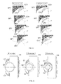
- FIG. 5 a schematic view of sliding profiles according to the invention is depicted.
- the first sliding profile SP1, the first clamp contact CC1 and the first rib CR1 are depicted in various positions, said positions illustrating the course of first clamp contact CC1 while the first sliding profile moves towards the first clamp C1.
- the first sliding profile SP1 is designed with a profile of a positive interior curving.
- the first clamp contact CC1 follows a course on the first rib CR1 and on the first sliding profile SP1. Said course of the first clamp contact CC1 is dependent on the positive interior curving profile of the first sliding profile SP1.
- the first sliding profile SP1 is designed with a profile of a negative interior curving.
- the first clamp contact CC1 follows a course on the first rib CR1 and on the first sliding profile SP1. Said course of the first clamp contact CC1 is dependent on the positive interior curving profile of the first sliding profile SP1.
- the first sliding profile SP1 is designed with a profile of a linear curving, or with a profile of a positive external curving, or with a profile of a wave interior curving.
- FIG. 6 a schematic view of a fourth example of a fixing system and tubular support structures according to the invention is depicted.
- Said schematic view is a cross-sectional view of the fourth example of the fixing system FS adapted on tubular support structures with varying diameters.
- the support structure S2 is a pipe with a diameter of 90mm, on which the first clamp C1 and the second clamp C2 are clamped for attaching the fixing system FS to said pipe.
- the support structure S2 is a pipe with a diameter of 70mm, on which the first clamp C1 and the second clamp C2 are clamped for attaching the fixing system FS to said pipe.
- the support structure S2 is a pipe with a diameter of 50mm, on which the first clamp C1 and the second clamp C2 are clamped for attaching the fixing system FS to said pipe.
- the support structure S2 is a positive conical pipe or a negative conical pipe.
- the same fixing system FS is advantageously adapted to be fixed to various sized support structure S2.
- FIG. 7 a schematic view of a first clamp, a second clamp and support structures is depicted.
- Said schematic view is a cross-sectional view of the first clamp C1 and the second clamp C2, clamped on support structures S2 with varying cross-sectional profiles.
- the first clamp C1 and the second clamp C2 are clamping the support structure S2, said support structure S2 is designed with a square section profile.
- the first clamp C1 and the second clamp C2 are clamping the support structure S2, said support structure S2 is designed with a rectangular section profile.
- the first clamp C1 and the second clamp C2 are clamping the support structure S2, said support structure S2 is designed with another rectangular section profile.
- the first clamp C1 and the second clamp C2 are clamping the support structure S2, said support structure S2 is designed with a 'L' shaped section profile.
- the first clamp C1 and the second clamp C2 are clamping the support structure S2, said support structure S2 is designed with an ovoid shaped section profile.
- the first clamp C1 and the second clamp C2 are clamping the support structure S2, said support structure S2 is designed with a 'T' shaped section profile.
- the fixing system FS is advantageously adapted to be fixed to support structure S2 with various shapes.
- the fixing system FS preferably comprises a majority of aluminum that advantageously offers a good compromise of robustness and weight in a non limiting example.
- the fixing system FS comprises a majority of plastic.
- the fixing system FS comprises a combination of aluminum elements and plastic elements.
- the fixing system FS is a system for holding the first structure S1 on the support structure S2.
- the fixing system FS is a reliable system to be clamped on the support structure S2 located on the reception area RA. Indeed said fixing system FS comprises a small number of mechanical parts. A small number of mechanical parts reduces the risk of aging or damages incurred by environment compared to a system comprising many parts, and makes the fixing system FS more reliable.
- the small number of parts of the fixing system FS is also beneficial in terms of human operations to use said fixing system FS. Compared to other systems, less tools, screws, nuts etc are needed to have an effective clamping.
- the fixing system FS converts the movement of the locket push LP towards the clamps (C1; C2; C3; C4), into the translation movements of the clamps towards the support structure S2. Said conversion profitably reduces the human effort to firmly fix the first structure S1 on the support structure S2.
- the fixing system FS is advantageously adapted to equitably split the mechanical stress of the clamping, which improves the lifetime of the fixing system FS.
- the first clamp C1 and the second clamp C2 are two clamps designed with the same properties and shapes, as the fixing system FS advantageously allows using the same clamp in the first clamp C1's position, or in the second clamp C2's position. Such flexibility reduces manufacturing costs of the fixing system FS. It eases also installation of the fixing system FS.
- the fixing system FS is advantageous to be used in various kind of support structure S2.
- the fixing system FS is able to hold the first structure S1 on the support structure S2, said support structure S2 being a mast, a standard pipe, a positive or negative conical pipe etc.
- the fixing system FS is a robust and flexible solution to fix the first structure S1 on the support structure S2.
Landscapes
- Engineering & Computer Science (AREA)
- General Engineering & Computer Science (AREA)
- Mechanical Engineering (AREA)
- Clamps And Clips (AREA)
Priority Applications (1)
| Application Number | Priority Date | Filing Date | Title |
|---|---|---|---|
| EP14171582.1A EP2953205B1 (fr) | 2014-06-06 | 2014-06-06 | Système de fixation d'une structure sur une autre structure |
Applications Claiming Priority (1)
| Application Number | Priority Date | Filing Date | Title |
|---|---|---|---|
| EP14171582.1A EP2953205B1 (fr) | 2014-06-06 | 2014-06-06 | Système de fixation d'une structure sur une autre structure |
Publications (2)
| Publication Number | Publication Date |
|---|---|
| EP2953205A1 true EP2953205A1 (fr) | 2015-12-09 |
| EP2953205B1 EP2953205B1 (fr) | 2021-04-07 |
Family
ID=50943103
Family Applications (1)
| Application Number | Title | Priority Date | Filing Date |
|---|---|---|---|
| EP14171582.1A Active EP2953205B1 (fr) | 2014-06-06 | 2014-06-06 | Système de fixation d'une structure sur une autre structure |
Country Status (1)
| Country | Link |
|---|---|
| EP (1) | EP2953205B1 (fr) |
Cited By (1)
| Publication number | Priority date | Publication date | Assignee | Title |
|---|---|---|---|---|
| CN105627241A (zh) * | 2016-03-21 | 2016-06-01 | 江苏工程职业技术学院 | 一种空气储能光伏led路灯系统及控制方法 |
Families Citing this family (2)
| Publication number | Priority date | Publication date | Assignee | Title |
|---|---|---|---|---|
| FR3158613B1 (fr) * | 2024-01-29 | 2025-12-26 | Tchaomegot Collecte | cendrier urbain pour la collecte des mégots de cigarettes comprenant des moyens de fixation s’adaptant à tous types de poteaux. |
| WO2025162791A1 (fr) * | 2024-01-29 | 2025-08-07 | Tchaomegot Collecte | Bride de fixation adaptable à tout type de poteaux |
Citations (5)
| Publication number | Priority date | Publication date | Assignee | Title |
|---|---|---|---|---|
| US6222504B1 (en) * | 2000-01-14 | 2001-04-24 | Omnipoint Corporation | Adjustable antenna mount with rotatable antenna brackets for PCS and other antennas |
| US20090139156A1 (en) * | 2007-11-29 | 2009-06-04 | Thomas & Betts International, Inc | Fast beam clamp |
| US20110233373A1 (en) * | 2008-12-19 | 2011-09-29 | Huawei Technologies Co., Ltd. | Fixing device for a holding pole |
| US20140014797A1 (en) * | 2012-07-13 | 2014-01-16 | Gorilla Forks, LLC | Universal clamping assembly and accessories therefor |
| EP2713435A1 (fr) * | 2012-09-28 | 2014-04-02 | Alcatel Lucent | Système de montage d'une antenne sur un support cylindrique |
Family Cites Families (1)
| Publication number | Priority date | Publication date | Assignee | Title |
|---|---|---|---|---|
| US5867132A (en) * | 1996-09-09 | 1999-02-02 | Endgate Corporation | Adjustable antenna mounting assembly |
-
2014
- 2014-06-06 EP EP14171582.1A patent/EP2953205B1/fr active Active
Patent Citations (5)
| Publication number | Priority date | Publication date | Assignee | Title |
|---|---|---|---|---|
| US6222504B1 (en) * | 2000-01-14 | 2001-04-24 | Omnipoint Corporation | Adjustable antenna mount with rotatable antenna brackets for PCS and other antennas |
| US20090139156A1 (en) * | 2007-11-29 | 2009-06-04 | Thomas & Betts International, Inc | Fast beam clamp |
| US20110233373A1 (en) * | 2008-12-19 | 2011-09-29 | Huawei Technologies Co., Ltd. | Fixing device for a holding pole |
| US20140014797A1 (en) * | 2012-07-13 | 2014-01-16 | Gorilla Forks, LLC | Universal clamping assembly and accessories therefor |
| EP2713435A1 (fr) * | 2012-09-28 | 2014-04-02 | Alcatel Lucent | Système de montage d'une antenne sur un support cylindrique |
Cited By (2)
| Publication number | Priority date | Publication date | Assignee | Title |
|---|---|---|---|---|
| CN105627241A (zh) * | 2016-03-21 | 2016-06-01 | 江苏工程职业技术学院 | 一种空气储能光伏led路灯系统及控制方法 |
| CN105627241B (zh) * | 2016-03-21 | 2018-06-19 | 江苏工程职业技术学院 | 一种空气储能光伏led路灯系统及控制方法 |
Also Published As
| Publication number | Publication date |
|---|---|
| EP2953205B1 (fr) | 2021-04-07 |
Similar Documents
| Publication | Publication Date | Title |
|---|---|---|
| US11264696B2 (en) | Multi-antenna mounting device and multi-antenna assembly | |
| EP2953205B1 (fr) | Système de fixation d'une structure sur une autre structure | |
| CN105990686A (zh) | 具有可旋转的发射元件的天线 | |
| US20100288897A1 (en) | Adjustable pole mount | |
| US10971794B2 (en) | Antenna mounting bracket assembly | |
| US10177433B2 (en) | Low-profile mounting apparatus for antenna systems | |
| US20250028133A1 (en) | Positioning fixture for fixing end face structure of optical fiber splice closure | |
| RU2461924C1 (ru) | Устройство для крепления элементов антенн | |
| KR20170129550A (ko) | 등기구 암 멀티고정수단 | |
| US20180299031A1 (en) | Systems and methods for a pipeline anchor lug sleeve and link | |
| CN209943687U (zh) | 一种室内管线的固定装置 | |
| EP3853523B1 (fr) | Fixation de luminaire | |
| US12424734B2 (en) | Base station antenna and supporting device for base station antenna | |
| EP2403083A1 (fr) | Guide de câbles, étrier et assemblage associé pour positionner et tenir des câbles sur des supports fixes | |
| US20190372194A1 (en) | Antenna assembly | |
| JP2016017600A (ja) | 伸縮可撓継手及びその取り付け方法 | |
| RU190300U1 (ru) | Устройство для предотвращения посадки птиц на сооружения | |
| CN203119082U (zh) | 多用途天线架 | |
| US20170352940A1 (en) | Installation bracket | |
| KR102098608B1 (ko) | 진동 저감용 배관 지지장치 | |
| CN108360906B (zh) | 一种航空航天用塔架加固装置 | |
| CN115313535B (zh) | 安装结构 | |
| EP2381047A2 (fr) | Lampe pour une lucarne tubulaire | |
| CN104369144A (zh) | 一种螺栓拧紧装置 | |
| CN204857926U (zh) | 一种具有多个可移动馈源的天线 |
Legal Events
| Date | Code | Title | Description |
|---|---|---|---|
| PUAI | Public reference made under article 153(3) epc to a published international application that has entered the european phase |
Free format text: ORIGINAL CODE: 0009012 |
|
| AK | Designated contracting states |
Kind code of ref document: A1 Designated state(s): AL AT BE BG CH CY CZ DE DK EE ES FI FR GB GR HR HU IE IS IT LI LT LU LV MC MK MT NL NO PL PT RO RS SE SI SK SM TR |
|
| AX | Request for extension of the european patent |
Extension state: BA ME |
|
| 17P | Request for examination filed |
Effective date: 20160609 |
|
| RBV | Designated contracting states (corrected) |
Designated state(s): AL AT BE BG CH CY CZ DE DK EE ES FI FR GB GR HR HU IE IS IT LI LT LU LV MC MK MT NL NO PL PT RO RS SE SI SK SM TR |
|
| STAA | Information on the status of an ep patent application or granted ep patent |
Free format text: STATUS: EXAMINATION IS IN PROGRESS |
|
| 17Q | First examination report despatched |
Effective date: 20190628 |
|
| GRAP | Despatch of communication of intention to grant a patent |
Free format text: ORIGINAL CODE: EPIDOSNIGR1 |
|
| STAA | Information on the status of an ep patent application or granted ep patent |
Free format text: STATUS: GRANT OF PATENT IS INTENDED |
|
| INTG | Intention to grant announced |
Effective date: 20210115 |
|
| RIN1 | Information on inventor provided before grant (corrected) |
Inventor name: VANETTI, LOIC Inventor name: TUAU, DENIS |
|
| GRAS | Grant fee paid |
Free format text: ORIGINAL CODE: EPIDOSNIGR3 |
|
| GRAA | (expected) grant |
Free format text: ORIGINAL CODE: 0009210 |
|
| STAA | Information on the status of an ep patent application or granted ep patent |
Free format text: STATUS: THE PATENT HAS BEEN GRANTED |
|
| AK | Designated contracting states |
Kind code of ref document: B1 Designated state(s): AL AT BE BG CH CY CZ DE DK EE ES FI FR GB GR HR HU IE IS IT LI LT LU LV MC MK MT NL NO PL PT RO RS SE SI SK SM TR |
|
| REG | Reference to a national code |
Ref country code: GB Ref legal event code: FG4D |
|
| REG | Reference to a national code |
Ref country code: AT Ref legal event code: REF Ref document number: 1380861 Country of ref document: AT Kind code of ref document: T Effective date: 20210415 Ref country code: CH Ref legal event code: EP |
|
| REG | Reference to a national code |
Ref country code: DE Ref legal event code: R096 Ref document number: 602014076308 Country of ref document: DE |
|
| REG | Reference to a national code |
Ref country code: IE Ref legal event code: FG4D |
|
| REG | Reference to a national code |
Ref country code: LT Ref legal event code: MG9D |
|
| REG | Reference to a national code |
Ref country code: NL Ref legal event code: MP Effective date: 20210407 Ref country code: AT Ref legal event code: MK05 Ref document number: 1380861 Country of ref document: AT Kind code of ref document: T Effective date: 20210407 |
|
| PG25 | Lapsed in a contracting state [announced via postgrant information from national office to epo] |
Ref country code: AT Free format text: LAPSE BECAUSE OF FAILURE TO SUBMIT A TRANSLATION OF THE DESCRIPTION OR TO PAY THE FEE WITHIN THE PRESCRIBED TIME-LIMIT Effective date: 20210407 Ref country code: BG Free format text: LAPSE BECAUSE OF FAILURE TO SUBMIT A TRANSLATION OF THE DESCRIPTION OR TO PAY THE FEE WITHIN THE PRESCRIBED TIME-LIMIT Effective date: 20210707 Ref country code: FI Free format text: LAPSE BECAUSE OF FAILURE TO SUBMIT A TRANSLATION OF THE DESCRIPTION OR TO PAY THE FEE WITHIN THE PRESCRIBED TIME-LIMIT Effective date: 20210407 Ref country code: NL Free format text: LAPSE BECAUSE OF FAILURE TO SUBMIT A TRANSLATION OF THE DESCRIPTION OR TO PAY THE FEE WITHIN THE PRESCRIBED TIME-LIMIT Effective date: 20210407 Ref country code: LT Free format text: LAPSE BECAUSE OF FAILURE TO SUBMIT A TRANSLATION OF THE DESCRIPTION OR TO PAY THE FEE WITHIN THE PRESCRIBED TIME-LIMIT Effective date: 20210407 Ref country code: HR Free format text: LAPSE BECAUSE OF FAILURE TO SUBMIT A TRANSLATION OF THE DESCRIPTION OR TO PAY THE FEE WITHIN THE PRESCRIBED TIME-LIMIT Effective date: 20210407 |
|
| PG25 | Lapsed in a contracting state [announced via postgrant information from national office to epo] |
Ref country code: GR Free format text: LAPSE BECAUSE OF FAILURE TO SUBMIT A TRANSLATION OF THE DESCRIPTION OR TO PAY THE FEE WITHIN THE PRESCRIBED TIME-LIMIT Effective date: 20210708 Ref country code: IS Free format text: LAPSE BECAUSE OF FAILURE TO SUBMIT A TRANSLATION OF THE DESCRIPTION OR TO PAY THE FEE WITHIN THE PRESCRIBED TIME-LIMIT Effective date: 20210807 Ref country code: LV Free format text: LAPSE BECAUSE OF FAILURE TO SUBMIT A TRANSLATION OF THE DESCRIPTION OR TO PAY THE FEE WITHIN THE PRESCRIBED TIME-LIMIT Effective date: 20210407 Ref country code: ES Free format text: LAPSE BECAUSE OF FAILURE TO SUBMIT A TRANSLATION OF THE DESCRIPTION OR TO PAY THE FEE WITHIN THE PRESCRIBED TIME-LIMIT Effective date: 20210407 Ref country code: PL Free format text: LAPSE BECAUSE OF FAILURE TO SUBMIT A TRANSLATION OF THE DESCRIPTION OR TO PAY THE FEE WITHIN THE PRESCRIBED TIME-LIMIT Effective date: 20210407 Ref country code: NO Free format text: LAPSE BECAUSE OF FAILURE TO SUBMIT A TRANSLATION OF THE DESCRIPTION OR TO PAY THE FEE WITHIN THE PRESCRIBED TIME-LIMIT Effective date: 20210707 Ref country code: PT Free format text: LAPSE BECAUSE OF FAILURE TO SUBMIT A TRANSLATION OF THE DESCRIPTION OR TO PAY THE FEE WITHIN THE PRESCRIBED TIME-LIMIT Effective date: 20210809 Ref country code: RS Free format text: LAPSE BECAUSE OF FAILURE TO SUBMIT A TRANSLATION OF THE DESCRIPTION OR TO PAY THE FEE WITHIN THE PRESCRIBED TIME-LIMIT Effective date: 20210407 Ref country code: SE Free format text: LAPSE BECAUSE OF FAILURE TO SUBMIT A TRANSLATION OF THE DESCRIPTION OR TO PAY THE FEE WITHIN THE PRESCRIBED TIME-LIMIT Effective date: 20210407 |
|
| REG | Reference to a national code |
Ref country code: DE Ref legal event code: R097 Ref document number: 602014076308 Country of ref document: DE |
|
| PG25 | Lapsed in a contracting state [announced via postgrant information from national office to epo] |
Ref country code: MC Free format text: LAPSE BECAUSE OF FAILURE TO SUBMIT A TRANSLATION OF THE DESCRIPTION OR TO PAY THE FEE WITHIN THE PRESCRIBED TIME-LIMIT Effective date: 20210407 Ref country code: RO Free format text: LAPSE BECAUSE OF FAILURE TO SUBMIT A TRANSLATION OF THE DESCRIPTION OR TO PAY THE FEE WITHIN THE PRESCRIBED TIME-LIMIT Effective date: 20210407 Ref country code: SM Free format text: LAPSE BECAUSE OF FAILURE TO SUBMIT A TRANSLATION OF THE DESCRIPTION OR TO PAY THE FEE WITHIN THE PRESCRIBED TIME-LIMIT Effective date: 20210407 Ref country code: SK Free format text: LAPSE BECAUSE OF FAILURE TO SUBMIT A TRANSLATION OF THE DESCRIPTION OR TO PAY THE FEE WITHIN THE PRESCRIBED TIME-LIMIT Effective date: 20210407 Ref country code: EE Free format text: LAPSE BECAUSE OF FAILURE TO SUBMIT A TRANSLATION OF THE DESCRIPTION OR TO PAY THE FEE WITHIN THE PRESCRIBED TIME-LIMIT Effective date: 20210407 Ref country code: DK Free format text: LAPSE BECAUSE OF FAILURE TO SUBMIT A TRANSLATION OF THE DESCRIPTION OR TO PAY THE FEE WITHIN THE PRESCRIBED TIME-LIMIT Effective date: 20210407 Ref country code: CZ Free format text: LAPSE BECAUSE OF FAILURE TO SUBMIT A TRANSLATION OF THE DESCRIPTION OR TO PAY THE FEE WITHIN THE PRESCRIBED TIME-LIMIT Effective date: 20210407 |
|
| REG | Reference to a national code |
Ref country code: CH Ref legal event code: PL |
|
| PLBE | No opposition filed within time limit |
Free format text: ORIGINAL CODE: 0009261 |
|
| STAA | Information on the status of an ep patent application or granted ep patent |
Free format text: STATUS: NO OPPOSITION FILED WITHIN TIME LIMIT |
|
| REG | Reference to a national code |
Ref country code: BE Ref legal event code: MM Effective date: 20210630 |
|
| 26N | No opposition filed |
Effective date: 20220110 |
|
| PG25 | Lapsed in a contracting state [announced via postgrant information from national office to epo] |
Ref country code: LU Free format text: LAPSE BECAUSE OF NON-PAYMENT OF DUE FEES Effective date: 20210606 |
|
| PG25 | Lapsed in a contracting state [announced via postgrant information from national office to epo] |
Ref country code: LI Free format text: LAPSE BECAUSE OF NON-PAYMENT OF DUE FEES Effective date: 20210630 Ref country code: IE Free format text: LAPSE BECAUSE OF NON-PAYMENT OF DUE FEES Effective date: 20210606 Ref country code: CH Free format text: LAPSE BECAUSE OF NON-PAYMENT OF DUE FEES Effective date: 20210630 |
|
| PG25 | Lapsed in a contracting state [announced via postgrant information from national office to epo] |
Ref country code: IS Free format text: LAPSE BECAUSE OF FAILURE TO SUBMIT A TRANSLATION OF THE DESCRIPTION OR TO PAY THE FEE WITHIN THE PRESCRIBED TIME-LIMIT Effective date: 20210807 Ref country code: FR Free format text: LAPSE BECAUSE OF NON-PAYMENT OF DUE FEES Effective date: 20210607 Ref country code: AL Free format text: LAPSE BECAUSE OF FAILURE TO SUBMIT A TRANSLATION OF THE DESCRIPTION OR TO PAY THE FEE WITHIN THE PRESCRIBED TIME-LIMIT Effective date: 20210407 |
|
| PG25 | Lapsed in a contracting state [announced via postgrant information from national office to epo] |
Ref country code: IT Free format text: LAPSE BECAUSE OF FAILURE TO SUBMIT A TRANSLATION OF THE DESCRIPTION OR TO PAY THE FEE WITHIN THE PRESCRIBED TIME-LIMIT Effective date: 20210407 Ref country code: BE Free format text: LAPSE BECAUSE OF NON-PAYMENT OF DUE FEES Effective date: 20210630 |
|
| PG25 | Lapsed in a contracting state [announced via postgrant information from national office to epo] |
Ref country code: HU Free format text: LAPSE BECAUSE OF FAILURE TO SUBMIT A TRANSLATION OF THE DESCRIPTION OR TO PAY THE FEE WITHIN THE PRESCRIBED TIME-LIMIT; INVALID AB INITIO Effective date: 20140606 |
|
| PG25 | Lapsed in a contracting state [announced via postgrant information from national office to epo] |
Ref country code: CY Free format text: LAPSE BECAUSE OF FAILURE TO SUBMIT A TRANSLATION OF THE DESCRIPTION OR TO PAY THE FEE WITHIN THE PRESCRIBED TIME-LIMIT Effective date: 20210407 |
|
| PG25 | Lapsed in a contracting state [announced via postgrant information from national office to epo] |
Ref country code: MK Free format text: LAPSE BECAUSE OF FAILURE TO SUBMIT A TRANSLATION OF THE DESCRIPTION OR TO PAY THE FEE WITHIN THE PRESCRIBED TIME-LIMIT Effective date: 20210407 |
|
| PG25 | Lapsed in a contracting state [announced via postgrant information from national office to epo] |
Ref country code: MT Free format text: LAPSE BECAUSE OF FAILURE TO SUBMIT A TRANSLATION OF THE DESCRIPTION OR TO PAY THE FEE WITHIN THE PRESCRIBED TIME-LIMIT Effective date: 20210407 |
|
| PGFP | Annual fee paid to national office [announced via postgrant information from national office to epo] |
Ref country code: DE Payment date: 20250429 Year of fee payment: 12 |
|
| PGFP | Annual fee paid to national office [announced via postgrant information from national office to epo] |
Ref country code: GB Payment date: 20250501 Year of fee payment: 12 |
|
| PG25 | Lapsed in a contracting state [announced via postgrant information from national office to epo] |
Ref country code: TR Free format text: LAPSE BECAUSE OF FAILURE TO SUBMIT A TRANSLATION OF THE DESCRIPTION OR TO PAY THE FEE WITHIN THE PRESCRIBED TIME-LIMIT Effective date: 20210407 |
|
| REG | Reference to a national code |
Ref country code: DE Ref legal event code: R081 Ref document number: 602014076308 Country of ref document: DE Owner name: ALCATEL-LUCENT SHANGHAI BELL CO., LTD., CN Free format text: FORMER OWNER: ALCATEL- LUCENT SHANGHAI BELL CO., LTD, PARIS, FR Ref country code: DE Ref legal event code: R081 Ref document number: 602014076308 Country of ref document: DE Owner name: NOKIA SOLUTIONS (SHANGHAI) CO., LTD., CN Free format text: FORMER OWNER: ALCATEL- LUCENT SHANGHAI BELL CO., LTD, PARIS, FR |
|
| REG | Reference to a national code |
Ref country code: DE Ref legal event code: R081 Ref document number: 602014076308 Country of ref document: DE Owner name: NOKIA SOLUTIONS (SHANGHAI) CO., LTD., CN Free format text: FORMER OWNER: ALCATEL-LUCENT SHANGHAI BELL CO., LTD., SHANGHAI, CN |