EP2953227B1 - Réseau de bord pour un véhicule automobile - Google Patents
Réseau de bord pour un véhicule automobile Download PDFInfo
- Publication number
- EP2953227B1 EP2953227B1 EP15001273.0A EP15001273A EP2953227B1 EP 2953227 B1 EP2953227 B1 EP 2953227B1 EP 15001273 A EP15001273 A EP 15001273A EP 2953227 B1 EP2953227 B1 EP 2953227B1
- Authority
- EP
- European Patent Office
- Prior art keywords
- voltage
- switch
- subsystem
- energy store
- network
- Prior art date
- Legal status (The legal status is an assumption and is not a legal conclusion. Google has not performed a legal analysis and makes no representation as to the accuracy of the status listed.)
- Active
Links
Images



Classifications
-
- B—PERFORMING OPERATIONS; TRANSPORTING
- B60—VEHICLES IN GENERAL
- B60L—PROPULSION OF ELECTRICALLY-PROPELLED VEHICLES; SUPPLYING ELECTRIC POWER FOR AUXILIARY EQUIPMENT OF ELECTRICALLY-PROPELLED VEHICLES; ELECTRODYNAMIC BRAKE SYSTEMS FOR VEHICLES IN GENERAL; MAGNETIC SUSPENSION OR LEVITATION FOR VEHICLES; MONITORING OPERATING VARIABLES OF ELECTRICALLY-PROPELLED VEHICLES; ELECTRIC SAFETY DEVICES FOR ELECTRICALLY-PROPELLED VEHICLES
- B60L1/00—Supplying electric power to auxiliary equipment of vehicles
- B60L1/003—Supplying electric power to auxiliary equipment of vehicles to auxiliary motors, e.g. for pumps, compressors
-
- B—PERFORMING OPERATIONS; TRANSPORTING
- B60—VEHICLES IN GENERAL
- B60L—PROPULSION OF ELECTRICALLY-PROPELLED VEHICLES; SUPPLYING ELECTRIC POWER FOR AUXILIARY EQUIPMENT OF ELECTRICALLY-PROPELLED VEHICLES; ELECTRODYNAMIC BRAKE SYSTEMS FOR VEHICLES IN GENERAL; MAGNETIC SUSPENSION OR LEVITATION FOR VEHICLES; MONITORING OPERATING VARIABLES OF ELECTRICALLY-PROPELLED VEHICLES; ELECTRIC SAFETY DEVICES FOR ELECTRICALLY-PROPELLED VEHICLES
- B60L3/00—Electric devices on electrically-propelled vehicles for safety purposes; Monitoring operating variables, e.g. speed, deceleration or energy consumption
- B60L3/04—Cutting off the power supply under fault conditions
-
- B—PERFORMING OPERATIONS; TRANSPORTING
- B60—VEHICLES IN GENERAL
- B60R—VEHICLES, VEHICLE FITTINGS, OR VEHICLE PARTS, NOT OTHERWISE PROVIDED FOR
- B60R16/00—Electric or fluid circuits specially adapted for vehicles and not otherwise provided for; Arrangement of elements of electric or fluid circuits specially adapted for vehicles and not otherwise provided for
- B60R16/02—Electric or fluid circuits specially adapted for vehicles and not otherwise provided for; Arrangement of elements of electric or fluid circuits specially adapted for vehicles and not otherwise provided for electric constitutive elements
- B60R16/03—Electric or fluid circuits specially adapted for vehicles and not otherwise provided for; Arrangement of elements of electric or fluid circuits specially adapted for vehicles and not otherwise provided for electric constitutive elements for supply of electrical power to vehicle subsystems or for
-
- H—ELECTRICITY
- H02—GENERATION; CONVERSION OR DISTRIBUTION OF ELECTRIC POWER
- H02J—ELECTRIC POWER NETWORKS; CIRCUIT ARRANGEMENTS OR SYSTEMS FOR SUPPLYING OR DISTRIBUTING ELECTRIC POWER; SYSTEMS FOR STORING ELECTRIC ENERGY
- H02J1/00—Circuit arrangements for DC mains or DC distribution networks
- H02J1/08—Three-wire DC power distribution systems; Systems having more than three wires
- H02J1/082—DC supplies with two or more different DC voltage levels
-
- H—ELECTRICITY
- H02—GENERATION; CONVERSION OR DISTRIBUTION OF ELECTRIC POWER
- H02J—ELECTRIC POWER NETWORKS; CIRCUIT ARRANGEMENTS OR SYSTEMS FOR SUPPLYING OR DISTRIBUTING ELECTRIC POWER; SYSTEMS FOR STORING ELECTRIC ENERGY
- H02J7/00—Circuit arrangements for charging or discharging batteries or for supplying loads from batteries
- H02J7/34—Parallel operation in networks using both storage and other DC sources, e.g. providing buffering
- H02J7/342—The other DC source being a battery actively interacting with the first one, i.e. battery to battery charging
-
- B—PERFORMING OPERATIONS; TRANSPORTING
- B60—VEHICLES IN GENERAL
- B60L—PROPULSION OF ELECTRICALLY-PROPELLED VEHICLES; SUPPLYING ELECTRIC POWER FOR AUXILIARY EQUIPMENT OF ELECTRICALLY-PROPELLED VEHICLES; ELECTRODYNAMIC BRAKE SYSTEMS FOR VEHICLES IN GENERAL; MAGNETIC SUSPENSION OR LEVITATION FOR VEHICLES; MONITORING OPERATING VARIABLES OF ELECTRICALLY-PROPELLED VEHICLES; ELECTRIC SAFETY DEVICES FOR ELECTRICALLY-PROPELLED VEHICLES
- B60L2210/00—Converter types
- B60L2210/10—DC to DC converters
-
- B—PERFORMING OPERATIONS; TRANSPORTING
- B60—VEHICLES IN GENERAL
- B60L—PROPULSION OF ELECTRICALLY-PROPELLED VEHICLES; SUPPLYING ELECTRIC POWER FOR AUXILIARY EQUIPMENT OF ELECTRICALLY-PROPELLED VEHICLES; ELECTRODYNAMIC BRAKE SYSTEMS FOR VEHICLES IN GENERAL; MAGNETIC SUSPENSION OR LEVITATION FOR VEHICLES; MONITORING OPERATING VARIABLES OF ELECTRICALLY-PROPELLED VEHICLES; ELECTRIC SAFETY DEVICES FOR ELECTRICALLY-PROPELLED VEHICLES
- B60L2240/00—Control parameters of input or output; Target parameters
- B60L2240/40—Drive Train control parameters
- B60L2240/42—Drive Train control parameters related to electric machines
- B60L2240/427—Voltage
-
- B—PERFORMING OPERATIONS; TRANSPORTING
- B60—VEHICLES IN GENERAL
- B60L—PROPULSION OF ELECTRICALLY-PROPELLED VEHICLES; SUPPLYING ELECTRIC POWER FOR AUXILIARY EQUIPMENT OF ELECTRICALLY-PROPELLED VEHICLES; ELECTRODYNAMIC BRAKE SYSTEMS FOR VEHICLES IN GENERAL; MAGNETIC SUSPENSION OR LEVITATION FOR VEHICLES; MONITORING OPERATING VARIABLES OF ELECTRICALLY-PROPELLED VEHICLES; ELECTRIC SAFETY DEVICES FOR ELECTRICALLY-PROPELLED VEHICLES
- B60L2240/00—Control parameters of input or output; Target parameters
- B60L2240/40—Drive Train control parameters
- B60L2240/52—Drive Train control parameters related to converters
- B60L2240/527—Voltage
-
- B—PERFORMING OPERATIONS; TRANSPORTING
- B60—VEHICLES IN GENERAL
- B60L—PROPULSION OF ELECTRICALLY-PROPELLED VEHICLES; SUPPLYING ELECTRIC POWER FOR AUXILIARY EQUIPMENT OF ELECTRICALLY-PROPELLED VEHICLES; ELECTRODYNAMIC BRAKE SYSTEMS FOR VEHICLES IN GENERAL; MAGNETIC SUSPENSION OR LEVITATION FOR VEHICLES; MONITORING OPERATING VARIABLES OF ELECTRICALLY-PROPELLED VEHICLES; ELECTRIC SAFETY DEVICES FOR ELECTRICALLY-PROPELLED VEHICLES
- B60L2240/00—Control parameters of input or output; Target parameters
- B60L2240/40—Drive Train control parameters
- B60L2240/54—Drive Train control parameters related to batteries
- B60L2240/547—Voltage
-
- H—ELECTRICITY
- H02—GENERATION; CONVERSION OR DISTRIBUTION OF ELECTRIC POWER
- H02J—ELECTRIC POWER NETWORKS; CIRCUIT ARRANGEMENTS OR SYSTEMS FOR SUPPLYING OR DISTRIBUTING ELECTRIC POWER; SYSTEMS FOR STORING ELECTRIC ENERGY
- H02J2105/00—Networks for supplying or distributing electric power characterised by their spatial reach or by the load
- H02J2105/30—Networks for supplying or distributing electric power characterised by their spatial reach or by the load the load networks being external to vehicles, i.e. exchanging power with vehicles
- H02J2105/33—Networks for supplying or distributing electric power characterised by their spatial reach or by the load the load networks being external to vehicles, i.e. exchanging power with vehicles exchanging power with road vehicles
-
- H—ELECTRICITY
- H02—GENERATION; CONVERSION OR DISTRIBUTION OF ELECTRIC POWER
- H02J—ELECTRIC POWER NETWORKS; CIRCUIT ARRANGEMENTS OR SYSTEMS FOR SUPPLYING OR DISTRIBUTING ELECTRIC POWER; SYSTEMS FOR STORING ELECTRIC ENERGY
- H02J7/00—Circuit arrangements for charging or discharging batteries or for supplying loads from batteries
- H02J7/14—Circuit arrangements for charging or discharging batteries or for supplying loads from batteries for charging batteries from dynamo-electric generators driven at varying speed, e.g. on vehicle
-
- H—ELECTRICITY
- H02—GENERATION; CONVERSION OR DISTRIBUTION OF ELECTRIC POWER
- H02J—ELECTRIC POWER NETWORKS; CIRCUIT ARRANGEMENTS OR SYSTEMS FOR SUPPLYING OR DISTRIBUTING ELECTRIC POWER; SYSTEMS FOR STORING ELECTRIC ENERGY
- H02J7/00—Circuit arrangements for charging or discharging batteries or for supplying loads from batteries
- H02J7/34—Parallel operation in networks using both storage and other DC sources, e.g. providing buffering
- H02J7/345—Parallel operation in networks using both storage and other DC sources, e.g. providing buffering using capacitors as storage or buffering devices
-
- Y—GENERAL TAGGING OF NEW TECHNOLOGICAL DEVELOPMENTS; GENERAL TAGGING OF CROSS-SECTIONAL TECHNOLOGIES SPANNING OVER SEVERAL SECTIONS OF THE IPC; TECHNICAL SUBJECTS COVERED BY FORMER USPC CROSS-REFERENCE ART COLLECTIONS [XRACs] AND DIGESTS
- Y02—TECHNOLOGIES OR APPLICATIONS FOR MITIGATION OR ADAPTATION AGAINST CLIMATE CHANGE
- Y02T—CLIMATE CHANGE MITIGATION TECHNOLOGIES RELATED TO TRANSPORTATION
- Y02T10/00—Road transport of goods or passengers
- Y02T10/60—Other road transportation technologies with climate change mitigation effect
- Y02T10/64—Electric machine technologies in electromobility
-
- Y—GENERAL TAGGING OF NEW TECHNOLOGICAL DEVELOPMENTS; GENERAL TAGGING OF CROSS-SECTIONAL TECHNOLOGIES SPANNING OVER SEVERAL SECTIONS OF THE IPC; TECHNICAL SUBJECTS COVERED BY FORMER USPC CROSS-REFERENCE ART COLLECTIONS [XRACs] AND DIGESTS
- Y02—TECHNOLOGIES OR APPLICATIONS FOR MITIGATION OR ADAPTATION AGAINST CLIMATE CHANGE
- Y02T—CLIMATE CHANGE MITIGATION TECHNOLOGIES RELATED TO TRANSPORTATION
- Y02T10/00—Road transport of goods or passengers
- Y02T10/60—Other road transportation technologies with climate change mitigation effect
- Y02T10/72—Electric energy management in electromobility
Definitions
- the invention relates to an electrical system for a motor vehicle, in particular for a commercial vehicle, according to claim 1.
- vehicle electrical systems In order to supply different consumers via a network, vehicle electrical systems recently developed have a second voltage level in addition to a first one.
- the first and second voltage levels are coupled to one another via a voltage converter.
- consumers with low power consumption are connected to the first sub-network with the lower nominal voltage (e.g. 24 V).
- a first energy store can be provided.
- High-performance consumers, a generator and a second energy store can be connected to the second sub-network with the higher nominal voltage (e.g. 48 V).
- low-voltage consumers can optionally be supplied from the second sub-network.
- the generator can be a so-called multi-voltage generator (MVG), which generates a high or a low voltage depending on the voltage applied to its excitation coil and supplies the two sub-networks with electrical power.
- MVG multi-voltage generator
- the generator as an electrical starter generator, e.g. B. is designed as a crankshaft starter generator, this can be used for starting the engine.
- a voltage (DC / DC) converter which is able to transfer energy between the networks, is usually installed between these subnetworks to couple the two subnetworks.
- a characteristic of this DC / DC converter is that it has a maximum and minimum output and input voltage for the respective sides.
- Is z. B. installed a memory z. B. has a high self-discharge when parking the vehicle or is mounted in the unloaded state in the vehicle, this must be charged or preconditioned. In a typical application of the 24V / 12V network with a lead acid battery, this is done by the alternator. If the storage is not a lead-acid battery or there is no alternator in the affected electrical system, the DC / DC converter must be used for pre-charging.
- DC / DC converter is subject to increased requirements for the output voltage range with regard to the minimum output voltage. Consequently, the DC / DC converter must be designed for a larger voltage conversion range, although the maximum voltage conversion range rarely needs to be switched.
- voltage converters are complex to construct and expensive to manufacture. For example, the required components such as smoothing capacitors and storage coils are not suitable for high temperatures. Interference suppression measures must also be taken, since high currents with very steep edges are switched in DC / DC converters.
- Such a structure is over DE 102 62 000 A1 known.
- This prior art describes an electrical system for a motor vehicle with at least a first and a second voltage level and a generator, the first and the second voltage level being coupled to one another via a first coupling device, the first coupling device comprising a series regulator.
- the vehicle electrical system further comprises a first control device which controls the series regulator taking into account the future load on the second voltage level.
- Such a structure is also from the DE 10 2005 060 129 A1 is known, wherein electrical consumers are each assigned their own priority and the electrical consumers are supplied as a function of their electrical priority, so that the buzzer of the consumer power does not exceed a predetermined power value of the generator.
- a suitable series regulator is also comparatively more expensive to manufacture and requires additional regulation.
- DE 101 60 266 A1 discloses an on-board electrical system with two sub-networks, which are coupled via a DC / DC converter, a series circuit comprising at least one diode and a fuse being connected in parallel with the DC / DC converter, in order to be in the idle state when the battery of the sub-network is separated with a higher nominal voltage to enable a supply of consumers with a low voltage level in the subnet with a higher nominal voltage from the subnet with a lower nominal voltage.
- a circuit arrangement for an on-board electrical system in which two partial on-board networks are coupled via a DC / DC converter.
- at least one resistor can be connected in parallel to the DC / DC converter, which, when switched on, enables current to flow from the first sub-electrical system to the second sub-electrical system.
- a power supply unit in which a switching device, between the generator and a lead secondary battery and a lithium secondary battery is electrically connected.
- the switching device can switch between conducting and blocking.
- the switching device is configured by a plurality of MOS-FETs which are connected in series so that corresponding parasitic diodes are in opposite directions.
- the invention is based on the object of a simpler and more cost-effective design of such a coupling device, which precharges an discharged energy store in the subnetwork with a higher nominal voltage over the other subnetwork by means of the coupling device.
- the vehicle electrical system according to the invention for a motor vehicle has, in accordance with the prior art, a first sub-network in which a first nominal voltage is present and a second sub-network in which a second nominal voltage (U2) is present.
- the first sub-network comprises a first energy store and a first load resistor formed by several consumers.
- the second sub-network comprises a generator, namely a starter generator according to the invention, and a second energy store. Both subnets are ground-coupled.
- the first nominal voltage (U1) is less than the second nominal voltage (U2).
- the generator is an electrical machine which is designed for generator operation or recuperation operation and for starting an internal combustion engine of the motor vehicle.
- the generator can be a crankshaft starter generator.
- the second energy store is designed to store electrical charge generated by the generator and can be, for example, a supercapacitor store or a Li-ion accumulator.
- the coupling of the two subnetworks takes place via a parallel connection comprising a voltage converter and an auxiliary charging device, the auxiliary charging device comprising a non-controllable current limiting element and at least one switch connected in series with it.
- the voltage converter also referred to below as a DC / DC converter, is preferably designed to have a minimum and maximum output and input voltage for the respective sides in relation to the subnetworks.
- a switchable bypass to the voltage converter is thus provided, the auxiliary charging device or auxiliary charging circuit advantageously being able to be implemented in a particularly simple and cost-saving manner.
- the bypass can be opened and closed if necessary using the switch.
- the current limiting element can be an ohmic resistor, which enables a particularly simple and cost-saving design.
- the current limiting element or the resistor is preferably designed such that when the two subnetworks are connected via the auxiliary charging device, the energy store and the consumers in the subnetwork are operated with a lower nominal voltage within their predetermined operating limits.
- the resistance is thus to be chosen, for example, at least so large that the current peaks occurring when the two subnetworks are connected do not exceed the predetermined current limits for the components arranged in the subnetworks.
- the current limiting element can be designed by means of a simulation or also on a trial basis. There is no additional control effort, as would be the case when using a series regulator.
- the auxiliary charging device comprises a second switch which is arranged in series with the first switch and the current limiting element. This offers the advantage of additional protection in the event of a malfunction of the first switch, in order to avoid that if the first switch fails, the two subnetworks can either no longer be coupled by means of the bypass or are or are unwantedly coupled to one another by the bypass.
- the invention is not restricted to a specific structure or type of the switch or the switches.
- the first switch and the second switch are designed as semiconductor switches or IGBTs, each with a diode connected in parallel, the diode of the first switch being arranged antiserially to the diode of the second switch.
- An antiserial arrangement of the diodes is understood to mean that the forward directions of the diodes are opposite to one another.
- the auxiliary charging device thus consists of the current limiting element and two parallel circuits connected in series, each comprising a semiconductor switch and a diode, the diodes being antiserial to one another.
- This variant which is not claimed, combines the advantages of the good switching properties of semiconductor switches, protection against failure of a switch, and the passive switching properties of the diode ensure that the energy storage in the high-voltage network does not discharge to a voltage below the low-voltage voltage of the other sub-network when the semiconductor switches are closed takes place. Furthermore, an emergency operation in which the first subnet is supplied from the second subnet can be made possible.
- the first switch is an N-channel MOS-FET and the second switch is an N-channel MOS-FET connected in anti-series with the first N-channel MOS-FET.
- An N-channel MOS-FET transistor already has a freewheeling diode connected in anti-parallel.
- the antiserial circuit of the two N-channel MOS-FETs thus ensures that the two subnetworks do not undesirably connect in the case of closed switches and in the presence of corresponding potential differences and that the energy store in the high-voltage network discharges to a voltage below the low-voltage voltage of the other Subnetwork takes place with closed semiconductor switches.
- the second switch of the auxiliary charging device is designed as a diode, which is arranged in series with the first switch and the current limiting element, the diode blocking in the direction of the first sub-network.
- the advantage of designing the second switch as a diode is again that the passive switching properties of the diode mean that the memory is not discharged to a voltage below the LV voltage when the first switch is closed. However, emergency operation in which the first subnet is supplied from the second subnet is no longer possible.
- the current limiting element is arranged in front of the first switch and the second switch in relation to the first sub-network.
- the sequence in the series connection can be chosen arbitrarily.
- an external charging interface is provided in the first subnetwork for connecting an external charging device or an external third-party starting point.
- a particular advantage of this embodiment variant is that an discharged energy store in the second subnet can be charged via the external charging interface of the first subnet, so that the starting ability of the motor vehicle's drive motor can be restored from the vehicle's own multi-voltage on-board electrical system, if, for example, none besides the starter generator in the second subnet additional conventional starter is provided.
- a conventional low-voltage battery or a conventional low-voltage vehicle electrical system of a third-party vehicle can be used as an external charger or as a third-party starting point.
- the on-board electrical system further comprises a measuring device for detecting the voltage in the first sub-network and for detecting the voltage in the second sub-network.
- the coupling can then optionally take place via the voltage converter or the auxiliary charging device.
- the bypass is opened by closing the switch or switches of the auxiliary charging device, if two are present, if the voltage in the sub-network with a higher nominal voltage falls below a predetermined threshold value or if a malfunction of the voltage converter is determined.
- the auxiliary charging device can also be designed such that it autonomously opens or closes the switch (s) of the auxiliary charging device depending on the voltage values of the two subnetworks.
- the auxiliary charging device can advantageously also comprise means for voltage measurement in order to determine the voltages in the two subnetworks.
- the invention further relates to a vehicle, in particular a commercial vehicle, with an electrical system according to one of the preceding claims.
- FIG. 1 schematically shows an embodiment of an on-board electrical system 10 of a vehicle, in particular a commercial vehicle, not claimed.
- the vehicle electrical system 10 has two subnetworks 11, 12:
- the load resistor 4 is formed by at least one, preferably by several consumers.
- the consumers in the first sub-network 11 require a constant supply voltage and in particular have a relatively constant power requirement.
- the first sub-network 2 has a sensor 8 for monitoring the voltage in the first sub-network 11.
- the terms "on-board network” or simply "network” are used instead of sub-network.
- a second sub-network 12 in which a second network voltage U2, for. B. 48 V, and in which a starter generator 5 is provided.
- the starter generator 5 is designed to start an internal combustion engine (not shown) of the motor vehicle and for generator operation or recuperation operation. In the electrical system 10, the starter generator 5 also generates the mains voltage and supplies the current for the consumers 9 connected to the electrical system 10.
- a second energy store 3 is also provided in the second sub-network 12.
- the second energy store 3 is designed to store electrical charge generated by the starter generator 5 in the generator mode or recuperation mode.
- the energy store 3 is designed as a supercapacitor store.
- one or more consumers 9 can also be connected in the second subnet 12.
- the reference numerals 8 and 7 designate the ground points of the two subnetworks. The two subnetworks are thus ground-coupled.
- the on-board electrical system 10 further comprises a voltage converter (DC / DC converter) 1 which bi-directionally couples the first sub-network 11 to the second sub-network 12 in a manner known per se.
- a voltage converter DC / DC converter
- the on-board electrical system 10 is controlled by a controller 17, which is connected via corresponding signal and measurement lines 19 (these are shown in the figures for differentiation of current-carrying lines shown in dashed lines) is connected to the corresponding components of the vehicle electrical system 10, in particular the voltage converter 1, the auxiliary charging circuit 13 and the voltage measuring points 8, 9, in order to ensure the supply of the first sub-network 11 in the required constancy.
- the controller 17 is connected to the starter generator 5 via control lines (not shown) in order to control its power output.
- the controller 17 can also be connected to the individual consumers via control lines (not shown) in order to switch them off or on as required.
- the control unit 17 is designed, for example, to output control signals to the voltage converter 1 to the voltage converter 1 as a function of the received measurement signals from the voltage measuring points 8, 9 and / or as a function of the charge states of the energy stores 2, 3.
- the voltage converter 1 is set up to transmit energy from the first sub-network 11 into the second sub-network 12 and vice versa. In this way, in particular, energy can be transmitted from the first energy store 2 to the second energy store 3 and vice versa via the voltage converter.
- the storage capacity 3 can also be charged by the bidirectional DC / DC converter 1 from the energy store 2. If the energy of the storage capacity 3 is not sufficient when starting, there is the possibility of obtaining the energy for starting with the starter generator from the energy store 2 via the auxiliary charging circuit 13 as soon as the voltage at the storage capacity 3, measured by the measuring point 8, is below the voltage of the energy store 2 drops.
- the aforementioned auxiliary charging circuit 13 is connected in parallel with the voltage converter 1, so that the first and second subnetworks (11, 12) are coupled to one another via a parallel circuit comprising the voltage converter 1 and the auxiliary charging circuit 13.
- the auxiliary charging device 13 is formed from a resistor 14 and at least one switch 15 connected in series with it.
- the auxiliary charging circuit ie the switch or switches 15, 16 of the auxiliary charging circuit, is also controlled by the control unit 17, so that the two subnetworks 11, 12 can optionally be coupled via the voltage converter 1 or the auxiliary charging circuit 13.
- the resistor 14 serves to limit the charging current if the coupling of the two sub-networks 11, 12 takes place via the auxiliary charging circuit 13.
- a second switch 16 can be provided in order to prevent an unwanted connection of the networks 11, 12 in the event of a switch failure.
- An external charging interface 18 is also provided in the first sub-network 11, via which it is possible to connect external supplies to the vehicle electrical system 10.
- the precharge circuit 13 can then also be used to re-start the vehicle. If the engine is started, for example, from the 48V network subnet 12, no new jump starting devices are required, but existing 12V / 24V devices and measures can be used.
- the switch of the auxiliary charging circuit 23 is formed from a first N-channel MOS-FET switch 25 and a second N-channel MOS-FET switch 26 which is connected in series with it.
- Such an N-channel MOS-FET has an integrated antiparallel-connected freewheeling diode, so that when the two N-channel MOS-FETs 25, 26 are connected in antiserial fashion, the corresponding diodes have opposite transmission directions.
- the arrangement of two anti-serial N-channel MOS-FETs in turn prevents the unwanted connection of the networks 11, 12 in the event of a switch failure.
- switch 25 the diode of which in Figure 2A is arranged such that its direction of passage is from the first subnet 11 into the second subnet 12.
- FIG. 2B illustrated the switching states of the N-channel MOS-FET switches 25, 26 for different operating states.
- the control unit 17 opens the switches 25, 26.
- the memory 2 is loaded and the memory 3 is discharged, the latter can be loaded by the memory 2.
- the two subnets 11, 12 are coupled via the auxiliary charging circuit 23.
- the control unit 17 closes the switches 25, 26.
- the auxiliary charging circuit can therefore also be referred to as a precharging circuit.
- both switches 25, 26 are in turn open; the coupling takes place via the DC-DC converter 1. If a malfunction of the voltage converter is determined, the loads 4 of the first sub-network 11 can also be supplied in an auxiliary manner via the auxiliary charging circuit 23. The switches 25, 26 are also closed for this emergency operation.
- an discharged energy store 3 of the second sub-network 12 can be charged externally by connecting an external energy source via the external charging interface 18. If the control device 17 detects an external energy source at the external charging interface 18, it also closes both switches 25, 26.
- the second switch of the auxiliary charging circuit 33 is a diode 36.
- the first switch 35 may be a conventional electrically operated switch or a semiconductor switch, e.g. B. an N-channel MOS-FET switch.
- the diode is a passive switch and blocks in the direction of the first sub-network 11.
- the advantage of designing the second switch as a diode 36 is, in turn, that the passive switching properties of the diode mean that the memory 3 of the second sub-network 12 is not discharged to a voltage below the voltage of the first sub-network 11 when the first switch 35 is closed. However, emergency operation in which the first subnet 11 is supplied from the second subnet 12 is no longer possible.
- FIG. 3B again illustrates the switching states of the first switch 35 and the diode 36 for different operating states.
- the control unit 17 opens the switch 35, the diode blocks. Furthermore, the electrical systems 11, 12 can be closed when the first switch is closed 35 be passively separated. This is the case when the voltage in the high-voltage network 12 is greater than the voltage in the low-voltage network 11 (which is the normal case). However, if the voltage in subnet 12 falls below the voltage of subnet 11, diode 36 is conductive.
- the memory 2 When the memory 2 is loaded and the memory 3 is discharged, the latter can in turn be loaded by the memory 2 or loaded by external charging via the external charging interface 18.
- the two sub-networks 11, 12 are coupled via the auxiliary charging circuit 23 by closing the switch 35.
- the diode is only conductive until the voltage in subnet 12 reaches the voltage of subnet 11.
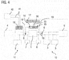
- Figure 4 shows a modification of the embodiment of FIG Figure 3A , wherein the order of the first switch 35 and the diode 36 has been interchanged. Furthermore, in Figure 4 an external charging device 40 is connected to the external charging interface 18, for example a third-party vehicle via a third-party start cable 41.
- FIG. 5 shows a sequence diagram to illustrate an operation of the vehicle electrical system Figure 4 with external start support 40.
- the control unit deactivates the voltage converter 1 when it detects that an external charging device 40 has been connected to the charging interface 18 and then closes the switch 35 of the auxiliary charging circuit 33. This is illustrated by the switching status curve 53, which indicates that the switch 35 is from one open state 53a is switched to a closed state 53b.
- the same potential (U1) 54 is thus present in both sub-networks 11, 12.
- the energy store 3 is charged in the subnetwork 12, so that its voltage 55 rises, which is represented by the curve section 55a.
- This system state is identified in the lower sequence diagram 51 as precharge state 51a.
- the diode state is indicated by the sequence diagram 52. During the precharge phase 51a, the diode is conductive, see curve section 52a.
- an engine start 51b can be started by a electric starter, e.g. B. by the starter generator 5, in the subnet 12, which is supplied by the now charged energy store 3 of the second subnet.
- a electric starter e.g. B. by the starter generator 5, in the subnet 12, which is supplied by the now charged energy store 3 of the second subnet.
- electrical system ripples 55b result, so that the diode 36 briefly becomes conductive 52b due to the drop in the electrical system voltage 55b until the voltage in the subsystem 12 again reaches level (U1).
Landscapes
- Engineering & Computer Science (AREA)
- Power Engineering (AREA)
- Mechanical Engineering (AREA)
- Transportation (AREA)
- Life Sciences & Earth Sciences (AREA)
- Sustainable Development (AREA)
- Sustainable Energy (AREA)
- Charge And Discharge Circuits For Batteries Or The Like (AREA)
Claims (5)
- Réseau de bord (30) pour un véhicule automobile, en particulier pour un véhicule utilitaire, doté
d'un premier sous-réseau (11), aux bornes duquel est appliquée une première tension nominale (U1), comprenant un premier accumulateur d'énergie (2) et une première résistance de charge (4) formée par plusieurs consommateurs ;
d'un deuxième sous-réseau (12), aux bornes duquel est appliquée une deuxième tension nominale (U2), comprenant un deuxième accumulateur d'énergie (3), dans lequel la première tension nominale (U1) est inférieure à la deuxième tension nominale (U2) ;
dans lequel le premier et le deuxième sous-réseau (11, 12) sont couplés l'un à l'autre par un circuit parallèle formé d'un transformateur de tension (1) et d'un dispositif auxiliaire de charge (33), dans lequel le dispositif auxiliaire de charge (33) comprend un élément limiteur de courant non-réglable et au moins un premier commutateur (35) branché en série avec celui-ci,
dans lequel le dispositif auxiliaire de charge (33) comprend au moins un deuxième commutateur, lequel est agencé en série avec le premier commutateur (35) et avec l'élément limiteur de courant,
dans lequel le deuxième commutateur est une diode (36), laquelle bloque dans la direction du premier sous-réseau (11),
caractérisé en ce que
le deuxième sous-réseau comprend un alterno-démarreur (5), et en ce que
le réseau de bord comprend un dispositif de mesure (8, 9) pour saisir la tension dans le premier sous-réseau (11) et pour saisir la tension dans le deuxième sous-réseau (12), dans lequel l'au moins un premier commutateur (35) du dispositif auxiliaire de charge (33) est réalisé de façon à se fermer lorsque la tension dans le deuxième sous-réseau (12) tombe sous une valeur seuil prédéfinie ou lorsqu'un dysfonctionnement du transformateur de tension (1) est observé. - Réseau de bord (30) selon la revendication 1, caractérisé en ce que l'élément limiteur de courant est une résistance ohmique (14).
- Réseau de bord (30) selon la revendication 1 ou 2, caractérisé en ce quea) l'élément limiteur de courant est agencé, par rapport au premier sous-réseau (11), avant l'au moins un premier commutateur (35) et l'au moins un deuxième commutateur ; et/ou en ce queb) le premier sous-réseau (11) comporte une interface de charge (18).
- Réseau de bord (30) selon l'une des revendications précédentes, caractérisé en ce quea) l'alterno-démarreur (5) est une machine électrique, laquelle est réalisée pour fonctionner comme générateur, à savoir pour la récupération, et pour le démarrage d'un moteur à combustion du véhicule automobile ; et/ou en ce queb) l'alterno-démarreur (5) est un alterno-démarreur de vilebrequin ; et/ou en ce quec) le deuxième accumulateur d'énergie (3), de préférence un accumulateur à supercondensateur ou un accumulateur Li-ion, est réalisé pour accumuler la charge électrique produite par l'alterno-démarreur (5) ; et/ou en ce qued) le transformateur de tension (1) raccorde de manière bidirectionnelle le premier sous-réseau (11) au deuxième sous-réseau (12) et est réalisé pour transmettre de l'énergie entre le premier (11) et le deuxième sous-réseau (12) par le biais du transformateur de tension (1) en fonction d'un état de charge du premier accumulateur d'énergie (2) et/ou d'un état de charge du deuxième accumulateur d'énergie (3).
- Véhicule, en particulier véhicule utilitaire, doté d'un réseau de bord (30) selon l'une des revendications précédentes.
Applications Claiming Priority (1)
| Application Number | Priority Date | Filing Date | Title |
|---|---|---|---|
| DE102014008516.3A DE102014008516A1 (de) | 2014-06-07 | 2014-06-07 | Bordnetz für ein Kraftfahrzeug |
Publications (2)
| Publication Number | Publication Date |
|---|---|
| EP2953227A1 EP2953227A1 (fr) | 2015-12-09 |
| EP2953227B1 true EP2953227B1 (fr) | 2019-12-25 |
Family
ID=53039168
Family Applications (1)
| Application Number | Title | Priority Date | Filing Date |
|---|---|---|---|
| EP15001273.0A Active EP2953227B1 (fr) | 2014-06-07 | 2015-04-29 | Réseau de bord pour un véhicule automobile |
Country Status (4)
| Country | Link |
|---|---|
| EP (1) | EP2953227B1 (fr) |
| CN (1) | CN105270295B (fr) |
| DE (1) | DE102014008516A1 (fr) |
| RU (1) | RU2696539C2 (fr) |
Families Citing this family (16)
| Publication number | Priority date | Publication date | Assignee | Title |
|---|---|---|---|---|
| DE102016212543A1 (de) * | 2016-07-11 | 2018-01-11 | Continental Automotive Gmbh | Fahrzeugbordnetze, Ladesystem, Ladestation und Verfahren zur Übertragung von elektrischer Energie |
| EP3276768B1 (fr) * | 2016-07-29 | 2019-04-24 | Ford Global Technologies, LLC | Système de réseau électrique de bord pour véhicules à moteur pourvu d'un convertisseur et d'un consommateur à forte charge |
| EP3403886B1 (fr) * | 2017-05-17 | 2019-12-18 | Mahle International GmbH | Système électrique de véhicule automobile embarqué |
| EP3403885B1 (fr) * | 2017-05-17 | 2019-11-20 | Mahle International GmbH | Système électrique de véhicule automobile embarqué |
| EP3425766B1 (fr) * | 2017-07-03 | 2022-08-24 | Ningbo Geely Automobile Research & Development Co., Ltd. | Module de capaciteur |
| CN107482708B (zh) * | 2017-07-28 | 2021-03-23 | 惠州华阳通用电子有限公司 | 一种车载系统欠压控制方法及装置 |
| DE102017011856A1 (de) | 2017-12-21 | 2019-06-27 | Daimler Ag | Elektrisches Bordnetz für ein Fahrzeug |
| DE102018106306B4 (de) * | 2018-03-19 | 2025-02-06 | Dr. Ing. H.C. F. Porsche Aktiengesellschaft | Fahrzeug mit einem Energiespeicher |
| DE102019201968A1 (de) * | 2018-05-08 | 2019-11-14 | Robert Bosch Gmbh | Batterieeinheit und Verfahren zum Betrieb einer Batterieeinheit |
| DE102018212351A1 (de) * | 2018-07-25 | 2020-01-30 | Robert Bosch Gmbh | Verfahren zur Diagnose eines Schaltmittels in einem Kraftfahrzeug |
| DE102019200034A1 (de) | 2019-01-04 | 2020-07-09 | Robert Bosch Gmbh | Elektrofahrzeug, insbesondere Baumaschine, und Verfahren zum Betrieb eines Elektrofahrzeugs |
| DE102019112706A1 (de) * | 2019-05-15 | 2020-11-19 | Bayerische Motoren Werke Aktiengesellschaft | Verfahren und Vorrichtung zur Energieversorgung eines elektrischen Verbrauchers eines Fahrzeugs |
| DE102019209805A1 (de) * | 2019-07-04 | 2021-01-07 | Robert Bosch Gmbh | Batteriemodul für ein Kraftfahrzeug und Kraftfahrzeug |
| DE102020206953A1 (de) | 2020-06-03 | 2021-12-09 | Vitesco Technologies GmbH | Verfahren zum Erfassen eines Isolationsfehlers in einem Fahrzeugbordnetz |
| EP3930132A1 (fr) * | 2020-06-26 | 2021-12-29 | Volvo Truck Corporation | Interface de connexion entre un réseau haute tension et un réseau basse tension d'un véhicule électrique hybride |
| EP4169760A1 (fr) * | 2021-10-25 | 2023-04-26 | Aptiv Technologies Limited | Circuit de distribution de l'alimentation d'un véhicule et système d'alimentation du véhicule |
Citations (2)
| Publication number | Priority date | Publication date | Assignee | Title |
|---|---|---|---|---|
| DE10160266A1 (de) * | 2001-12-07 | 2003-06-18 | Daimler Chrysler Ag | Verfahren und Anordnung zur Ruhestromversorgung eines Fahrzeugs mit einem Mehrspannungsbordnetz |
| DE102011002264A1 (de) * | 2010-04-27 | 2012-01-26 | Denso Corporation | Leistungsversorgungseinheit mit einer Vielzahl von Akkumulatoren |
Family Cites Families (9)
| Publication number | Priority date | Publication date | Assignee | Title |
|---|---|---|---|---|
| DE10262000B4 (de) | 2002-07-12 | 2006-06-14 | Audi Ag | Bordnetz für ein Kraftfahrzeug |
| DE102005060129A1 (de) | 2005-12-16 | 2007-06-21 | Bayerische Motoren Werke Ag | Verfahren zum Steuern eines Bordnetzes für ein Kraftfahrzeug |
| SE532001C2 (sv) * | 2008-02-04 | 2009-09-22 | Scania Cv Abp | Elsystem för ett motorfordon och förfarande för styrning av en startmotor och en batterifrånskiljare i ett sådant elsystem |
| DE102009041006A1 (de) * | 2009-09-10 | 2011-03-24 | Bayerische Motoren Werke Aktiengesellschaft | Kraftfahrzeug-Bordnetz und Verfahren zum Versorgen eines Kraftfahrzeug-Bordnetzes mit Energie |
| DE102010014104A1 (de) * | 2010-04-07 | 2011-10-13 | Dbk David + Baader Gmbh | Elektrisches Energiebordnetz für ein Kraftfahrzeug |
| DE102012000624A1 (de) * | 2012-01-14 | 2013-07-18 | Volkswagen Aktiengesellschaft | Kraftfahrzeugbordnetz und Verfahren zum Betreiben eines Kraftfahrzeugbordnetzes |
| DE102012017674A1 (de) * | 2012-09-07 | 2014-03-13 | Audi Ag | Kraftfahrzeug mit einem Mehrspannungs-Bordnetz und zugehöriges Verfahren |
| DE102012218471A1 (de) * | 2012-10-10 | 2014-04-10 | Robert Bosch Gmbh | Schaltungsanordnung für ein Bordnetz |
| DE102013206299A1 (de) * | 2013-04-10 | 2014-04-10 | Robert Bosch Gmbh | Mehrspannungsbordnetz für Kraftfahrzeug sowie Verfahren zum Betreiben eines derartigen Mehrspannungsbordnetzes und Mittel zu dessen Implementierung |
-
2014
- 2014-06-07 DE DE102014008516.3A patent/DE102014008516A1/de not_active Withdrawn
-
2015
- 2015-04-29 EP EP15001273.0A patent/EP2953227B1/fr active Active
- 2015-06-03 RU RU2015121192A patent/RU2696539C2/ru active
- 2015-06-08 CN CN201510307714.1A patent/CN105270295B/zh active Active
Patent Citations (2)
| Publication number | Priority date | Publication date | Assignee | Title |
|---|---|---|---|---|
| DE10160266A1 (de) * | 2001-12-07 | 2003-06-18 | Daimler Chrysler Ag | Verfahren und Anordnung zur Ruhestromversorgung eines Fahrzeugs mit einem Mehrspannungsbordnetz |
| DE102011002264A1 (de) * | 2010-04-27 | 2012-01-26 | Denso Corporation | Leistungsversorgungseinheit mit einer Vielzahl von Akkumulatoren |
Also Published As
| Publication number | Publication date |
|---|---|
| RU2696539C2 (ru) | 2019-08-02 |
| RU2015121192A3 (fr) | 2019-01-18 |
| CN105270295B (zh) | 2020-06-12 |
| RU2015121192A (ru) | 2016-12-27 |
| EP2953227A1 (fr) | 2015-12-09 |
| DE102014008516A1 (de) | 2015-12-17 |
| CN105270295A (zh) | 2016-01-27 |
Similar Documents
| Publication | Publication Date | Title |
|---|---|---|
| EP2953227B1 (fr) | Réseau de bord pour un véhicule automobile | |
| DE102007062955B4 (de) | Schaltung zur Spannungsstabilisierung eines Bordnetzes | |
| DE102012222208B4 (de) | Verfahren zum gesteuerten Verbinden mehrerer Bordnetzzweige eines Fahrzeugs, Steuereinheit zur Ausführung des Verfahrens sowie Bordnetz | |
| DE102008054885B4 (de) | Vorrichtung und Verfahren zum Steuern einer Energieversorgung eines Bordnetzes eines Fahrzeugs | |
| EP2721704B1 (fr) | Dispositif et procédé pour coupler des grilles ayant des tensions différentes | |
| DE102016005565B4 (de) | Schaltungsanordnung für eine Zwischenkreiskapazität, Kraftfahrzeug mit einer solchen Schaltungsanordnung sowie Verfahren zum Vorladen einer Zwischenkreiskapazität und Verfahren zum Ausgleichen von Batterieladezuständen parallel geschalteter Batteriemodule | |
| EP3022433B1 (fr) | Disposition d'interrupteur dans un circuit de bord de véhicule à moteur | |
| DE112017000289T5 (de) | Relaisvorrichtung und stromversorgungsvorrichtung | |
| EP2822808B1 (fr) | Réseau de bord pour un véhicule | |
| EP2985189B1 (fr) | Réseau de bord pour un véhicule, en particulier véhicule industriel | |
| DE102010051323B4 (de) | Ladesystem zum Laden einer Batterie eines Fahrzeuges mit einem Zwei-Weg-Laderegler | |
| EP2440432A1 (fr) | Agencement de circuits et procédé de commande pour le maintien de la tension du réseau de bord d'un véhicule | |
| EP2386135A1 (fr) | Réseau de bord pour véhicule automobile équipé d'un système arrêt-démarrage | |
| WO2011121035A1 (fr) | Réseau de bord pour un véhicule ainsi que dispositif de commande pour un réseau de bord | |
| DE102017210611A1 (de) | Elektrische Energieliefervorrichtung mit einer Stromschienenmatrix sowie Verfahren zum Betreiben der Energieliefervorrichtung | |
| EP2840253B1 (fr) | Réseau de bord pour un véhicule automobile et véhicule avec un tel réseau de bord | |
| WO2013113585A2 (fr) | Procédé d'équilibrage de charge d'éléments de batterie, système de batterie et véhicule automobile équipé d'un tel système de batterie | |
| DE102018102676B4 (de) | Elektronisch gesteuerte Stromschaltvorrichtung | |
| EP2582009A1 (fr) | Système de stockage d'énergie avec algorithme de réglage implémenté et procédé de commande de l'état de chargement de ses éléments | |
| DE102013009991A1 (de) | Fremdstartfähige Integration einer Batterie in ein Kraftfahrzeug-Bordnetz | |
| DE102015208568B4 (de) | Bordnetz-Schaltmodul, Bordnetzunterstützungseinrichtung und Bordnetzzweig | |
| DE102013221113A1 (de) | Elektrische Energiespeichervorrichtung | |
| DE102012009563A1 (de) | Schaltungsanordnung mit einem Energiespeicher | |
| DE102013017162A1 (de) | Schalteranordnung in Kraftfahrzeugbordnetz | |
| DE102013018009A1 (de) | Fahrzeugbatterie und Fahrzeugbatteriepolklemme sowie System und Verfahren für eine Fahrzeugbatterie |
Legal Events
| Date | Code | Title | Description |
|---|---|---|---|
| PUAI | Public reference made under article 153(3) epc to a published international application that has entered the european phase |
Free format text: ORIGINAL CODE: 0009012 |
|
| AK | Designated contracting states |
Kind code of ref document: A1 Designated state(s): AL AT BE BG CH CY CZ DE DK EE ES FI FR GB GR HR HU IE IS IT LI LT LU LV MC MK MT NL NO PL PT RO RS SE SI SK SM TR |
|
| AX | Request for extension of the european patent |
Extension state: BA ME |
|
| 17P | Request for examination filed |
Effective date: 20160606 |
|
| STAA | Information on the status of an ep patent application or granted ep patent |
Free format text: STATUS: EXAMINATION IS IN PROGRESS |
|
| 17Q | First examination report despatched |
Effective date: 20180104 |
|
| RAP1 | Party data changed (applicant data changed or rights of an application transferred) |
Owner name: MAN TRUCK & BUS SE |
|
| GRAP | Despatch of communication of intention to grant a patent |
Free format text: ORIGINAL CODE: EPIDOSNIGR1 |
|
| STAA | Information on the status of an ep patent application or granted ep patent |
Free format text: STATUS: GRANT OF PATENT IS INTENDED |
|
| RIC1 | Information provided on ipc code assigned before grant |
Ipc: H02J 7/34 20060101ALN20190712BHEP Ipc: H02J 7/00 20060101ALI20190712BHEP Ipc: B60R 16/03 20060101ALI20190712BHEP Ipc: H02J 1/08 20060101AFI20190712BHEP Ipc: H02J 7/14 20060101ALN20190712BHEP Ipc: H02J 1/00 20060101ALN20190712BHEP |
|
| INTG | Intention to grant announced |
Effective date: 20190819 |
|
| GRAS | Grant fee paid |
Free format text: ORIGINAL CODE: EPIDOSNIGR3 |
|
| GRAA | (expected) grant |
Free format text: ORIGINAL CODE: 0009210 |
|
| STAA | Information on the status of an ep patent application or granted ep patent |
Free format text: STATUS: THE PATENT HAS BEEN GRANTED |
|
| AK | Designated contracting states |
Kind code of ref document: B1 Designated state(s): AL AT BE BG CH CY CZ DE DK EE ES FI FR GB GR HR HU IE IS IT LI LT LU LV MC MK MT NL NO PL PT RO RS SE SI SK SM TR |
|
| REG | Reference to a national code |
Ref country code: GB Ref legal event code: FG4D Free format text: NOT ENGLISH |
|
| REG | Reference to a national code |
Ref country code: CH Ref legal event code: EP |
|
| REG | Reference to a national code |
Ref country code: AT Ref legal event code: REF Ref document number: 1218186 Country of ref document: AT Kind code of ref document: T Effective date: 20200115 |
|
| REG | Reference to a national code |
Ref country code: DE Ref legal event code: R096 Ref document number: 502015011289 Country of ref document: DE |
|
| REG | Reference to a national code |
Ref country code: IE Ref legal event code: FG4D Free format text: LANGUAGE OF EP DOCUMENT: GERMAN |
|
| REG | Reference to a national code |
Ref country code: SE Ref legal event code: TRGR |
|
| REG | Reference to a national code |
Ref country code: NL Ref legal event code: FP |
|
| PG25 | Lapsed in a contracting state [announced via postgrant information from national office to epo] |
Ref country code: FI Free format text: LAPSE BECAUSE OF FAILURE TO SUBMIT A TRANSLATION OF THE DESCRIPTION OR TO PAY THE FEE WITHIN THE PRESCRIBED TIME-LIMIT Effective date: 20191225 Ref country code: BG Free format text: LAPSE BECAUSE OF FAILURE TO SUBMIT A TRANSLATION OF THE DESCRIPTION OR TO PAY THE FEE WITHIN THE PRESCRIBED TIME-LIMIT Effective date: 20200325 Ref country code: LV Free format text: LAPSE BECAUSE OF FAILURE TO SUBMIT A TRANSLATION OF THE DESCRIPTION OR TO PAY THE FEE WITHIN THE PRESCRIBED TIME-LIMIT Effective date: 20191225 Ref country code: NO Free format text: LAPSE BECAUSE OF FAILURE TO SUBMIT A TRANSLATION OF THE DESCRIPTION OR TO PAY THE FEE WITHIN THE PRESCRIBED TIME-LIMIT Effective date: 20200325 Ref country code: GR Free format text: LAPSE BECAUSE OF FAILURE TO SUBMIT A TRANSLATION OF THE DESCRIPTION OR TO PAY THE FEE WITHIN THE PRESCRIBED TIME-LIMIT Effective date: 20200326 Ref country code: LT Free format text: LAPSE BECAUSE OF FAILURE TO SUBMIT A TRANSLATION OF THE DESCRIPTION OR TO PAY THE FEE WITHIN THE PRESCRIBED TIME-LIMIT Effective date: 20191225 |
|
| REG | Reference to a national code |
Ref country code: LT Ref legal event code: MG4D |
|
| PG25 | Lapsed in a contracting state [announced via postgrant information from national office to epo] |
Ref country code: RS Free format text: LAPSE BECAUSE OF FAILURE TO SUBMIT A TRANSLATION OF THE DESCRIPTION OR TO PAY THE FEE WITHIN THE PRESCRIBED TIME-LIMIT Effective date: 20191225 Ref country code: HR Free format text: LAPSE BECAUSE OF FAILURE TO SUBMIT A TRANSLATION OF THE DESCRIPTION OR TO PAY THE FEE WITHIN THE PRESCRIBED TIME-LIMIT Effective date: 20191225 |
|
| PG25 | Lapsed in a contracting state [announced via postgrant information from national office to epo] |
Ref country code: AL Free format text: LAPSE BECAUSE OF FAILURE TO SUBMIT A TRANSLATION OF THE DESCRIPTION OR TO PAY THE FEE WITHIN THE PRESCRIBED TIME-LIMIT Effective date: 20191225 |
|
| PG25 | Lapsed in a contracting state [announced via postgrant information from national office to epo] |
Ref country code: EE Free format text: LAPSE BECAUSE OF FAILURE TO SUBMIT A TRANSLATION OF THE DESCRIPTION OR TO PAY THE FEE WITHIN THE PRESCRIBED TIME-LIMIT Effective date: 20191225 Ref country code: CZ Free format text: LAPSE BECAUSE OF FAILURE TO SUBMIT A TRANSLATION OF THE DESCRIPTION OR TO PAY THE FEE WITHIN THE PRESCRIBED TIME-LIMIT Effective date: 20191225 Ref country code: RO Free format text: LAPSE BECAUSE OF FAILURE TO SUBMIT A TRANSLATION OF THE DESCRIPTION OR TO PAY THE FEE WITHIN THE PRESCRIBED TIME-LIMIT Effective date: 20191225 Ref country code: PT Free format text: LAPSE BECAUSE OF FAILURE TO SUBMIT A TRANSLATION OF THE DESCRIPTION OR TO PAY THE FEE WITHIN THE PRESCRIBED TIME-LIMIT Effective date: 20200520 |
|
| PG25 | Lapsed in a contracting state [announced via postgrant information from national office to epo] |
Ref country code: SK Free format text: LAPSE BECAUSE OF FAILURE TO SUBMIT A TRANSLATION OF THE DESCRIPTION OR TO PAY THE FEE WITHIN THE PRESCRIBED TIME-LIMIT Effective date: 20191225 Ref country code: IS Free format text: LAPSE BECAUSE OF FAILURE TO SUBMIT A TRANSLATION OF THE DESCRIPTION OR TO PAY THE FEE WITHIN THE PRESCRIBED TIME-LIMIT Effective date: 20200425 Ref country code: SM Free format text: LAPSE BECAUSE OF FAILURE TO SUBMIT A TRANSLATION OF THE DESCRIPTION OR TO PAY THE FEE WITHIN THE PRESCRIBED TIME-LIMIT Effective date: 20191225 |
|
| REG | Reference to a national code |
Ref country code: DE Ref legal event code: R097 Ref document number: 502015011289 Country of ref document: DE |
|
| PG25 | Lapsed in a contracting state [announced via postgrant information from national office to epo] |
Ref country code: DK Free format text: LAPSE BECAUSE OF FAILURE TO SUBMIT A TRANSLATION OF THE DESCRIPTION OR TO PAY THE FEE WITHIN THE PRESCRIBED TIME-LIMIT Effective date: 20191225 Ref country code: ES Free format text: LAPSE BECAUSE OF FAILURE TO SUBMIT A TRANSLATION OF THE DESCRIPTION OR TO PAY THE FEE WITHIN THE PRESCRIBED TIME-LIMIT Effective date: 20191225 |
|
| PLBE | No opposition filed within time limit |
Free format text: ORIGINAL CODE: 0009261 |
|
| STAA | Information on the status of an ep patent application or granted ep patent |
Free format text: STATUS: NO OPPOSITION FILED WITHIN TIME LIMIT |
|
| PG25 | Lapsed in a contracting state [announced via postgrant information from national office to epo] |
Ref country code: MC Free format text: LAPSE BECAUSE OF FAILURE TO SUBMIT A TRANSLATION OF THE DESCRIPTION OR TO PAY THE FEE WITHIN THE PRESCRIBED TIME-LIMIT Effective date: 20191225 Ref country code: SI Free format text: LAPSE BECAUSE OF FAILURE TO SUBMIT A TRANSLATION OF THE DESCRIPTION OR TO PAY THE FEE WITHIN THE PRESCRIBED TIME-LIMIT Effective date: 20191225 |
|
| REG | Reference to a national code |
Ref country code: CH Ref legal event code: PL |
|
| 26N | No opposition filed |
Effective date: 20200928 |
|
| PG25 | Lapsed in a contracting state [announced via postgrant information from national office to epo] |
Ref country code: LI Free format text: LAPSE BECAUSE OF NON-PAYMENT OF DUE FEES Effective date: 20200430 Ref country code: CH Free format text: LAPSE BECAUSE OF NON-PAYMENT OF DUE FEES Effective date: 20200430 Ref country code: LU Free format text: LAPSE BECAUSE OF NON-PAYMENT OF DUE FEES Effective date: 20200429 |
|
| REG | Reference to a national code |
Ref country code: BE Ref legal event code: MM Effective date: 20200430 |
|
| PG25 | Lapsed in a contracting state [announced via postgrant information from national office to epo] |
Ref country code: BE Free format text: LAPSE BECAUSE OF NON-PAYMENT OF DUE FEES Effective date: 20200430 Ref country code: PL Free format text: LAPSE BECAUSE OF FAILURE TO SUBMIT A TRANSLATION OF THE DESCRIPTION OR TO PAY THE FEE WITHIN THE PRESCRIBED TIME-LIMIT Effective date: 20191225 |
|
| GBPC | Gb: european patent ceased through non-payment of renewal fee |
Effective date: 20200429 |
|
| PG25 | Lapsed in a contracting state [announced via postgrant information from national office to epo] |
Ref country code: GB Free format text: LAPSE BECAUSE OF NON-PAYMENT OF DUE FEES Effective date: 20200429 Ref country code: IE Free format text: LAPSE BECAUSE OF NON-PAYMENT OF DUE FEES Effective date: 20200429 |
|
| REG | Reference to a national code |
Ref country code: AT Ref legal event code: MM01 Ref document number: 1218186 Country of ref document: AT Kind code of ref document: T Effective date: 20200429 |
|
| PG25 | Lapsed in a contracting state [announced via postgrant information from national office to epo] |
Ref country code: AT Free format text: LAPSE BECAUSE OF NON-PAYMENT OF DUE FEES Effective date: 20200429 |
|
| PG25 | Lapsed in a contracting state [announced via postgrant information from national office to epo] |
Ref country code: TR Free format text: LAPSE BECAUSE OF FAILURE TO SUBMIT A TRANSLATION OF THE DESCRIPTION OR TO PAY THE FEE WITHIN THE PRESCRIBED TIME-LIMIT Effective date: 20191225 Ref country code: MT Free format text: LAPSE BECAUSE OF FAILURE TO SUBMIT A TRANSLATION OF THE DESCRIPTION OR TO PAY THE FEE WITHIN THE PRESCRIBED TIME-LIMIT Effective date: 20191225 Ref country code: CY Free format text: LAPSE BECAUSE OF FAILURE TO SUBMIT A TRANSLATION OF THE DESCRIPTION OR TO PAY THE FEE WITHIN THE PRESCRIBED TIME-LIMIT Effective date: 20191225 |
|
| PG25 | Lapsed in a contracting state [announced via postgrant information from national office to epo] |
Ref country code: MK Free format text: LAPSE BECAUSE OF FAILURE TO SUBMIT A TRANSLATION OF THE DESCRIPTION OR TO PAY THE FEE WITHIN THE PRESCRIBED TIME-LIMIT Effective date: 20191225 |
|
| PGFP | Annual fee paid to national office [announced via postgrant information from national office to epo] |
Ref country code: NL Payment date: 20250424 Year of fee payment: 11 |
|
| PGFP | Annual fee paid to national office [announced via postgrant information from national office to epo] |
Ref country code: DE Payment date: 20250428 Year of fee payment: 11 |
|
| PGFP | Annual fee paid to national office [announced via postgrant information from national office to epo] |
Ref country code: IT Payment date: 20250422 Year of fee payment: 11 |
|
| PGFP | Annual fee paid to national office [announced via postgrant information from national office to epo] |
Ref country code: FR Payment date: 20250424 Year of fee payment: 11 |
|
| PGFP | Annual fee paid to national office [announced via postgrant information from national office to epo] |
Ref country code: SE Payment date: 20250424 Year of fee payment: 11 |