EP2953239B1 - Resonator mit rauschunterdrückung - Google Patents
Resonator mit rauschunterdrückung Download PDFInfo
- Publication number
- EP2953239B1 EP2953239B1 EP14745889.7A EP14745889A EP2953239B1 EP 2953239 B1 EP2953239 B1 EP 2953239B1 EP 14745889 A EP14745889 A EP 14745889A EP 2953239 B1 EP2953239 B1 EP 2953239B1
- Authority
- EP
- European Patent Office
- Prior art keywords
- resonator
- noise cancellation
- noise
- frequency
- main
- Prior art date
- Legal status (The legal status is an assumption and is not a legal conclusion. Google has not performed a legal analysis and makes no representation as to the accuracy of the status listed.)
- Not-in-force
Links
Images



Classifications
-
- H—ELECTRICITY
- H02—GENERATION; CONVERSION OR DISTRIBUTION OF ELECTRIC POWER
- H02J—ELECTRIC POWER NETWORKS; CIRCUIT ARRANGEMENTS OR SYSTEMS FOR SUPPLYING OR DISTRIBUTING ELECTRIC POWER; SYSTEMS FOR STORING ELECTRIC ENERGY
- H02J50/00—Circuit arrangements or systems for wireless supply or distribution of electric power
- H02J50/10—Circuit arrangements or systems for wireless supply or distribution of electric power using inductive coupling
- H02J50/12—Circuit arrangements or systems for wireless supply or distribution of electric power using inductive coupling of the resonant type
-
- H—ELECTRICITY
- H01—ELECTRIC ELEMENTS
- H01F—MAGNETS; INDUCTANCES; TRANSFORMERS; SELECTION OF MATERIALS FOR THEIR MAGNETIC PROPERTIES
- H01F38/00—Adaptations of transformers or inductances for specific applications or functions
- H01F38/14—Inductive couplings
-
- H—ELECTRICITY
- H02—GENERATION; CONVERSION OR DISTRIBUTION OF ELECTRIC POWER
- H02J—ELECTRIC POWER NETWORKS; CIRCUIT ARRANGEMENTS OR SYSTEMS FOR SUPPLYING OR DISTRIBUTING ELECTRIC POWER; SYSTEMS FOR STORING ELECTRIC ENERGY
- H02J50/00—Circuit arrangements or systems for wireless supply or distribution of electric power
- H02J50/10—Circuit arrangements or systems for wireless supply or distribution of electric power using inductive coupling
-
- H—ELECTRICITY
- H02—GENERATION; CONVERSION OR DISTRIBUTION OF ELECTRIC POWER
- H02J—ELECTRIC POWER NETWORKS; CIRCUIT ARRANGEMENTS OR SYSTEMS FOR SUPPLYING OR DISTRIBUTING ELECTRIC POWER; SYSTEMS FOR STORING ELECTRIC ENERGY
- H02J50/00—Circuit arrangements or systems for wireless supply or distribution of electric power
- H02J50/70—Circuit arrangements or systems for wireless supply or distribution of electric power involving the reduction of electric, magnetic or electromagnetic leakage fields
-
- H—ELECTRICITY
- H03—ELECTRONIC CIRCUITRY
- H03H—IMPEDANCE NETWORKS, e.g. RESONANT CIRCUITS; RESONATORS
- H03H7/00—Multiple-port networks comprising only passive electrical elements as network components
- H03H7/01—Frequency selective two-port networks
-
- H—ELECTRICITY
- H01—ELECTRIC ELEMENTS
- H01F—MAGNETS; INDUCTANCES; TRANSFORMERS; SELECTION OF MATERIALS FOR THEIR MAGNETIC PROPERTIES
- H01F27/00—Details of transformers or inductances, in general
- H01F27/34—Special means for preventing or reducing unwanted electric or magnetic effects, e.g. no-load losses, reactive currents, harmonics, oscillations, leakage fields
- H01F27/38—Auxiliary core members; Auxiliary coils or windings
-
- H—ELECTRICITY
- H03—ELECTRONIC CIRCUITRY
- H03H—IMPEDANCE NETWORKS, e.g. RESONANT CIRCUITS; RESONATORS
- H03H7/00—Multiple-port networks comprising only passive electrical elements as network components
- H03H7/01—Frequency selective two-port networks
- H03H2007/013—Notch or bandstop filters
-
- H—ELECTRICITY
- H03—ELECTRONIC CIRCUITRY
- H03H—IMPEDANCE NETWORKS, e.g. RESONANT CIRCUITS; RESONATORS
- H03H7/00—Multiple-port networks comprising only passive electrical elements as network components
- H03H7/01—Frequency selective two-port networks
- H03H7/09—Filters comprising mutual inductance
Definitions
- the present invention relates to a noise cancellation resonator that is suitably used to reduce noise emitted from a wireless power transmission system that uses a magnetic resonance antenna of a magnetic resonance method.
- the resonance frequency of a power transmission-side antenna is equal to the resonance frequency of a power reception-side antenna. Accordingly, the energy is transmitted from the power transmission-side antenna to the power reception-side antenna in an efficient manner.
- One of the major features is the power transmission distance that can be set to between several tens of centimeters and several meters.
- a power reception-side antenna may be mounted in a bottom portion of a vehicle, and power may be supplied to the power reception-side antenna from a power transmission-side antenna that is buried in the ground.
- the power transmission-side antenna it is difficult for the power transmission-side antenna to be completely and electromagnetically coupled to the power reception-side antenna.
- Some noise would emerge as the noise is emitted from the antennas, possibly leading to a rise in the temperature of the metal used in the bottom portion of the vehicle body and the like.
- Patent Document 2 JP2010-87024A discloses a resonant circuit including a conductor, which is provided near a source of noise in such a way as to have a looped closed path, and a capacitor, which is electrically connected to the closed path.
- Document US2011/193417 discloses a noise cancellation resonator provided in a wireless energy transmitting system comprising a main resonator as a power transmitter resonator and a sub-resonator as a power receiver resonator adapted to receive power from the power transmitter resonator, wherein the noise cancellation resonator is located near the power transmitter resonator, the noise cancellation resonator comprising: a noise cancellation resonator coil with an inductance component; and a noise cancellation resonator capacitor with a capacitance component.
- the resonance frequency of a noise-cancelling LC resonator is set equal to the frequency of the source of noise that should be canceled, in order to increase the effect of noise reduction.
- the problem is that, even if the resonance frequency of the noise cancellation resonator is set equal to the frequency of the noise source, this setting may not be enough to reduce noise significantly, particularly as a measure to deal with noise in the wireless power transmission system that uses the magnetic resonance antenna of the magnetic resonance method.
- a noise cancellation resonator provided in a wireless energy transmitting system comprising a main resonator as a power transmitter resonator and a sub-resonator as a power receiver resonator adapted to receive power from the power transmitter resonator, wherein the noise cancellation resonator is located near the power transmitter resonator, the noise cancellation resonator comprises a noise cancellation resonator coil with an inductance component of L n ; and a noise cancellation resonator capacitor with a capacitance component of Cn, wherein, in use, the noise cancellation resonator coil is coupled to a main resonator coil of the main resonator, wherein the noise cancellation resonator does not contribute to the transmission of power to the sub-resonator, and the noise cancellation resonator has a resonance frequency that is calculated by adding a shift frequency that is determined based on a degree of coupling between a main resonator coil and the noise cancellation reson
- the noise cancellation resonator of the present invention is characterized in that the predetermined frequency is a frequency of a fundamental wave of the electromagnetic field generated by the main resonator.
- the noise cancellation resonator of the present invention is characterized in that the predetermined frequency is a frequency of a higher harmonic wave of the electromagnetic field generated by the main resonator.
- the noise cancellation resonator of the present invention is characterized in that the higher harmonic wave is an odd-multiple wave.
- the noise cancellation resonator of the present invention is characterized in that the higher harmonic wave is an even-multiple wave.
- the noise cancellation resonator of the present invention is characterized in that the main resonator is an antenna that is used to transmit power.
- the noise cancellation resonator of the present invention is characterized in that a Q-value is 50 or more.
- the noise cancelation resonator of the present invention is characterized by having a resonance frequency that is calculated by adding a shift frequency, which is determined based on the degree of coupling between the main resonator coil and the noise cancellation resonator coil, to a predetermined frequency of an electromagnetic field generated by the main resonator that is a source of noise and includes the main resonator coil. Therefore, the noise cancellation resonator of the present invention is highly effective in reducing noise, particularly as a measure to deal with noise in the wireless power transmission system that uses the magnetic resonance antenna of the magnetic resonance method.
- a noise cancellation resonator 300 of the present invention is particularly suitable for dealing with noise in a wireless power transmission system that uses a magnetic resonance antenna of a magnetic resonance method.
- the present invention is not limited to such noise sources as the above power transmission system.
- the present invention can improve the effect of noise reduction for various noise sources.
- FIG. 1 is a diagram for explaining the coupling between the noise cancellation resonator 300 and a main resonator 100, which is a source of noise, according to an embodiment of the present invention.
- the main resonator 100 is used as a power transmission antenna of the power transmission system.
- the main resonator 100 generates an electromagnetic field of a predetermined fundamental frequency. It is expected that the main resonator 100 will transmit power to a power reception sub-resonator, not shown, by using the magnetic resonance method.
- the main resonator 100 includes a main resonator coil 110 with an inductance component of L 1 , and a main resonator capacitor 120 with a capacitance component of C 1 , in such a way that the main resonator coil 110 and the main resonator capacitor 120 are connected in series.
- the noise cancellation resonator 300 includes a noise cancellation resonator coil 310 with an inductance component of L n , and a noise cancellation resonator capacitor 320 with a capacitance component of C n , in such a way that the noise cancellation resonator coil 310 and the noise cancellation resonator capacitor 320 are connected in series.
- the noise cancellation resonator 300 does not contribute to the transmission of power to the sub-resonator. It is expected that the noise cancellation resonator 300 will cancel electromagnetic fields (noise) that leak from the main resonator 100.
- the mutual inductance between the main resonator coil 110 and the noise cancellation resonator coil 310 is represented by L m .
- the noise cancellation resonator 300 is actually closed in a terminal section (2). However, in FIG. 1 , the noise cancellation resonator 300 is recognized as a power transmission circuit from the main resonator 100 to the noise cancellation resonator 300. In this manner, the characteristics of the noise cancellation resonator 300 will be described.
- FIG. 2 is a diagram showing frequency dependence of the transmission efficiency of the above power transmission circuit of FIG. 1 , with a diagram of frequency dependence and noise emissivity superimposed thereon.
- the horizontal axis represents frequency; S21 on the vertical axis represents the power that passes through the terminal (2) at a time when a signal is input through terminal (1).
- the resonance frequency of the noise cancellation resonator 300 is represented by f o .
- the main resonator coil 110 of the main resonator 100 is coupled to the noise cancellation resonator coil 310 of the noise cancellation resonator 300 under a magnetic wall condition.
- the main resonator coil 110 of the main resonator 100 is coupled to the noise cancellation resonator coil 310 of the noise cancellation resonator 300 under an electric wall condition.
- FIG. 3 is a schematic diagram showing the state of current and electric field at the first extreme-value frequency (magnetic wall condition coupling frequency).
- the phase of current flowing through the main resonator coil 110 is substantially equal to the phase of current flowing through the noise cancellation resonator coil 310.
- a position where magnetic field vectors are aligned is near a central portion of the main resonator coil 110 or noise cancellation resonator coil 310.
- a magnetic wall has emerged in such a way that the direction of magnetic field is perpendicular with respect to the symmetry plane between the main resonator coil 110 and the noise cancellation resonator coil 310.
- FIG. 4 is a schematic diagram showing the state of current and electric field at the second extreme-value frequency (electric wall condition coupling frequency).
- the phase of current flowing through the main resonator coil 110 is almost opposite to the phase of current flowing through the noise cancellation resonator coil 310.
- a position where magnetic field vectors are aligned is near the symmetry plane of the main resonator coil 110 or noise cancellation resonator coil 310.
- an electric wall has emerged in such a way that the direction of magnetic field is horizontal with respect to the symmetry plane between the main resonator coil 110 and the noise cancellation resonator coil 310.
- a magnetic field from the main resonator coil 110 and a magnetic field from the noise cancellation resonator 300 exclude each other at the symmetry plane.
- the resonance frequency f c of the noise cancellation resonator 300 is set in such a way that the frequency of electromagnetic field (noise) emitted from the main resonator 100 becomes equal to the first extreme-value frequency f m (magnetic wall condition coupling frequency).
- the resonance frequency f c of the noise cancellation resonator 300 is set to a resonance frequency that is calculated by adding a shift frequency f s , which is determined based on the degree of coupling (K) between the main resonator coil 110 and the noise cancellation resonator coil 310, to a predetermined frequency (or f m in the case of the present embodiment) of an electromagnetic field that the main resonator 100 generates.
- the shift frequency f s is determined based on the degree of coupling (K) between the main resonator coil 110 and the noise cancellation resonator coil 310. That is, the shift frequency f s is determined based on the mutual inductance L m between the main resonator coil 110 and the noise cancellation resonator coil 310.
- the noise cancellation resonator 300 When the resonance frequency f c of the noise cancellation resonator 300 is set as described above, the main resonator coil 110 of the main resonator 100, which is a source of noise, is coupled to the noise cancellation resonator coil 310 under the magnetic wall condition. Accordingly, as shown in the frequency characteristics of noise emission of FIG. 2 , the noise cancellation resonator 300 can efficiently cancel the noise emitted from the main resonator 100.
- the effect of noise reduction is high particularly as a measure to deal with noise in the wireless power transmission system that uses the magnetic resonance antenna of the magnetic resonance method.
- the noise cancellation resonator 300 of the present invention is passive with respect to noise. Therefore, it is desirable that the characteristics of the noise cancellation resonator 300 be almost the same as the level of an opposite-phase wave of noise. Moreover, it is desirable that the loss in the noise cancellation resonator 300 be reduced as much as possible. As a result of experiments, it was confirmed that the effect of noise reduction is high when the Q-value of the noise cancellation resonator 300 is 50 or more.
- the frequencies of electromagnetic fields generated from the main resonator 100 which is a source of noise, include not only the fundamental wave but also noise components of higher harmonic waves of the fundamental wave. Accordingly, there is a need to remove the noise components by using the noise cancellation resonator 300.
- the resonance frequency of the noise cancellation resonator 300 should be determined by the following formula (4).
- f 2 n ⁇ 1 2 n ⁇ 1 f m (n: natural number)
- f c 2 n ⁇ 1 f m + f s
- the resonance frequency of the noise cancellation resonator 300 should be determined by the following formula (6).
- f 2 n 2 n f m (n: natural number)
- f c 2 n f m + f s
- the noise cancellation resonator coil 310 of the noise cancellation resonator 300 of the present invention is coupled to the main resonator coil 110 of the main resonator 100 under the magnetic wall condition. In this manner, the noise cancellation resonator coil 310 of the noise cancellation resonator 300 of the present invention is aimed at the noise reduction effect. This principle will be schematically described.
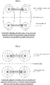
- FIG. 5 is a conceptual diagram for explaining how the effect of noise reduction is improved by the noise cancellation resonator according to the embodiment of the present invention.
- FIG. 5A shows the case where the main resonator coil 110 of the main resonator 100 is coupled to the noise cancellation resonator coil 310 of the noise cancellation resonator 300 under the magnetic wall condition.
- a magnetic field from the main resonator coil 110 is getting into the noise cancellation resonator coil 310.
- a magnetic field that is generated at point X is also expected to get into the noise cancellation resonator coil 310.
- the magnetic field coming from the main resonator coil 110 and the magnetic field getting into the noise cancellation resonator coil 310 cancel each other. In this manner, the effect of noise cancellation will occur.
- FIG. 5B shows the case where the main resonator coil 110 of the main resonator 100 is coupled to the noise cancellation resonator coil 310 of the noise cancellation resonator 300 under the electric wall condition.
- the magnetic field from the main resonator coil 110 and the magnetic field from the noise cancellation resonator 300 exclude each other.
- a magnetic field is expected to emerge in such a way as to get into point X.
- the magnetic field coming from the main resonator coil 110 and the magnetic field coming from the noise cancellation resonator coil 310 boost each other. In this manner, the noise will be amplified.
- FIG. 6 is a schematic diagram showing an example in which a power transmission system that employs a main resonator 100 and a sub-resonator 200 is mounted on a vehicle.
- main resonator 100 and the sub-resonator 200 are a power transmission antenna and power reception antenna of the magnetic resonance method, respectively, and is a power transmission system in which power is wirelessly transmitted from the main resonator 100, which is a power transmission antenna, to the sub-resonator 200, which is a power reception antenna.
- Such a power transmission system is suitably used as a system that is used to charge vehicle-mounted batteries, such as those of electric vehicles (EV) or hybrid electric vehicles (HEV), for example.
- vehicle-mounted batteries such as those of electric vehicles (EV) or hybrid electric vehicles (HEV), for example.
- the power reception antenna is disposed to receive power.
- the system Since power is transmitted to the above vehicle in a non-contact manner, the system is provided in a parking space where the vehicle can be stopped.
- the parking space which is a vehicle charging space
- the power transmission antenna of the power transmission system and the like are buried in the ground.
- a user of the vehicle stops the vehicle in the parking space where the power transmission system of the present embodiment is provided. From the power transmission antenna to the vehicle-mounted power reception antenna, electric energy is transmitted via an electromagnetic field.
- the noise cancellation resonator 300 of the present invention is disposed near the main resonator 100, which is a power transmission antenna. This configuration can reduce the above leakage, and can suppress the effect of the leakage of electromagnetic field on the environment and human body.
- the noise cancelation resonator of the present invention is characterized by having a resonance frequency that is calculated by adding a shift frequency, which is determined based on the degree of coupling between the main resonator coil and the noise cancellation resonator coil, to a predetermined frequency of an electromagnetic field generated by the main resonator that is a source of noise and includes the main resonator coil. Therefore, the noise cancellation resonator of the present invention is highly effective in reducing noise particularly as a measure to deal with noise in the wireless power transmission system that uses the magnetic resonance antenna of the magnetic resonance method.
- the power transmission system of the present invention is preferably used for a wireless power transmission system of a magnetic resonance method to charge vehicles such as electric vehicles (EV) and hybrid electric vehicles (HEV), which have become increasingly popular in recent years.
- EV electric vehicles
- HEV hybrid electric vehicles
- the problem is that, even if the resonance frequency of the noise cancellation resonator is set equal to the frequency of the noise source in order to deal with the noise, this setting may not be enough to reduce noise significantly.
- the noise cancelation resonator of the present invention is characterized by having a resonance frequency that is calculated by adding a shift frequency, which is determined based on the degree of coupling between the main resonator coil and the noise cancellation resonator coil, to a predetermined frequency of an electromagnetic field generated by the main resonator that is a source of noise and includes the main resonator coil. Therefore, the noise cancellation resonator of the present invention is highly effective in reducing noise particularly as a measure to deal with noise in the wireless power transmission system that uses the magnetic resonance antenna of the magnetic resonance method. Therefore, the industrial applicability is very high.
Landscapes
- Engineering & Computer Science (AREA)
- Power Engineering (AREA)
- Computer Networks & Wireless Communication (AREA)
- Physics & Mathematics (AREA)
- Electromagnetism (AREA)
- Electric Propulsion And Braking For Vehicles (AREA)
- Coils Or Transformers For Communication (AREA)
- Filters And Equalizers (AREA)
- Current-Collector Devices For Electrically Propelled Vehicles (AREA)
Claims (8)
- Störsignalentfernungsresonator (300), der in einem drahtlosen Energieübertragungssystem mit einem Hauptresonator (100), als ein Energieübertragungsresonator, und einem Nebenresonator (200), als ein Energieaufnahmeresonator, der eingerichtet ist, um Energie von dem Energieübertragungsresonator aufzunehmen, bereitgestellt ist, wobei sich der Störsignalentfernungsresonator (300) nahe des Energieübertragungsresonators befindet, wobei der Störsignalentfernungsresonator (300) aufweist:eine Störsignalentfernungsresonatorspule (310) mit einer Induktanzkompnente von Ln; und einer Störsignalentfernungsresonatorkapazität (320) mit einer Kapazitätskomponente von Cn,dadurch gekennzeichnet, dassbei Verwendung, die Störsignalentfernungsresonatorspule (310) mit einer Hauptresonatorspule (110) des Hauptresonators (100) gekoppelt ist, wobei der Störsignalentfernungsresonator (300) nicht zu der Übertragung von Energie an den Nebenresonator (200) beiträgt, undder Störsignalentfernungsresonator (300) eine Resonanzfrequenz aufweist, die durch Addieren einer Schaltfrequenz, die basierend auf einem Grad des Koppelns zwischen der Hauptresonatorspule (110) und der Störsignalentfernungsresonatorspule (310) bestimmt wird, zu einer vorbestimmten Frequenz eines durch den Hauptresonator (100) erzeugten elektromagnetischen Feldes, das eine Quelle des Störsignals ist, berechnet wird.
- Störsignalentfernungsresonator (300) gemäß Anspruch 1, dadurch gekennzeichnet, dass
die vorbestimmte Frequenz eine Frequenz einer Grundwelle des durch den Hauptresonator (100) erzeugten elektromagnetischen Feldes ist. - Störsignalentfernungsresonator (300) gemäß Anspruch 1, dadurch gekennzeichnet, dass
die vorbestimmte Frequenz eine Frequenz einer höheren harmonischen Welle des durch den Hauptresonator (100) erzeugten elektromagnetischen Feldes ist. - Störsignalentfernungsresonator (300) gemäß Anspruch 3, dadurch gekennzeichnet, dass
die höhere harmonische Welle eine ungeradzahlige vielfache Welle ist. - Störsignalentfernungsresonator (300) gemäß Anspruch 3, dadurch gekennzeichnet, dass
die höhere harmonische Welle eine geradzahlige vielfache Welle ist. - Störsignalentfernungsresonator (300) gemäß einem der Ansprüche 1 bis 6, dadurch gekennzeichnet, dass
wenn eine gegenseitige Induktanzkomponente zwischen der Hauptresonatorspule (110) und der Störsignalentfernungsresonatorspule (310) durch Lm ausgedrückt wird, die Schaltfrequenz beträgt:
- Störsignalentfernungsresonator (300) gemäß einem der Ansprüche 1 bis 6, dadurch gekennzeichnet, dass
der Hauptresonator (110) eine Antenne ist, die verwendet wird, um Leistung zu übertragen. - Störsignalentfernungsresonator (300) gemäß einem der Ansprüche 1 bis 7, dadurch gekennzeichnet, dass
ein Q-Wert 50 oder mehr beträgt.
Applications Claiming Priority (2)
| Application Number | Priority Date | Filing Date | Title |
|---|---|---|---|
| JP2013016778A JP5967374B2 (ja) | 2013-01-31 | 2013-01-31 | ノイズキャンセル共振器 |
| PCT/JP2014/051974 WO2014119619A1 (ja) | 2013-01-31 | 2014-01-29 | ノイズキャンセル共振器 |
Publications (3)
| Publication Number | Publication Date |
|---|---|
| EP2953239A1 EP2953239A1 (de) | 2015-12-09 |
| EP2953239A4 EP2953239A4 (de) | 2016-09-07 |
| EP2953239B1 true EP2953239B1 (de) | 2018-03-21 |
Family
ID=51262331
Family Applications (1)
| Application Number | Title | Priority Date | Filing Date |
|---|---|---|---|
| EP14745889.7A Not-in-force EP2953239B1 (de) | 2013-01-31 | 2014-01-29 | Resonator mit rauschunterdrückung |
Country Status (5)
| Country | Link |
|---|---|
| US (1) | US9509270B2 (de) |
| EP (1) | EP2953239B1 (de) |
| JP (1) | JP5967374B2 (de) |
| CN (1) | CN104969441B (de) |
| WO (1) | WO2014119619A1 (de) |
Families Citing this family (8)
| Publication number | Priority date | Publication date | Assignee | Title |
|---|---|---|---|---|
| JP6085812B2 (ja) * | 2013-03-29 | 2017-03-01 | 株式会社エクォス・リサーチ | 電力伝送システム |
| JP6040397B2 (ja) * | 2013-03-29 | 2016-12-07 | 株式会社エクォス・リサーチ | 電力伝送システム |
| JP6085813B2 (ja) * | 2013-03-29 | 2017-03-01 | 株式会社エクォス・リサーチ | 電力伝送システム |
| JP6085811B2 (ja) * | 2013-03-29 | 2017-03-01 | 株式会社エクォス・リサーチ | 電力伝送システム |
| JP6142413B2 (ja) | 2013-06-28 | 2017-06-07 | 株式会社エクォス・リサーチ | アンテナコイルユニット |
| WO2016135895A1 (ja) * | 2015-02-25 | 2016-09-01 | 株式会社 東芝 | 共振子及び無線電力伝送装置 |
| JP6538628B2 (ja) * | 2016-09-05 | 2019-07-03 | 株式会社東芝 | フィルタ回路及びワイヤレス電力伝送システム |
| DE102018206812B4 (de) | 2018-05-03 | 2022-06-15 | Audi Ag | Verfahren zur Unterdrückung eines akustischen Signals während eines elektrischen Ladevorgangs eines Fahrzeugs, sowie ein System |
Family Cites Families (26)
| Publication number | Priority date | Publication date | Assignee | Title |
|---|---|---|---|---|
| US7551058B1 (en) * | 2003-12-10 | 2009-06-23 | Advanced Design Consulting Usa, Inc. | Sensor for monitoring environmental parameters in concrete |
| KR101136889B1 (ko) | 2005-07-12 | 2012-04-20 | 메사추세츠 인스티튜트 오브 테크놀로지 | 무선 비-방사성 에너지 전달 |
| AU2007349874B2 (en) * | 2007-03-27 | 2012-02-16 | Massachusetts Institute Of Technology | Wireless energy transfer |
| US7602142B2 (en) * | 2007-04-02 | 2009-10-13 | Visteon Global Technologies, Inc. | System for inductive power transfer |
| JP5335226B2 (ja) * | 2007-11-30 | 2013-11-06 | 三重電子株式会社 | 可動型伝送装置 |
| CN102076518B (zh) * | 2008-07-04 | 2013-06-26 | 村田机械株式会社 | 移动车非接触供电系统及其磁场降低方法 |
| US8432070B2 (en) * | 2008-08-25 | 2013-04-30 | Qualcomm Incorporated | Passive receivers for wireless power transmission |
| US8947041B2 (en) * | 2008-09-02 | 2015-02-03 | Qualcomm Incorporated | Bidirectional wireless power transmission |
| JP2010087024A (ja) * | 2008-09-29 | 2010-04-15 | Nec Corp | 回路基板、回路基板の製造方法および電子機器 |
| JP2010098807A (ja) * | 2008-10-15 | 2010-04-30 | Toyota Motor Corp | 非接触給電システム |
| JP2010183814A (ja) * | 2009-02-09 | 2010-08-19 | Toyota Industries Corp | 非接触電力伝送装置 |
| US8736425B2 (en) * | 2009-10-30 | 2014-05-27 | General Electric Company | Method and system for performance enhancement of resonant sensors |
| WO2011074091A1 (ja) * | 2009-12-17 | 2011-06-23 | トヨタ自動車株式会社 | シールドおよびそれを搭載する車両 |
| JP5077340B2 (ja) * | 2009-12-25 | 2012-11-21 | トヨタ自動車株式会社 | 非接触受電装置およびその製造方法 |
| JP5526833B2 (ja) * | 2010-02-05 | 2014-06-18 | ソニー株式会社 | 無線電力伝送装置 |
| JP5290228B2 (ja) * | 2010-03-30 | 2013-09-18 | 株式会社日本自動車部品総合研究所 | 電圧検出器、異常検出装置、非接触送電装置、非接触受電装置、非接触給電システムおよび車両 |
| ITPI20100042A1 (it) * | 2010-03-31 | 2011-10-01 | Frangerini S R L | Struttura di finestra |
| JP5139469B2 (ja) * | 2010-04-27 | 2013-02-06 | 株式会社日本自動車部品総合研究所 | コイルユニットおよび非接触給電システム |
| EP2632762B1 (de) * | 2010-10-29 | 2017-05-31 | Qualcomm Incorporated(1/3) | Drahtlose energieübertragung über gekoppelte parasitäre resonatoren |
| JP5617829B2 (ja) | 2011-05-31 | 2014-11-05 | 株式会社村田製作所 | コモンモードチョークコイルおよび高周波部品 |
| US9555715B2 (en) * | 2011-12-08 | 2017-01-31 | Institute For Energy Application Technologies Co., Ltd. | Rapid charging power supply system |
| JP2013243431A (ja) * | 2012-05-17 | 2013-12-05 | Equos Research Co Ltd | アンテナコイル |
| US9410823B2 (en) * | 2012-07-13 | 2016-08-09 | Qualcomm Incorporated | Systems, methods, and apparatus for detection of metal objects in a predetermined space |
| JP5988210B2 (ja) * | 2012-08-31 | 2016-09-07 | 株式会社エクォス・リサーチ | 電力伝送システム |
| JP5988211B2 (ja) * | 2012-09-28 | 2016-09-07 | 株式会社エクォス・リサーチ | 電力伝送システム |
| US10324215B2 (en) * | 2014-12-30 | 2019-06-18 | Witricity Corporation | Systems, methods, and apparatus for detecting ferromagnetic foreign objects in a predetermined space |
-
2013
- 2013-01-31 JP JP2013016778A patent/JP5967374B2/ja not_active Expired - Fee Related
-
2014
- 2014-01-29 WO PCT/JP2014/051974 patent/WO2014119619A1/ja not_active Ceased
- 2014-01-29 US US14/436,620 patent/US9509270B2/en not_active Expired - Fee Related
- 2014-01-29 EP EP14745889.7A patent/EP2953239B1/de not_active Not-in-force
- 2014-01-29 CN CN201480006537.7A patent/CN104969441B/zh not_active Expired - Fee Related
Non-Patent Citations (1)
| Title |
|---|
| None * |
Also Published As
| Publication number | Publication date |
|---|---|
| CN104969441A (zh) | 2015-10-07 |
| US9509270B2 (en) | 2016-11-29 |
| JP2014150615A (ja) | 2014-08-21 |
| US20160173051A1 (en) | 2016-06-16 |
| JP5967374B2 (ja) | 2016-08-10 |
| EP2953239A4 (de) | 2016-09-07 |
| WO2014119619A1 (ja) | 2014-08-07 |
| EP2953239A1 (de) | 2015-12-09 |
| CN104969441B (zh) | 2017-09-05 |
Similar Documents
| Publication | Publication Date | Title |
|---|---|---|
| US9509270B2 (en) | Noise cancellation resonator | |
| EP3148030B1 (de) | Kraftübertragungssystem | |
| US8519569B2 (en) | Wireless power supply system and wireless power supply method | |
| US9294154B2 (en) | Enhanced inductive power and data transmission using hyper resonance | |
| US9991047B2 (en) | Antenna coil unit | |
| Jing et al. | Capacity performance of an inductively coupled near field communication system | |
| JP2010074937A (ja) | 非接触受電装置およびそれを備える車両 | |
| JPWO2013054399A1 (ja) | 送電装置、受電装置、および電力伝送システム | |
| US9721722B2 (en) | Power reception device, vehicle including power reception device, and power transfer system | |
| KR102039352B1 (ko) | 무선 전력 송신기 | |
| Amin et al. | Design and simulation of wireless stationary charging system for hybrid electric vehicle using inductive power pad in parking garage | |
| KR20130033837A (ko) | 무선 전력 전송 기기 및 그 방법 | |
| JP2014197928A (ja) | 電力伝送システム | |
| JP2014197932A (ja) | 電力伝送システム | |
| JP6085813B2 (ja) | 電力伝送システム | |
| JP6085811B2 (ja) | 電力伝送システム | |
| KR102040330B1 (ko) | 무선 전력 중계 장치 및 무선 전력 전송 시스템 | |
| JP6085812B2 (ja) | 電力伝送システム | |
| Bartlett et al. | Wireless power for vehicle lightweighting, reducing costs, and improving manufacturing efficiencies: An analysis of resonant capacitive coupling and its ability to reduce vehicle weight and the cost of vehicle manufacturing and maintenance | |
| Sahany et al. | Optimal air-gap of a magnetic resonant inductive link for maximum wireless power transfer | |
| Masuda | Electric field coupling type high power wireless power transfer with leakage electric field strucure | |
| Masuda | A high electric power supply to electric cars using the electric field resonance | |
| US20170187242A1 (en) | Wireless near-field self-resonant impulse receiver |
Legal Events
| Date | Code | Title | Description |
|---|---|---|---|
| PUAI | Public reference made under article 153(3) epc to a published international application that has entered the european phase |
Free format text: ORIGINAL CODE: 0009012 |
|
| 17P | Request for examination filed |
Effective date: 20150429 |
|
| AK | Designated contracting states |
Kind code of ref document: A1 Designated state(s): AL AT BE BG CH CY CZ DE DK EE ES FI FR GB GR HR HU IE IS IT LI LT LU LV MC MK MT NL NO PL PT RO RS SE SI SK SM TR |
|
| AX | Request for extension of the european patent |
Extension state: BA ME |
|
| DAX | Request for extension of the european patent (deleted) | ||
| REG | Reference to a national code |
Ref country code: DE Ref legal event code: R079 Ref document number: 602014022650 Country of ref document: DE Free format text: PREVIOUS MAIN CLASS: H02J0017000000 Ipc: H01F0027000000 |
|
| A4 | Supplementary search report drawn up and despatched |
Effective date: 20160810 |
|
| RIC1 | Information provided on ipc code assigned before grant |
Ipc: H01F 38/14 20060101ALI20160804BHEP Ipc: H01F 27/00 20060101AFI20160804BHEP |
|
| GRAP | Despatch of communication of intention to grant a patent |
Free format text: ORIGINAL CODE: EPIDOSNIGR1 |
|
| STAA | Information on the status of an ep patent application or granted ep patent |
Free format text: STATUS: GRANT OF PATENT IS INTENDED |
|
| INTG | Intention to grant announced |
Effective date: 20171002 |
|
| GRAS | Grant fee paid |
Free format text: ORIGINAL CODE: EPIDOSNIGR3 |
|
| GRAA | (expected) grant |
Free format text: ORIGINAL CODE: 0009210 |
|
| STAA | Information on the status of an ep patent application or granted ep patent |
Free format text: STATUS: THE PATENT HAS BEEN GRANTED |
|
| AK | Designated contracting states |
Kind code of ref document: B1 Designated state(s): AL AT BE BG CH CY CZ DE DK EE ES FI FR GB GR HR HU IE IS IT LI LT LU LV MC MK MT NL NO PL PT RO RS SE SI SK SM TR |
|
| REG | Reference to a national code |
Ref country code: GB Ref legal event code: FG4D |
|
| REG | Reference to a national code |
Ref country code: CH Ref legal event code: EP |
|
| REG | Reference to a national code |
Ref country code: AT Ref legal event code: REF Ref document number: 981920 Country of ref document: AT Kind code of ref document: T Effective date: 20180415 |
|
| REG | Reference to a national code |
Ref country code: IE Ref legal event code: FG4D |
|
| REG | Reference to a national code |
Ref country code: DE Ref legal event code: R096 Ref document number: 602014022650 Country of ref document: DE |
|
| REG | Reference to a national code |
Ref country code: NL Ref legal event code: MP Effective date: 20180321 |
|
| PG25 | Lapsed in a contracting state [announced via postgrant information from national office to epo] |
Ref country code: HR Free format text: LAPSE BECAUSE OF FAILURE TO SUBMIT A TRANSLATION OF THE DESCRIPTION OR TO PAY THE FEE WITHIN THE PRESCRIBED TIME-LIMIT Effective date: 20180321 Ref country code: LT Free format text: LAPSE BECAUSE OF FAILURE TO SUBMIT A TRANSLATION OF THE DESCRIPTION OR TO PAY THE FEE WITHIN THE PRESCRIBED TIME-LIMIT Effective date: 20180321 Ref country code: CY Free format text: LAPSE BECAUSE OF FAILURE TO SUBMIT A TRANSLATION OF THE DESCRIPTION OR TO PAY THE FEE WITHIN THE PRESCRIBED TIME-LIMIT Effective date: 20180321 Ref country code: FI Free format text: LAPSE BECAUSE OF FAILURE TO SUBMIT A TRANSLATION OF THE DESCRIPTION OR TO PAY THE FEE WITHIN THE PRESCRIBED TIME-LIMIT Effective date: 20180321 Ref country code: NO Free format text: LAPSE BECAUSE OF FAILURE TO SUBMIT A TRANSLATION OF THE DESCRIPTION OR TO PAY THE FEE WITHIN THE PRESCRIBED TIME-LIMIT Effective date: 20180621 |
|
| REG | Reference to a national code |
Ref country code: LT Ref legal event code: MG4D |
|
| REG | Reference to a national code |
Ref country code: AT Ref legal event code: MK05 Ref document number: 981920 Country of ref document: AT Kind code of ref document: T Effective date: 20180321 |
|
| PG25 | Lapsed in a contracting state [announced via postgrant information from national office to epo] |
Ref country code: SE Free format text: LAPSE BECAUSE OF FAILURE TO SUBMIT A TRANSLATION OF THE DESCRIPTION OR TO PAY THE FEE WITHIN THE PRESCRIBED TIME-LIMIT Effective date: 20180321 Ref country code: RS Free format text: LAPSE BECAUSE OF FAILURE TO SUBMIT A TRANSLATION OF THE DESCRIPTION OR TO PAY THE FEE WITHIN THE PRESCRIBED TIME-LIMIT Effective date: 20180321 Ref country code: BG Free format text: LAPSE BECAUSE OF FAILURE TO SUBMIT A TRANSLATION OF THE DESCRIPTION OR TO PAY THE FEE WITHIN THE PRESCRIBED TIME-LIMIT Effective date: 20180621 Ref country code: LV Free format text: LAPSE BECAUSE OF FAILURE TO SUBMIT A TRANSLATION OF THE DESCRIPTION OR TO PAY THE FEE WITHIN THE PRESCRIBED TIME-LIMIT Effective date: 20180321 Ref country code: GR Free format text: LAPSE BECAUSE OF FAILURE TO SUBMIT A TRANSLATION OF THE DESCRIPTION OR TO PAY THE FEE WITHIN THE PRESCRIBED TIME-LIMIT Effective date: 20180622 |
|
| PG25 | Lapsed in a contracting state [announced via postgrant information from national office to epo] |
Ref country code: AL Free format text: LAPSE BECAUSE OF FAILURE TO SUBMIT A TRANSLATION OF THE DESCRIPTION OR TO PAY THE FEE WITHIN THE PRESCRIBED TIME-LIMIT Effective date: 20180321 Ref country code: RO Free format text: LAPSE BECAUSE OF FAILURE TO SUBMIT A TRANSLATION OF THE DESCRIPTION OR TO PAY THE FEE WITHIN THE PRESCRIBED TIME-LIMIT Effective date: 20180321 Ref country code: NL Free format text: LAPSE BECAUSE OF FAILURE TO SUBMIT A TRANSLATION OF THE DESCRIPTION OR TO PAY THE FEE WITHIN THE PRESCRIBED TIME-LIMIT Effective date: 20180321 Ref country code: PL Free format text: LAPSE BECAUSE OF FAILURE TO SUBMIT A TRANSLATION OF THE DESCRIPTION OR TO PAY THE FEE WITHIN THE PRESCRIBED TIME-LIMIT Effective date: 20180321 Ref country code: ES Free format text: LAPSE BECAUSE OF FAILURE TO SUBMIT A TRANSLATION OF THE DESCRIPTION OR TO PAY THE FEE WITHIN THE PRESCRIBED TIME-LIMIT Effective date: 20180321 Ref country code: EE Free format text: LAPSE BECAUSE OF FAILURE TO SUBMIT A TRANSLATION OF THE DESCRIPTION OR TO PAY THE FEE WITHIN THE PRESCRIBED TIME-LIMIT Effective date: 20180321 |
|
| PG25 | Lapsed in a contracting state [announced via postgrant information from national office to epo] |
Ref country code: SK Free format text: LAPSE BECAUSE OF FAILURE TO SUBMIT A TRANSLATION OF THE DESCRIPTION OR TO PAY THE FEE WITHIN THE PRESCRIBED TIME-LIMIT Effective date: 20180321 Ref country code: AT Free format text: LAPSE BECAUSE OF FAILURE TO SUBMIT A TRANSLATION OF THE DESCRIPTION OR TO PAY THE FEE WITHIN THE PRESCRIBED TIME-LIMIT Effective date: 20180321 Ref country code: SM Free format text: LAPSE BECAUSE OF FAILURE TO SUBMIT A TRANSLATION OF THE DESCRIPTION OR TO PAY THE FEE WITHIN THE PRESCRIBED TIME-LIMIT Effective date: 20180321 Ref country code: CZ Free format text: LAPSE BECAUSE OF FAILURE TO SUBMIT A TRANSLATION OF THE DESCRIPTION OR TO PAY THE FEE WITHIN THE PRESCRIBED TIME-LIMIT Effective date: 20180321 |
|
| PG25 | Lapsed in a contracting state [announced via postgrant information from national office to epo] |
Ref country code: PT Free format text: LAPSE BECAUSE OF FAILURE TO SUBMIT A TRANSLATION OF THE DESCRIPTION OR TO PAY THE FEE WITHIN THE PRESCRIBED TIME-LIMIT Effective date: 20180723 |
|
| REG | Reference to a national code |
Ref country code: DE Ref legal event code: R097 Ref document number: 602014022650 Country of ref document: DE |
|
| PLBE | No opposition filed within time limit |
Free format text: ORIGINAL CODE: 0009261 |
|
| STAA | Information on the status of an ep patent application or granted ep patent |
Free format text: STATUS: NO OPPOSITION FILED WITHIN TIME LIMIT |
|
| PG25 | Lapsed in a contracting state [announced via postgrant information from national office to epo] |
Ref country code: DK Free format text: LAPSE BECAUSE OF FAILURE TO SUBMIT A TRANSLATION OF THE DESCRIPTION OR TO PAY THE FEE WITHIN THE PRESCRIBED TIME-LIMIT Effective date: 20180321 |
|
| 26N | No opposition filed |
Effective date: 20190102 |
|
| PG25 | Lapsed in a contracting state [announced via postgrant information from national office to epo] |
Ref country code: IT Free format text: LAPSE BECAUSE OF FAILURE TO SUBMIT A TRANSLATION OF THE DESCRIPTION OR TO PAY THE FEE WITHIN THE PRESCRIBED TIME-LIMIT Effective date: 20180321 |
|
| PG25 | Lapsed in a contracting state [announced via postgrant information from national office to epo] |
Ref country code: SI Free format text: LAPSE BECAUSE OF FAILURE TO SUBMIT A TRANSLATION OF THE DESCRIPTION OR TO PAY THE FEE WITHIN THE PRESCRIBED TIME-LIMIT Effective date: 20180321 |
|
| PG25 | Lapsed in a contracting state [announced via postgrant information from national office to epo] |
Ref country code: MC Free format text: LAPSE BECAUSE OF FAILURE TO SUBMIT A TRANSLATION OF THE DESCRIPTION OR TO PAY THE FEE WITHIN THE PRESCRIBED TIME-LIMIT Effective date: 20180321 |
|
| REG | Reference to a national code |
Ref country code: CH Ref legal event code: PL |
|
| GBPC | Gb: european patent ceased through non-payment of renewal fee |
Effective date: 20190129 |
|
| PG25 | Lapsed in a contracting state [announced via postgrant information from national office to epo] |
Ref country code: LU Free format text: LAPSE BECAUSE OF NON-PAYMENT OF DUE FEES Effective date: 20190129 |
|
| REG | Reference to a national code |
Ref country code: BE Ref legal event code: MM Effective date: 20190131 |
|
| REG | Reference to a national code |
Ref country code: IE Ref legal event code: MM4A |
|
| PG25 | Lapsed in a contracting state [announced via postgrant information from national office to epo] |
Ref country code: FR Free format text: LAPSE BECAUSE OF NON-PAYMENT OF DUE FEES Effective date: 20190131 |
|
| PG25 | Lapsed in a contracting state [announced via postgrant information from national office to epo] |
Ref country code: BE Free format text: LAPSE BECAUSE OF NON-PAYMENT OF DUE FEES Effective date: 20190131 |
|
| PG25 | Lapsed in a contracting state [announced via postgrant information from national office to epo] |
Ref country code: GB Free format text: LAPSE BECAUSE OF NON-PAYMENT OF DUE FEES Effective date: 20190129 Ref country code: LI Free format text: LAPSE BECAUSE OF NON-PAYMENT OF DUE FEES Effective date: 20190131 Ref country code: CH Free format text: LAPSE BECAUSE OF NON-PAYMENT OF DUE FEES Effective date: 20190131 |
|
| PG25 | Lapsed in a contracting state [announced via postgrant information from national office to epo] |
Ref country code: IE Free format text: LAPSE BECAUSE OF NON-PAYMENT OF DUE FEES Effective date: 20190129 |
|
| PG25 | Lapsed in a contracting state [announced via postgrant information from national office to epo] |
Ref country code: TR Free format text: LAPSE BECAUSE OF FAILURE TO SUBMIT A TRANSLATION OF THE DESCRIPTION OR TO PAY THE FEE WITHIN THE PRESCRIBED TIME-LIMIT Effective date: 20180321 |
|
| PG25 | Lapsed in a contracting state [announced via postgrant information from national office to epo] |
Ref country code: MT Free format text: LAPSE BECAUSE OF NON-PAYMENT OF DUE FEES Effective date: 20190129 |
|
| PG25 | Lapsed in a contracting state [announced via postgrant information from national office to epo] |
Ref country code: IS Free format text: LAPSE BECAUSE OF FAILURE TO SUBMIT A TRANSLATION OF THE DESCRIPTION OR TO PAY THE FEE WITHIN THE PRESCRIBED TIME-LIMIT Effective date: 20180721 |
|
| PG25 | Lapsed in a contracting state [announced via postgrant information from national office to epo] |
Ref country code: HU Free format text: LAPSE BECAUSE OF FAILURE TO SUBMIT A TRANSLATION OF THE DESCRIPTION OR TO PAY THE FEE WITHIN THE PRESCRIBED TIME-LIMIT; INVALID AB INITIO Effective date: 20140129 |
|
| PG25 | Lapsed in a contracting state [announced via postgrant information from national office to epo] |
Ref country code: MK Free format text: LAPSE BECAUSE OF FAILURE TO SUBMIT A TRANSLATION OF THE DESCRIPTION OR TO PAY THE FEE WITHIN THE PRESCRIBED TIME-LIMIT Effective date: 20180321 |
|
| PGFP | Annual fee paid to national office [announced via postgrant information from national office to epo] |
Ref country code: DE Payment date: 20221207 Year of fee payment: 10 |
|
| REG | Reference to a national code |
Ref country code: DE Ref legal event code: R119 Ref document number: 602014022650 Country of ref document: DE |
|
| PG25 | Lapsed in a contracting state [announced via postgrant information from national office to epo] |
Ref country code: DE Free format text: LAPSE BECAUSE OF NON-PAYMENT OF DUE FEES Effective date: 20240801 |
|
| PG25 | Lapsed in a contracting state [announced via postgrant information from national office to epo] |
Ref country code: DE Free format text: LAPSE BECAUSE OF NON-PAYMENT OF DUE FEES Effective date: 20240801 |