EP2953329B1 - Étui en cuir rabattable de téléphone portable et téléphone intelligent - Google Patents
Étui en cuir rabattable de téléphone portable et téléphone intelligent Download PDFInfo
- Publication number
- EP2953329B1 EP2953329B1 EP13873464.5A EP13873464A EP2953329B1 EP 2953329 B1 EP2953329 B1 EP 2953329B1 EP 13873464 A EP13873464 A EP 13873464A EP 2953329 B1 EP2953329 B1 EP 2953329B1
- Authority
- EP
- European Patent Office
- Prior art keywords
- leather cover
- clasping
- disposed
- smart phone
- micro
- Prior art date
- Legal status (The legal status is an assumption and is not a legal conclusion. Google has not performed a legal analysis and makes no representation as to the accuracy of the status listed.)
- Active
Links
Images



Classifications
-
- H—ELECTRICITY
- H04—ELECTRIC COMMUNICATION TECHNIQUE
- H04B—TRANSMISSION
- H04B1/00—Details of transmission systems, not covered by a single one of groups H04B3/00 - H04B13/00; Details of transmission systems not characterised by the medium used for transmission
- H04B1/38—Transceivers, i.e. devices in which transmitter and receiver form a structural unit and in which at least one part is used for functions of transmitting and receiving
- H04B1/3827—Portable transceivers
- H04B1/3888—Arrangements for carrying or protecting transceivers
-
- H—ELECTRICITY
- H04—ELECTRIC COMMUNICATION TECHNIQUE
- H04M—TELEPHONIC COMMUNICATION
- H04M1/00—Substation equipment, e.g. for use by subscribers
- H04M1/02—Constructional features of telephone sets
- H04M1/18—Telephone sets specially adapted for use in ships, mines, or other places exposed to adverse environment
- H04M1/185—Improving the shock resistance of the housing, e.g. by increasing the rigidity
-
- G—PHYSICS
- G06—COMPUTING OR CALCULATING; COUNTING
- G06F—ELECTRIC DIGITAL DATA PROCESSING
- G06F1/00—Details not covered by groups G06F3/00 - G06F13/00 and G06F21/00
- G06F1/16—Constructional details or arrangements
- G06F1/1613—Constructional details or arrangements for portable computers
- G06F1/1626—Constructional details or arrangements for portable computers with a single-body enclosure integrating a flat display, e.g. Personal Digital Assistants [PDAs]
-
- H—ELECTRICITY
- H04—ELECTRIC COMMUNICATION TECHNIQUE
- H04M—TELEPHONIC COMMUNICATION
- H04M1/00—Substation equipment, e.g. for use by subscribers
- H04M1/02—Constructional features of telephone sets
- H04M1/0202—Portable telephone sets, e.g. cordless phones, mobile phones or bar type handsets
-
- H—ELECTRICITY
- H04—ELECTRIC COMMUNICATION TECHNIQUE
- H04M—TELEPHONIC COMMUNICATION
- H04M1/00—Substation equipment, e.g. for use by subscribers
- H04M1/02—Constructional features of telephone sets
- H04M1/0202—Portable telephone sets, e.g. cordless phones, mobile phones or bar type handsets
- H04M1/0279—Improving the user comfort or ergonomics
- H04M1/0283—Improving the user comfort or ergonomics for providing a decorative aspect, e.g. customization of casings, exchangeable faceplate
-
- A—HUMAN NECESSITIES
- A45—HAND OR TRAVELLING ARTICLES
- A45C—PURSES; LUGGAGE; HAND CARRIED BAGS
- A45C11/00—Receptacles for purposes not provided for in groups A45C1/00-A45C9/00
- A45C11/002—Receptacles for purposes not provided for in groups A45C1/00-A45C9/00 for storing portable handheld communication devices, e.g. pagers or smart phones
-
- G—PHYSICS
- G06—COMPUTING OR CALCULATING; COUNTING
- G06F—ELECTRIC DIGITAL DATA PROCESSING
- G06F2200/00—Indexing scheme relating to G06F1/04 - G06F1/32
- G06F2200/16—Indexing scheme relating to G06F1/16 - G06F1/18
- G06F2200/163—Indexing scheme relating to constructional details of the computer
- G06F2200/1634—Integrated protective display lid, e.g. for touch-sensitive display in handheld computer
-
- H—ELECTRICITY
- H04—ELECTRIC COMMUNICATION TECHNIQUE
- H04M—TELEPHONIC COMMUNICATION
- H04M1/00—Substation equipment, e.g. for use by subscribers
- H04M1/02—Constructional features of telephone sets
- H04M1/0202—Portable telephone sets, e.g. cordless phones, mobile phones or bar type handsets
- H04M1/0206—Portable telephones comprising a plurality of mechanically joined movable body parts, e.g. hinged housings
- H04M1/0208—Portable telephones comprising a plurality of mechanically joined movable body parts, e.g. hinged housings characterized by the relative motions of the body parts
- H04M1/0214—Foldable telephones, i.e. with body parts pivoting to an open position around an axis parallel to the plane they define in closed position
-
- H—ELECTRICITY
- H04—ELECTRIC COMMUNICATION TECHNIQUE
- H04M—TELEPHONIC COMMUNICATION
- H04M1/00—Substation equipment, e.g. for use by subscribers
- H04M1/02—Constructional features of telephone sets
- H04M1/23—Construction or mounting of dials or of equivalent devices; Means for facilitating the use thereof
Definitions
- the present invention relates to a protection cover of smart phone case, and more particularly to a leafing leather cover of cellular phone to be easily disassembled and to be conveniently cleaned in the smart phone.
- a conventional leafing leather cover buckled to the front side of the smart phone to protect the touch panel thereof is provided.
- the conventional leafing leather cover is directly welded on the battery covering with plastic material by way of ultrasonic or hot melt technique and the battery covering is then fastened to the smart phone case by way of a buckling element on the battery covering. While using the smart phone, it is difficult to disassemble and assemble and to clean up the conventional leafing leather cover. Further, the constant disassembling and assembling easily damages the buckling element of the battery covering, which results in improperly deforming, over-loosening or over-tightening the buckling element, and even fracturing the buckling element.
- EP1760995A2 filed on August 01, 2006 , describes a portable terminal comprising a main body, a fastening cradle and an exchangeable cover fixed to the cradle.
- Another prior art of application No. CN201270893, filed on August 15, 2008 describes a bar phone screen protecting cover.
- Still another prior art of application No. CN202269549, filed on August 15, 2008 describes a multifunctional mobile phone protection sleeve.
- one objective of the present invention is to provide a leafing leather cover of cellular phone to be easily disassembled and to be conveniently cleaned.
- Another objective of the present invention is to provide a smart phone employing the leafing leather cover of cellular phone to be easily disassembled and conveniently cleaned.
- one embodiment of the present invention sets forth a leafing leather cover of cellular phone comprising: a leather cover, for buckling to a touch panel of a smart phone; wherein the leather cover is connected to a rear shell body of the smart phone by way of a micro-buckling connection portion, a clasping portion is disposed on the micro-buckling connection portion, the clasping portion adapts to the clasping hole in the rear shell body, and the clasping portion is embedded to a clasping ring in the clasping hole; wherein a magnetic strip disposed in the leather cover is attracted to a magnet in a front shell body of the smart phone, and the magnetic strip is disposed in the other side opposite to a connection side of the leather cover; and wherein a recess slot is disposed in an assembly surface of the micro-buckling connection portion and the recess slot is used to fasten a connection side of the leather cover, a side of the recess slot communicates with a lateral surface of the micro-buckling connection portion, and a
- the magnetic strip is embedded to an internal portion of the leather cover.
- a plurality of stationary posts are further disposed on the bottom surface of the recess slot for fastening the leather cover, a first stationary hole are disposed on the connection side of the leather cover to be passed by the stationary posts, a steel sheet is used to tightly press the connection side of the leather cover in the recess slot of the micro-buckling connection portion, and a second stationary hole is disposed in the steel sheet to be passed by the stationary posts.
- connection side of the leather cover further comprises a first notch for preventing an interference with the clasping portion
- steel sheet further comprises a second notch for avoiding the interference with the clasping portion
- a transparent Mylar sheet is covered with the surface of the steel sheet, and a plurality of third notches disposed on the transparent Mylar sheet adapts to the clasping portion to be passed therethrough.
- Still another embodiment of the present invention sets forth a smart phone comprising a cellular phone body and a leafing leather cover which is disposed on a surface of the cellular phone body, and the leafing leather cover of cellular phone comprising a leather cover for buckling to a touch panel of the smart phone; wherein the leather cover is connected to a rear shell body of the smart phone by way of a micro-buckling connection portion, a clasping portion is disposed on the micro-buckling connection portion, a clasping hole disposed in the rear shell body of the cellular phone body adapts to the clasping portion to be passed therethrough, a clasping ring is disposed on an internal side of the rear shell body near the clasping hole, and the clasping portion adapts to the clasping hole in the rear shell body, and the clasping portion is embedded to a clasping ring in the clasping hole.
- a magnetic strip disposed in the leather cover is attracted to a magnet in a front shell body of the smart phone, and the magnetic strip is disposed in the other side opposite to a connection side of the leather cover.
- the magnetic strip is embedded to an internal portion of the leather cover.
- a recess slot is disposed in an assembly surface of the micro-buckling connection portion and the recess slot is used to fasten a connection side of the leather cover, a side of the recess slot communicates with a lateral surface of the micro-buckling connection portion, and a bottom region of the clasping portion is integrally connected to a bottom surface of the recess slot.
- a plurality of stationary posts are further disposed on the bottom surface of the recess slot for fastening the leather cover, a first stationary hole are disposed on the connection side of the leather cover to be passed by the stationary posts, a steel sheet is used to tightly press the connection side of the leather cover in the recess slot of the micro-buckling connection portion, and a second stationary hole is disposed in the steel sheet to be passed by the stationary posts.
- connection side of the leather cover further comprises a first notch for preventing an interference with the clasping portion
- the steel sheet further comprises a second notch for avoiding the interference with the clasping portion
- a transparent Mylar sheet is covered with the surface of the steel sheet, and a plurality of third notches disposed on the transparent Mylar sheet adapts to the clasping portion to be passed therethrough.
- the present invention provides a leafing leather cover of cellular phone and a smart phone using the same.
- the clasping ring clips the clasping portion to connect the leafing leather cover to the smart phone case.
- the leafing leather cover of cellular phone is easily disassembled and to be conveniently cleaned in the smart phone for increasing the life-span of the leafing leather cover and avoiding the damage of the buckling element on the battery cover.
- FIG. 1 it is a schematic view of a leafing leather cover of cellular phone according to one embodiment of the present invention.
- the leafing leather cover of cellular phone includes a leather cover 200 and a micro-buckling connection portion 300.
- a connection side 201 of the leather cover 200 forms a partial extending portion to serve as a bending portion 210 of the leather cover 200.
- the micro-buckling connection portion 300 is disposed on the bending portion 210 for mounting one side of the leather cover 200 on the shell body of the smart phone.
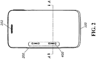
- FIG. 2 it is a schematic front side view of the smart phone according to one embodiment of the present invention.
- the leather cover 200 is fastened to touch panel of the smart phone 100 for protecting the screen of the touch panel from damage.
- a hollow opening 202 is disposed in the upper portion of the leather cover 200 and receives the calls when the leather cover 200 is covered with the smart phone 100 to prevent the finger, cheek or ear from contacting the touch panel, which affects the communication.
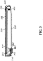
- FIG. 3 is a schematic cross-sectional enlarged view of the smart phone along line A-A according to one embodiment of the present invention.
- the bending portion 210 of the leather cover 200 is connected to the clasping hole 301 of the rear shell body 130 by way of the micro-buckling connection portion 300.
- the micro-buckling connection portion 300 By using the micro-buckling connection portion 300, one side of the leather cover 200 is connected to the shell body of the smart phone case so that the leafing leather cover of cellular phone is easily disassembled and conveniently cleaned.
- the clasping portion is adapted for the clasping hole 301 properly, such as the matching status of the same shape, size and position between the clasping portion and clasping hole 301.
- the clasping portion 350 is disposed on the assembly surface of the micro-buckling connection portion 300.
- the clasping hole 301 disposed in the rear shell body 130 correspondingly adapts to the clasping portion 350 to be passed therethrough.
- a plurality of clasping rings 400 are disposed on the internal side of the rear shell body 130 in form of two opposite concave shapes, as shown by the dashed line in FIG. 2 .
- the clasping rings 400 are used to clasp the opposite recesses of the clasping portion 350 for holding the micro-buckling connection portion 300 when the clasping portion 350 is inserted to the rear shell body 130 correspondingly.
- the clasping portion 350 is embedded to the clasping ring 400 in the clasping hole 301 so that the leather cover 200 is connected to the rear shell body 130 of the smart phone 100 by way of the micro-buckling connection portion 300.
- the leather cover 200 is removed from the smart phone 100, only two square clasping holes 301 remain in the rear shell body 130. Therefore, the leafing leather cover is easily disassembled and the case of smart phone 100 is conveniently cleaned to maintain the leafing leather cover sanitary.
- the clasping rings 400 is fastened to the clasping hole 301 of the rear shell body 130 by way of the strip ribs or posts (not shown) in the internal side of the rear shell body 130.
- a clasping ring lid 500 is disposed around the clasping ring 400 on the rear shell body 130 to prevent the clasping ring 400 from coming off the rear shell body 130.
- an inner magnet 600 is fastened to the front shell body 120 of the smart phone 100 and the magnetic induction region of the inner magnet 600 reaches the external side of the touch panel 110.
- an outer magnet 700 fastened to the leather cover 200 is used to mutually attract the inner magnet 600.
- the outer magnet 700 enters the magnetic induction region of the inner magnet 600.
- a mutual magnetic attraction force between the outer magnet 700 and the inner magnet 600 is generated so that the leafing side of the leather cover 200 is attached to the touch panel 110 to be locked for preventing the leather cover 200 from arbitrarily leafing.
- the outer magnet 700 forms a strip shape to be embedded to the internal portion of the leather cover 200 in order to conveniently clean the leather cover 200.
- the outer magnet 700 is disposed in a free side opposite to the connection side 201 of the leather cover 200, i.e. the other side opposite to the connection side 201.
- the outer magnet 700 is disposed in the lower and middle position of the leather cover 200 for conveniently leafing the leather cover 200 by way of fingers.
- FIG. 4 is a schematic three-dimensional exploded view of a micro-buckling connection portion of the leafing leather cover of cellular phone according to one embodiment of the present invention.
- a recess slot 310 is disposed in the assembly surface of the micro-buckling connection portion 300 and the recess slot 310 is used to fasten the bending portion 210 of the leather cover 200 to reduce the thickness of the micro-buckling connection portion 300.
- One side of the recess slot 310 communicates with the lateral surface of the micro-buckling connection portion 300 for conveniently containing the bending portion 210 of the leather cover 200.
- the bottom of clasping portion 350 is integrally connected to the bottom surface of the recess slot 310.
- FIG. 5 is a partially schematic exploded view of the leafing leather cover of cellular phone according to one embodiment of the present invention.
- a first stationary hole (not shown), which the stationary posts 340 pass through, are disposed on the bending portion 210 of the leather cover 200.
- a steel sheet 800 is used to tightly press the bending portion 210 of the leather cover 200 in the recess slot 310 of the micro-buckling connection portion 300.
- the second stationary holes 840 are disposed in the steel sheet 800 to be passed by the stationary posts 340.
- the buckling rib 320 is adapted to the steel sheet 800 to tightly press the leather cover 200.
- the steel sheet 800 is capable of pressing the bending portion 210 of the leather cover 200 and the micro-buckling connection portion 300 together and the steel sheet 800 is attached to the stationary posts 340 by way of laser welding manner.
- the bending portion 210 of the leather cover 200 further includes the first notch (not shown) for preventing the interference with the clasping portion 350.
- the steel sheet 800 further includes the second notches 830 for avoiding the interference with the clasping portion 350 to reduce the thickness of the micro-buckling connection portion 300 except the clasping portion 350.
- a transparent Mylar sheet 900 is covered with the surface of the steel sheet 800 so that the external appearance of the components of leafing leather cover are hidden to be aesthetic, openhanded and cleaned conveniently.
- a plurality of third notches 930 disposed on the transparent Mylar sheet 900 adapts to the clasping portion to be passed therethrough.
- the present invention provides a smart phone including a cellular phone body and a leafing leather cover which is disposed on the outer surface of the cellular phone body.
- the clasping hole disposed in the rear shell body of the cellular phone body adapts to the clasping portion to be passed therethrough.
- the clasping rings 400 are disposed on the internal side of the rear shell body 130 near the clasping hole to clip the clasping portion.
- the leafing leather cover is applicable to the leafing leather cover of cellular phone in the above-mentioned embodiments.
- the magnet is disposed in the front shell body of the smart phone. The connection structure between the cellular phone body and the leafing leather cover are simplified.
- the leafing leather cover of cellular phone is easily disassembled and conveniently cleaned to satisfy the user habits.
Landscapes
- Engineering & Computer Science (AREA)
- Signal Processing (AREA)
- Theoretical Computer Science (AREA)
- Computer Hardware Design (AREA)
- Human Computer Interaction (AREA)
- Physics & Mathematics (AREA)
- General Engineering & Computer Science (AREA)
- General Physics & Mathematics (AREA)
- Computer Networks & Wireless Communication (AREA)
- Telephone Set Structure (AREA)
- Purses, Travelling Bags, Baskets, Or Suitcases (AREA)
Claims (9)
- Un étui en cuir rabattable (200) d'un téléphone cellulaire, l'étui en cuir rabattable (200) comprenant :un étui en cuir (200), destiné à être maintenu sur un panneau tactile d'un téléphone intelligent ;dans lequel l'étui en cuir (200) est raccordé à un corps de coque arrière (130) du téléphone intelligent au moyen d'une partie de raccordement par micro-maintien (300), une partie de serrage (350) est disposée sur la partie de raccordement par micro-maintien (300), la partie de serrage (350) s'adapte à un trou de serrage (301) dans le corps de coque arrière (130), et la partie de serrage (350) est intégrée à une bague de serrage (400) dans le trou de serrage (301) ;dans lequel une bande magnétique (700) disposée dans l'étui en cuir (200) est attirée vers un aimant (600) dans un corps de coque avant (120) du téléphone intelligent, et la bande magnétique (700) est disposée dans l'autre côté opposé à un côté de raccordement (201) de l'étui en cuir (200) ; etdans lequel une fente d'évidement (310) est disposée dans une surface d'assemblage de la partie de raccordement par micro-maintien (300) et la fente d'évidement (310) est utilisée pour assujettir un côté de raccordement (201) de l'étui en cuir (200), un côté de la fente d'évidement (310) se raccorde à travers une surface latérale de la partie de raccordement par micro-maintien (300), et une région de dessous de la partie de serrage (350) est raccordée d'un seul tenant à une surface de dessous de la fente d'évidement (310).
- L'étui en cuir rabattable (200) du téléphone cellulaire de la revendication 1, où la bande magnétique (700) est intégrée à une partie interne de l'étui en cuir (200).
- L'étui en cuir rabattable (200) du téléphone cellulaire de la revendication 1, où une pluralité de montants fixes (340) sont en outre disposés sur la surface de dessous de la fente d'évidement (310) pour assujettir l'étui en cuir (200), un premier trou fixe est disposé sur le côté de raccordement (201) de l'étui en cuir (200) devant être traversé par les montants fixes (340), une feuille d'acier est utilisée pour presser fermement le côté de raccordement (201) de l'étui en cuir (200) dans la fente d'évidement (310) de la partie de raccordement par micro-maintien (300), et un deuxième trou fixe est disposé dans la feuille d'acier devant être traversé par les montants fixes (340).
- L'étui en cuir rabattable (200) du téléphone cellulaire de la revendication 3, où le côté de raccordement (201) de l'étui en cuir (200) comprend en outre une première encoche pour empêcher une interférence avec la partie de serrage (350), et la feuille d'acier comprend en outre une deuxième encoche (830) pour éviter l'interférence avec la partie de serrage (350), et une feuille Mylar transparente (900) est recouverte par la surface de la feuille d'acier, et une pluralité de troisièmes encoches (930) disposées sur la feuille Mylar transparente (900) s'adaptent à la partie de serrage (350) devant être passée à travers celle-ci.
- Un téléphone intelligent comprenant un corps de téléphone cellulaire et un étui en cuir rabattable (200) qui est disposé sur une surface du corps de téléphone cellulaire, et l'étui en cuir rabattable (200) de téléphone cellulaire comprenant un étui en cuir (200) destiné à être maintenu sur un panneau tactile du téléphone intelligent ;
dans lequel l'étui en cuir (200) est raccordé à un corps de coque arrière (130) du téléphone intelligent au moyen d'une partie de raccordement par micro-maintien (300), une partie de serrage (350) est disposée sur la partie de raccordement par micro-maintien (300), un trou de serrage (301) disposé dans le corps de coque arrière (130) du corps de téléphone cellulaire s'adapte à la partie de serrage (350) devant être passée à travers celui-ci, une bague de serrage (400) est disposée sur un côté interne du corps de coque arrière (130) à proximité du trou de serrage (301), et la partie de serrage (350) s'adapte au trou de serrage (301) dans le corps de coque arrière (130), et la partie de serrage (350) est intégrée à une bague de serrage (400) dans le trou de serrage (301). - Le téléphone intelligent de la revendication 5, où une bande magnétique (700) disposée dans l'étui en cuir (200) est attirée vers un aimant (600) dans un corps de coque avant (120) du téléphone intelligent, et la bande magnétique (700) est disposée dans l'autre côté opposé à un côté de raccordement (201) de l'étui en cuir (200), et la bande magnétique (700) est intégrée à une partie interne de l'étui en cuir (200).
- Le téléphone intelligent de la revendication 5, où une fente d'évidement (310) est disposée dans une surface d'assemblage de la partie de raccordement par micro-maintien (300) et la fente d'évidement (310) est utilisée pour assujettir un côté de raccordement (201) de l'étui en cuir (200), un côté de la fente d'évidement (310) se raccorde à travers une surface latérale de la partie de raccordement par micro-maintien (300), et une région de dessous de la partie de serrage (350) est raccordée d'un seul tenant à une surface de dessous de la fente d'évidement (310).
- Le téléphone intelligent de la revendication 7, où une pluralité de montants fixes (340) sont en outre disposés sur la surface de dessous de la fente d'évidement (310) pour assujettir l'étui en cuir (200), un premier trou fixe est disposé sur le côté de raccordement (201) de l'étui en cuir (200) pour être passé par les montants fixes (340), une feuille d'acier est utilisée pour presser fermement le côté de raccordement (201) de l'étui en cuir (200) dans la fente d'évidement (310) de la partie de raccordement par micro-maintien (300), et un deuxième trou fixe est disposé dans la feuille d'acier pour être passé par les montants fixes (340).
- Le téléphone intelligent de la revendication 8, où le côté de raccordement (201) de l'étui en cuir (200) comprend en outre une première encoche pour empêcher une interférence avec la partie de serrage (350), et la feuille d'acier comprend en outre une deuxième encoche (830) pour éviter l'interférence avec la partie de serrage (350), et une feuille Mylar transparente (900) est recouverte par la surface de la feuille d'acier, et une pluralité de troisièmes encoches (930) disposées sur la feuille Mylar transparente (900) s'adaptent à la partie de serrage (350) devant être passée à travers celle-ci.
Applications Claiming Priority (2)
| Application Number | Priority Date | Filing Date | Title |
|---|---|---|---|
| CN201310033414.XA CN103067545B (zh) | 2013-01-29 | 2013-01-29 | 一种微卡扣式手机翻盖皮套和智能手机 |
| PCT/CN2013/074099 WO2014117438A1 (fr) | 2013-01-29 | 2013-04-11 | Étui en cuir rabattable de téléphone portable et téléphone intelligent |
Publications (3)
| Publication Number | Publication Date |
|---|---|
| EP2953329A1 EP2953329A1 (fr) | 2015-12-09 |
| EP2953329A4 EP2953329A4 (fr) | 2016-11-02 |
| EP2953329B1 true EP2953329B1 (fr) | 2019-06-26 |
Family
ID=48109998
Family Applications (1)
| Application Number | Title | Priority Date | Filing Date |
|---|---|---|---|
| EP13873464.5A Active EP2953329B1 (fr) | 2013-01-29 | 2013-04-11 | Étui en cuir rabattable de téléphone portable et téléphone intelligent |
Country Status (4)
| Country | Link |
|---|---|
| US (1) | US9276627B2 (fr) |
| EP (1) | EP2953329B1 (fr) |
| CN (1) | CN103067545B (fr) |
| WO (1) | WO2014117438A1 (fr) |
Families Citing this family (26)
| Publication number | Priority date | Publication date | Assignee | Title |
|---|---|---|---|---|
| CN103067544B (zh) * | 2013-01-29 | 2016-01-13 | 惠州Tcl移动通信有限公司 | 一种磁感应式手机翻盖皮套和智能手机 |
| USD754112S1 (en) * | 2013-04-11 | 2016-04-19 | Huizhou Tcl Mobile Communication Co., Ltd. | Mobile phone leather sheath with LED display |
| USD760208S1 (en) * | 2013-04-11 | 2016-06-28 | Huizhou Tcl Mobile Communication Co., Ltd. | Mobile phone leather sheath with speaker |
| USD760209S1 (en) * | 2013-04-11 | 2016-06-28 | Huizhou Tcl Mobile Communication Co., Ltd. | Mobile phone sheath embedded with projection device |
| USD754642S1 (en) * | 2013-04-11 | 2016-04-26 | Huizhou Tcl Mobile Communication Co., Ltd. | Mobile phone leather sheath |
| USD754113S1 (en) * | 2013-04-11 | 2016-04-19 | Huizhou Tcl Mobile Communication Co., Ltd. | Mobile phone leather sheath |
| USD755765S1 (en) * | 2013-08-30 | 2016-05-10 | Samsung Electronics Co., Ltd. | Cover for mobile phone |
| USD762630S1 (en) * | 2013-09-26 | 2016-08-02 | Samsung Electronics Co., Ltd. | Cover for electronic device with display |
| USD754643S1 (en) * | 2013-09-27 | 2016-04-26 | Samsung Electronics Co., Ltd. | Cover for electronic device with display |
| USD763839S1 (en) * | 2013-09-27 | 2016-08-16 | Samsung Electronics Co., Ltd. | Cover for electronic device with display |
| USD755767S1 (en) * | 2013-09-30 | 2016-05-10 | Samsung Electronics Co., Ltd. | Cover for mobile phone |
| USD755768S1 (en) * | 2013-09-30 | 2016-05-10 | Samsung Electronics Co., Ltd. | Cover for mobile phone |
| USD755169S1 (en) * | 2013-09-30 | 2016-05-03 | Samsung Electronics Co., Ltd. | Cover for mobile phone |
| USD755769S1 (en) * | 2013-09-30 | 2016-05-10 | Samsung Electronics Co., Ltd. | Cover for mobile phone |
| USD755766S1 (en) * | 2013-09-30 | 2016-05-10 | Samsung Electronics Co., Ltd. | Cover for mobile phone |
| USD755749S1 (en) * | 2013-10-07 | 2016-05-10 | Lg Electronics Inc. | Mobile phone |
| USD756981S1 (en) * | 2013-11-08 | 2016-05-24 | Lg Electronics Inc. | Case for cellular phone |
| USD756342S1 (en) * | 2013-11-08 | 2016-05-17 | Lg Electronics Inc. | Case for cellular phone |
| USD764450S1 (en) * | 2013-11-08 | 2016-08-23 | Lg Electronics Inc. | Case for cellular phone |
| USD771606S1 (en) * | 2013-11-08 | 2016-11-15 | Lg Electronics Inc. | Case for cellular phone |
| CN103699186A (zh) * | 2013-12-30 | 2014-04-02 | 惠州Tcl移动通信有限公司 | 一种移动终端保护皮套精确定位的结构及方法 |
| USD761777S1 (en) * | 2014-04-28 | 2016-07-19 | Samsung Electronics Co., Ltd. | Cover for portable electronic device |
| USD777158S1 (en) * | 2015-02-16 | 2017-01-24 | Samsung Electronics Co., Ltd. | Cover for an electronic communications device |
| USD816652S1 (en) * | 2016-01-15 | 2018-05-01 | Lg Electronics Inc. | Case for cellular phone |
| US11147349B2 (en) * | 2019-11-27 | 2021-10-19 | Sang-ho Moon | Mobile device case with deployable privacy screens |
| EP4362438A4 (fr) | 2022-03-11 | 2024-11-27 | Shenzhen Lanhe Technologies Co., Ltd. | Coque de protection avec support à attraction magnétique |
Family Cites Families (9)
| Publication number | Priority date | Publication date | Assignee | Title |
|---|---|---|---|---|
| TWI249935B (en) | 2003-10-22 | 2006-02-21 | Univ Nat Taiwan Science Tech | Mobile phone with reduced specific absorption rate (SAR) of electromagnetic waves on human body |
| US20070075679A1 (en) * | 2005-08-30 | 2007-04-05 | Samsung Electronics Co., Ltd. | Portable terminal |
| US7493151B2 (en) | 2006-03-14 | 2009-02-17 | Sony Ericsson Mobile Communications Ab | Housing arrangement for a portable device with a display |
| CN201270893Y (zh) * | 2008-08-15 | 2009-07-15 | 胡宗宁 | 一种直板手机屏保护套 |
| CN201365636Y (zh) * | 2009-03-13 | 2009-12-23 | 冯有青 | 一种手机皮套 |
| JP2011176623A (ja) * | 2010-02-24 | 2011-09-08 | Hitachi Kokusai Electric Inc | 接続構造 |
| US8204551B2 (en) * | 2010-10-19 | 2012-06-19 | Chih Hsing Lee | Attachable battery pack for intelligent cell phone |
| CN202269549U (zh) * | 2011-09-01 | 2012-06-13 | 黄刚 | 一种多功能手机保护套 |
| US8878637B2 (en) * | 2012-08-08 | 2014-11-04 | Jared A. Sartee | Accessory device |
-
2013
- 2013-01-29 CN CN201310033414.XA patent/CN103067545B/zh not_active Expired - Fee Related
- 2013-04-11 WO PCT/CN2013/074099 patent/WO2014117438A1/fr not_active Ceased
- 2013-04-11 EP EP13873464.5A patent/EP2953329B1/fr active Active
- 2013-04-11 US US14/382,257 patent/US9276627B2/en active Active
Non-Patent Citations (1)
| Title |
|---|
| None * |
Also Published As
| Publication number | Publication date |
|---|---|
| US9276627B2 (en) | 2016-03-01 |
| CN103067545A (zh) | 2013-04-24 |
| US20150024812A1 (en) | 2015-01-22 |
| WO2014117438A1 (fr) | 2014-08-07 |
| EP2953329A1 (fr) | 2015-12-09 |
| CN103067545B (zh) | 2016-01-13 |
| EP2953329A4 (fr) | 2016-11-02 |
Similar Documents
| Publication | Publication Date | Title |
|---|---|---|
| EP2953329B1 (fr) | Étui en cuir rabattable de téléphone portable et téléphone intelligent | |
| EP2953330B1 (fr) | Étui en cuir rabattable de téléphone portable et téléphone intelligent | |
| JP6576475B2 (ja) | 携帯端末機用ホルダー | |
| EP3024203A1 (fr) | Dispositif de protection pour dispositif électronique mobile | |
| KR20160088067A (ko) | 휴대전자기기용 프로텍터 | |
| CN106842889B (zh) | 一种设置有蓝牙耳机的手表 | |
| CN213213573U (zh) | 保护壳 | |
| US20150289599A1 (en) | Electronic equipment storage case | |
| JP3199016U (ja) | スマートフォン用ケース | |
| JP6088249B2 (ja) | 携帯端末 | |
| KR101506572B1 (ko) | 휴대단말기 케이스 조립체 | |
| JP3178612U (ja) | スマートフォンケース | |
| KR200476384Y1 (ko) | 분리 가능한 휴대단말기용 케이스 | |
| CN107508935B (zh) | 壳体结构及其拆解治具和拆解方法、移动终端 | |
| KR101793374B1 (ko) | 카메라 여닫이창이 구비된 스마트폰용 크래들 및 이를 이용한 스마트폰용 케이스 | |
| JP2010226203A (ja) | 携帯機器の装飾取付具 | |
| CN223023100U (zh) | 一种按键组件及电子设备保护壳 | |
| KR102844390B1 (ko) | 모바일 기기용 스트랩의 장력조절기구 및 이를 구비하는 홀더장치 | |
| KR200474706Y1 (ko) | 분리 가능한 휴대단말기 케이스 | |
| JP2006093328A (ja) | 携帯機器 | |
| CN210246844U (zh) | 手机保护壳 | |
| JP3211908U (ja) | 携帯端末用ケース | |
| CN204615882U (zh) | 一种二合一手机套 | |
| JP3180400U (ja) | プレートを利用し、スマートフォンを内部に固定することを特徴とするスマートフォンケース。 | |
| KR200473293Y1 (ko) | 장식커버를 갖는 태블릿피씨용 보호커버 |
Legal Events
| Date | Code | Title | Description |
|---|---|---|---|
| PUAI | Public reference made under article 153(3) epc to a published international application that has entered the european phase |
Free format text: ORIGINAL CODE: 0009012 |
|
| 17P | Request for examination filed |
Effective date: 20150826 |
|
| AK | Designated contracting states |
Kind code of ref document: A1 Designated state(s): AL AT BE BG CH CY CZ DE DK EE ES FI FR GB GR HR HU IE IS IT LI LT LU LV MC MK MT NL NO PL PT RO RS SE SI SK SM TR |
|
| AX | Request for extension of the european patent |
Extension state: BA ME |
|
| DAX | Request for extension of the european patent (deleted) | ||
| A4 | Supplementary search report drawn up and despatched |
Effective date: 20161006 |
|
| RIC1 | Information provided on ipc code assigned before grant |
Ipc: H04B 1/3888 20150101ALI20160929BHEP Ipc: A45C 11/00 20060101ALI20160929BHEP Ipc: G06F 1/00 20060101ALI20160929BHEP Ipc: H04M 1/18 20060101ALI20160929BHEP Ipc: H04M 1/02 20060101AFI20160929BHEP Ipc: G06F 1/16 20060101ALI20160929BHEP |
|
| RIC1 | Information provided on ipc code assigned before grant |
Ipc: G06F 1/00 20060101ALI20181220BHEP Ipc: G06F 1/16 20060101ALI20181220BHEP Ipc: A45C 11/00 20060101ALI20181220BHEP Ipc: H04M 1/18 20060101ALI20181220BHEP Ipc: H04M 1/02 20060101AFI20181220BHEP Ipc: H04B 1/3888 20150101ALI20181220BHEP |
|
| GRAP | Despatch of communication of intention to grant a patent |
Free format text: ORIGINAL CODE: EPIDOSNIGR1 |
|
| STAA | Information on the status of an ep patent application or granted ep patent |
Free format text: STATUS: GRANT OF PATENT IS INTENDED |
|
| INTG | Intention to grant announced |
Effective date: 20190204 |
|
| GRAS | Grant fee paid |
Free format text: ORIGINAL CODE: EPIDOSNIGR3 |
|
| GRAA | (expected) grant |
Free format text: ORIGINAL CODE: 0009210 |
|
| STAA | Information on the status of an ep patent application or granted ep patent |
Free format text: STATUS: THE PATENT HAS BEEN GRANTED |
|
| AK | Designated contracting states |
Kind code of ref document: B1 Designated state(s): AL AT BE BG CH CY CZ DE DK EE ES FI FR GB GR HR HU IE IS IT LI LT LU LV MC MK MT NL NO PL PT RO RS SE SI SK SM TR |
|
| REG | Reference to a national code |
Ref country code: GB Ref legal event code: FG4D |
|
| REG | Reference to a national code |
Ref country code: CH Ref legal event code: EP |
|
| REG | Reference to a national code |
Ref country code: AT Ref legal event code: REF Ref document number: 1149654 Country of ref document: AT Kind code of ref document: T Effective date: 20190715 |
|
| REG | Reference to a national code |
Ref country code: IE Ref legal event code: FG4D |
|
| REG | Reference to a national code |
Ref country code: DE Ref legal event code: R096 Ref document number: 602013057248 Country of ref document: DE |
|
| REG | Reference to a national code |
Ref country code: NL Ref legal event code: MP Effective date: 20190626 |
|
| PG25 | Lapsed in a contracting state [announced via postgrant information from national office to epo] |
Ref country code: LT Free format text: LAPSE BECAUSE OF FAILURE TO SUBMIT A TRANSLATION OF THE DESCRIPTION OR TO PAY THE FEE WITHIN THE PRESCRIBED TIME-LIMIT Effective date: 20190626 Ref country code: HR Free format text: LAPSE BECAUSE OF FAILURE TO SUBMIT A TRANSLATION OF THE DESCRIPTION OR TO PAY THE FEE WITHIN THE PRESCRIBED TIME-LIMIT Effective date: 20190626 Ref country code: NO Free format text: LAPSE BECAUSE OF FAILURE TO SUBMIT A TRANSLATION OF THE DESCRIPTION OR TO PAY THE FEE WITHIN THE PRESCRIBED TIME-LIMIT Effective date: 20190926 Ref country code: AL Free format text: LAPSE BECAUSE OF FAILURE TO SUBMIT A TRANSLATION OF THE DESCRIPTION OR TO PAY THE FEE WITHIN THE PRESCRIBED TIME-LIMIT Effective date: 20190626 Ref country code: SE Free format text: LAPSE BECAUSE OF FAILURE TO SUBMIT A TRANSLATION OF THE DESCRIPTION OR TO PAY THE FEE WITHIN THE PRESCRIBED TIME-LIMIT Effective date: 20190626 Ref country code: FI Free format text: LAPSE BECAUSE OF FAILURE TO SUBMIT A TRANSLATION OF THE DESCRIPTION OR TO PAY THE FEE WITHIN THE PRESCRIBED TIME-LIMIT Effective date: 20190626 |
|
| REG | Reference to a national code |
Ref country code: LT Ref legal event code: MG4D |
|
| PG25 | Lapsed in a contracting state [announced via postgrant information from national office to epo] |
Ref country code: BG Free format text: LAPSE BECAUSE OF FAILURE TO SUBMIT A TRANSLATION OF THE DESCRIPTION OR TO PAY THE FEE WITHIN THE PRESCRIBED TIME-LIMIT Effective date: 20190926 Ref country code: GR Free format text: LAPSE BECAUSE OF FAILURE TO SUBMIT A TRANSLATION OF THE DESCRIPTION OR TO PAY THE FEE WITHIN THE PRESCRIBED TIME-LIMIT Effective date: 20190927 Ref country code: LV Free format text: LAPSE BECAUSE OF FAILURE TO SUBMIT A TRANSLATION OF THE DESCRIPTION OR TO PAY THE FEE WITHIN THE PRESCRIBED TIME-LIMIT Effective date: 20190626 Ref country code: RS Free format text: LAPSE BECAUSE OF FAILURE TO SUBMIT A TRANSLATION OF THE DESCRIPTION OR TO PAY THE FEE WITHIN THE PRESCRIBED TIME-LIMIT Effective date: 20190626 |
|
| REG | Reference to a national code |
Ref country code: AT Ref legal event code: MK05 Ref document number: 1149654 Country of ref document: AT Kind code of ref document: T Effective date: 20190626 |
|
| PG25 | Lapsed in a contracting state [announced via postgrant information from national office to epo] |
Ref country code: SK Free format text: LAPSE BECAUSE OF FAILURE TO SUBMIT A TRANSLATION OF THE DESCRIPTION OR TO PAY THE FEE WITHIN THE PRESCRIBED TIME-LIMIT Effective date: 20190626 Ref country code: PT Free format text: LAPSE BECAUSE OF FAILURE TO SUBMIT A TRANSLATION OF THE DESCRIPTION OR TO PAY THE FEE WITHIN THE PRESCRIBED TIME-LIMIT Effective date: 20191028 Ref country code: CZ Free format text: LAPSE BECAUSE OF FAILURE TO SUBMIT A TRANSLATION OF THE DESCRIPTION OR TO PAY THE FEE WITHIN THE PRESCRIBED TIME-LIMIT Effective date: 20190626 Ref country code: AT Free format text: LAPSE BECAUSE OF FAILURE TO SUBMIT A TRANSLATION OF THE DESCRIPTION OR TO PAY THE FEE WITHIN THE PRESCRIBED TIME-LIMIT Effective date: 20190626 Ref country code: NL Free format text: LAPSE BECAUSE OF FAILURE TO SUBMIT A TRANSLATION OF THE DESCRIPTION OR TO PAY THE FEE WITHIN THE PRESCRIBED TIME-LIMIT Effective date: 20190626 Ref country code: RO Free format text: LAPSE BECAUSE OF FAILURE TO SUBMIT A TRANSLATION OF THE DESCRIPTION OR TO PAY THE FEE WITHIN THE PRESCRIBED TIME-LIMIT Effective date: 20190626 Ref country code: EE Free format text: LAPSE BECAUSE OF FAILURE TO SUBMIT A TRANSLATION OF THE DESCRIPTION OR TO PAY THE FEE WITHIN THE PRESCRIBED TIME-LIMIT Effective date: 20190626 |
|
| PG25 | Lapsed in a contracting state [announced via postgrant information from national office to epo] |
Ref country code: SM Free format text: LAPSE BECAUSE OF FAILURE TO SUBMIT A TRANSLATION OF THE DESCRIPTION OR TO PAY THE FEE WITHIN THE PRESCRIBED TIME-LIMIT Effective date: 20190626 Ref country code: ES Free format text: LAPSE BECAUSE OF FAILURE TO SUBMIT A TRANSLATION OF THE DESCRIPTION OR TO PAY THE FEE WITHIN THE PRESCRIBED TIME-LIMIT Effective date: 20190626 Ref country code: IT Free format text: LAPSE BECAUSE OF FAILURE TO SUBMIT A TRANSLATION OF THE DESCRIPTION OR TO PAY THE FEE WITHIN THE PRESCRIBED TIME-LIMIT Effective date: 20190626 Ref country code: IS Free format text: LAPSE BECAUSE OF FAILURE TO SUBMIT A TRANSLATION OF THE DESCRIPTION OR TO PAY THE FEE WITHIN THE PRESCRIBED TIME-LIMIT Effective date: 20191026 |
|
| PG25 | Lapsed in a contracting state [announced via postgrant information from national office to epo] |
Ref country code: TR Free format text: LAPSE BECAUSE OF FAILURE TO SUBMIT A TRANSLATION OF THE DESCRIPTION OR TO PAY THE FEE WITHIN THE PRESCRIBED TIME-LIMIT Effective date: 20190626 |
|
| PG25 | Lapsed in a contracting state [announced via postgrant information from national office to epo] |
Ref country code: PL Free format text: LAPSE BECAUSE OF FAILURE TO SUBMIT A TRANSLATION OF THE DESCRIPTION OR TO PAY THE FEE WITHIN THE PRESCRIBED TIME-LIMIT Effective date: 20190626 Ref country code: DK Free format text: LAPSE BECAUSE OF FAILURE TO SUBMIT A TRANSLATION OF THE DESCRIPTION OR TO PAY THE FEE WITHIN THE PRESCRIBED TIME-LIMIT Effective date: 20190626 |
|
| PG25 | Lapsed in a contracting state [announced via postgrant information from national office to epo] |
Ref country code: IS Free format text: LAPSE BECAUSE OF FAILURE TO SUBMIT A TRANSLATION OF THE DESCRIPTION OR TO PAY THE FEE WITHIN THE PRESCRIBED TIME-LIMIT Effective date: 20200224 |
|
| REG | Reference to a national code |
Ref country code: DE Ref legal event code: R097 Ref document number: 602013057248 Country of ref document: DE |
|
| PLBE | No opposition filed within time limit |
Free format text: ORIGINAL CODE: 0009261 |
|
| STAA | Information on the status of an ep patent application or granted ep patent |
Free format text: STATUS: NO OPPOSITION FILED WITHIN TIME LIMIT |
|
| PG2D | Information on lapse in contracting state deleted |
Ref country code: IS |
|
| 26N | No opposition filed |
Effective date: 20200603 |
|
| PG25 | Lapsed in a contracting state [announced via postgrant information from national office to epo] |
Ref country code: SI Free format text: LAPSE BECAUSE OF FAILURE TO SUBMIT A TRANSLATION OF THE DESCRIPTION OR TO PAY THE FEE WITHIN THE PRESCRIBED TIME-LIMIT Effective date: 20190626 |
|
| PG25 | Lapsed in a contracting state [announced via postgrant information from national office to epo] |
Ref country code: MC Free format text: LAPSE BECAUSE OF FAILURE TO SUBMIT A TRANSLATION OF THE DESCRIPTION OR TO PAY THE FEE WITHIN THE PRESCRIBED TIME-LIMIT Effective date: 20190626 |
|
| REG | Reference to a national code |
Ref country code: CH Ref legal event code: PL |
|
| PG25 | Lapsed in a contracting state [announced via postgrant information from national office to epo] |
Ref country code: LU Free format text: LAPSE BECAUSE OF NON-PAYMENT OF DUE FEES Effective date: 20200411 Ref country code: LI Free format text: LAPSE BECAUSE OF NON-PAYMENT OF DUE FEES Effective date: 20200430 Ref country code: CH Free format text: LAPSE BECAUSE OF NON-PAYMENT OF DUE FEES Effective date: 20200430 |
|
| REG | Reference to a national code |
Ref country code: BE Ref legal event code: MM Effective date: 20200430 |
|
| PG25 | Lapsed in a contracting state [announced via postgrant information from national office to epo] |
Ref country code: BE Free format text: LAPSE BECAUSE OF NON-PAYMENT OF DUE FEES Effective date: 20200430 |
|
| PG25 | Lapsed in a contracting state [announced via postgrant information from national office to epo] |
Ref country code: IE Free format text: LAPSE BECAUSE OF NON-PAYMENT OF DUE FEES Effective date: 20200411 |
|
| PG25 | Lapsed in a contracting state [announced via postgrant information from national office to epo] |
Ref country code: MT Free format text: LAPSE BECAUSE OF FAILURE TO SUBMIT A TRANSLATION OF THE DESCRIPTION OR TO PAY THE FEE WITHIN THE PRESCRIBED TIME-LIMIT Effective date: 20190626 Ref country code: CY Free format text: LAPSE BECAUSE OF FAILURE TO SUBMIT A TRANSLATION OF THE DESCRIPTION OR TO PAY THE FEE WITHIN THE PRESCRIBED TIME-LIMIT Effective date: 20190626 |
|
| PG25 | Lapsed in a contracting state [announced via postgrant information from national office to epo] |
Ref country code: MK Free format text: LAPSE BECAUSE OF FAILURE TO SUBMIT A TRANSLATION OF THE DESCRIPTION OR TO PAY THE FEE WITHIN THE PRESCRIBED TIME-LIMIT Effective date: 20190626 |
|
| P01 | Opt-out of the competence of the unified patent court (upc) registered |
Effective date: 20230530 |
|
| PGFP | Annual fee paid to national office [announced via postgrant information from national office to epo] |
Ref country code: DE Payment date: 20250422 Year of fee payment: 13 |
|
| PGFP | Annual fee paid to national office [announced via postgrant information from national office to epo] |
Ref country code: FR Payment date: 20250425 Year of fee payment: 13 |
|
| PGFP | Annual fee paid to national office [announced via postgrant information from national office to epo] |
Ref country code: GB Payment date: 20260306 Year of fee payment: 14 |