EP2953338A1 - Dispositif, procédé et programme de formation d'image, et image formée - Google Patents
Dispositif, procédé et programme de formation d'image, et image formée Download PDFInfo
- Publication number
- EP2953338A1 EP2953338A1 EP14745424.3A EP14745424A EP2953338A1 EP 2953338 A1 EP2953338 A1 EP 2953338A1 EP 14745424 A EP14745424 A EP 14745424A EP 2953338 A1 EP2953338 A1 EP 2953338A1
- Authority
- EP
- European Patent Office
- Prior art keywords
- dot
- image
- dots
- aggregation
- arrangement
- Prior art date
- Legal status (The legal status is an assumption and is not a legal conclusion. Google has not performed a legal analysis and makes no representation as to the accuracy of the status listed.)
- Granted
Links
Images


Classifications
-
- B—PERFORMING OPERATIONS; TRANSPORTING
- B41—PRINTING; LINING MACHINES; TYPEWRITERS; STAMPS
- B41J—TYPEWRITERS; SELECTIVE PRINTING MECHANISMS, i.e. MECHANISMS PRINTING OTHERWISE THAN FROM A FORME; CORRECTION OF TYPOGRAPHICAL ERRORS
- B41J2/00—Typewriters or selective printing mechanisms characterised by the printing or marking process for which they are designed
- B41J2/005—Typewriters or selective printing mechanisms characterised by the printing or marking process for which they are designed characterised by bringing liquid or particles selectively into contact with a printing material
- B41J2/01—Ink jet
- B41J2/21—Ink jet for multi-colour printing
- B41J2/2121—Ink jet for multi-colour printing characterised by dot size, e.g. combinations of printed dots of different diameter
-
- H—ELECTRICITY
- H04—ELECTRIC COMMUNICATION TECHNIQUE
- H04N—PICTORIAL COMMUNICATION, e.g. TELEVISION
- H04N1/00—Scanning, transmission or reproduction of documents or the like, e.g. facsimile transmission; Details thereof
- H04N1/40—Picture signal circuits
- H04N1/40087—Multi-toning, i.e. converting a continuous-tone signal for reproduction with more than two discrete brightnesses or optical densities, e.g. dots of grey and black inks on white paper
-
- H—ELECTRICITY
- H04—ELECTRIC COMMUNICATION TECHNIQUE
- H04N—PICTORIAL COMMUNICATION, e.g. TELEVISION
- H04N1/00—Scanning, transmission or reproduction of documents or the like, e.g. facsimile transmission; Details thereof
- H04N1/40—Picture signal circuits
- H04N1/405—Halftoning, i.e. converting the picture signal of a continuous-tone original into a corresponding signal showing only two levels
- H04N1/4055—Halftoning, i.e. converting the picture signal of a continuous-tone original into a corresponding signal showing only two levels producing a clustered dots or a size modulated halftone pattern
Definitions
- the present invention relates to an image formation device, an image formation method, a program, and a formed image for forming an image formed of dots in which multiple dot sizes are mixed.
- ink-jet-type image formation devices In recent years, with the rapid progress of an ink jet technique, color and large size printing, in which high speed and high image quality are compatible, has been realized by ink-jet-type image formation devices.
- This kind of device is used in, particularly, a wide field in application to signs and display, and is also applicable to printing of, for example, a storefront point of purchase (POP), wall poster, outdoor advertising, a signboard, and the like.
- POP storefront point of purchase
- liquid droplets of a plurality of types of ink are ejected onto a recording medium so as to form a plurality of dots, thereby obtaining printed matter.
- CMYK inks for example, CMYK inks
- various halftoning techniques in which an increase in image quality and reduction in calculation processing amount are compatible.
- JP4375050B (claim 1, [0152] to [0155], Fig. 26, etc.) has proposed a method of determining dot sizes for pixels turned on in accordance with sizes of threshold values at positions corresponding to the pixels from the results of binarization processing using threshold matrices. More specifically, there has been proposed a method of sequentially allocating increasing dot sizes in an ascending order of threshold values (order values) when the number of large-size dots, the number of middle-size dots, and the number of small-size dots are specified.
- the "specific stripe unevenness” is unevenness of dark or light stripes which extend in a transport direction. The unevenness is caused when landing positions of liquid droplets ejected from the nozzles deviate from the target positions in the width direction of a recording medium.
- the present invention has been made in order to solve the above-described problem, and its object is to provide an image formation device, an image formation method, a program, and a formed image capable of preventing noise and granularity of an image from deteriorating even when dots with a plurality of dot sizes are arranged to be aggregated.
- an image formation device that forms an image formed of dots in which multiple dot sizes are mixed, the image formation device including a halftone processing section that generates a dot image signal, which indicates states of dots, by performing halftone processing on a continuous tone image signal which indicates the image, in which when the continuous tone image signal is a signal indicating a tint image, at least one dot aggregation portion is formed through arrangement for aggregation of dots with two or more dot sizes, on a part of a dot image which is indicated by the dot image signal, and the dot aggregation portion is formed through arrangement for non-aggregation of dots with at least one dot size of the two or more dot sizes.
- At least one dot aggregation portion is formed through the arrangement for aggregation of the dots with two or more dot sizes, on a part of the dot image, and the dot aggregation portion is formed through the arrangement for non-aggregation of the dots with at least one dot size. Therefore, sizes of clusters of dots with at least one dot size become small, and thus the shapes thereof become unlikely to be perceived by an observer. Thereby, it is possible to reduce noise and graininess of an image even when dots with a plurality of dot sizes are arranged to be aggregated.
- the arrangement for aggregation is arrangement in which the dots are aggregated so as to be adjacent at respective closest positions where the dots are closest, and the arrangement for non-aggregation is at least either of arrangement for semi-aggregation, in which the dots are aggregated so as to be adjacent at second closest positions where the dots are second closest relative to the closest positions, or arrangement for dispersion in which the dots are respectively present at positions farther than the second closest positions.
- the dot aggregation portion is formed through the arrangement for dispersion of the dots with a largest dot size.
- the dot aggregation portion is formed through the arrangement for aggregation of the dots with a smallest dot size.
- the dots are arranged such that the smaller a dot size of the dots, the higher the aggregability of the dots, and the larger the dot size of the dots, the lower the aggregability of the dots.
- the aggregability is defined on the basis of a power spectrum of a binary image in which whether or not each dot with a specific dot size in the dot image is present is represented by a binary value, and in the dot image, the dots are arranged such that the smaller a dot size of the dots, the lower a spatial frequency, which corresponds to a maximum value of the power spectrum, and the larger a dot size of the dots, the higher the spatial frequency.
- the aggregability is defined on the basis of a power spectrum of a binary image in which whether or not each dot with a specific dot size in the dot image is present is represented by a binary value, and in the dot image, the dots are arranged such that the smaller a dot size of the dots, the lower a spatial frequency, which corresponds to a centroid of the power spectrum, and the larger a dot size of the dots, the higher the spatial frequency.
- the image formation device further includes: a recording head that forms dots with a plurality of dot sizes on a recording medium; and a head driving circuit that controls the recording head such that the recording head sequentially forms dots, on the basis of the dot image signal which is generated by the halftone processing section, under a condition where the recording medium is moved relative to the recording head.
- an image formation method for using an image formation device that forms an image formed of dots in which multiple dot sizes are mixed, the image formation method including generating a dot image signal, which indicates states of dots, by performing halftone processing on a continuous tone image signal which indicates the image, in which when the continuous tone image signal is a signal indicating a tint image, at least one dot aggregation portion is formed through arrangement for aggregation of dots with two or more dot sizes, on a part of a dot image which is indicated by the dot image signal, and the dot aggregation portion is formed through arrangement for non-aggregation of dots with at least one dot size.
- a formed image in which the image is formed on a recording medium by using any of the above-described image formation devices.
- At least one dot aggregation portion is formed through the arrangement for aggregation of the dots with two or more dot sizes, on a part of the dot image, and the dot aggregation portion is formed through the arrangement for non-aggregation of the dots with at least one dot size. Therefore, sizes of clusters of dots with at least one dot size become small, and thus the shapes thereof are unlikely to be perceived by an observer. Thereby, it is possible to prevent noise and graininess of an image from deteriorating even when dots with a plurality of dot sizes are arranged to be aggregated.
- Figs. 1A and 1B are schematic plan views of dot images 10 and 12 which are respectively formed using image formation methods according to an embodiment. Both of the dot images 10 and 12 are formed of dots 14 ( Fig. 2 ) which have two kinds of size (hereinafter referred to as dot sizes) and have the same color. It should be noted that, for convenience of illustration of drawings, presence or absence of dots 14 and differences in kinds of dot size are represented by shading patterns.
- the dot image 10 illustrated in Fig. 1A has a shape in which adjacent amplitude modulation (AM) halftone dots are connected to each other.
- the dot image 12 of Fig. 1B has a shape in which adjacent frequency modulation (FM) halftone dots are connected to each other.
- both of the dot images 10 and 12 are tint images (halftone image) having concentrations which are different in a micro view while having concentrations which are substantially the same in a macro view.
- Fig. 2 is a partially enlarged view of the dot image 10 illustrated in Fig. 1A .
- dot aggregation portions 16 having substantially rectangular shapes are arranged in a checkered pattern (plaid pattern). Each dot aggregation portion 16 is formed of the dots 14 which are arranged to be aggregated.
- Each dot 14 is classified as either of two kinds of dot size, specifically, either of "large size” dots 14L, or “small size” dots 14S. Focusing on the dot sizes for each dot aggregation portion 16, the "small size” dots 14S are arranged to be aggregated, and the “large size” dots 14L are arranged to be not aggregated (in other words, "to be semi-aggregated” to be described later).
- “(arranged) to be aggregated” means arrangement in which the dots 14 are aggregated so as to be adjacent at respective closest positions where the dots are closest.
- “to be aggregated” corresponds to arrangement in which the dots 14 are connected along the first direction and/or the second direction.
- the closest position means a position where any one of the dots 14 is adjacent to other dots 14 in the vertical direction and the horizontal direction.
- to be not aggregated means a concept other than “to be aggregated”, the concept including “to be semi-aggregated” and/or “to be dispersed”.
- “(arranged) to be semi-aggregated” means arrangement in which the dots 14 are aggregated so as to be adjacent at positions (that is, the second closest positions) where the dots are second closest relative to the closest positions.
- positions that is, the second closest positions
- “to be semi-aggregated” corresponds to arrangement in which the dots 14L are connected in a checkered pattern as illustrated in Fig. 2 .
- “(arranged) to be dispersed” means arrangement in which the dots 14 are respectively present at positions farther than the second closest positions.
- the second closest position means a position where any one of the dots 14 is adjacent to other dots 14 in diagonal directions.
- the dot aggregation portions 16 are formed on a partial region of the entire region of the dot image 10.
- a remaining portion, in which the dots 14 are not present, is referred to as a "non-printed portion 17".
- the dot aggregation portions 16 may have substantially the same size, and may be regularly formed.
- the dot aggregation portions 18 may have different sizes and may be irregularly formed.
- Fig. 3 is a schematic block diagram illustrating a main configuration for implementing the image formation method according to this embodiment.
- An image processing section 20 as a main section of the present invention generates a control signal for forming a color image or a monochrome image, which is formed of a plurality of dots 14 (refer to Fig. 2 ), on a sheet 22 (recording medium), and supplies the control signal to a head driver 24 (head driving circuit) side.
- the control signal corresponds to a signal for causing at least one (four in this example of the drawing) recording heads 26 to eject liquid droplets 28.
- Each recording head 26 is, for example, a line head having a plurality of nozzles arranged along the X direction. Each recording head 26 is able to form dots 14 with the plurality of dot sizes on the sheet 22. Examples of methods of controlling the dot sizes include a method of controlling an ejection amount of liquid droplets 28 and a method of controlling an ejection speed of the liquid droplets 28. For example, by increasing the ejection amount while keeping the ejection speed of liquid droplets 28 constant, it is possible to increase diameters of the dot sizes.
- each recording head 26 is able to form dots with two kinds of dot size of "large size" dots 14L and "small size” dots 14S.
- the image processing section 20 basically includes a resolution conversion section 30, a plate separation processing section 32, and a halftone processing section 34.
- an image signal (hereinafter referred to as an input image signal), which is input to the image processing section 20, is continuous tone data formed of a plurality of color channels.
- the input image signal may be, for example, 8-bit (256 gray levels per one pixel) RGB TIFF format data.
- the resolution conversion section 30 converts a resolution of the input image signal into a resolution for an image formation device 100 ( Figs. 18 and 19 ) through image scaling processing to enlarge or reduce the image size.
- a first intermediate image signal which is obtained at this time, has the same data definition as that of the input image signal, but the data sizes are different therebetween.
- Various well-known algorithms including interpolation calculation may be applied to the image scaling processing.
- the plate separation processing section 32 converts the first intermediate image signal, which is acquired from the resolution conversion section 30, into a device color signal which is compatible with the image formation device 100. Specifically, the plate separation processing section 32 reads and refers to one of the plurality of stored plate separation tables, thereby converting a RGB color signal into a CMYK color signal. When the plate separation tables include shading tables for separating a deep color and a light color, the plate separation processing section 32 further divides (separates) the device color signal for a specific color channel (for example, cyan, magenta) into signals for color channels of colors similar thereto.
- a specific color channel for example, cyan, magenta
- a second intermediate image signal which is obtained at this time, corresponds to a device color signal (a continuous tone image signal; refer to Fig. 4 ) with continuous tone.
- the second intermediate image signal is separated into device color signals for four color channels of yellow (Y), magenta (M), cyan (C), and black (K).
- the halftone processing section 34 performs halftone processing on the second intermediate image signal which is acquired from the plate separation processing section 32, thereby converting the signal into an image signal (hereinafter, a dot image signal) which indicates states of dots 14 ( Fig. 2 ).
- the dot image signal is multi-value data for each color for chronologically controlling the ejection amount of liquid droplets 28 or execution (on or off) of the ejection operation. For example, a multi-value level "0" indicates an offf state, a multi-value level "1" indicates an on-state (small size), and a multi-value level "2" indicates an on-state (large size).
- the image processing section 20 completes the entire desired image processing so as to generate a control signal, and subsequently the control signal is supplied to the head driver 24 side. Then, each recording head 26 ejects liquid droplets 28 in accordance with ejection control through the head driver 24. By sequentially transporting the sheets 22 in a direction of an arrow Y in accordance with the ejection operation, a desired image (that is, the dot image 10 or the like) is formed on the sheet 22. Thereby, a formed image P is obtained.
- Fig. 4 is a functional block diagram of a halftone processing section 34 illustrated in Fig. 3 .
- the halftone processing section 34 includes a partial region extraction portion 36, a combination selection portion 38, a data storage portion 40, a dot size determination portion 46, and an image synthesis portion 52.
- the data storage portion 40 respectively stores a plurality of types of threshold matrix 42 and at least one type of division information 44.
- the dot size determination portion 46 includes a binarization processing portion 48 and a code conversion portion 50.
- Fig. 5A is a schematic diagram illustrating threshold values of the threshold matrix 42.
- the threshold matrix 42 is formed of a total of 25 matrix elements 54 arranged in a matrix of 5 ⁇ 5 in the row and column directions.
- the threshold value of each matrix element 54 is any of integers in a range of "1 to 25", and is a value which is unique in the range. Consequently, by applying a systematic dithering method using the threshold matrix 42 to the continuous tone image signal, 26 gray levels can be represented.
- Fig. 5B is a first explanatory diagram of the halftone processing prescribed by a systematic dithering method.
- the image region 56 having a rectangular shape a plurality of pixels 58 is two-dimensionally disposed.
- the threshold matrices 42 are sequentially applied to the continuous tone image signal having the image region 56, thereby executing halftone processing.
- the partial region extraction portion 36 sequentially extracts partial regions 60 ( Fig. 5B ) which are parts of an image region 56 (the same drawing) indicated by the continuous tone image signal. Then, the partial region extraction portion 36 respectively supplies partial images, which indicate the partial regions 60, to the combination selection portion 38 and the dot size determination portion 46.
- the combination selection portion 38 selects two or more combinations in a data group stored in the data storage portion 40 in accordance with a gray level indicated by the partial image.
- the gray level is specified on the basis of a statistical amount for pixel values of the plurality of pixels 58 and/or a pixel value of one pixel 58 present in the partial region 60.
- the selected combinations include at least two types of threshold matrix 42.
- Fig. 7 is a schematic diagram visually illustrating dot patterns which are generated using different types of threshold matrix 42 and correspond to gray levels.
- the gray levels (dot %) of the dot patterns are 4%, 8%, 16%, 32%, and 50% in order from the left side.
- the upper side of the present drawing shows processing results using the threshold matrix 42 which is a dot aggregation type (typical AM dot).
- the lower side of the present drawing shows processing results using the threshold matrix 42 which is locally a dot dispersion type (green noise type).
- arrangement of the threshold values is the same in the range of the dot % of 50 to 100%. Therefore, the generated dot patterns are also the same.
- the dot size determination portion 46 determines states (presence or absence and a dot size) of the dot 14 for each pixel 58 which is present in the extracted partial region 60.
- the image synthesis portion 52 generates the dot image signal by synthesizing the partial images which are sequentially obtained. Specifically, multi-value data pieces (for example, ternary data pieces), which are associated with the states of the dots 14, are respectively disposed to maintain a positional relationship between the image region 56 and the partial regions 60 illustrated in Fig. 5B .
- multi-value data pieces for example, ternary data pieces
- the halftone processing section 34 performs halftone processing on the continuous tone image signal which indicates an image, thereby generating the dot image signal which indicates the states of the dots 14.
- the dot image signal when the continuous tone image signal is a signal indicating a tint image will be described with reference to Figs. 8A to 8C .
- An image region 62 which is indicated by the dot image signal, has the same image size as the image region 56 ( Fig. 5B ).
- Figs. 8A to 8C illustrate a part of the image region 62.
- the hatched locations indicate positions of pixels 64 of which pixel values are not "0". Consequently, the pixels 64 arranged to be aggregated indicate presence of the dot aggregation portions 16 illustrated in Fig. 2 .
- the hatched locations indicate positions of pixels 64 of which pixel values are "1". Consequently, the pixels 64 arranged to be aggregated indicate presence of the "small size" dots 14S illustrated in Fig. 2 .
- the hatched locations indicate positions of pixels 64 of which pixel values are "2". Consequently, the pixels 64 arranged to be dispersed indicate presence of the "large size" dots 14L illustrated in Fig. 2 .
- the image processing section 20 completes the entire desired image processing so as to generate a control signal, and subsequently the control signal is supplied to the head driver 24 side. Then, each recording head 26 ejects liquid droplets 28 in accordance with ejection control through the head driver 24. By sequentially transporting the sheets 22 in a direction of an arrow Y ( Fig. 3 ) in accordance with the ejection operation, a desired image (the dot image 10 of Fig. 1 A) is formed on the sheet 22.
- Fig. 9 is a schematic plan view of a dot image 66 according to another example.
- presence or absence of dots 14 and differences in kinds of dot size are represented by shading patterns. More specifically, the deep color portions indicate the "large size”, the light color portions indicate the "small size”, and the remaining portions indicate the "off-state” (no dots).
- dot aggregation portions 68 having substantially rectangular shapes are arranged in a checkered pattern (plaid pattern). Focusing on each dot aggregation portion 68, the "small size" dots 14S ( Fig. 2 ) are arranged to be semi-aggregated, and the "large size” dots 14L ( Fig. 2 ) are arranged to be semi-aggregated. As described above, in the dot aggregation portion 68, the dots 14 with the plurality of dot sizes may be arranged to be not aggregated.
- a dot image 6 ( Fig. 10A ) and a dot image 70 ( Fig. 10B )
- rectangular halftone dots are regularly arranged.
- the portions, which are represented by four shades, in the dot images 6 and 70 respectively correspond to the "large size", the “middle size”, the “small size” and the "off-state", in order from the darkest to the lightest.
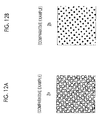
- Fig. 10A is a schematic plan view of the dot image 6 according to a comparative example.
- the dot image 6 is described in the method of JP4375050B (claim 1, [0152] to [0155], Fig. 26, etc.), and is an image which is obtained by applying the threshold matrix 42 illustrated in Fig. 5A .
- JP4375050B claim 1, [0152] to [0155], Fig. 26, etc.
- Fig. 10B is a schematic plan view of the dot image 70 according to the embodiment.
- a dot aggregation portion 72 both the “middle sizes” and the “small sizes” are arranged to be aggregated, while the “large sizes” are arranged to be dispersed.
- the dot aggregation portion 72 is formed through arrangement for dispersion of the dots 14 with the "large size” which is the largest dot size, and is formed through arrangement for aggregation of the dots 14 with the "small size” which is the smallest dot size.
- the dots 14 are arranged such that the smaller the dot size thereof, the higher the aggregability thereof, and the larger the dot size thereof, the lower the aggregability thereof. Thereby, it is possible to reduce the size of the dot clusters which are likely to become large, and it is possible to further reduce noise and graininess of the image.
- the "aggregability" means a total amount of dots aggregated.
- the dot images 10 and 12 may be appropriate for the dot image signals provided for image formation, and may be appropriate for image signals which are obtained by reading actually formed images through a scanner apparatus or the like.
- Figs. 11A to 12B schematically illustrate positions of the arranged dots 14 (refer to Fig. 2 ) that form a so-called AM-type halftone dot image.
- Fig. 11A is a dot pattern 80 illustrating positions of the arranged dots 14 ( Fig. 2 ) common to the dot image 10 of Fig. 1 A and the dot image 2 of Fig. 20A .
- the dot pattern 80 corresponds to a binary image that represents the pixels 64, which are hatched in the image region 62 illustrated in Fig. 8A , in black color (ON).
- Fig. 11B is a dot pattern 10a illustrating positions of the "small size” dots 14S ( Fig. 2 ) arranged in the dot image 10 of Fig. 1 A .
- the dot pattern 10a corresponds to a binary image that represents the pixels 64, which are hatched in the image region 62 illustrated in Fig. 8B , in black color (ON).
- the "small size" dots 14S are arranged to be aggregated (or to be partially semi-aggregated).
- Fig. 11C is a dot pattern 10b illustrating positions of the "large size” dots 14L ( Fig. 2 ) arranged in the dot image 10 of Fig. 1A .
- the dot pattern 10b corresponds to a binary image that represents the pixels 64, which are hatched in the image region 62 illustrated in Fig. 8C , in black color (ON).
- the "large size" dots 14L are arranged to be semi-aggregated.
- Fig. 12A is a dot pattern 2a illustrating positions of the "small size” dots 14S ( Fig. 2 ) arranged in the dot image 2 of Fig. 20A .
- the "small size” dots 14S are arranged to be aggregated.
- Fig. 12B is a dot pattern 2b illustrating positions of the "large size” dots 14L ( Fig. 2 ) arranged in the dot image 2 of Fig. 20A .
- the "large size” dots 14L are arranged to be aggregated.
- spectrums features of power spectrums (hereinafter simply referred to as spectrums) of the dot images 10 and 12 will be described.
- aggregability of the dots 14 is defined on the basis of a power spectrum of a binary image in which whether or not each dot 14 with a specific dot size in the dot image 10 or the like is present is represented by a binary value.
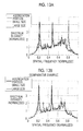
- Fig. 13A is a graph illustrating power spectrums which are obtained by applying Fourier transform to the respective dot patterns 80, 10a, and 10b of Figs. 11A to 11C .
- the horizontal axis of the graph indicates a normalized spatial frequency
- the vertical axis of the graph indicates a normalized spectrum intensity.
- Values in the horizontal axis are linearly normalized such that the zero frequency corresponds to "0" and the Nyquist frequency corresponds to "1".
- Values in the vertical axis are linearly normalized such that a value of the integral of a power spectrum at the spatial frequency is set to 1. Definitions of the horizontal axis and the vertical axis are the same for Figs. 13B , 16A, and 16B to be described later.
- a graph (corresponds to the "aggregation portion") of the thick solid line indicates a spectrum intensity of the dot pattern 80 ( Fig. 11 A) .
- This graph has two large peaks near the spatial frequencies of 0.21 and 0.48.
- a graph (corresponds to the "small size") of the dashed line indicates a spectrum intensity of the dot pattern 10a ( Fig. 11B ).
- This graph has two peaks, of which values are slightly smaller than those of the "aggregation portion", at the spatial frequencies (near 0.21 and 0.48) which are substantially the same as those of the "aggregation portion”.
- This graph further has one peak near the spatial frequency of 0.80.
- a graph (corresponds to the "large size") of the thin solid line indicates a spectrum intensity of the dot pattern 10b ( Fig. 11C ).
- This graph has one large peak near the spatial frequency of 0.80.
- this graph further has two peaks near the spatial frequencies of 0.21 and 0.48, but values of the peaks are extremely small as compared with those of the "aggregation portion".
- Fig. 13B is a graph illustrating power spectrums which are obtained by applying Fourier transform to the dot patterns 80, 2a, and 2b of Figs. 11 A, 12A, and 12B .
- any of graphs of the "aggregation portion", the "small size”, and the “large size” has two large peaks near the spatial frequencies of 0.21 and 0.48.
- Figs. 14A to 15B schematically illustrate positions of the arranged dots 14 (refer to Fig. 2 ) that form a so-called FM-type halftone dot image.
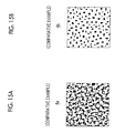
- Fig. 14A is a dot pattern 82 illustrating positions of the arranged dots 14 ( Fig. 2 ) common to the dot image 12 of Fig. 1B and the dot image 4 of Fig. 20B .
- Fig. 14B is a dot pattern 12a illustrating positions of the "small size” dots 14S ( Fig. 2 ) arranged in the dot image 12 of Fig. 1B .
- the "small size” dots 14S are arranged to be aggregated (or to be partially semi-aggregated).
- Fig. 14C is a dot pattern 12b illustrating positions of the "large size” dots 14L ( Fig. 2 ) arranged in the dot image 12 of Fig. 1B .
- the "large size” dots 14L are arranged to be semi-aggregated.
- Fig. 15A is a dot pattern 4a illustrating positions of the "small size” dots 14S ( Fig. 2 ) arranged in the dot image 4 of Fig. 20B .
- the "small size” dots 14S are arranged to be aggregated.
- Fig. 15B is a dot pattern 4b illustrating positions of the "large size” dots 14L ( Fig. 2 ) arranged in the dot image 4 of Fig. 20B .
- the "large size” dots 14L are arranged to be aggregated.
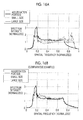
- Fig. 16A is a graph illustrating power spectrums which are obtained by applying Fourier transform to the respective dot patterns 82, 12a, and 12b of Figs. 14A to 14C .
- a graph (corresponds to the "aggregation portion") of the thick solid line indicates a spectrum intensity of the dot pattern 82 ( Fig. 14A ), This graph has one large peak near the spatial frequency of 0.17.
- a graph (corresponds to the "small size") of the dashed line indicates a spectrum intensity of the dot pattern 12a ( Fig. 14B ).
- This graph has one group of peaks, of which values are slightly smaller than those of the "aggregation portion", at the spatial frequency which is substantially the same as that of the "aggregation portion”.
- This graph further has a spectrum component having a large width near the spatial frequency of 0.86.
- a graph (corresponds to the "large size") of the thin solid line indicates a spectrum intensity of the dot pattern 12b ( Fig. 14C ).
- This graph has one group of large peaks near the spatial frequency of 0.86.
- this graph further has one group of peaks near the spatial frequency of 0.17, but values of the peaks are extremely small as compared with those of the "aggregation portion”.
- Fig. 16B is a graph illustrating power spectrums which are obtained by applying Fourier transform to the dot patterns 82, 4a, and 4b of Figs. 14A , 15A, and 15B .
- any of graphs of the "aggregation portion", the "small size”, and the "large size” has one large peak near the spatial frequency of 0.17.
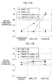
- Fig. 17A is a graph illustrating peak frequencies of the power spectrums.
- the "peak frequency” means a spatial frequency corresponding to the maximum value of the power spectrum.
- example (AM) and the “example (FM)” in the present drawing and Fig. 17B to be described later respectively indicate characteristics of the dot image 10 of Fig. 1A and characteristics of the dot image 12 of Fig. 1B .
- comparativative example (AM) and the “comparative example (FM)” in the present drawing and Fig. 17B respectively indicate characteristics of the dot image 2 of Fig. 20A and characteristics of the dot image 4 of Fig. 20B .
- the dots 14 are arranged such that the smaller the dot size thereof, the lower the spatial frequency (peak frequency), which corresponds to the maximum value of the power spectrum, and the larger the dot size thereof, the higher the spatial frequency.
- Fig. 17B is a graph illustrating centroid frequencies of the power spectrums.
- the "centroid frequency” means a spatial frequency corresponding to a centroid (an average value of first moments) of the power spectrum.
- the dots 14 are arranged such that the smaller the dot size thereof, the lower the spatial frequency (centroid frequency), which corresponds to the centroid of the power spectrum, and the larger the dot size thereof, the higher the spatial frequency.
- a halftone processing section 34 that generates a dot image signal indicating states of the dots 14 by performing halftone processing on the continuous tone image signal indicating an image, and at least one of the dot aggregation portions 16, 18, 68, and 72 is formed on a part of the dot images 10, 12, 66, and 70 which are indicated by the dot image signals, through arrangement for aggregation of the dots 14 (dots 14L and 14S) with two or more dot sizes, when the continuous tone image signal is a signal indicating a tint image.
- the dot aggregation portions 16, 18, 68, and 72 are formed through arrangement for non-aggregation of the dots 14 (dots 14L) with at least one dot size.
- the halftone processing section 34 forms at least one of the dot aggregation portions 16, 18, 68, and 72 on a part of the dot images 10, 12, 66, and 70 which are indicated by the dot image signals, through arrangement for aggregation of the dots 14 (dots 14L and 14S) with two or more dot sizes.
- the halftone processing section 34 forms the dot aggregation portions 16, 18, 68, and 72 through arrangement for non-aggregation of dots 14 (dots 14L) with at least one dot size among the two or more dot sizes. In such a manner, halftone processing is performed on the continuous tone image signal.
- At least one of the dot aggregation portion 16 and the like is formed through the arrangement for aggregation of the dots 14L and 14S with the two or more dot sizes, on a part of the dot image 10 or the like, and each of the dot aggregation portions 16 and the like is formed through the arrangement for non-aggregation of the dots 14L with at least one dot size. Therefore, sizes of clusters of dots with at least one dot size become small, and thus the shapes thereof becomes unlikely to be perceived by an observer. Thereby, it is possible to reduce noise and graininess of an image even when the dots 14 with the plurality of dot sizes are arranged to be aggregated.
- Fig. 18 is a cross-sectional side view illustrating a configuration of the image formation device 100.
- the image formation device 100 is provided with a sheet feeding and transport section 114 which feeds and transports the sheets 22 on the upstream side in the transport direction of the sheet 22 (cut sheets in this example of the drawing).
- the following components are provided on the downstream side of the sheet feeding and transport section 114 in the transport direction of the sheet 22: a treatment liquid application section 116 which applies a treatment liquid on a recording surface (hereinafter referred to as an image formation surface) of the sheet 22; an image formation section 118 which forms an image by adhering the liquid droplets 28 (refer to Fig.
- an ink drying section 120 which dries ink of a treatment liquid layer formed on the sheet 22
- an image fixing section 122 which fixes the image of the treatment liquid layer to the sheet 22
- a discharge section 124 which discharges the sheet 22 to which the image is fixed.
- the sheet feeding and transport section 114 includes a stacking portion 126 which is provided so as to stack the sheets 22, a sheet feeding portion 128 which feeds the sheets 22 stacked on the stacking portion 126 one by one, and a transport portion 130 which transports the sheet 22 fed by the sheet feeding portion 128 to the treatment liquid application section 116.
- the treatment liquid application section 116 includes a treatment liquid application drum 132 which is rotatably provided, a treatment liquid application device 134 which applies a treatment liquid on the image formation surface of the sheet 22, and a treatment liquid drying device 136 which dries the treatment liquid. Thereby, a thin treatment liquid layer is applied on the image formation surface of the sheet 22.
- a first intermediate transport drum 138 which is rotatably provided, is disposed between the treatment liquid application section 116 and the image formation section 118.
- the first intermediate transport drum 138 is rotated in a state in which the sheet 22 is held on the surface of the first intermediate transport drum 138, and thus the sheet 22 supplied from the treatment liquid application section 116 side is transported to the image formation section 118 side.
- the image formation section 118 includes an image formation drum 140 (transport portion) which is rotatably provided, and a head unit 142 which ejects the liquid droplets 28 onto the sheet 22 transported by the image formation drum 140.
- the head unit 142 includes the recording heads 26 of at least Y (yellow), M (magenta), C (cyan), and K (black) which are primary colors.
- the respective recording heads 26 are line heads arranged along the circumferential direction of the image formation drum 140. Thereby, images of the respective colors are sequentially formed on the treatment liquid layer applied on the image formation surface of the sheet 22.
- the treatment liquid has an effect of condensing color materials (pigments) and latex particles dispersed in a solvent of the ink, and is thus able to prevent the color materials from flowing on the sheet 22.
- a second intermediate transport drum 146 which is rotatably provided, is disposed between the image formation section 118 and the ink drying section 120.
- the second intermediate transport drum 146 is rotated in a state in which the sheet 22 is held on the surface of the second intermediate transport drum 146, and thus the sheet 22 supplied from the image formation section 118 side is transported to the ink drying section 120 side.
- the ink drying section 120 includes an ink drying drum 148 which is rotatably provided, and a plurality of hot air nozzles 150 and a plurality of infrared heaters (heaters 152) which dry the treatment liquid layer of the sheet 22. With such a configuration, the solvent of the ink, which stays in the treatment liquid layer of the sheet 22, is dried.
- a third intermediate transport drum 154 which is rotatably provided, is disposed between the ink drying section 120 and the image fixing section 122.
- the third intermediate transport drum 154 is rotated in a state in which the sheet 22 is held on the surface of the third intermediate transport drum 154, and thus the sheet 22 supplied from the ink drying section 120 side is transported to the image fixing section 122 side.
- the image fixing section 122 includes an image fixing drum 156 which is rotatably provided, a heating roller 158 which is disposed so as to be close to the surface of the image fixing drum 156, and a fixing roller 160 which is disposed in a state where the roller is pressed in contact with the surface of the image fixing drum 156. Therefore, the latex particles condensed in the treatment liquid layer are heated and pressed so as to be melted, and are thus fixed as an image onto the sheet 22.
- the sheet 22, onto which the image of the image formation surface is fixed through the above-described respective steps, is transported to the discharge section 124 side provided on the downstream side of the image fixing section 122 through rotation of the image fixing drum 156.
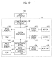
- Fig. 19 is an electrical block diagram illustrating a system configuration of the image formation device 100 illustrated in Fig. 18 .
- the image formation device 100 includes not only the head driver 24 (refer to Fig. 3 ), the head unit 142, and the heater 152 (refer to Fig. 18 with regard to both of the two), but also a communication interface 162, a system controller 164, an image memory 166, a ROM 168, a motor driver 170, a motor 172, a heater driver 174, a printing control section 176 (including the image processing section 20 of Fig. 3 ), an image buffer memory 180, and a ROM 182.
- the communication interface 162 is a section that interfaces with a host apparatus 190, and is used for a user to instruct the image formation device 100 to form an image or the like.
- the communication interface 162 may employ a serial interface such as a universal serial bus (USB), IEEE1394, Ethernet (registered trademark), or a wireless network, or a parallel interface such as Centronics.
- a buffer memory, which is not illustrated, for speeding up communication may be mounted in this section.
- An image signal which is sent from the host apparatus 190, is received by the image formation device 100 through the communication interface 162, and is temporarily stored in the image memory 166.
- the image memory 166 is storage means for storing an image signal input through the communication interface 162, and reads and writes information through the system controller 164.
- the image memory 166 is not limited to a memory formed by semiconductor elements, and may use a magnetic medium such as a hard disk.
- the system controller 164 includes a central processing unit (CPU) and peripheral circuits.
- the system controller 164 functions as a control device that controls the overall image formation device 100 in accordance with a predetermined program, and functions as a calculation device that performs various calculations.
- the system controller 164 controls the respective sections such as the communication interface 162, the image memory 166, the motor driver 170, and the heater driver 174.
- the system controller 164 performs communication control with the host apparatus 190, reading and writing control of the image memory 166 and the ROM 168, and the like.
- the system controller 164 generates control signals for controlling the motor 172 and the heaters 152 of the sheet transport system.
- an image signal stored in the image memory 166 as well as the control signal is transmitted to the printing control section 176.
- the ROM 168 stores programs, which are executed by the CPU of the system controller 164, and a variety of data which is necessary for control.
- the image memory 166 is used as a temporary storage region for an image signal and is used as a development region of a program and a calculation work region of the CPU.
- the motor driver 170 is a driver (driving circuit) which drives the motor 172 of the sheet transport system in accordance with an instruction from the system controller 164.
- the heater driver 174 is a driver which drives the heaters 152 in accordance with an instruction from the system controller 164.
- the printing control section 176 includes a CPU and peripheral circuits, and performs processes such as correction and various processings for generating an ejection control signal from the image signal within the image memory 166 under the control of the system controller 164.
- the image processing section 20 performs image processing including halftone processing on the input image signal, thereby generating a dot image signal, which indicates positions (ink ejection timing) of the formed dots 14, for each color plate.
- the printing control section 176 has an ink ejection data generation function of generating ink ejection data (a control signal of the actuators corresponding to the nozzles of the head unit 142) on the basis of the dot image signal, which is generated by the image processing section 20, and a driving waveform generation function of generating driving signal waveforms for driving the actuators corresponding to the nozzles of the head unit 142.
- the signal (driving waveform) generated in the printing control section 176 is supplied to the head driver 24 so as to control an ink ejection operation of the head unit 142. That is, the head driver 24 controls the head unit 142 such that it sequentially forms dots 14 in a state where the sheet 22 is moved relative to the head unit 142.
- the printing control section 176 includes the image buffer memory 180, and an image signal or data such as parameters is temporarily stored in the image buffer memory 180 when the printing control section 176 processes the image signal.
- the printing control section 176 is connected to the ROM 182 which stores programs executed by the CPU of the printing control section 176 and a variety of data which is necessary for control.
- the ROM 182 may be read only storage means, but preferably utilizes rewritable storage means such as an EEPROM in a case where a variety of data is updated as necessary.
- the image processing section 20 is included in the printing control section 176.
- the image processing section 20 may be formed as an apparatus (for example, a computer) separate from the printing control section 176 or the system controller 164.
- various types of a mechanism for ejecting the liquid droplets 28 through the recording head 26 may be employed.
- a type ejecting liquid droplets of ink through deformation of actuators formed by for example piezoelectric elements or the like may be employed.
- a thermal jet type may be employed in which a heating element such as a heater heats ink so as to generate bubbles and the liquid droplets are ejected by a pressure thereof.
- the recording head 26 is not limited to the line head, and may be applied to a multi-pass type image formation device that forms an image while reciprocating the head to scan the sheet 22 in the width direction (the X direction of Fig. 3 ).
- the ink-jet-type image formation device is exemplified, but the present invention is not limited to this.
- the present invention can be applied to any type (for example, an electrophotographic type) which forms dots 14 on a recording medium.
- a wide format printing apparatus is exemplified, but the scope of the present invention is not limited to this. It may be possible to apply the present invention to image formation devicees other than the wide format printing apparatus. Further, the present invention is not limited to the graphic art (printing) application.
- the present invention can be applied to various image formation devicees capable of forming an image pattern, such as a wire drawing apparatus of an electronic circuit board, a manufacturing device of various devices, a resist printing apparatus using a resin liquid as a functional liquid for ejection, and a micro-structure forming apparatus.
Landscapes
- Engineering & Computer Science (AREA)
- Multimedia (AREA)
- Signal Processing (AREA)
- Physics & Mathematics (AREA)
- Discrete Mathematics (AREA)
- General Physics & Mathematics (AREA)
- Facsimile Image Signal Circuits (AREA)
- Image Processing (AREA)
- Ink Jet (AREA)
Applications Claiming Priority (2)
| Application Number | Priority Date | Filing Date | Title |
|---|---|---|---|
| JP2013019776A JP5953244B2 (ja) | 2013-02-04 | 2013-02-04 | 画像形成装置、方法、プログラム及び画像形成物 |
| PCT/JP2014/051210 WO2014119440A1 (fr) | 2013-02-04 | 2014-01-22 | Dispositif, procédé et programme de formation d'image, et image formée |
Publications (3)
| Publication Number | Publication Date |
|---|---|
| EP2953338A1 true EP2953338A1 (fr) | 2015-12-09 |
| EP2953338A4 EP2953338A4 (fr) | 2016-01-27 |
| EP2953338B1 EP2953338B1 (fr) | 2019-10-30 |
Family
ID=51262153
Family Applications (1)
| Application Number | Title | Priority Date | Filing Date |
|---|---|---|---|
| EP14745424.3A Active EP2953338B1 (fr) | 2013-02-04 | 2014-01-22 | Dispositif, procédé et programme de formation d'image, et image formée |
Country Status (4)
| Country | Link |
|---|---|
| US (1) | US9387685B2 (fr) |
| EP (1) | EP2953338B1 (fr) |
| JP (1) | JP5953244B2 (fr) |
| WO (1) | WO2014119440A1 (fr) |
Cited By (1)
| Publication number | Priority date | Publication date | Assignee | Title |
|---|---|---|---|---|
| EP2953339A4 (fr) * | 2013-02-04 | 2016-03-23 | Fujifilm Corp | Dispositif, procédé et programme de formation d'image |
Families Citing this family (2)
| Publication number | Priority date | Publication date | Assignee | Title |
|---|---|---|---|---|
| JP6790343B2 (ja) * | 2015-10-16 | 2020-11-25 | セイコーエプソン株式会社 | ドット記録装置、ドット記録物の生産方法、コンピュータープログラム |
| JP7807938B2 (ja) | 2022-02-25 | 2026-01-28 | 株式会社Screenホールディングス | 閾値マトリクス生成方法、画像データ生成方法、プログラム、閾値マトリクスおよび画像データ生成装置 |
Family Cites Families (14)
| Publication number | Priority date | Publication date | Assignee | Title |
|---|---|---|---|---|
| DE69132912T2 (de) * | 1990-11-22 | 2002-07-11 | Canon K.K., Tokio/Tokyo | Abbildungsverfahren und -gerät |
| JP3503511B2 (ja) * | 1999-02-05 | 2004-03-08 | セイコーエプソン株式会社 | 印刷装置、印刷方法およびプリンタ |
| WO2005009734A2 (fr) * | 2003-07-31 | 2005-02-03 | Nissim Einat | Procede et appareil d'impression par jet d'encre |
| US7511857B2 (en) * | 2004-01-26 | 2009-03-31 | Hewlett-Packard Development Company, L.P. | Halftoning method and system |
| JP4375050B2 (ja) | 2004-02-20 | 2009-12-02 | セイコーエプソン株式会社 | 所定領域内に形成されるドット個数の情報に基づいて画像を出力する画像出力システム |
| JP4363382B2 (ja) * | 2004-11-25 | 2009-11-11 | セイコーエプソン株式会社 | 印刷用画像処理装置および画像処理方法 |
| JP4518924B2 (ja) * | 2004-11-29 | 2010-08-04 | 株式会社リコー | 画像処理方法、プリンタドライバ、画像処理装置、画像形成装置及び画像形成システム |
| JP2006168073A (ja) * | 2004-12-14 | 2006-06-29 | Canon Inc | インクジェット記録システム |
| JP2006311533A (ja) * | 2005-04-01 | 2006-11-09 | Seiko Epson Corp | 印刷装置、印刷プログラム、印刷方法、および画像処理装置、画像処理プログラム、画像処理方法、ならびに前記プログラムを記録した記録媒体 |
| JP4564979B2 (ja) * | 2006-04-11 | 2010-10-20 | キヤノン株式会社 | データ処理装置、記録装置およびマスクパターンの製造方法 |
| US7513589B2 (en) * | 2007-01-31 | 2009-04-07 | Hewlett-Packard Development Company, L.P. | Multipass printing |
| JP2010245627A (ja) * | 2009-04-01 | 2010-10-28 | Seiko Epson Corp | ディザマスク作成方法および印刷装置 |
| JP5702621B2 (ja) * | 2011-02-10 | 2015-04-15 | 株式会社Screenホールディングス | 画像記録装置および画像記録方法 |
| JP2014012374A (ja) * | 2012-07-05 | 2014-01-23 | Seiko Epson Corp | 印刷方法および印刷装置 |
-
2013
- 2013-02-04 JP JP2013019776A patent/JP5953244B2/ja active Active
-
2014
- 2014-01-22 EP EP14745424.3A patent/EP2953338B1/fr active Active
- 2014-01-22 WO PCT/JP2014/051210 patent/WO2014119440A1/fr not_active Ceased
-
2015
- 2015-07-24 US US14/807,891 patent/US9387685B2/en active Active
Cited By (1)
| Publication number | Priority date | Publication date | Assignee | Title |
|---|---|---|---|---|
| EP2953339A4 (fr) * | 2013-02-04 | 2016-03-23 | Fujifilm Corp | Dispositif, procédé et programme de formation d'image |
Also Published As
| Publication number | Publication date |
|---|---|
| JP5953244B2 (ja) | 2016-07-20 |
| JP2014150510A (ja) | 2014-08-21 |
| EP2953338A4 (fr) | 2016-01-27 |
| US20150328901A1 (en) | 2015-11-19 |
| EP2953338B1 (fr) | 2019-10-30 |
| US9387685B2 (en) | 2016-07-12 |
| WO2014119440A1 (fr) | 2014-08-07 |
Similar Documents
| Publication | Publication Date | Title |
|---|---|---|
| US9144998B2 (en) | Printing method and printing apparatus | |
| JP6442294B2 (ja) | 画像データ生成方法、画像記録方法、画像データ生成装置および画像記録装置 | |
| US9387685B2 (en) | Image formation device, method, program, and formed image | |
| JP2005041041A (ja) | インクジェット印刷のためのエッジ処理 | |
| JP5462891B2 (ja) | 画像形成装置及び画像形成方法 | |
| JP5748522B2 (ja) | インクジェット記録装置およびインクジェット記録方法 | |
| US9259940B2 (en) | Image formation device, method and program | |
| US20120314234A1 (en) | Image processing apparatus, image printing apparatus and image processing method | |
| JP5702621B2 (ja) | 画像記録装置および画像記録方法 | |
| JP6307939B2 (ja) | 画像形成装置、及び、画像形成方法 | |
| JP2006264301A (ja) | 印刷装置、印刷プログラム、印刷方法、および画像処理装置、画像処理プログラム、画像処理方法、ならびに前記プログラムを記録した記録媒体 | |
| JP5940495B2 (ja) | 画像形成装置及び画像形成方法 | |
| US9162498B2 (en) | Ink jet printing apparatus and image processing apparatus | |
| JP5608631B2 (ja) | 画像形成装置及び画像形成方法 | |
| JP2013123831A (ja) | 画像形成装置及び画像形成方法 | |
| JP5953226B2 (ja) | 閾値マトリクス作成装置、方法、プログラム及び画像形成装置 | |
| JP2007068202A (ja) | 印刷装置、印刷プログラム、印刷方法、および画像処理装置、画像処理プログラム、画像処理方法、ならびに前記プログラムを記録した記録媒体 | |
| US9227400B2 (en) | Ejection condition determination method, image forming method, and image forming apparatus | |
| WO2018056967A1 (fr) | Sélection de qualité de mode d'impression | |
| JP2025038997A (ja) | 吐出量上限値決定方法、及び、印刷装置 | |
| WO2025069613A1 (fr) | Dispositif d'impression, système d'impression, procédé d'impression et programme de commande d'impression |
Legal Events
| Date | Code | Title | Description |
|---|---|---|---|
| PUAI | Public reference made under article 153(3) epc to a published international application that has entered the european phase |
Free format text: ORIGINAL CODE: 0009012 |
|
| 17P | Request for examination filed |
Effective date: 20150720 |
|
| AK | Designated contracting states |
Kind code of ref document: A1 Designated state(s): AL AT BE BG CH CY CZ DE DK EE ES FI FR GB GR HR HU IE IS IT LI LT LU LV MC MK MT NL NO PL PT RO RS SE SI SK SM TR |
|
| AX | Request for extension of the european patent |
Extension state: BA ME |
|
| A4 | Supplementary search report drawn up and despatched |
Effective date: 20160104 |
|
| RIC1 | Information provided on ipc code assigned before grant |
Ipc: H04N 1/405 20060101AFI20151218BHEP Ipc: B41J 2/01 20060101ALI20151218BHEP Ipc: G06T 5/00 20060101ALI20151218BHEP |
|
| DAX | Request for extension of the european patent (deleted) | ||
| STAA | Information on the status of an ep patent application or granted ep patent |
Free format text: STATUS: EXAMINATION IS IN PROGRESS |
|
| 17Q | First examination report despatched |
Effective date: 20161024 |
|
| GRAP | Despatch of communication of intention to grant a patent |
Free format text: ORIGINAL CODE: EPIDOSNIGR1 |
|
| STAA | Information on the status of an ep patent application or granted ep patent |
Free format text: STATUS: GRANT OF PATENT IS INTENDED |
|
| INTG | Intention to grant announced |
Effective date: 20190320 |
|
| GRAS | Grant fee paid |
Free format text: ORIGINAL CODE: EPIDOSNIGR3 |
|
| GRAJ | Information related to disapproval of communication of intention to grant by the applicant or resumption of examination proceedings by the epo deleted |
Free format text: ORIGINAL CODE: EPIDOSDIGR1 |
|
| GRAL | Information related to payment of fee for publishing/printing deleted |
Free format text: ORIGINAL CODE: EPIDOSDIGR3 |
|
| STAA | Information on the status of an ep patent application or granted ep patent |
Free format text: STATUS: EXAMINATION IS IN PROGRESS |
|
| INTC | Intention to grant announced (deleted) | ||
| GRAP | Despatch of communication of intention to grant a patent |
Free format text: ORIGINAL CODE: EPIDOSNIGR1 |
|
| STAA | Information on the status of an ep patent application or granted ep patent |
Free format text: STATUS: GRANT OF PATENT IS INTENDED |
|
| GRAA | (expected) grant |
Free format text: ORIGINAL CODE: 0009210 |
|
| STAA | Information on the status of an ep patent application or granted ep patent |
Free format text: STATUS: THE PATENT HAS BEEN GRANTED |
|
| INTG | Intention to grant announced |
Effective date: 20190912 |
|
| AK | Designated contracting states |
Kind code of ref document: B1 Designated state(s): AL AT BE BG CH CY CZ DE DK EE ES FI FR GB GR HR HU IE IS IT LI LT LU LV MC MK MT NL NO PL PT RO RS SE SI SK SM TR |
|
| REG | Reference to a national code |
Ref country code: GB Ref legal event code: FG4D |
|
| REG | Reference to a national code |
Ref country code: CH Ref legal event code: EP |
|
| REG | Reference to a national code |
Ref country code: AT Ref legal event code: REF Ref document number: 1197374 Country of ref document: AT Kind code of ref document: T Effective date: 20191115 |
|
| REG | Reference to a national code |
Ref country code: IE Ref legal event code: FG4D |
|
| REG | Reference to a national code |
Ref country code: DE Ref legal event code: R096 Ref document number: 602014055939 Country of ref document: DE |
|
| REG | Reference to a national code |
Ref country code: LT Ref legal event code: MG4D |
|
| PG25 | Lapsed in a contracting state [announced via postgrant information from national office to epo] |
Ref country code: PT Free format text: LAPSE BECAUSE OF FAILURE TO SUBMIT A TRANSLATION OF THE DESCRIPTION OR TO PAY THE FEE WITHIN THE PRESCRIBED TIME-LIMIT Effective date: 20200302 Ref country code: LV Free format text: LAPSE BECAUSE OF FAILURE TO SUBMIT A TRANSLATION OF THE DESCRIPTION OR TO PAY THE FEE WITHIN THE PRESCRIBED TIME-LIMIT Effective date: 20191030 Ref country code: SE Free format text: LAPSE BECAUSE OF FAILURE TO SUBMIT A TRANSLATION OF THE DESCRIPTION OR TO PAY THE FEE WITHIN THE PRESCRIBED TIME-LIMIT Effective date: 20191030 Ref country code: FI Free format text: LAPSE BECAUSE OF FAILURE TO SUBMIT A TRANSLATION OF THE DESCRIPTION OR TO PAY THE FEE WITHIN THE PRESCRIBED TIME-LIMIT Effective date: 20191030 Ref country code: NO Free format text: LAPSE BECAUSE OF FAILURE TO SUBMIT A TRANSLATION OF THE DESCRIPTION OR TO PAY THE FEE WITHIN THE PRESCRIBED TIME-LIMIT Effective date: 20200130 Ref country code: GR Free format text: LAPSE BECAUSE OF FAILURE TO SUBMIT A TRANSLATION OF THE DESCRIPTION OR TO PAY THE FEE WITHIN THE PRESCRIBED TIME-LIMIT Effective date: 20200131 Ref country code: PL Free format text: LAPSE BECAUSE OF FAILURE TO SUBMIT A TRANSLATION OF THE DESCRIPTION OR TO PAY THE FEE WITHIN THE PRESCRIBED TIME-LIMIT Effective date: 20191030 Ref country code: BG Free format text: LAPSE BECAUSE OF FAILURE TO SUBMIT A TRANSLATION OF THE DESCRIPTION OR TO PAY THE FEE WITHIN THE PRESCRIBED TIME-LIMIT Effective date: 20200130 Ref country code: NL Free format text: LAPSE BECAUSE OF FAILURE TO SUBMIT A TRANSLATION OF THE DESCRIPTION OR TO PAY THE FEE WITHIN THE PRESCRIBED TIME-LIMIT Effective date: 20191030 Ref country code: ES Free format text: LAPSE BECAUSE OF FAILURE TO SUBMIT A TRANSLATION OF THE DESCRIPTION OR TO PAY THE FEE WITHIN THE PRESCRIBED TIME-LIMIT Effective date: 20191030 Ref country code: LT Free format text: LAPSE BECAUSE OF FAILURE TO SUBMIT A TRANSLATION OF THE DESCRIPTION OR TO PAY THE FEE WITHIN THE PRESCRIBED TIME-LIMIT Effective date: 20191030 |
|
| REG | Reference to a national code |
Ref country code: NL Ref legal event code: MP Effective date: 20191030 |
|
| PG25 | Lapsed in a contracting state [announced via postgrant information from national office to epo] |
Ref country code: HR Free format text: LAPSE BECAUSE OF FAILURE TO SUBMIT A TRANSLATION OF THE DESCRIPTION OR TO PAY THE FEE WITHIN THE PRESCRIBED TIME-LIMIT Effective date: 20191030 Ref country code: IS Free format text: LAPSE BECAUSE OF FAILURE TO SUBMIT A TRANSLATION OF THE DESCRIPTION OR TO PAY THE FEE WITHIN THE PRESCRIBED TIME-LIMIT Effective date: 20200229 Ref country code: RS Free format text: LAPSE BECAUSE OF FAILURE TO SUBMIT A TRANSLATION OF THE DESCRIPTION OR TO PAY THE FEE WITHIN THE PRESCRIBED TIME-LIMIT Effective date: 20191030 |
|
| PG25 | Lapsed in a contracting state [announced via postgrant information from national office to epo] |
Ref country code: AL Free format text: LAPSE BECAUSE OF FAILURE TO SUBMIT A TRANSLATION OF THE DESCRIPTION OR TO PAY THE FEE WITHIN THE PRESCRIBED TIME-LIMIT Effective date: 20191030 |
|
| PG25 | Lapsed in a contracting state [announced via postgrant information from national office to epo] |
Ref country code: EE Free format text: LAPSE BECAUSE OF FAILURE TO SUBMIT A TRANSLATION OF THE DESCRIPTION OR TO PAY THE FEE WITHIN THE PRESCRIBED TIME-LIMIT Effective date: 20191030 Ref country code: RO Free format text: LAPSE BECAUSE OF FAILURE TO SUBMIT A TRANSLATION OF THE DESCRIPTION OR TO PAY THE FEE WITHIN THE PRESCRIBED TIME-LIMIT Effective date: 20191030 Ref country code: CZ Free format text: LAPSE BECAUSE OF FAILURE TO SUBMIT A TRANSLATION OF THE DESCRIPTION OR TO PAY THE FEE WITHIN THE PRESCRIBED TIME-LIMIT Effective date: 20191030 Ref country code: DK Free format text: LAPSE BECAUSE OF FAILURE TO SUBMIT A TRANSLATION OF THE DESCRIPTION OR TO PAY THE FEE WITHIN THE PRESCRIBED TIME-LIMIT Effective date: 20191030 |
|
| REG | Reference to a national code |
Ref country code: DE Ref legal event code: R097 Ref document number: 602014055939 Country of ref document: DE |
|
| REG | Reference to a national code |
Ref country code: AT Ref legal event code: MK05 Ref document number: 1197374 Country of ref document: AT Kind code of ref document: T Effective date: 20191030 |
|
| PG25 | Lapsed in a contracting state [announced via postgrant information from national office to epo] |
Ref country code: SM Free format text: LAPSE BECAUSE OF FAILURE TO SUBMIT A TRANSLATION OF THE DESCRIPTION OR TO PAY THE FEE WITHIN THE PRESCRIBED TIME-LIMIT Effective date: 20191030 Ref country code: MC Free format text: LAPSE BECAUSE OF FAILURE TO SUBMIT A TRANSLATION OF THE DESCRIPTION OR TO PAY THE FEE WITHIN THE PRESCRIBED TIME-LIMIT Effective date: 20191030 Ref country code: IT Free format text: LAPSE BECAUSE OF FAILURE TO SUBMIT A TRANSLATION OF THE DESCRIPTION OR TO PAY THE FEE WITHIN THE PRESCRIBED TIME-LIMIT Effective date: 20191030 Ref country code: SK Free format text: LAPSE BECAUSE OF FAILURE TO SUBMIT A TRANSLATION OF THE DESCRIPTION OR TO PAY THE FEE WITHIN THE PRESCRIBED TIME-LIMIT Effective date: 20191030 |
|
| REG | Reference to a national code |
Ref country code: CH Ref legal event code: PL |
|
| PLBE | No opposition filed within time limit |
Free format text: ORIGINAL CODE: 0009261 |
|
| STAA | Information on the status of an ep patent application or granted ep patent |
Free format text: STATUS: NO OPPOSITION FILED WITHIN TIME LIMIT |
|
| 26N | No opposition filed |
Effective date: 20200731 |
|
| REG | Reference to a national code |
Ref country code: BE Ref legal event code: MM Effective date: 20200131 |
|
| PG25 | Lapsed in a contracting state [announced via postgrant information from national office to epo] |
Ref country code: LU Free format text: LAPSE BECAUSE OF NON-PAYMENT OF DUE FEES Effective date: 20200122 Ref country code: FR Free format text: LAPSE BECAUSE OF NON-PAYMENT OF DUE FEES Effective date: 20200131 |
|
| PG25 | Lapsed in a contracting state [announced via postgrant information from national office to epo] |
Ref country code: SI Free format text: LAPSE BECAUSE OF FAILURE TO SUBMIT A TRANSLATION OF THE DESCRIPTION OR TO PAY THE FEE WITHIN THE PRESCRIBED TIME-LIMIT Effective date: 20191030 Ref country code: BE Free format text: LAPSE BECAUSE OF NON-PAYMENT OF DUE FEES Effective date: 20200131 Ref country code: AT Free format text: LAPSE BECAUSE OF FAILURE TO SUBMIT A TRANSLATION OF THE DESCRIPTION OR TO PAY THE FEE WITHIN THE PRESCRIBED TIME-LIMIT Effective date: 20191030 Ref country code: CH Free format text: LAPSE BECAUSE OF NON-PAYMENT OF DUE FEES Effective date: 20200131 Ref country code: LI Free format text: LAPSE BECAUSE OF NON-PAYMENT OF DUE FEES Effective date: 20200131 |
|
| PG25 | Lapsed in a contracting state [announced via postgrant information from national office to epo] |
Ref country code: IE Free format text: LAPSE BECAUSE OF NON-PAYMENT OF DUE FEES Effective date: 20200122 |
|
| PGFP | Annual fee paid to national office [announced via postgrant information from national office to epo] |
Ref country code: GB Payment date: 20210113 Year of fee payment: 8 |
|
| PG25 | Lapsed in a contracting state [announced via postgrant information from national office to epo] |
Ref country code: TR Free format text: LAPSE BECAUSE OF FAILURE TO SUBMIT A TRANSLATION OF THE DESCRIPTION OR TO PAY THE FEE WITHIN THE PRESCRIBED TIME-LIMIT Effective date: 20191030 Ref country code: MT Free format text: LAPSE BECAUSE OF FAILURE TO SUBMIT A TRANSLATION OF THE DESCRIPTION OR TO PAY THE FEE WITHIN THE PRESCRIBED TIME-LIMIT Effective date: 20191030 Ref country code: CY Free format text: LAPSE BECAUSE OF FAILURE TO SUBMIT A TRANSLATION OF THE DESCRIPTION OR TO PAY THE FEE WITHIN THE PRESCRIBED TIME-LIMIT Effective date: 20191030 |
|
| PG25 | Lapsed in a contracting state [announced via postgrant information from national office to epo] |
Ref country code: MK Free format text: LAPSE BECAUSE OF FAILURE TO SUBMIT A TRANSLATION OF THE DESCRIPTION OR TO PAY THE FEE WITHIN THE PRESCRIBED TIME-LIMIT Effective date: 20191030 |
|
| GBPC | Gb: european patent ceased through non-payment of renewal fee |
Effective date: 20220122 |
|
| PG25 | Lapsed in a contracting state [announced via postgrant information from national office to epo] |
Ref country code: GB Free format text: LAPSE BECAUSE OF NON-PAYMENT OF DUE FEES Effective date: 20220122 |
|
| P01 | Opt-out of the competence of the unified patent court (upc) registered |
Effective date: 20230515 |
|
| PGFP | Annual fee paid to national office [announced via postgrant information from national office to epo] |
Ref country code: DE Payment date: 20251203 Year of fee payment: 13 |