EP2953570B1 - Dispositif et système d'éclairage chirurgical ajustable - Google Patents
Dispositif et système d'éclairage chirurgical ajustable Download PDFInfo
- Publication number
- EP2953570B1 EP2953570B1 EP14707545.1A EP14707545A EP2953570B1 EP 2953570 B1 EP2953570 B1 EP 2953570B1 EP 14707545 A EP14707545 A EP 14707545A EP 2953570 B1 EP2953570 B1 EP 2953570B1
- Authority
- EP
- European Patent Office
- Prior art keywords
- housing
- light
- overhead
- handle
- surgical
- Prior art date
- Legal status (The legal status is an assumption and is not a legal conclusion. Google has not performed a legal analysis and makes no representation as to the accuracy of the status listed.)
- Not-in-force
Links
Images




Classifications
-
- F—MECHANICAL ENGINEERING; LIGHTING; HEATING; WEAPONS; BLASTING
- F21—LIGHTING
- F21V—FUNCTIONAL FEATURES OR DETAILS OF LIGHTING DEVICES OR SYSTEMS THEREOF; STRUCTURAL COMBINATIONS OF LIGHTING DEVICES WITH OTHER ARTICLES, NOT OTHERWISE PROVIDED FOR
- F21V21/00—Supporting, suspending, or attaching arrangements for lighting devices; Hand grips
- F21V21/14—Adjustable mountings
- F21V21/32—Flexible tubes
-
- A—HUMAN NECESSITIES
- A61—MEDICAL OR VETERINARY SCIENCE; HYGIENE
- A61B—DIAGNOSIS; SURGERY; IDENTIFICATION
- A61B46/00—Surgical drapes
- A61B46/10—Surgical drapes specially adapted for instruments, e.g. microscopes
-
- A—HUMAN NECESSITIES
- A61—MEDICAL OR VETERINARY SCIENCE; HYGIENE
- A61B—DIAGNOSIS; SURGERY; IDENTIFICATION
- A61B90/00—Instruments, implements or accessories specially adapted for surgery or diagnosis and not covered by any of the groups A61B1/00 - A61B50/00, e.g. for luxation treatment or for protecting wound edges
- A61B90/30—Devices for illuminating a surgical field, the devices having an interrelation with other surgical devices or with a surgical procedure
-
- F—MECHANICAL ENGINEERING; LIGHTING; HEATING; WEAPONS; BLASTING
- F21—LIGHTING
- F21L—LIGHTING DEVICES OR SYSTEMS THEREOF, BEING PORTABLE OR SPECIALLY ADAPTED FOR TRANSPORTATION
- F21L4/00—Electric lighting devices with self-contained electric batteries or cells
- F21L4/04—Electric lighting devices with self-contained electric batteries or cells characterised by the provision of a light source housing portion adjustably fixed to the remainder of the device
-
- F—MECHANICAL ENGINEERING; LIGHTING; HEATING; WEAPONS; BLASTING
- F21—LIGHTING
- F21V—FUNCTIONAL FEATURES OR DETAILS OF LIGHTING DEVICES OR SYSTEMS THEREOF; STRUCTURAL COMBINATIONS OF LIGHTING DEVICES WITH OTHER ARTICLES, NOT OTHERWISE PROVIDED FOR
- F21V21/00—Supporting, suspending, or attaching arrangements for lighting devices; Hand grips
- F21V21/08—Devices for easy attachment to any desired place, e.g. clip, clamp, magnet
-
- F—MECHANICAL ENGINEERING; LIGHTING; HEATING; WEAPONS; BLASTING
- F21—LIGHTING
- F21V—FUNCTIONAL FEATURES OR DETAILS OF LIGHTING DEVICES OR SYSTEMS THEREOF; STRUCTURAL COMBINATIONS OF LIGHTING DEVICES WITH OTHER ARTICLES, NOT OTHERWISE PROVIDED FOR
- F21V23/00—Arrangement of electric circuit elements in or on lighting devices
- F21V23/06—Arrangement of electric circuit elements in or on lighting devices the elements being coupling devices, e.g. connectors
-
- A—HUMAN NECESSITIES
- A61—MEDICAL OR VETERINARY SCIENCE; HYGIENE
- A61B—DIAGNOSIS; SURGERY; IDENTIFICATION
- A61B17/00—Surgical instruments, devices or methods
- A61B2017/00681—Aspects not otherwise provided for
- A61B2017/00734—Aspects not otherwise provided for battery operated
-
- A—HUMAN NECESSITIES
- A61—MEDICAL OR VETERINARY SCIENCE; HYGIENE
- A61B—DIAGNOSIS; SURGERY; IDENTIFICATION
- A61B90/00—Instruments, implements or accessories specially adapted for surgery or diagnosis and not covered by any of the groups A61B1/00 - A61B50/00, e.g. for luxation treatment or for protecting wound edges
- A61B90/30—Devices for illuminating a surgical field, the devices having an interrelation with other surgical devices or with a surgical procedure
- A61B2090/306—Devices for illuminating a surgical field, the devices having an interrelation with other surgical devices or with a surgical procedure using optical fibres
-
- A—HUMAN NECESSITIES
- A61—MEDICAL OR VETERINARY SCIENCE; HYGIENE
- A61B—DIAGNOSIS; SURGERY; IDENTIFICATION
- A61B90/00—Instruments, implements or accessories specially adapted for surgery or diagnosis and not covered by any of the groups A61B1/00 - A61B50/00, e.g. for luxation treatment or for protecting wound edges
- A61B90/30—Devices for illuminating a surgical field, the devices having an interrelation with other surgical devices or with a surgical procedure
- A61B2090/308—Lamp handles
-
- F—MECHANICAL ENGINEERING; LIGHTING; HEATING; WEAPONS; BLASTING
- F21—LIGHTING
- F21W—INDEXING SCHEME ASSOCIATED WITH SUBCLASSES F21K, F21L, F21S and F21V, RELATING TO USES OR APPLICATIONS OF LIGHTING DEVICES OR SYSTEMS
- F21W2131/00—Use or application of lighting devices or systems not provided for in codes F21W2102/00-F21W2121/00
- F21W2131/20—Lighting for medical use
Definitions
- a device that relates generally to lighting used in the performance of a surgical or other medical procedure and, more particularly, to an adjustable light device that may be detachably connected to an overhead light whereby the light may be brought in close proximity with objects to be illuminated.
- Surgical lighting generally includes overhead lighting, head lamps worn by the surgeons and lighted instruments placed within a wound. Sufficient lighting of the tissues is critical in surgery so that the surgeon can accurately identify the tissues in order to make sure that the appropriate tissues are targeted while avoiding damage to surrounding vascular and neural structures. For example, in a minimally invasive spinal fusion, the surgeon will need to identify bony structures, remove degenerated intervertebral disc tissues and avoid any damage to the spinal cord, peripheral nerves and vascular structures. In addition, should a structure be unintentionally damaged, powerful and targeted lighting may be needed to allow for rapid and complete surgical repair.
- Overhead lights are large and expensive dual (or more) lighting systems affixed to the ceiling of the operating room.
- the overhead lighting systems broadly direct light downward onto the patient and surgical field.
- Generally cylindrical handles on the overhead lights may be used by the surgeons to manually adjust the direction of the light.
- Sterile coverings are used for the light handles.
- a sterile light handle cover may be threaded onto the handle.
- the handle cover may be a thin, flexible plastic piece adapted to slip over the handle.
- overhead surgical lighting systems provide good lighting of the surgical field and patient surface, but provide less direct and targeted lighting down into the body cavity. This is especially true for small incision situations seen in minimally invasive surgery. However, because the light source is above the surgeon's head, leaning in toward the surgical site may obscure the light source and create shadows.
- Fiber optic lighting systems anchored to their foreheads with a targeted beam shining downward.
- the light beam may be adjusted to focus directly downward along the path of the surgeon's view.
- These systems can provide targeted light into smaller incisions.
- these systems commonly become less targeted over the course of a surgical procedure and need to be re-adjusted by the non-sterile nursing staff since they are not sterile systems.
- head lamps When head lamps are worn by multiple surgeons in the same procedure, the two head lamps may bump into one another.
- these systems typically require anchorage to a light source and a power source resting on a stand behind the operating surgeon. This can limit the surgeon's mobility, as well as creating a tripping hazard in the operating room.
- Surgical instruments placed down into the wound may be provided with illumination sources.
- illumination sources In one example, this involves the addition of lighting cables to surgical retractors. While this solution does provide for more directed lighting in the work space, the light cables add expense, take up working space and may require enlarging the incision, and can generate heat. Cases of skin burns or even burning or melting of draping have been reported.
- a hand-held and separate light source, such as a surgical wand or probe, may also be used, but this still requires a cable for lighting with coincident issues of heating and impeding of the operative field.
- US 2004/264193 A1 discloses an adjustable light for a medical environment including an overhead light having a light handle, the adjustable light comprising proximal part adapted for engagement with the handle of the overhead light, a distal end including a lamp operatively connected to a power source for generating illuminating light and a flexible shaft extending there between.
- the light device should be adjustable for selectively targeting the light to a preferred location.
- the new light device will work in conjunction with available lighting systems.
- an adjustable light for use in a medical environment including an overhead light having a light handle, as claimed in claim 1.
- the adjustable light comprises a first housing adapted for engagement with the handle of the overhead light, a second housing including a lamp operatively connected to a power source for generating illuminating light, and a flexible shaft extending between and interconnecting the first housing at a proximal end of the shaft and the second housing at a distal end of the shaft.
- the first housing is adapted to be releasably coupled to the handle of the overhead light over a work area such that the flexible arm and the second housing are selectively movable relative to the first housing toward a target in the work area for illuminating the target.
- a lighting system is also provided for a medical environment including a ceiling.
- the lighting system comprises an overhead light adapted to be suspended from the ceiling, the overhead light including a handle, a first housing configured for engagement with the handle of the overhead light, a second housing including a lamp operatively connected to a power source for generating illuminating light, and a flexible shaft extending between and interconnecting the first housing at a proximal end of the shaft and the second housing at a distal end of the shaft.
- the first housing is releasably coupled to the overhead light over a work area such that the flexible arm and the second housing are selectively movable relative to the first housing toward a target in the work area for illuminating the target.
- the surgical light device and system described herein contemplates a device and a procedure that is implemented in the setting of a surgical environment for providing lighting into the surgical working space created by an incision.
- Access to the internal working space may be secured by a trocar, tube or bladed retractors, for example.
- lighting of the internal cavity is required for a safe and accurate surgical procedure. Lighting of the surgical working space may be especially challenging in so-called “minimally invasive” or “minimal incision” procedures where the amount of tissue incised is minimized and, therefore, a small opening is available for directing light into the body.
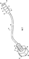
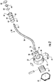
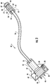
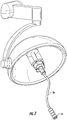
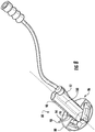
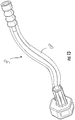
- FIGs. 1-3 An embodiment of a surgical light device is shown in FIGs. 1-3 and generally designated at 30.
- the surgical lighting device 30 comprises a proximal anchor member 32 fabricated, for example, of a medical grade polymer and a distal light assembly 34.
- An intermediate flexible shaft 36 extends between and interconnects the anchor member 32 and the light assembly 34.
- the flexible shaft 36 enables the light assembly 34 to be moved independently of the anchor member 32.
- one embodiment of the anchor member 32 comprises a housing 38 and a removable proximal cover 40.
- the housing 38 defines an interior cavity 42.
- a hollow central axial projection 44 extends distally from the housing 38.
- the distal end of the projection 44 has a hole 46 opening into the interior of the projection 44 and the cavity 42 of the housing 38.
- the cover 40 has a central axial threaded flange 48 extending proximally from the housing 38.
- the threaded flange 48 is used to threadably connect the anchor member 32 to an overhead light, which
- the housing 38 may be configured to accommodate batteries 50 for providing a power to the light assembly 34 in a conventional manner.
- the housing 38 is provided with a peripheral opening 52 for accessing the batteries for insertion or replacement.
- the opening 52 is selectively accessed via a panel 54 which is mounted on a hinge 55 to the housing 38.
- An integrated battery case 56 may be provided for holding the batteries 50.
- a rechargeable battery pack (not shown) or a battery pack having a power cord (not shown) may be used to power the light assembly 34.
- An adaptor connection may be provided in the housing 38 for recharging.
- the batteries 50 are configured to provide sufficient power for about 6 to about 8 hours of light.
- the batteries 50 can be replaced after a fixed period for very long usage times during, for example, lengthy surgical procedures.
- the anchor member 32 may be connected to a source of A.C. electrical power via a conventional power cord (not shown) as a means for conveying power from the power source.
- the housing 38 is generally hexagonal in transverse cross-section. It is understood that this is merely exemplary and that the housing 38 may be configured in any number of convenient shapes, including cylindrical, cubic or even irregular. Moreover, the size of the housing 38 may vary to accommodate the internal components, including the batteries, or to correspond to the configuration of an overhead light for attachment to the overhead light. For example, a relatively large housing 38 may be used to accommodate more batteries 50 and increase the illumination output. Accordingly, the surgical light device 30 is adaptable to various applications and environments.
- An on-off switch 58 is provided on the housing 48 of the anchor member 32 for allowing the user to selectively actuate the light assembly 34.
- the switch 58 can be closed by means of a push button 60 which completes a circuit between the batteries 50, or other power source, and the light assembly 34 in a conventional manner.
- the light assembly 34 comprises a generally cylindrical head portion 62, a PC board 64 including a driver and an LED light source, a lens 66, and a retaining ring 68.
- the head portion 62 is preferably formed from anodized aluminum and serves as a heat sink for dissipating the heat of the LED.
- the head portion 62 defines a central axial through bore of varying diameter.
- the head portion 62 defining the bore at the proximal end 70 is threaded and is sized to receive the distal end of the flexible shaft 36.
- the intermediate portion of the bore 72 has a much smaller diameter and is sized sufficiently for passing electrical wiring to the PC board.
- the bore at the distal end 74 of the head portion 62 is configured to receive the PC board 64, the lens 66 and the retaining ring 68.
- the lens 66 is bell-shaped and defines an opening at a small end thereof through which the LED extends.
- the retaining ring 68 overlies the periphery of the front surface of the lens 66.
- the change in diameter of the bore from the intermediate portion 72 of the bore to the distal end 74 of the head portion 62 forms a seat in the head portion for supporting the PC board 64.
- the retaining ring 68 is secured in place with adhesive for securing the components in the distal end 74 of the head portion 62.
- the periphery of the head portion 62 has a plurality of axially-spaced circumferential grooves 63 to aid in the handling of the head portion.
- the LED light source of the light assembly 34 generates substantial light without appreciable heat generation.
- a variety of light emitting diodes in a variety of colors may be used. The use of different colors may provide for reduced eye strain for the surgical team or may help to better identify and differentiate different types of tissues at the surgical site. Additionally, multiple lights may be used during the procedure, either attached at a common anchor point or attached to separate surgical lights. The use of various intensity and wavelength lights is also contemplated, allowing the surgical team to select the appropriate light at the time of surgery. Lights allowing for use of fluorescent tracers in the operative space may be useful in targeting, for example, tumors of the cranial space or breast tissue.
- UV light source As an alternative to an LED light source, other suitable light sources may be used, including a conventional halogen bulb with an integral reflector. Ultraviolet (UV) irradiation could also be delivered at the distal end of the shaft 36 to provide for localized killing of pathogenic agents on the skin or at the operative site.
- a mercury high pressure lamp, a metal vapor or xenon high pressure lamp or super pressure lamps, or a tungsten filament incandescent lamp are suitable.
- the flexible shaft 36 comprises a hollow tubular element formed from a flexible material, such as a plastic or metal.
- a suitable flexible framework may be constructed from a thin-walled corrugated metal tube; however, it is understood that the flexible framework may comprise other components, such as interconnected circular rings or wire portions, alternating metal and composite members, universally rotatable or pivotable members, and the like.
- the flexible shaft 36 permits manual deformation for adjusting the position of the light assembly 34, which remains fixed indefinitely until readjusted by the user.
- a suitable flexible shaft is sold as a flex arm available from Moffatt Products Inc. of Watertown, South Dakota.
- Each of the ends of the shaft 36 includes an externally threaded fitting 76.
- the distal end of the projection 44 on the housing 48 of the anchor member 32 is internally threaded for threadingly engaging the fitting 76 at the proximal end of the shaft 36.
- the proximal end of the head portion 62 of the light assembly 34 is internally threaded for threadingly engaging the distal end 78 of the shaft 36.
- the length of the shaft 36 may vary to suit the environment such as, for example, a particular operative suite.
- the flexible shaft 34 may comprise a retractable mechanism for deploying only a length of shaft 36 necessary for a particular application.
- the diameter flexible shaft 36 is essentially identical along its length between the proximal end 76 and the distal end 78 of the shaft.
- Electrical wiring extends axially through the shaft 36 between the batteries 50, or other power source, in the anchor member 32 to the light assembly 34.
- the electrical power is transmitted via the wiring from the anchor member 32 and along the shaft 36 to the light assembly 34 for illuminating an area for medical treatment purposes.
- some embodiments may need to anticipate the need for nested wiring corridors such as those incorporated into the surgical lighting system 30. Such a design anticipates a high volume and disposable device that may be useful in large scale applications in hospitals, surgical centers and outpatient clinics and physician offices.
- the surgical light device 30 is adapted to connect to an overhead light.
- overhead surgical or medical lights are provided with generally cylindrical handles for manually adjusting the direction of the light.
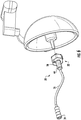
- the surgical light device 30 is configured to operatively connect to the handle 83 of the overhead surgical light 82 for adjustable, targeted surgical lighting.
- the threaded flange 48 extending proximally from the cover 40 may be threaded onto the handle.
- the cover 40 may define a central axial opening into the cavity 42 of the housing and the hollow projection 44 for slidingly receiving the handle 83 of the overhead light 82.
- the handle 83 slips into the cavity 42 defined by the housing 38 and within the bore defined by the axial projection 44 of the anchor member 32.
- An embodiment of a slide-on surgical light device is shown in FIG. 8 and generally designated at 80.
- the surgical light device 80 is suitable for use with an overhead surgical light including a camera 84 integrated into the handle 83.
- the surgical light device 80 comprises an anchor member 86, including a housing 88 and a distal projection 90 defining a central longitudinal passage 92 therethrough.
- the flexible shaft 36 is affixed to the distal end of the projection 90 in a position offset from the opening of the passage 92.
- This configuration allows for a line-of-sight through the opening of the passage 92 for the camera 84, providing a surgical lighting system comprising the overhead camera operatively associated with flexible and adjustable surgical light device 80.
- the surgical light device 80 may further comprise a releasable locking mechanism 94.
- the locking mechanism 94 comprises a cam 96 and an integral lever 98 pivotally mounted on the projection 90 of the anchor member 32.
- the projection 90 defines an opening 100 into the passage 92 for receiving the cam 96.
- the lever 98 allows the user to manually pivot the cam 96 relative to the projection 90 to a locking position where the cam 96 extends into the passage 92 for frictionally securing the anchor member 86 to the handle 83 of the overhead surgical light 82.
- This arrangement is suitable for use with the overhead surgical light 82 and camera 84 as well as other slide-on embodiments of the surgical light device 30, 80 for securely attaching the anchor member 32 to the overhead light.
- the locking mechanism 94 is activated with one hand for positively engaging the handle 83 of the overhead surgical light 82. It is understood that the locking mechanism 94 is similarly easily released for removing the surgical light device 80.
- Threaded or slide-on connection of the surgical light device 30, 80 to an overhead light provides a reliable and convenient means for mounting the surgical light device 30, 80 for use.
- the surgical light device 30, 80 is not in any way limited to the connecting or mounting means described herein, but may alternately comprise any other suitable arrangement which enables connection of the surgical light device 30, 80 to the overhead light.
- the means of attaching the surgical light device 30, 80 described herein are exemplary and other means of attachment are possible, such as adhesive bonding, mechanical fastening, snap-fit coupling and the like.
- the surgical light device 30, 80 may be provided at inception of a surgery in a pre-sterilized condition within a sterile pouch (not shown). A member of the surgical team will open the sterile pouch to access the surgical light device 30, 80 and mount the anchor member 32 to the handle of the overhead surgical light ( FIGs. 6 and 7 ). Once in position on the overhead light, the user may grasp the head portion 62 of the light assembly 34 or the flexible shaft 36 and manually direct the light assembly 34 at a target in the surgical field for illumination thereof. It is understood that the flexible shaft 36 then functions to maintain the position of the light assembly 34 by resisting movement of the shaft 36 from its selected shape. At the same time, the flexible shaft 36 is still selectively movable to illuminate another target in a second position as needed.
- the surgical light device 30, 80 may also serve as a platform for other functions.
- a digital camera 102 is shown at the distal end of the shaft 36.
- the surgical light device 30, 80 combines a light source 34 and adjacent camera 102 for capturing still or motion images.
- the camera 102 may be self-contained, including a lens and recording, processing and removable media storage capability, or the camera may allow for remote image transmission to a distant unit for processing, viewing and recording.
- the distal end of the shaft 36 provides an ideal location for the functional aspects of the camera 102 adjacent to the operative space, which further aids visualization of the work area.
- a plurality of surgical light devices 30, 80 may be combined for the same effect, wherein a surgical light device may comprise the camera 102 and a second surgical light device 30, 80 anchored from the same or another overhead surgical light provides a light assembly 34.
- the distal end of the flexible shaft 36 may have other uses beyond lighting or image recording and transmission.
- the light assembly 34 could be used as storage for delivery of an agent, such as a local topical antibiotic for local antisepsis.
- the agent could be stored in the anchor member 32 and delivered at the distal end of the shaft 36, as needed, by the surgical team. It is understood that this use is merely exemplary of the utility of proximal storage in the anchor member 32 and delivery at the distal end of the shaft 36.
- Other opportunities using the surgical light device 30, 80 for storage and delivery in a surgical setting will be apparent to those of ordinary skill in the art.
- a disposable sterile sleeve 120 may be provided for enclosing the surgical light device 30.
- the sterile sleeve 120 is a clear, plastic tubular element closed at one end for receiving the surgical light device 30, 80.
- elastic bands 122 at a proximal end and a distal end secure the sleeve 120 to the surgical light device 30, 80 ( FIG. 10 ).
- a plurality of elastic cords 124 running the length of the sleeve 120 can be used for securely conforming the sterile sleeve 120 to the surgical light device 30, 80.
- the elastic cords 124 do not obscure the light at the end of the light assembly 34.
- a plurality of pinch holes 126 are provided in the anchor member 32 for holding the sterile sleeve 120 in place over the surgical light device 30, 80.
- the sterile sleeve 120 can be a thermo-formed or injection molded tube that fits snugly, or snaps into place, over the surgical light device 30, 80.
- the surgical lighting device 30, 80 described herein has many advantages and is particularly useful for delivering targeted and adjustable light to a work area during a surgical procedure.
- the surgical light device 30, 80 utilizes existing overhead light systems for secure and adjustable anchorage provided by the handles on the overhead lighting.
- the flexibility of the shaft 34 allows the operating team to direct the light 36 into the surgical site at angles not achievable with an overhead surgical light or a head lamp.
- the various orientations downward into the surgical working space achieved by the flexible shaft is effectively infinite.
- Applications for the adjustable light device 30, 80 are wide ranging, specifically to a wide range of medical procedures in the areas of surgery where incisions into the body require lighting for direct visualization of internal structures, including orthopedics, cardiovascular surgery, neurosurgery, oncology, plastic surgery and wide range of other surgical approaches.
- the surgical light device 30, 80 is especially well-suited for minimally invasive surgery, sometimes called minimal incision surgery. In these procedures, small incisions are used and the surgeon requires well targeted illumination to light the working space within the body.
- the surgical light device and system has been shown and described in considerable detail with respect to only a few exemplary embodiments thereof, it should be understood by those skilled in the art that we do not intend to limit our to the embodiments since various modifications, omissions and additions may be made to the disclosed embodiments without materially departing from the novel teachings and advantages, particularly in light of the foregoing teachings.
- the surgical light device may be mounted to any suitable overhead structure, or to structure that is not overhead.
Landscapes
- Health & Medical Sciences (AREA)
- Engineering & Computer Science (AREA)
- Surgery (AREA)
- Life Sciences & Earth Sciences (AREA)
- General Engineering & Computer Science (AREA)
- Molecular Biology (AREA)
- Heart & Thoracic Surgery (AREA)
- Medical Informatics (AREA)
- Biomedical Technology (AREA)
- Animal Behavior & Ethology (AREA)
- General Health & Medical Sciences (AREA)
- Public Health (AREA)
- Veterinary Medicine (AREA)
- Nuclear Medicine, Radiotherapy & Molecular Imaging (AREA)
- Oral & Maxillofacial Surgery (AREA)
- Pathology (AREA)
- Surgical Instruments (AREA)
- Non-Portable Lighting Devices Or Systems Thereof (AREA)
Claims (13)
- Éclairage ajustable pour un environnement médical comprenant un éclairage suspendu ayant une poignée d'éclairage, l'éclairage ajustable comprenant :un élément d'ancrage (32, 86) adapté à se mettre en prise avec la poignée de l'éclairage suspendu, l'élément d'ancrage (32, 86) comprenant :un premier boîtier (38, 88) définissant une cavité intérieure (42), le premier boîtier (38) comprenant des moyens de montage à la poignée de l'éclairage suspendu ;une projection axiale creuse centrale (44, 90) s'étendant à partir de la première poignée (38) ;une source d'énergie (50) disposée à l'intérieur de la cavité du premier boîtier (38, 88) ;un second boîtier comprenant une lampe (34) fonctionnellement raccordée à la source d'énergie (50) pour générer une lumière d'éclairage ;un arbre flexible (36) s'étendant entre et reliant la projection axiale (44, 90) au niveau d'une extrémité proximale de l'arbre et le second boîtier au niveau d'une extrémité distale de l'arbre, etdans lequel l'élément d'ancrage (32, 86) est adapté à être couplé de façon amovible à la poignée de l'éclairage suspendu au-dessus d'une zone de travail de telle sorte que l'arbre flexible (36) et le second boîtier soient sélectivement mobiles relativement au premier boîtier (38, 88) en direction d'une cible dans la zone de travail pour éclairer la cible.
- Éclairage ajustable selon la revendication 1, comprenant en outre un raccord fileté sur le premier boîtier (38, 88), le raccord fileté adapté à se mettre en prise par filetage sur la poignée de l'éclairage suspendu.
- Éclairage ajustable selon la revendication 1, dans lequel la lampe (34) comprend une LED.
- Éclairage ajustable selon la revendication 1, dans lequel la lampe (34) comprend une ampoule à incandescence, un objectif, et un réflecteur.
- Éclairage ajustable selon la revendication 1, dans lequel la source d'énergie comprend des batteries disposées dans le premier boîtier (38, 88).
- Éclairage ajustable selon la revendication 1, dans lequel le premier boîtier (38, 88) comprend une source d'énergie électrique rechargeable (50).
- Éclairage ajustable selon la revendication 5, comprenant en outre un élément conducteur s'étendant du premier boîtier à travers l'arbre flexible jusqu'au second boîtier pour délivrer une énergie du premier boîtier au second boîtier.
- Système d'éclairage pour un environnement médical comprenant un plafond, le système d'éclairage comprenant :un éclairage suspendu adapté à être suspendu du plafond, l'éclairage suspendu comprenant une poignée ; etun éclairage ajustable selon l'une quelconque des revendications 1 à 7.
- Système d'éclairage selon la revendication 8, comprenant en outre un raccord fileté (48) sur le premier boîtier (38), et un raccord fileté sur la poignée de l'éclairage suspendu, dans lequel les raccords filetés sont configurés pour se mettre en prise par filetage pour raccorder le premier boîtier (38) à la poignée de l'éclairage suspendu.
- Système d'éclairage selon la revendication 8, comprenant en outre un mécanisme de fixation (94) pour fixer de manière libérable le premier boîtier (88) à l'éclairage suspendu, et une fixation d'appariement sur l'éclairage suspendu pour faciliter le raccordement détachable du premier boîtier (88) à l'éclairage suspendu.
- Système d'éclairage selon la revendication 10, dans lequel le premier boîtier (88) définit une cavité et une ouverture de l'extérieur dans la cavité, la poignée configurée pour être reçue dans la cavité du premier boîtier (88), et comprenant en outre une came (96) fixée de façon pivotante au premier boîtier (88) adjacente à l'ouverture, la came (96) mobile d'une première position espacée de l'ouverture et s'étendant à travers l'ouverture dans la cavité dans une seconde position pour se mettre en prise avec la poignée et fournir un raccordement sélectivement libérable entre le premier boîtier (88) et l'éclairage suspendu.
- Système d'éclairage selon la revendication 7, comprenant en outre un moyen fonctionnellement associé au second boîtier pour utiliser la source d'énergie (50) .
- Système d'éclairage selon la revendication 12, dans lequel le moyen utilisant l'énergie comprend une caméra.
Applications Claiming Priority (2)
| Application Number | Priority Date | Filing Date | Title |
|---|---|---|---|
| US201361763175P | 2013-02-11 | 2013-02-11 | |
| PCT/US2014/015802 WO2014124438A1 (fr) | 2013-02-11 | 2014-02-11 | Dispositif et système d'éclairage chirurgical ajustable |
Publications (2)
| Publication Number | Publication Date |
|---|---|
| EP2953570A1 EP2953570A1 (fr) | 2015-12-16 |
| EP2953570B1 true EP2953570B1 (fr) | 2018-11-28 |
Family
ID=50190774
Family Applications (1)
| Application Number | Title | Priority Date | Filing Date |
|---|---|---|---|
| EP14707545.1A Not-in-force EP2953570B1 (fr) | 2013-02-11 | 2014-02-11 | Dispositif et système d'éclairage chirurgical ajustable |
Country Status (3)
| Country | Link |
|---|---|
| US (3) | US20140226304A1 (fr) |
| EP (1) | EP2953570B1 (fr) |
| WO (1) | WO2014124438A1 (fr) |
Families Citing this family (17)
| Publication number | Priority date | Publication date | Assignee | Title |
|---|---|---|---|---|
| US20160018091A1 (en) * | 2014-07-18 | 2016-01-21 | Howard J. Markley | Illumination Assembly |
| CN105698103A (zh) * | 2016-01-26 | 2016-06-22 | 盛志娟 | 一种手术用移动冷光源 |
| DE102016013394A1 (de) * | 2016-11-11 | 2018-05-17 | Drägerwerk AG & Co. KGaA | Schutzüberzug für ein Teil eines Medizingeräts |
| EP3498216A1 (fr) * | 2017-12-13 | 2019-06-19 | Ondal Medical Systems GmbH | Dispositif d'éclairage chirurgical et tête d'éclairage pour dispositif d'éclairage chirurgical |
| US10985478B1 (en) | 2018-02-17 | 2021-04-20 | Lumenture, LLC | Low profile lighting adapters |
| USD966601S1 (en) * | 2019-02-19 | 2022-10-11 | Lumenture, Inc. | Lighting track adapter |
| USD905884S1 (en) * | 2019-03-07 | 2020-12-22 | Yuyao Yuchang Electrical Appliance Co., Ltd. | Work lamp |
| USD963236S1 (en) * | 2019-06-13 | 2022-09-06 | Amax Lighting, Inc. | Adjustable screen |
| US10724726B1 (en) * | 2019-06-20 | 2020-07-28 | Nova Wildcat Shur-Line, Llc | Light assembly including an adapter to couple to a work implement |
| CN113531415A (zh) * | 2020-04-14 | 2021-10-22 | 广州迪克医疗器械有限公司 | 观察灯 |
| CN111350977B (zh) * | 2020-04-21 | 2021-11-12 | 南阳市中心医院 | 一种耳鼻喉检查专用照明装置 |
| US11859783B2 (en) * | 2020-06-15 | 2024-01-02 | Good Bison | Convertible light device |
| USD957021S1 (en) * | 2020-09-30 | 2022-07-05 | Guangdong XIAOSHUDIAN Technology Co., Ltd | Grill light |
| US11644187B2 (en) | 2021-04-16 | 2023-05-09 | Augustine Biomedical + Design, LLC | Aerodynamic surgical light and boom systems |
| US11529209B2 (en) | 2021-04-16 | 2022-12-20 | Augustine Biomedical + Design, LLC | Aerodynamic surgical light and boom systems |
| USD1123224S1 (en) * | 2024-08-19 | 2026-04-21 | Shenzhen DanielLED technology Co,. Ltd. | LED light |
| USD1123235S1 (en) * | 2025-01-31 | 2026-04-21 | Rejuvenation, Inc. | Lamp |
Family Cites Families (39)
| Publication number | Priority date | Publication date | Assignee | Title |
|---|---|---|---|---|
| US2648762A (en) * | 1950-12-16 | 1953-08-11 | Milton S Dunkelberger | Combined housing and flexible flashlight support |
| US4597030A (en) * | 1985-01-31 | 1986-06-24 | American Hospital Supply Corporation | Surgical illuminator |
| US4797798A (en) * | 1987-04-10 | 1989-01-10 | Adjustable Fixture Co. | Medical examining lamp |
| JPH0226100Y2 (fr) * | 1987-12-28 | 1990-07-17 | ||
| US5707137A (en) * | 1995-04-11 | 1998-01-13 | Gsl Rechargeable Products, Ltd. | Portable light with a removable flexible intermediate section to permit direct connection between the base portion and light portion |
| FR2734450B3 (fr) * | 1995-05-24 | 1997-04-30 | Hsu Shih Hao | Rateau reglable |
| US5702175A (en) * | 1996-07-15 | 1997-12-30 | Chen; Jenn-Hwang | Movable lamp device |
| US5722764A (en) * | 1996-10-31 | 1998-03-03 | Jou; Wen San | Adjustable flashlight |
| USD411853S (en) * | 1997-11-28 | 1999-07-06 | Mark Cieslikowski | Flexible lens shade |
| EP1137896B1 (fr) * | 1998-12-09 | 2003-07-23 | Steris Inc. | Systeme d'eclairage chirurgical a fibre optique suspendu au plafond, dote d'un commutateur optique et d'un dispositif a lentilles a focale variable manuelle |
| US6601985B1 (en) * | 1999-06-25 | 2003-08-05 | Steris Inc. | Medical lighting systems using electrodeless metal halide lamps and fiber optic light pipes |
| US6280050B1 (en) * | 1999-08-13 | 2001-08-28 | Nordic Technologies, Inc. | Flexible flashlight extension |
| US6257745B1 (en) * | 1999-12-14 | 2001-07-10 | Daimlerchrysler Corporation | Flexible arm light for automobile overhead console |
| US6646383B2 (en) * | 2001-03-15 | 2003-11-11 | Siemens Medical Solutions Usa, Inc. | Monolithic structure with asymmetric coupling |
| US6715904B2 (en) * | 2001-07-19 | 2004-04-06 | Michael L. Naughton | Laser light handle |
| US6808289B2 (en) * | 2001-07-20 | 2004-10-26 | RPM Optoelectronics, LLC | Method and apparatus for flexible led lamp |
| PL373724A1 (en) * | 2001-08-23 | 2005-09-05 | Yukiyasu Okumura | Color temperature-regulable led light |
| CN100402922C (zh) * | 2002-02-25 | 2008-07-16 | 斯特里斯公司 | 可调节的渐进式接头制动装置 |
| US20050242261A1 (en) * | 2002-02-25 | 2005-11-03 | Steris Inc | Surgical suspension system |
| US20040141317A1 (en) * | 2003-01-22 | 2004-07-22 | Modern Pioneer Ltd. | Flashlight |
| US20050171407A1 (en) * | 2003-11-24 | 2005-08-04 | Michael Rosenkranz | Illumination device and method for medical procedures |
| EP1568934B1 (fr) * | 2004-02-28 | 2012-05-30 | TRUMPF Medizin Systeme GmbH + Co. KG | Lampe chirurgicale |
| US7810945B2 (en) * | 2004-07-13 | 2010-10-12 | Mize Randy J | Adjustable light connection |
| US7182490B2 (en) * | 2004-10-18 | 2007-02-27 | Huang-Hsi Hsu | Structure of illumination apparatus |
| US20060127167A1 (en) * | 2004-12-14 | 2006-06-15 | Wu-Hong Hsieh | Transverse quick-release connector |
| US7481554B2 (en) * | 2005-09-15 | 2009-01-27 | Gary Anderson | Battery powered LED lamp |
| US20070081358A1 (en) * | 2005-10-08 | 2007-04-12 | Todd Shea | Medical Illumination Device with a Base |
| US20080146935A1 (en) * | 2006-10-13 | 2008-06-19 | Sen-Yung Liu | Auxiliary Positioning Device For Ultrasonic Apparatus |
| DE202007007054U1 (de) * | 2006-11-15 | 2007-07-26 | Trumpf Kreuzer Medizin Systeme Gmbh + Co. Kg | System mit einer Operationsleuchte und mit einer Kamera |
| TWM327970U (en) * | 2007-10-02 | 2008-03-01 | Tien-Sheng Chen | Surgical operation illumination system with photographic recorder and lighting function |
| US7789526B2 (en) * | 2008-06-23 | 2010-09-07 | B/E Aerospace, Inc. | Quick disconnect lighting system |
| US9062871B2 (en) * | 2008-07-21 | 2015-06-23 | David M. Medinis | LED lamp with air-cooled heat sink |
| US8052311B2 (en) * | 2008-11-26 | 2011-11-08 | Ilo Kristo Xhunga | Pull-down self-supportive lighting mounted on hand-reachable ceilings |
| US8317371B1 (en) * | 2008-12-31 | 2012-11-27 | Koninklijke Philips Electronics N.V. | LED dock light |
| US8052339B2 (en) * | 2009-12-08 | 2011-11-08 | Noel Gharibian | Operating room universal disposable camera cover and adapter system |
| USD632413S1 (en) * | 2010-01-19 | 2011-02-08 | Midmark Corporation | Light for examinations and procedures |
| WO2011103073A1 (fr) * | 2010-02-16 | 2011-08-25 | Midmark Corporation | Lumière à del pour examens et procédures |
| US20130201688A1 (en) * | 2012-02-02 | 2013-08-08 | Karen F. Glass | Adjustable Beam Lamp |
| USD776850S1 (en) * | 2015-01-16 | 2017-01-17 | The Daylight Company (Holdings) Limited | Lamp |
-
2014
- 2014-02-11 WO PCT/US2014/015802 patent/WO2014124438A1/fr not_active Ceased
- 2014-02-11 EP EP14707545.1A patent/EP2953570B1/fr not_active Not-in-force
- 2014-02-11 US US14/177,887 patent/US20140226304A1/en not_active Abandoned
-
2018
- 2018-01-05 US US29/632,110 patent/USD841209S1/en active Active
- 2018-01-05 US US15/862,747 patent/US10458634B2/en not_active Expired - Fee Related
Non-Patent Citations (1)
| Title |
|---|
| None * |
Also Published As
| Publication number | Publication date |
|---|---|
| EP2953570A1 (fr) | 2015-12-16 |
| US20140226304A1 (en) | 2014-08-14 |
| USD841209S1 (en) | 2019-02-19 |
| WO2014124438A1 (fr) | 2014-08-14 |
| US10458634B2 (en) | 2019-10-29 |
| US20180128463A1 (en) | 2018-05-10 |
Similar Documents
| Publication | Publication Date | Title |
|---|---|---|
| US10458634B2 (en) | Adjustable surgical light device and system | |
| US20230078427A1 (en) | Surgical device with light | |
| US10383698B2 (en) | Devices and kits for assisting in open surgeries | |
| US8430813B2 (en) | Illuminated surgical access system including a surgical access device and integrated light emitter | |
| JP6243911B2 (ja) | 外科用点灯装置 | |
| US20070060795A1 (en) | Lighted surgical retractors with LED illumination light engines | |
| ES2599994T3 (es) | Instrumento quirúrgico que incluye característica de alimentación de accesorio | |
| JP7267676B2 (ja) | 照明装置 | |
| US20160184046A1 (en) | Surgical tool lights | |
| ES2343438T3 (es) | Iluminador extensible de pequeño calibre. | |
| CN104902803A (zh) | 腔内照明装置 | |
| US20130163274A1 (en) | Surgical site light | |
| US20180353258A1 (en) | Illuminated retractor | |
| JP2022527729A (ja) | 照明装置をハンドヘルド電気外科用器具に取り付けるためのアダプタアセンブリ | |
| WO2018209347A1 (fr) | Éclairage chirurgical et ses utilisations | |
| US20120323083A1 (en) | Lighting System | |
| US20060229593A1 (en) | Surgical Illumination insert | |
| JP2013022446A (ja) | 骨髄ガイドワイヤと結合可能な横方向発光装置 | |
| CA2990513C (fr) | Dispositifs et kits pour faciliter les chirurgies ouvertes | |
| HK1248501B (zh) | 照明装置 |
Legal Events
| Date | Code | Title | Description |
|---|---|---|---|
| PUAI | Public reference made under article 153(3) epc to a published international application that has entered the european phase |
Free format text: ORIGINAL CODE: 0009012 |
|
| 17P | Request for examination filed |
Effective date: 20150910 |
|
| AK | Designated contracting states |
Kind code of ref document: A1 Designated state(s): AL AT BE BG CH CY CZ DE DK EE ES FI FR GB GR HR HU IE IS IT LI LT LU LV MC MK MT NL NO PL PT RO RS SE SI SK SM TR |
|
| AX | Request for extension of the european patent |
Extension state: BA ME |
|
| RIN1 | Information on inventor provided before grant (corrected) |
Inventor name: BOYD, LAWRENCE M. Inventor name: RATCLIFFE, JOHN J. |
|
| DAX | Request for extension of the european patent (deleted) | ||
| STAA | Information on the status of an ep patent application or granted ep patent |
Free format text: STATUS: EXAMINATION IS IN PROGRESS |
|
| 17Q | First examination report despatched |
Effective date: 20180424 |
|
| REG | Reference to a national code |
Ref country code: DE Ref legal event code: R079 Ref document number: 602014036877 Country of ref document: DE Free format text: PREVIOUS MAIN CLASS: A61B0019000000 Ipc: A61B0090300000 |
|
| RIC1 | Information provided on ipc code assigned before grant |
Ipc: A61B 90/30 20160101AFI20180629BHEP Ipc: A61B 46/10 20160101ALI20180629BHEP |
|
| GRAP | Despatch of communication of intention to grant a patent |
Free format text: ORIGINAL CODE: EPIDOSNIGR1 |
|
| STAA | Information on the status of an ep patent application or granted ep patent |
Free format text: STATUS: GRANT OF PATENT IS INTENDED |
|
| INTG | Intention to grant announced |
Effective date: 20180813 |
|
| RIN1 | Information on inventor provided before grant (corrected) |
Inventor name: BOYD, LAWRENCE M. Inventor name: RATCLIFFE, JOHN J. |
|
| GRAS | Grant fee paid |
Free format text: ORIGINAL CODE: EPIDOSNIGR3 |
|
| GRAA | (expected) grant |
Free format text: ORIGINAL CODE: 0009210 |
|
| STAA | Information on the status of an ep patent application or granted ep patent |
Free format text: STATUS: THE PATENT HAS BEEN GRANTED |
|
| AK | Designated contracting states |
Kind code of ref document: B1 Designated state(s): AL AT BE BG CH CY CZ DE DK EE ES FI FR GB GR HR HU IE IS IT LI LT LU LV MC MK MT NL NO PL PT RO RS SE SI SK SM TR |
|
| REG | Reference to a national code |
Ref country code: CH Ref legal event code: EP |
|
| REG | Reference to a national code |
Ref country code: AT Ref legal event code: REF Ref document number: 1069326 Country of ref document: AT Kind code of ref document: T Effective date: 20181215 |
|
| REG | Reference to a national code |
Ref country code: DE Ref legal event code: R096 Ref document number: 602014036877 Country of ref document: DE |
|
| REG | Reference to a national code |
Ref country code: IE Ref legal event code: FG4D |
|
| REG | Reference to a national code |
Ref country code: NL Ref legal event code: MP Effective date: 20181128 |
|
| REG | Reference to a national code |
Ref country code: LT Ref legal event code: MG4D |
|
| REG | Reference to a national code |
Ref country code: AT Ref legal event code: MK05 Ref document number: 1069326 Country of ref document: AT Kind code of ref document: T Effective date: 20181128 |
|
| PG25 | Lapsed in a contracting state [announced via postgrant information from national office to epo] |
Ref country code: HR Free format text: LAPSE BECAUSE OF FAILURE TO SUBMIT A TRANSLATION OF THE DESCRIPTION OR TO PAY THE FEE WITHIN THE PRESCRIBED TIME-LIMIT Effective date: 20181128 Ref country code: AT Free format text: LAPSE BECAUSE OF FAILURE TO SUBMIT A TRANSLATION OF THE DESCRIPTION OR TO PAY THE FEE WITHIN THE PRESCRIBED TIME-LIMIT Effective date: 20181128 Ref country code: LT Free format text: LAPSE BECAUSE OF FAILURE TO SUBMIT A TRANSLATION OF THE DESCRIPTION OR TO PAY THE FEE WITHIN THE PRESCRIBED TIME-LIMIT Effective date: 20181128 Ref country code: ES Free format text: LAPSE BECAUSE OF FAILURE TO SUBMIT A TRANSLATION OF THE DESCRIPTION OR TO PAY THE FEE WITHIN THE PRESCRIBED TIME-LIMIT Effective date: 20181128 Ref country code: IS Free format text: LAPSE BECAUSE OF FAILURE TO SUBMIT A TRANSLATION OF THE DESCRIPTION OR TO PAY THE FEE WITHIN THE PRESCRIBED TIME-LIMIT Effective date: 20190328 Ref country code: NO Free format text: LAPSE BECAUSE OF FAILURE TO SUBMIT A TRANSLATION OF THE DESCRIPTION OR TO PAY THE FEE WITHIN THE PRESCRIBED TIME-LIMIT Effective date: 20190228 Ref country code: FI Free format text: LAPSE BECAUSE OF FAILURE TO SUBMIT A TRANSLATION OF THE DESCRIPTION OR TO PAY THE FEE WITHIN THE PRESCRIBED TIME-LIMIT Effective date: 20181128 Ref country code: BG Free format text: LAPSE BECAUSE OF FAILURE TO SUBMIT A TRANSLATION OF THE DESCRIPTION OR TO PAY THE FEE WITHIN THE PRESCRIBED TIME-LIMIT Effective date: 20190228 Ref country code: LV Free format text: LAPSE BECAUSE OF FAILURE TO SUBMIT A TRANSLATION OF THE DESCRIPTION OR TO PAY THE FEE WITHIN THE PRESCRIBED TIME-LIMIT Effective date: 20181128 |
|
| PG25 | Lapsed in a contracting state [announced via postgrant information from national office to epo] |
Ref country code: RS Free format text: LAPSE BECAUSE OF FAILURE TO SUBMIT A TRANSLATION OF THE DESCRIPTION OR TO PAY THE FEE WITHIN THE PRESCRIBED TIME-LIMIT Effective date: 20181128 Ref country code: SE Free format text: LAPSE BECAUSE OF FAILURE TO SUBMIT A TRANSLATION OF THE DESCRIPTION OR TO PAY THE FEE WITHIN THE PRESCRIBED TIME-LIMIT Effective date: 20181128 Ref country code: PT Free format text: LAPSE BECAUSE OF FAILURE TO SUBMIT A TRANSLATION OF THE DESCRIPTION OR TO PAY THE FEE WITHIN THE PRESCRIBED TIME-LIMIT Effective date: 20190328 Ref country code: AL Free format text: LAPSE BECAUSE OF FAILURE TO SUBMIT A TRANSLATION OF THE DESCRIPTION OR TO PAY THE FEE WITHIN THE PRESCRIBED TIME-LIMIT Effective date: 20181128 Ref country code: GR Free format text: LAPSE BECAUSE OF FAILURE TO SUBMIT A TRANSLATION OF THE DESCRIPTION OR TO PAY THE FEE WITHIN THE PRESCRIBED TIME-LIMIT Effective date: 20190301 |
|
| PG25 | Lapsed in a contracting state [announced via postgrant information from national office to epo] |
Ref country code: NL Free format text: LAPSE BECAUSE OF FAILURE TO SUBMIT A TRANSLATION OF THE DESCRIPTION OR TO PAY THE FEE WITHIN THE PRESCRIBED TIME-LIMIT Effective date: 20181128 |
|
| PG25 | Lapsed in a contracting state [announced via postgrant information from national office to epo] |
Ref country code: PL Free format text: LAPSE BECAUSE OF FAILURE TO SUBMIT A TRANSLATION OF THE DESCRIPTION OR TO PAY THE FEE WITHIN THE PRESCRIBED TIME-LIMIT Effective date: 20181128 Ref country code: DK Free format text: LAPSE BECAUSE OF FAILURE TO SUBMIT A TRANSLATION OF THE DESCRIPTION OR TO PAY THE FEE WITHIN THE PRESCRIBED TIME-LIMIT Effective date: 20181128 Ref country code: CZ Free format text: LAPSE BECAUSE OF FAILURE TO SUBMIT A TRANSLATION OF THE DESCRIPTION OR TO PAY THE FEE WITHIN THE PRESCRIBED TIME-LIMIT Effective date: 20181128 Ref country code: IT Free format text: LAPSE BECAUSE OF FAILURE TO SUBMIT A TRANSLATION OF THE DESCRIPTION OR TO PAY THE FEE WITHIN THE PRESCRIBED TIME-LIMIT Effective date: 20181128 |
|
| REG | Reference to a national code |
Ref country code: DE Ref legal event code: R097 Ref document number: 602014036877 Country of ref document: DE |
|
| PG25 | Lapsed in a contracting state [announced via postgrant information from national office to epo] |
Ref country code: RO Free format text: LAPSE BECAUSE OF FAILURE TO SUBMIT A TRANSLATION OF THE DESCRIPTION OR TO PAY THE FEE WITHIN THE PRESCRIBED TIME-LIMIT Effective date: 20181128 Ref country code: SM Free format text: LAPSE BECAUSE OF FAILURE TO SUBMIT A TRANSLATION OF THE DESCRIPTION OR TO PAY THE FEE WITHIN THE PRESCRIBED TIME-LIMIT Effective date: 20181128 Ref country code: EE Free format text: LAPSE BECAUSE OF FAILURE TO SUBMIT A TRANSLATION OF THE DESCRIPTION OR TO PAY THE FEE WITHIN THE PRESCRIBED TIME-LIMIT Effective date: 20181128 Ref country code: SK Free format text: LAPSE BECAUSE OF FAILURE TO SUBMIT A TRANSLATION OF THE DESCRIPTION OR TO PAY THE FEE WITHIN THE PRESCRIBED TIME-LIMIT Effective date: 20181128 |
|
| PLBE | No opposition filed within time limit |
Free format text: ORIGINAL CODE: 0009261 |
|
| STAA | Information on the status of an ep patent application or granted ep patent |
Free format text: STATUS: NO OPPOSITION FILED WITHIN TIME LIMIT |
|
| PG25 | Lapsed in a contracting state [announced via postgrant information from national office to epo] |
Ref country code: MC Free format text: LAPSE BECAUSE OF FAILURE TO SUBMIT A TRANSLATION OF THE DESCRIPTION OR TO PAY THE FEE WITHIN THE PRESCRIBED TIME-LIMIT Effective date: 20181128 Ref country code: LU Free format text: LAPSE BECAUSE OF NON-PAYMENT OF DUE FEES Effective date: 20190211 Ref country code: SI Free format text: LAPSE BECAUSE OF FAILURE TO SUBMIT A TRANSLATION OF THE DESCRIPTION OR TO PAY THE FEE WITHIN THE PRESCRIBED TIME-LIMIT Effective date: 20181128 |
|
| 26N | No opposition filed |
Effective date: 20190829 |
|
| REG | Reference to a national code |
Ref country code: BE Ref legal event code: MM Effective date: 20190228 |
|
| REG | Reference to a national code |
Ref country code: IE Ref legal event code: MM4A |
|
| PG25 | Lapsed in a contracting state [announced via postgrant information from national office to epo] |
Ref country code: IE Free format text: LAPSE BECAUSE OF NON-PAYMENT OF DUE FEES Effective date: 20190211 |
|
| PG25 | Lapsed in a contracting state [announced via postgrant information from national office to epo] |
Ref country code: BE Free format text: LAPSE BECAUSE OF NON-PAYMENT OF DUE FEES Effective date: 20190228 |
|
| PG25 | Lapsed in a contracting state [announced via postgrant information from national office to epo] |
Ref country code: TR Free format text: LAPSE BECAUSE OF FAILURE TO SUBMIT A TRANSLATION OF THE DESCRIPTION OR TO PAY THE FEE WITHIN THE PRESCRIBED TIME-LIMIT Effective date: 20181128 |
|
| PG25 | Lapsed in a contracting state [announced via postgrant information from national office to epo] |
Ref country code: MT Free format text: LAPSE BECAUSE OF NON-PAYMENT OF DUE FEES Effective date: 20190211 |
|
| PG25 | Lapsed in a contracting state [announced via postgrant information from national office to epo] |
Ref country code: CY Free format text: LAPSE BECAUSE OF FAILURE TO SUBMIT A TRANSLATION OF THE DESCRIPTION OR TO PAY THE FEE WITHIN THE PRESCRIBED TIME-LIMIT Effective date: 20181128 |
|
| PG25 | Lapsed in a contracting state [announced via postgrant information from national office to epo] |
Ref country code: HU Free format text: LAPSE BECAUSE OF FAILURE TO SUBMIT A TRANSLATION OF THE DESCRIPTION OR TO PAY THE FEE WITHIN THE PRESCRIBED TIME-LIMIT; INVALID AB INITIO Effective date: 20140211 |
|
| PGFP | Annual fee paid to national office [announced via postgrant information from national office to epo] |
Ref country code: GB Payment date: 20220223 Year of fee payment: 9 Ref country code: DE Payment date: 20220217 Year of fee payment: 9 Ref country code: CH Payment date: 20220216 Year of fee payment: 9 |
|
| PGFP | Annual fee paid to national office [announced via postgrant information from national office to epo] |
Ref country code: FR Payment date: 20220216 Year of fee payment: 9 |
|
| PG25 | Lapsed in a contracting state [announced via postgrant information from national office to epo] |
Ref country code: MK Free format text: LAPSE BECAUSE OF FAILURE TO SUBMIT A TRANSLATION OF THE DESCRIPTION OR TO PAY THE FEE WITHIN THE PRESCRIBED TIME-LIMIT Effective date: 20181128 |
|
| REG | Reference to a national code |
Ref country code: DE Ref legal event code: R119 Ref document number: 602014036877 Country of ref document: DE |
|
| REG | Reference to a national code |
Ref country code: CH Ref legal event code: PL |
|
| GBPC | Gb: european patent ceased through non-payment of renewal fee |
Effective date: 20230211 |
|
| PG25 | Lapsed in a contracting state [announced via postgrant information from national office to epo] |
Ref country code: LI Free format text: LAPSE BECAUSE OF NON-PAYMENT OF DUE FEES Effective date: 20230228 Ref country code: CH Free format text: LAPSE BECAUSE OF NON-PAYMENT OF DUE FEES Effective date: 20230228 |
|
| PG25 | Lapsed in a contracting state [announced via postgrant information from national office to epo] |
Ref country code: GB Free format text: LAPSE BECAUSE OF NON-PAYMENT OF DUE FEES Effective date: 20230211 |
|
| PG25 | Lapsed in a contracting state [announced via postgrant information from national office to epo] |
Ref country code: GB Free format text: LAPSE BECAUSE OF NON-PAYMENT OF DUE FEES Effective date: 20230211 Ref country code: FR Free format text: LAPSE BECAUSE OF NON-PAYMENT OF DUE FEES Effective date: 20230228 Ref country code: DE Free format text: LAPSE BECAUSE OF NON-PAYMENT OF DUE FEES Effective date: 20230901 |