EP2953655B1 - Procédé, récipient et agencement pour stérilisation et stockage de dispositifs médicaux - Google Patents
Procédé, récipient et agencement pour stérilisation et stockage de dispositifs médicaux Download PDFInfo
- Publication number
- EP2953655B1 EP2953655B1 EP14702890.6A EP14702890A EP2953655B1 EP 2953655 B1 EP2953655 B1 EP 2953655B1 EP 14702890 A EP14702890 A EP 14702890A EP 2953655 B1 EP2953655 B1 EP 2953655B1
- Authority
- EP
- European Patent Office
- Prior art keywords
- container
- window
- ultraviolet light
- light source
- hollow
- Prior art date
- Legal status (The legal status is an assumption and is not a legal conclusion. Google has not performed a legal analysis and makes no representation as to the accuracy of the status listed.)
- Active
Links
Images


Classifications
-
- A—HUMAN NECESSITIES
- A61—MEDICAL OR VETERINARY SCIENCE; HYGIENE
- A61L—METHODS OR APPARATUS FOR STERILISING MATERIALS OR OBJECTS IN GENERAL; DISINFECTION, STERILISATION OR DEODORISATION OF AIR; CHEMICAL ASPECTS OF BANDAGES, DRESSINGS, ABSORBENT PADS OR SURGICAL ARTICLES; MATERIALS FOR BANDAGES, DRESSINGS, ABSORBENT PADS OR SURGICAL ARTICLES
- A61L2/00—Disinfection or sterilisation of materials or objects, in general; Accessories therefor
- A61L2/02—Disinfection or sterilisation of materials or objects, in general; Accessories therefor using physical processes
- A61L2/08—Radiation
- A61L2/10—Ultraviolet [UV] radiation
-
- A—HUMAN NECESSITIES
- A61—MEDICAL OR VETERINARY SCIENCE; HYGIENE
- A61L—METHODS OR APPARATUS FOR STERILISING MATERIALS OR OBJECTS IN GENERAL; DISINFECTION, STERILISATION OR DEODORISATION OF AIR; CHEMICAL ASPECTS OF BANDAGES, DRESSINGS, ABSORBENT PADS OR SURGICAL ARTICLES; MATERIALS FOR BANDAGES, DRESSINGS, ABSORBENT PADS OR SURGICAL ARTICLES
- A61L2/00—Disinfection or sterilisation of materials or objects, in general; Accessories therefor
- A61L2/26—Accessories
-
- B—PERFORMING OPERATIONS; TRANSPORTING
- B65—CONVEYING; PACKING; STORING; HANDLING THIN OR FILAMENTARY MATERIAL
- B65D—CONTAINERS FOR STORAGE OR TRANSPORT OF ARTICLES OR MATERIALS, e.g. BAGS, BARRELS, BOTTLES, BOXES, CANS, CARTONS, CRATES, DRUMS, JARS, TANKS, HOPPERS, FORWARDING CONTAINERS; ACCESSORIES, CLOSURES, OR FITTINGS THEREFOR; PACKAGING ELEMENTS; PACKAGES
- B65D25/00—Details of other kinds or types of rigid or semi-rigid containers
- B65D25/54—Inspection openings or windows
-
- B—PERFORMING OPERATIONS; TRANSPORTING
- B65—CONVEYING; PACKING; STORING; HANDLING THIN OR FILAMENTARY MATERIAL
- B65D—CONTAINERS FOR STORAGE OR TRANSPORT OF ARTICLES OR MATERIALS, e.g. BAGS, BARRELS, BOTTLES, BOXES, CANS, CARTONS, CRATES, DRUMS, JARS, TANKS, HOPPERS, FORWARDING CONTAINERS; ACCESSORIES, CLOSURES, OR FITTINGS THEREFOR; PACKAGING ELEMENTS; PACKAGES
- B65D81/00—Containers, packaging elements, or packages, for contents presenting particular transport or storage problems, or adapted to be used for non-packaging purposes after removal of contents
- B65D81/18—Containers, packaging elements, or packages, for contents presenting particular transport or storage problems, or adapted to be used for non-packaging purposes after removal of contents providing specific environment for contents, e.g. temperature above or below ambient
-
- A—HUMAN NECESSITIES
- A61—MEDICAL OR VETERINARY SCIENCE; HYGIENE
- A61L—METHODS OR APPARATUS FOR STERILISING MATERIALS OR OBJECTS IN GENERAL; DISINFECTION, STERILISATION OR DEODORISATION OF AIR; CHEMICAL ASPECTS OF BANDAGES, DRESSINGS, ABSORBENT PADS OR SURGICAL ARTICLES; MATERIALS FOR BANDAGES, DRESSINGS, ABSORBENT PADS OR SURGICAL ARTICLES
- A61L2103/00—Materials or objects being the target of disinfection or sterilisation
- A61L2103/15—Laboratory, medical or dentistry appliances, e.g. catheters or sharps
-
- A—HUMAN NECESSITIES
- A61—MEDICAL OR VETERINARY SCIENCE; HYGIENE
- A61L—METHODS OR APPARATUS FOR STERILISING MATERIALS OR OBJECTS IN GENERAL; DISINFECTION, STERILISATION OR DEODORISATION OF AIR; CHEMICAL ASPECTS OF BANDAGES, DRESSINGS, ABSORBENT PADS OR SURGICAL ARTICLES; MATERIALS FOR BANDAGES, DRESSINGS, ABSORBENT PADS OR SURGICAL ARTICLES
- A61L2202/00—Aspects relating to methods or apparatus for disinfecting or sterilising materials or objects
- A61L2202/10—Apparatus features
- A61L2202/12—Apparatus for isolating biocidal substances from the environment
- A61L2202/122—Chambers for sterilisation
-
- A—HUMAN NECESSITIES
- A61—MEDICAL OR VETERINARY SCIENCE; HYGIENE
- A61L—METHODS OR APPARATUS FOR STERILISING MATERIALS OR OBJECTS IN GENERAL; DISINFECTION, STERILISATION OR DEODORISATION OF AIR; CHEMICAL ASPECTS OF BANDAGES, DRESSINGS, ABSORBENT PADS OR SURGICAL ARTICLES; MATERIALS FOR BANDAGES, DRESSINGS, ABSORBENT PADS OR SURGICAL ARTICLES
- A61L2202/00—Aspects relating to methods or apparatus for disinfecting or sterilising materials or objects
- A61L2202/10—Apparatus features
- A61L2202/18—Aseptic storing means
- A61L2202/182—Rigid packaging means
Definitions
- the present invention concerns a method and an arrangement for sterilization and further storage of medical devices, in particular surgical instruments.
- the sterile package is usually a multiple-layer crepe paper bag and/or a plastic bag sealed with Tyvek sheet which offers virtually no protection against shocks or hazards, and only limited protection against recontamination. Actually, crepe paper bag must remain dry to avoid contamination.
- ozone for sterilization in various domains, for example for air purification, water processing, food processing or sterilization of medical devices.
- US8,048,370 discloses a method and an apparatus for purifying air, and suggests sterilization with ozone and ozonite by irradiating water vapour. Ozone could be destroyed by Ultraviolet UV-C irradiation.
- US2003/0133832 discloses a method to disintox buildings, mail rooms, offices or other enclosed spaces after a contamination with nerve gases or anthrax.
- WO2004/062800 discloses another method for neutralizing or destroying airborne pathogens, such as spores, bacteria and viruses, or chemical toxins in commercial air handling systems.
- US2012/0056102 discloses a disinfection unit for disinfecting the entire surface of an item used in the food production chain.
- the disinfection box comprises a hollow, at least one ultraviolet light source within the hollow, reflective interiors for redirecting UV lights, an UV-transparent shelf for item holding and a unit door.
- This unit is relatively expensive, largely due to the price of the UV light source. As a consequence, this unit is poorly adapted to occasional use or for the storage of already sterilised items; the immobilisation cost of the unit is too high if it is not used regularly.
- Another aim is to provide an arrangement for the sterilization and for storage of medical devices that offer a protection against shear stress, reducing the risk of contamination as well as to facilitate the transportation to the surgical theatre.
- Another aim is to reduce the initial installation costs.
- Another aim is to reduce the costs for each sterilization.
- Another aim of this invention is to provide an ozone-based sterilization method and arrangement that could operate on a smaller load of medical devices, in particular surgical instruments, with various sizes.
- Another aim of this invention is to provide an ozone-based sterilization method and arrangement that could be put into operation more rapidly than prior art sterilization reactors.
- This method has the advantage that the UV light source is only used for a few minutes; after that, the container could be moved and the light source used with another reactor.
- ozone has the property to disintegrate by themselves, with a half-life period of about ten hours depending on temperature, material inside the container, material of the container, and so on. This avoids the problems which are sometimes caused by remaining traces of chemicals in chemicalsbased sterilization methods.
- Vacuum UV light source is independent from the container, and can be removed from the container after use, it is possible to use a single Vacuum UV light source for successively producing ozone and ozonites in a plurality of containers; the light source does not remain immobilized with the container during the sterilization cycle and until the medical devices are removed from the container.
- this container for the storage of the sterilised instruments until it is open in the surgical theatre in order to access and use the sterilised instruments. It is for example possible to sterilize a set of surgical instruments needed for a specific intervention in advance, to store the sterilised instruments within the container until the intervention, and to access the instruments at the very last moment. This avoids the risk of contamination due to packaging shear during sterilization or storage operations.
- the Vacuum UV light source remains outside of the container and is placed against the window when in use. This reduces the production of ozone outside of the container. Against in this context means that the distance between the window and the light source is comprised between 0 and 5 cm during use.
- the UV light source could be a UV lamp.
- the UV light source could be a UV laser.
- the UV light source could be the extremity of an optic fiber or other optic path that transports light from a remote light source, for example from a remote UV laser.
- this container can comprise a hollow including the window for housing the Vacuum UV light source during production of ozone.
- the Vacuum UV light source can thus be introduced into said hollow before use, and removed from this hollow after use. This hollow further reduces the production of ozone outside of the container.
- the shape of the hollow may be adapted in order to allow a multidirectional Ultraviolet emission inside the container and/or a directly irradiation of a large volume inside the container.
- the hollow may have a concave shape.
- the ozone based sterilization reduces mechanical constraints on the container respect to other sterilization methods such as for example steam sterilization, since this ozone sterilizations could take place at atmospheric pressure.
- the cost of the container is reduced, at first, by a scrupulous usage of UV-transparent material that is substantially limited to this the window.
- the rest of the container could be made of different, for example cheaper and/or more resistant materials such as stainless steel, that are compliant with medical devices and/or surgical instruments storage and sterilization constraints, without any restriction to UV-transparent / semi-transparent materials.
- the container could comprise a seal between a lid and a tray, to prevent ozone from escaping the container or contaminants to enter into the container.
- the UV transparent window could be made, without limitation, of quartz, MgF 2 , CaF 2 , Al 2 O 3 , SiC, LiF, NaF, NaCl, KCI, KCI, SrF 2 , RbCl, Y 3 Al 5 O 12 , BaF 2 , ZrO 2 or Csl.
- RbBr, KBr or LaF 3 could be used although these materials are less transparent to vacuum ultraviolet light.
- the method further comprises the following steps after the incubation:
- the UVC or Middle Ultraviolet Light source can be used for destroying ozone successively in a plurality of containers.
- This embodiment further permits to circumscribe an escape of reflected Ultraviolet light emission outside the container.
- the hollow may have an opening for the introduction of the light source, with a shape and dimension adapted for the easy introduction of the light source with little possibility for ozone created in the hollow to escape.
- the hollow in one side of the container is closed by the introduction of the Vacuum Ultraviolet Light source into such hollow.
- This embodiment permits to confine an expansion of ozone/ozonites outside the container, wherein such ozone/ozonites are created by the step of irradiating the volume inside the container with Vacuum Ultraviolet Light.
- the method further comprises an additional step of j) placing or filling a water tank inside the container before the step of closing the container.
- the placing or filling of a water tank inside the container ensures a high relative humidity ("RH"), allowing a creation of ozonites by reacting ozone with water vapour inside the container.
- the creation of ozonites further increases the sterilization efficacy of the method of sterilization.
- the water tank could be a plate water tank that comprises means for retaining water and adapted to provide two opposite surfaces of contact between the inside contained water and a volume inside the container.
- the method further comprises an additional step of k) placing a desiccant element or unit inside the container before the step of closing the container.
- the method further comprises a step of l) applying vacuum or replacing oxygen by another gas in such hollow, in order to limit the excessive formation of ozone outside of the container.
- the method further comprises a step of m) measurement of ozone/ozonites concentration inside said container.
- the method of sterilization comprises the repetition of the steps of:
- the invention further relates to an arrangement comprising a closable airtight container for storage and sterilization of inside contained medical devices, said container comprising:
- the outside surface of the window is less than 10 percent of the outside entire of said the entire container.
- the arrangement comprising a closable airtight container for storage and sterilization of inside contained medical devices, said container comprising :
- the container is substantially made of stainless steel.
- This embodiment provides a container that is particular adapted to be reused for successive sterilizations of medical devices, in particular surgical instruments, within the same container.
- This embodiment further provides a container that does not generate toxic compounds that remain at the end of the sterilization cycle.
- the container further comprises a water tank located inside such container.
- the water tank could provide two opposite surfaces of contact between the water and air inside the container.
- the container further comprises a desiccant element or unit located inside such container.
- This embodiment permits to control humidity inside the container after the sterilization process, especially during storage times of inside contained objects.
- such hollow of the container comprises a concave part with at least one UV-transparent side.
- the hollow of the container is substantially cylindrical, conical or tubular.
- the hollow further comprises a frame for holding the window.
- the container further comprises a mirror adapted to reflect back ultraviolet light through the window.
- the arrangement comprises a lens for compensating for deviation of UV light at the interface between air and the window.
- the arrangement further comprises a Vacuum Ultraviolet Light source adapted for removable insertion within the hollow.
- the arrangement further comprises a Middle Ultraviolet Light source adapted for removable insertion within the hollow.
- the Vacuum Ultraviolet Light source or the Middle Ultraviolet Light source comprises a fixation adapted to releasable fix it to the container in order to build an airtight closed volume between such light source and the window.
- the arrangement further comprises a gas source for replacing oxygen by another gas in such airtight closed volume.
- the arrangement further comprises a computer-operated processing unit adapted to trigger and control execution of the following steps of the method of sterilization :
- the invention refers to a method and an arrangement for sterilization and storage of medical devices, in particular surgical instruments.
- FIGS 1-4 show an arrangement comprising a closable airtight container 1 according to the invention.
- This container comprises a hollow 2, a tray 31 and a lid 3.
- the hollow 2 comprises a window 9, here a cylindrical window that is transparent to UV light, in particular transparent to Vacuum Ultraviolet light and to UVC and/or Middle Ultraviolet light.
- the rest of the container could be made of metal and/or any other convenient material, e.g. a cheaper material, that is compliant with medical devices or surgical instruments sterilization and storage constraints, without any restriction to UV-transparent / semi-transparent materials.
- the lid 3 is removable from the tray 31 in order to give access to the stored objects.
- the lid 3 could be integral with the tray 31, while an object may be inserted in the container through an airtight closure adapted to introduce and to remove surgical instruments to/from the container 1.
- the container is adapted for medical device storage and sterilization, in the sense that it meets regulatory requirement for sterilization and storage of medical devices, in particular for sterilization and storage of surgical instruments inside or near a surgical theatre.
- the closable airtight container according to the invention could be any kind of container adapted to be closed impeding the passage of air and other contaminant in or out the container, like box containers and closable trolleys.
- the shape and the volume of the container is adapted to medical devices, in particular surgical instruments, preferably offering a volume from few litres up to few hectolitres.
- Medical devices in the sense of the invention are all kind of portable surgical objects, instruments, tools, equipment as well as portable medical devices made of metal and/or plastic and active medical devices with embedded electronics.
- Hollow in the sense of the invention could comprise any kind of concave, hollow portion, for example a cylindrical, pyramidal-shaped and/or tubular-shaped portion, adapted to at least partially surround an UV lamp.
- Window in the sense of invention could be any kind of opening in the container or hollow adapted to allow the passage of visible and UV irradiations while preventing the passage of contaminants.
- the window could comprise any kind of flat, convex and/or concave UV-transparent material bodies with rectangular, rounded or any other shapes.
- the window could comprise cylindrical, pyramidal-shaped, tubular-shaped UV-transparent material bodies.
- the window 9 could be made of quartz or any other convenient material, for example MgF 2 , CaF 2 or Al 2 O 3 that are highly transparent to both Vacuum Ultraviolet and Middle Ultraviolet lights.
- the lid 3 and the tray 31 could comprise an UV non-transparent material.
- the lid 3 and the tray 31 could be made of an UVC non-transparent material.
- the hollow 2 of Figures 1-4 is defined by an opening in one side of the container and by a window 9 whose transparent cylindrical part 92 is extending inwards the container 1.
- the form and the size of this hollow 2 are adapted to permit an insertion of an irradiating part 13 of an UV light lamp 10.
- This hollow permits, in cooperation with an UV light source, to increase the surface of the window 9 and/or to directly irradiate a larger volume inside the container.
- the window 9 could have and/or comprise elements having substantially cylindrical-shape, substantially conical-shaped and/or a substantially tubular shape.
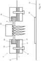
- the window 9 could be supported by a window frame, such as for example a stainless steel window frame, as illustrated in Figure 4 .
- the window frame comprises an external frame part 4 and an internal frame part 5 that fix the hollow 2 to the tray 31 by screws 6.
- a seal 7 is mounted between the internal frame part 5 and the tray 31 for preventing water, air, nitrogen or ozone from flowing inside and/or outside the container 1 through the window frame.
- An additional seal 8 could be mounted on a surface of the internal frame 5 that is dedicated to support the UV light lamp 10. This seal 8 prevents water, air, nitrogen or ozone from flowing inside and/or outside a volume 91 that is formed by the insertion of the irradiation part 13 of the UV lamp 10 inside the hollow 2.
- this volume 91 between the irradiation part 13 of lamp 10 and the window 9 could be flushed with nitrogen gas or other VUV inert gas to reduce oxygen concentration between the lamp and the window 9, and thus the generation of ozone outside the container.
- a support 15 of the lamp 10 could be provided with a first hole 11 cooperating with a tube 14 in order to flush gas into such volume while a second hole 12 of the support 15 guarantees the taking over of such gas.
- a vacuum could be created between the window and the light source.
- the hollow 2 of the Figure 4 could be advantageously comprised in a tray of a closable trolley for surgical instruments.
- the inside contained instruments could be sterilized and stored inside the same trolley inside or near the operating theatre.
- the hollow 2 opens in one side of the tray 31.
- the hollow 2 could open in the lid 3 or in other parts of the container where available.
- the hollow 2 is defined within a dedicated box 150 that is fixed to external surface of the lid 3.
- a wall of this box 150 comprises an UV-transparent window 9, advantageously in form of an UV-transparent plate.
- the box will be positioned on the lid 3 so that the UV-transparent window overlaps a dedicated overture of the lid 3.
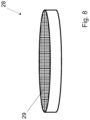
- Figures 6 and 7 illustrate an embodiment wherein the hollow 2 is defined by the frame of a window 9 constituted by a UV-transparent plate 16.
- the window is flat, but could be slightly concave or convex, or planoconcave.
- This embodiment is well adapted for mono-directional UV light sources, such as UV laser sources or extremities of optic fibers that spread light only in one direction.
- the window could act as a lens that diverges the laser beam in order to raise the volume within the container where it interacts with air.
- an additional diverging lens could be used between the light source and the window, or within the container.
- the ozone destruction could be achieved with a UVC or Middle Ultraviolet Laser.
- An UV laser source has the advantage over UV lamps to avoid any manipulation of the lamp; the laser, or the optic fiber, can be plugged to the frame, or maintained at distance of the window, without any need to touch the light source.
- a laser permits to reduce the surface of the transparent window 9 to a tiny surface.
- a less than 20mm diameter window for example a 9mm diameter window 9, could be used in cooperation with a UV laser.
- the laser could be located at a remote distance and the UV rays could be directed to the window 9 by one or a plurality of optic fibers, or through another light path that reduces the generation of ozone in air.
- the window frame supports the window and could be for example a stainless steel window frame.
- the frame comprises an internal frame part 17 and an external frame part 18 defining the hollow 2 and fixed to the tray 31 by screws 6.
- the window frame could also be part of the tray.
- the shape of the external frame part 18 form the hollow 2 that substantially surround an emitting surface of a UV light source, as shown in Figure 11 , in order to avoid or at least to mitigate an outwards direct emission and/or an outwards reflection of UV light on an external surface of the container or of the window.
- a plurality of seals 7, 20, 21 is used for preventing water, air, nitrogen or ozone from flowing inside and/or outside the container 1 through the hollow 2.
- Holding means may be provided in the container 1 for holding the contained objects and preventing it from being moved sterilization and storage operations. Those holding means may further been arranged for preventing UV lights entering into the container for reaching damageable parts of the objects, for example UV-sensitive parts if the objects in the container have some UV sensitive parts.
- the container could be equipped with at least one water tank.
- the role of said tank(s) is to maintain high relative humidity (RH) inside the container to permits an optimal creation of ozonites by UV light irradiation.
- RH relative humidity
- the water tank could be placed and designed in order to retain water from flowing within the container by gravity force, thank to water surface tension.
- cavities or hollows could be placed on the internal, bottom part of the tray and/or in other parts of the container.
- the water tank could contain means for retaining water inside the tank, such as a sponge, foam or other water retaining means for preventing water from flowing within the container.
- the water tank could be covered by a waterproof, breathable fabric such as Gore-Tex ® .
- the water tank could be a disk-shaped tank provided with water retaining means, for example with sponge, placed substantially vertically in the container in order to provide two surfaces of contact between the water and the volume inside the container.
- Figure 9 shows a graphical representation of a sterilization and storage process according to the invention.
- the method of sterilization and storage of medical devices, in particular surgical instruments, placed in said container consists in 10 steps (S1-S10).
- a medical device or devices to sterilize and a water tank are placed in the tray 31 of the container 1.
- a desiccant unit or element could be placed in the tray 31.
- a sterilization indicator such as a rubber with bands that will change color during the sterilization, could be placed at a convenient place inside the container, to be visible through the window. This indicator could be checked at the moment of the container overture in surgery theatre in order to verify the sterilization status of contained medical devices.
- the quantity of water initially retained in the water tank is adapted to such procedure.
- a computer-operated processing unit could be used to determine such quantity, depending on the shape and the volume of such container and the number and type of contained medical devices. This information could be furnished and managed through an identification label provided on an external or internal surface of the container, e.g a code bar label or RFID tag.
- the container is then closed and/or sealed, by example by placing a lid 3 on the tray 31 (S2). If the closable container is a trolley, such container could be airtight closed and/or sealed, by example, by closing all the drawers of such trolley.
- Vacuum Ultraviolet light source 34 An irradiating part of a Vacuum Ultraviolet light source 34 is then placed in a hollow 2 comprising a UV-transparent window 9 of the closed/sealed container 36 (S3).
- a Vacuum Ultraviolet light source 34 could be placed near the hollow 2 having a hollow that is adapted to substantially surround an emitting surface of the Vacuum Ultraviolet light source 34.
- This source irradiates the content of the container through the UV-transparent window 9 of the hollow 2 of the container in order to generate ozone and/or ozonites within said volume (step S4).
- ozone could be created by UV ray with wavelength shorter than 200nm.
- the wavelength of the said light source could be comprised in a range from 130nm to 200nm.
- a computer-operated processing unit could be employed to trigger and control the execution of this step of irradiating the content of the container through the UV-transparent window 9.
- the hollow 2 could be located in the tray or in other parts of the container so that the irradiation of the Vacuum Ultraviolet light source could generate ozone inside the container in an effective and efficient way.
- the window 9 of the hollow 2 is located on the container so that the Vacuum Ultraviolet light source could irradiate inside the closed container for a distance of at least 10 cm.
- the hollow 2 could be located in the tray or in other parts of the container in order to directly irradiate a larger volume inside the container.
- oxygen concentration between the Vacuum Ultraviolet light source and the window 9 could be reduced by creating locally a vacuum situation.
- suction caps and/or air pumps could be employed.
- oxygen could be replaced by another gas, in order to limit the excessive formation of ozone outside of said container.
- Vacuum Ultraviolet light source 34 is then removed from such hollow 2 of the container (S5).
- the incubation time (S6), ozone and ozonites in the tray sterilize the inner content of the tray.
- the incubation time is defined according to the selected Sterilization Assurance Level (SAL).
- SAL Sterilization Assurance Level
- a computer-operated processing unit could be employed to trigger and control the execution of this step of waiting for such incubation time.
- Such incubation time could be managed through an identification label provided on an external surface of the container, e.g. like a code bar label or RFID label.
- the container 1 could be immediately stored after removing the Vacuum Ultraviolet light source (S5) without further operations.
- an irradiating part of an UVC or Middle Ultraviolet light source 35 is then placed in or near the hollow 2 of the closed/sealed container 36 (S7), after waiting for the incubation time.
- This source 35 irradiates the volume inside the sealed container through the window 9 in order to destroy ozone and/or ozonites (step S8).
- Tests have shown that ozone is efficiently destroyed by UV rays with wavelengths from 220nm up to 290nm.
- the wavelength of the said light source could be comprised in a range from 240nm to 280nm.
- Low pressure Hg lamps could be used, as said lamps emit 254nm UV-ray.
- a computer-operated processing unit could be employed to trigger and control the execution of this step ozone and/or ozonites destruction.
- An identification label provided on an external surface of the container could provide the required information for this task.
- the irradiating part of the UVC or Middle Ultraviolet light source 35 is then removed from such hollow 2 (S9).
- the object or objects placed in said sealed container 36 are safely sterilized and ready for use and/or for storage within the container without further packaging procedures (S10). Furthermore, this object or these objects could be further transported or exported in a sterile manner, within the same container used during the sterilization cycle.
- a use of a UV light source adapted to selectively irradiate Vacuum Ultraviolet light and UVC or Middle Ultraviolet light could replace the use of two UV light sources 34 and 35.
- this UV light source could be placed inside or near the hollow 2 once at step S3 and removed in step S9.
- Figure 10 shows a graphical representation of another sterilization process that involves a repetition of ozone and/or ozonite generation, ozone and/or ozonite destruction steps and incubation steps.
- This sterilisation process involves at least a repetition of the steps of:
- Each repetition is preceded by a step of waiting for an incubation time (S11) that will be executed after the step of irradiation with UVC or Middle Ultraviolet light (S7-S8-S9).
- This sterilization procedure could involve a repetition of the insertion of an irradiation part of a Vacuum Ultraviolet light 34 in the hollow 2 (S3) and the successive removing (S5).
- This sterilization procedure could involve a repetition of the insertion of an irradiation part of a UVC or Middle Ultraviolet light 35 in the hollow 2 (S7) and the successive removing (S9).
- an UV light source adapted to selectively irradiate Vacuum Ultraviolet light and UVC or Middle Ultraviolet light could be inserted once inside the hollow at the first execution of the step S3 and removed at the last execution of the step S9.
- the above-mentioned procedures allow a rapid reuse of the UV light sources 34,35 for other procedures. These procedures permit a pipeline-approach of a plurality of parallel sterilization procedures implying the same UV light sources and a plurality of containers of the invention.
- the method of sterilization further comprises an additional step of placing a desiccant inside said container before to seal said container.
- a desiccant like silica gel, could be placed inside the container in order to control humidity after the sterilization process.
- the desiccant is selected so that the desiccating dynamic inside the container doesn't interfere with the humidity distribution and homogeneity provided by the water tank during the sterilization process.
- Ozone measurement system could be used to measure ozone quantities or densities in containers and/or in the sterilization equipment.
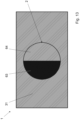
- FIGs 11 and 12 show an example of ozone measurement system that could equip a container according to the invention.
- ozone and/or ozonites could be created by irradiating the inside volume of the container 1 through the UV-transparent window 9 of the hollow 2 by means of a Vacuum UV lamp 24.
- the container is provided by a mirror 22 that is placed on the bottom of the tray 31.
- Ozone/ozonites concentration could be determined by irradiating the inside volume by a 240-280nm wavelength UV lamp and measuring the returning energy of the reflecting rays on said mirror 22.
- a 254nm UV Lamp 25 is used to irradiate the inside volume of the container and a spectrophotometer 27 to measure such energy.
- the window 9 and/or the UV lamp comprises a concave element or another lens, in order to compensate for deviation of the UV rays at the interface between air and such window and to avoid deviation of the rays in undesired directions.
- Figures 13-15 show an embodiment of a container whose hollow 2 is provided with a shutter (63,64).
- the container 1 of this example comprises a tray 31 and a hollow 2.
- the hollow 2 of this embodiment comprises a shutter with an upper pivoting part 63 and a lower and non-pivoting part 64.
- the upper pivoting part could pivot from a closed position ( Figure 13 ) to an open position ( Figure 15 ).
- the inside volume could be irradiated in order to generate ozone and/or ozonites with a vacuum UV lamp. Ozone/ozonites could be destroyed by irradiating the internal volume by a UVC-middle UV lamp.
- the container could be sealed closing by pivoting the upper part 29 of the shutter in a closed position.
- a closable airtight container suitable for storage and sterilization of inside contained medical devices comprises
- a closable airtight container suitable for storage and sterilization of inside contained medical devices comprises:
Landscapes
- Health & Medical Sciences (AREA)
- Epidemiology (AREA)
- Life Sciences & Earth Sciences (AREA)
- Animal Behavior & Ethology (AREA)
- General Health & Medical Sciences (AREA)
- Public Health (AREA)
- Veterinary Medicine (AREA)
- Engineering & Computer Science (AREA)
- Mechanical Engineering (AREA)
- Apparatus For Disinfection Or Sterilisation (AREA)
- Packages (AREA)
Claims (16)
- Un procédé de stérilisation d'un dispositif médical placé dans un récipient pouvant être fermé hermétiquement (1), comprenant les étapes suivantes :a) placer ledit dispositif médical à l'intérieur d'un récipient pouvant être fermé hermétiquement (S1) ;b) fermer ledit récipient (S2) ;c) placer une source de lumière ultraviolette sous vide (34) à une distance comprise entre 0 et 5 cm d'une fenêtre (9) dudit récipient (S3), dans lequel ladite fenêtre (9) est transparente à la lumière ultraviolette sous vide et le reste dudit récipient consiste en matériau non transparent aux ultraviolets ;d) irradier un volume à l'intérieur dudit récipient (36) de lumière ultraviolette sous vide à travers ladite fenêtre (9) afin de générer de l'ozone et/ou des ozonites dans ledit volume (S4) ;e) retirer ladite source de lumière ultraviolette sous vide (S5) ;f) attendre un temps d'incubation (S6).
- Le procédé selon la revendication 1, comprenant en outre les étapes suivantes après ladite étape f) :g) placer une source de lumière UVC ou ultraviolette moyenne (35) contre ladite fenêtre (S7) ;h) irradier ledit volume à l'intérieur dudit récipient avec de la lumière UVC ou ultraviolette moyenne à travers ladite fenêtre (9) afin de détruire l'ozone et/ou les ozonites (S8) ;i) retirer ladite source de lumière UVC ou ultraviolette moyenne (S9).
- Le procédé selon l'une quelconque des revendications 1 ou 2, ledit récipient comprenant un creux (2) pour une source lumineuse,ledit creux (2) incluant ladite fenêtre (9),dans lequel ladite étape c) comprend l'introduction de ladite source de lumière ultraviolette sous vide (34) dans ledit creux.
- Le procédé selon la revendication 3, dans lequel ledit creux (2) est fermé par l'introduction de ladite source de lumière ultraviolette sous vide (34).
- Le procédé de stérilisation selon l'une quelconque des revendications 1 à 4, comprenant en outre une étape consistant à :
m) mesurer la concentration d'ozone/d'ozonites à l'intérieur dudit récipient. - Le procédé de stérilisation selon l'une quelconque des revendications 1 à 5, ledit récipient étant réutilisable, ledit procédé comprenant la répétition des étapes a) à f) au sein du même récipient.
- Le procédé de stérilisation selon l'une quelconque des revendications 1 à 6, comprenant une étape de transport dudit récipient vers un bloc opératoire et d'ouverture dudit récipient dans ledit bloc opératoire afin d'accéder et d'utiliser le dispositif médical stérilisé.
- Un récipient pouvant être fermé hermétiquement (1) pour le stockage et la stérilisation de dispositifs médicaux contenus à l'intérieur, ledit récipient comprenant :une fermeture hermétique pour l'introduction desdits dispositifs médicaux dans ledit récipient (1) et le retrait desdits dispositifs médicaux stérilisés hors dudit récipient (1) ; etune fenêtre (9) transparente à la lumière ultraviolette sous vide ;dans lequel ladite fenêtre (9) s'étend sur une surface extérieure dudit récipient qui représente moins de 25 pour cent de la surface extérieure totale dudit récipient ;dans lequel ladite fenêtre est agencée pour que la lumière ultraviolette sous vide entrant à travers ladite fenêtre dans ledit récipient irradie un volume à l'intérieur dudit récipient afin de générer de l'ozone et/ou des ozonites dans ledit volume qui stérilise lesdits dispositifs médicaux ;tandis que le reste dudit récipient est essentiellement constitué d'un matériau non transparent aux ultraviolets.
- Le récipient hermétique selon la revendication 8, ledit récipient comprenant en outre un creux (2) ; dans lequel ledit creux (2) comprend ladite fenêtre (9) et dans lequel ledit creux (2) est adapté pour entourer au moins partiellement une source de lumière UV (10, 24, 25, 34, 35).
- Le récipient hermétique selon la revendication 8 ou 9, dans lequel ledit reste du récipient est essentiellement réalisé en acier inoxydable, et dans lequel ladite fenêtre (9) est essentiellement réalisée en quartz ou MgF2 ou Al2O3 ou CaF2.
- Le récipient hermétique selon l'une des revendications 8 à 10, dans lequel ledit creux (2) comprend une partie concave (92) avec au moins un côté transparent aux UV adapté pour faire dévier ladite lumière ultraviolette sous vide de sorte à occuper le volume au sein du récipient.
- Le récipient hermétique selon la revendication 11, dans lequel ledit creux (2) est cylindrique, conique ou tubulaire.
- Un agencement comprenant un récipient hermétique selon l'une des revendications 8 à 12, comprenant en outre une source de lumière ultraviolette sous vide (34) adaptée pour une insertion amovible à l'intérieur du creux (2) dudit récipient.
- L'agencement selon la revendication 13, comprenant en outre une source de lumière UVC et/ou ultraviolette moyenne (35) adaptée pour une insertion amovible à l'intérieur dudit creux (2).
- L'agencement selon l'une des revendications 13 ou 14, dans lequel ladite source de lumière ultraviolette sous vide (34) ou ladite source de lumière UVC et/ou ultraviolette moyenne (35) comprend une fixation adaptée pour la fixer de manière amovible audit récipient afin de créer un volume hermétique fermé (91) entre ladite source de lumière et ladite fenêtre.
- L'agencement selon l'une quelconque des revendications 13 à 15, comprenant en outre une unité de traitement commandée par ordinateur adaptée pour déclencher et contrôler l'exécution desdites étapes d), f) et h).
Applications Claiming Priority (2)
| Application Number | Priority Date | Filing Date | Title |
|---|---|---|---|
| CH4082013 | 2013-02-06 | ||
| PCT/EP2014/052367 WO2014122230A1 (fr) | 2013-02-06 | 2014-02-06 | Procédé et agencement pour stérilisation et stockage de dispositifs médicaux |
Publications (2)
| Publication Number | Publication Date |
|---|---|
| EP2953655A1 EP2953655A1 (fr) | 2015-12-16 |
| EP2953655B1 true EP2953655B1 (fr) | 2024-10-16 |
Family
ID=47845658
Family Applications (1)
| Application Number | Title | Priority Date | Filing Date |
|---|---|---|---|
| EP14702890.6A Active EP2953655B1 (fr) | 2013-02-06 | 2014-02-06 | Procédé, récipient et agencement pour stérilisation et stockage de dispositifs médicaux |
Country Status (4)
| Country | Link |
|---|---|
| US (1) | US10874754B2 (fr) |
| EP (1) | EP2953655B1 (fr) |
| GB (1) | GB2523963B (fr) |
| WO (2) | WO2014122226A2 (fr) |
Families Citing this family (18)
| Publication number | Priority date | Publication date | Assignee | Title |
|---|---|---|---|---|
| CA2998327A1 (fr) * | 2015-09-11 | 2017-03-16 | Stryker Corporation | Enceinte de sterilisation pour instruments chirurgicaux |
| DE102016008324A1 (de) * | 2016-07-07 | 2018-01-11 | Lengmo Gmbh | Desinfektionsvorrichtung und Desinfektionsverfahren |
| US10232954B2 (en) | 2016-09-21 | 2019-03-19 | The Boeing Company | Apparatuses and methods for reducing ozone creation from ultraviolet (UV) light |
| CN110740758B (zh) * | 2017-07-07 | 2022-10-11 | 首尔伟傲世有限公司 | 杀菌模块 |
| JP7184683B2 (ja) * | 2019-03-18 | 2022-12-06 | ウシオ電機株式会社 | 除染方法 |
| US11266757B2 (en) | 2019-08-06 | 2022-03-08 | Daniel R. Schumaier | Hearing aid dryer and disinfection kit with UV-reflective drying tray |
| US11122378B1 (en) * | 2019-08-06 | 2021-09-14 | Daniel R. Schumaier | Hearing aid dryer and disinfection kit |
| US11092379B2 (en) | 2019-08-07 | 2021-08-17 | Ear Technology Corporation | Dryer and sanitizer for rechargeable electronic devices |
| DE102019006275A1 (de) * | 2019-09-05 | 2021-03-11 | Daimler Ag | Vorrichtung zur Bestrahlung einer Fläche |
| US11007292B1 (en) | 2020-05-01 | 2021-05-18 | Uv Innovators, Llc | Automatic power compensation in ultraviolet (UV) light emission device, and related methods of use, particularly suited for decontamination |
| EP3915594A1 (fr) * | 2020-05-07 | 2021-12-01 | Lazurtec, Inc. | Outil de stérilisation pour outils dentaires et médicaux et systèmes et procédés associés |
| RU199696U1 (ru) * | 2020-06-25 | 2020-09-15 | Руслан Вячеславович Марущенко | Устройство для бесконтактной передачи материальных объектов |
| US12396554B1 (en) | 2020-07-13 | 2025-08-26 | PURioLABS, LLC | Equipment disinfection cabinet |
| US12263260B1 (en) * | 2020-07-13 | 2025-04-01 | PURioLABS, LLC | Equipment disinfection cabinet |
| USD1066958S1 (en) | 2021-07-13 | 2025-03-18 | PURioLABS, LLC | Cabinet |
| USD1073068S1 (en) | 2022-06-03 | 2025-04-29 | Saban Ventures Pty Limited | Accessory for holding a medical device |
| WO2025024190A2 (fr) * | 2023-07-21 | 2025-01-30 | Steris Corporation | Emballage de stérilisation |
| WO2025035193A1 (fr) * | 2023-08-11 | 2025-02-20 | Fernandes Paulo Roberto Gomes | Plateau |
Family Cites Families (28)
| Publication number | Priority date | Publication date | Assignee | Title |
|---|---|---|---|---|
| US4390432A (en) * | 1979-04-10 | 1983-06-28 | Marui Industry Co., Ltd. | Method of purifying water in fish keeping water tank |
| US4296328A (en) * | 1980-02-11 | 1981-10-20 | Regan Michael D | Apparatus for producing high purity water |
| US5393419A (en) * | 1993-02-10 | 1995-02-28 | Amway Corporation | Ultraviolet lamp assembly for water purification |
| CA2200988A1 (fr) * | 1994-09-27 | 1996-04-04 | Richard Little | Appareil de nettoyage |
| US8048370B1 (en) | 1997-11-21 | 2011-11-01 | Barnes Ronald L | Germicidal generator of ozone and ozonites |
| US6514405B1 (en) * | 1999-08-12 | 2003-02-04 | Eric L. Lifschitz | Portable water purifier with ultraviolet light source |
| WO2001016029A1 (fr) * | 1999-08-31 | 2001-03-08 | Kimberly-Clark Worldwide, Inc. | Systeme de purification portatif |
| US7045096B2 (en) | 2001-12-31 | 2006-05-16 | Argentara Five, Inc. | Sterilization and detoxification of confined spaces |
| AU2003299155A1 (en) * | 2002-10-01 | 2004-04-23 | Next Safety, Inc. | Methods and apparatus for ultraviolet sterilization |
| WO2004062800A1 (fr) | 2003-01-06 | 2004-07-29 | The Johns Hopkins University | Decontamination induite par des radicaux libres hydroxyle de spores, de virus et de bacteries aeriens dans un systeme dynamique |
| IL157229A (en) * | 2003-08-04 | 2006-08-20 | Zamir Tribelsky | Method for energy coupling especially useful for disinfecting and various systems using it |
| EP1586539A1 (fr) * | 2004-04-13 | 2005-10-19 | Araiza, Rafael | Dispositif de traitement d'un milieu liquide et/ou gazeux par radiations uv |
| ITMI20041535A1 (it) * | 2004-07-28 | 2004-10-28 | W & H Sterilization Srl | Autoclave con ambiente a bassa carica batterica e relativo coperchio di serbatoio. |
| US20060130663A1 (en) * | 2004-12-20 | 2006-06-22 | General Electric Company | System and method of air quality control for air-conditioning devices |
| US20080131330A1 (en) * | 2005-01-24 | 2008-06-05 | Uv Light Sciences Group, Inc. | Ultra-Violet Batch Water Treatment and Small Item Sterilization System |
| US20070209957A1 (en) * | 2006-03-09 | 2007-09-13 | Sdgi Holdings, Inc. | Packaging system for medical devices |
| US7372044B2 (en) * | 2006-05-17 | 2008-05-13 | Andrew Ross | UV sterilization of user interface fomites |
| WO2007146699A2 (fr) | 2006-06-06 | 2007-12-21 | Germgard Lighting, Llc | nettoyage de plateau et d'outil |
| KR20140100553A (ko) * | 2006-07-10 | 2014-08-14 | 존슨 앤드 존슨 비젼 케어, 인코포레이티드 | 약제학적 제제를 함유하는 안과용 렌즈를 위한 패키지 |
| WO2008008536A2 (fr) * | 2006-07-14 | 2008-01-17 | United States Postal Service | système de SURVEILLANCE DU fonctionnement |
| US8203124B2 (en) * | 2007-04-27 | 2012-06-19 | Hand Held Products, Inc. | Sterilization apparatus |
| US20090090383A1 (en) * | 2007-10-09 | 2009-04-09 | Alan Ingleson | Method and apparatus for cleaning an integrating sphere |
| US8125333B2 (en) * | 2008-06-04 | 2012-02-28 | Triton Thalassic Technologies, Inc. | Methods, systems and apparatus for monochromatic UV light sterilization |
| US20120056102A1 (en) * | 2008-11-06 | 2012-03-08 | Stanley Kenneth A | Ultraviolet Light Sanitizing Method and Apparatus |
| WO2011094017A2 (fr) * | 2010-01-29 | 2011-08-04 | Shenberg James E | Système d'eau ozonée en bouteille |
| US20130048545A1 (en) * | 2011-08-23 | 2013-02-28 | Maxim S. Shatalov | Water Disinfection Using Deep Ultraviolet Light |
| MX2014006561A (es) * | 2011-12-02 | 2014-09-22 | Aquamost Inc | Aparato y metodo para tratar soluciones acuosas y contaminantes en las mismas. |
| CA2931403C (fr) * | 2012-12-06 | 2020-03-31 | Xenex Disinfection Services, Llc. | Systemes de definition des parametres de fonctionnement et des programmes de desinfection destines a des dispositifs germicides et des appareils a lampes germicides comprenant des systemes de lentille |
-
2014
- 2014-02-06 GB GB1512336.7A patent/GB2523963B/en active Active
- 2014-02-06 WO PCT/EP2014/052361 patent/WO2014122226A2/fr not_active Ceased
- 2014-02-06 WO PCT/EP2014/052367 patent/WO2014122230A1/fr not_active Ceased
- 2014-02-06 EP EP14702890.6A patent/EP2953655B1/fr active Active
- 2014-02-06 US US14/765,292 patent/US10874754B2/en active Active
Also Published As
| Publication number | Publication date |
|---|---|
| CN105102006A (zh) | 2015-11-25 |
| GB201512336D0 (en) | 2015-08-19 |
| EP2953655A1 (fr) | 2015-12-16 |
| US20160008498A1 (en) | 2016-01-14 |
| WO2014122230A1 (fr) | 2014-08-14 |
| US10874754B2 (en) | 2020-12-29 |
| GB2523963B (en) | 2018-06-06 |
| GB2523963A (en) | 2015-09-09 |
| WO2014122226A2 (fr) | 2014-08-14 |
| GB2523963A8 (en) | 2015-09-30 |
| WO2014122226A3 (fr) | 2014-10-23 |
Similar Documents
| Publication | Publication Date | Title |
|---|---|---|
| EP2953655B1 (fr) | Procédé, récipient et agencement pour stérilisation et stockage de dispositifs médicaux | |
| CN106999616B (zh) | 灭菌容器、灭菌的方法和灭菌装置 | |
| US20100270197A1 (en) | Multipurpose packages for sterile products or products to be sterilised | |
| KR20150123165A (ko) | 제약, 의료 또는 화장 물품을 위한 포장 유닛, 및 포장 유닛 내에 배치될 수 있는 제약, 의료 또는 화장 물품의 살균 방법 | |
| US20230226238A1 (en) | A Device for Retaining an Object in a Sterilization/Disinfection Apparatus | |
| JP5603700B2 (ja) | 連続除染、滅菌装置及び方法 | |
| WO2007146699A2 (fr) | nettoyage de plateau et d'outil | |
| JP2005528292A (ja) | 無菌の物体または消毒される物体用の包装容器 | |
| KR102754309B1 (ko) | 컨테이너로부터 격납부 내로의 살균 대상의 오염 없는 도입을 위한 배열체 및 그를 위한 방법 | |
| US20240409262A1 (en) | Method and system for reprocessing reusable medical instruments | |
| Lambert et al. | Chapter III. 1.2—Sterilization of Implants and Devices | |
| CN105102006B (zh) | 用于医疗设备灭菌和储存的方法和装置 | |
| CN115103693A (zh) | 消毒装置以及用于对容器的外表面进行消毒的方法 | |
| Denyer et al. | 21 Sterilization procedures and sterility assurance | |
| US20250065000A1 (en) | UV Light and Hydrogen Peroxide for Sterilization | |
| EP3368453B1 (fr) | Dispositif de décontamination/désinfection pour des supports de transport de récipients, entre autres, et procédé de décontamination et/ou de désinfection de supports | |
| JP7285820B2 (ja) | 遮蔽構造 | |
| CA3164393C (fr) | Dispositif de sterilisation et procede de sterilisation d'une face exterieure d'un recipient | |
| KR102301313B1 (ko) | 미생물 보관용기 자동 살균장치 | |
| Dewhurst et al. | 11 Sterilization Methods |
Legal Events
| Date | Code | Title | Description |
|---|---|---|---|
| PUAI | Public reference made under article 153(3) epc to a published international application that has entered the european phase |
Free format text: ORIGINAL CODE: 0009012 |
|
| 17P | Request for examination filed |
Effective date: 20150730 |
|
| AK | Designated contracting states |
Kind code of ref document: A1 Designated state(s): AL AT BE BG CH CY CZ DE DK EE ES FI FR GB GR HR HU IE IS IT LI LT LU LV MC MK MT NL NO PL PT RO RS SE SI SK SM TR |
|
| AX | Request for extension of the european patent |
Extension state: BA ME |
|
| DAX | Request for extension of the european patent (deleted) | ||
| RAP1 | Party data changed (applicant data changed or rights of an application transferred) |
Owner name: STERILUX SA |
|
| STAA | Information on the status of an ep patent application or granted ep patent |
Free format text: STATUS: EXAMINATION IS IN PROGRESS |
|
| 17Q | First examination report despatched |
Effective date: 20200907 |
|
| GRAP | Despatch of communication of intention to grant a patent |
Free format text: ORIGINAL CODE: EPIDOSNIGR1 |
|
| STAA | Information on the status of an ep patent application or granted ep patent |
Free format text: STATUS: GRANT OF PATENT IS INTENDED |
|
| RIC1 | Information provided on ipc code assigned before grant |
Ipc: B65D 81/00 20060101ALI20240416BHEP Ipc: A61L 2/10 20060101ALI20240416BHEP Ipc: A61L 2/26 20060101AFI20240416BHEP |
|
| INTG | Intention to grant announced |
Effective date: 20240503 |
|
| GRAS | Grant fee paid |
Free format text: ORIGINAL CODE: EPIDOSNIGR3 |
|
| GRAA | (expected) grant |
Free format text: ORIGINAL CODE: 0009210 |
|
| STAA | Information on the status of an ep patent application or granted ep patent |
Free format text: STATUS: THE PATENT HAS BEEN GRANTED |
|
| RIN1 | Information on inventor provided before grant (corrected) |
Inventor name: SPALTENSTEIN, MARC Inventor name: BOYSSET, MAX |
|
| RAP3 | Party data changed (applicant data changed or rights of an application transferred) |
Owner name: STERILUX SA |
|
| RIN1 | Information on inventor provided before grant (corrected) |
Inventor name: SPALTENSTEIN, MARC Inventor name: BOYSSET, MAX |
|
| AK | Designated contracting states |
Kind code of ref document: B1 Designated state(s): AL AT BE BG CH CY CZ DE DK EE ES FI FR GB GR HR HU IE IS IT LI LT LU LV MC MK MT NL NO PL PT RO RS SE SI SK SM TR |
|
| REG | Reference to a national code |
Ref country code: GB Ref legal event code: FG4D |
|
| REG | Reference to a national code |
Ref country code: CH Ref legal event code: EP |
|
| REG | Reference to a national code |
Ref country code: IE Ref legal event code: FG4D |
|
| REG | Reference to a national code |
Ref country code: DE Ref legal event code: R096 Ref document number: 602014091029 Country of ref document: DE |
|
| REG | Reference to a national code |
Ref country code: LT Ref legal event code: MG9D |
|
| REG | Reference to a national code |
Ref country code: NL Ref legal event code: MP Effective date: 20241016 |
|
| REG | Reference to a national code |
Ref country code: AT Ref legal event code: MK05 Ref document number: 1732408 Country of ref document: AT Kind code of ref document: T Effective date: 20241016 |
|
| PG25 | Lapsed in a contracting state [announced via postgrant information from national office to epo] |
Ref country code: NL Free format text: LAPSE BECAUSE OF FAILURE TO SUBMIT A TRANSLATION OF THE DESCRIPTION OR TO PAY THE FEE WITHIN THE PRESCRIBED TIME-LIMIT Effective date: 20241016 |
|
| PG25 | Lapsed in a contracting state [announced via postgrant information from national office to epo] |
Ref country code: NL Free format text: LAPSE BECAUSE OF FAILURE TO SUBMIT A TRANSLATION OF THE DESCRIPTION OR TO PAY THE FEE WITHIN THE PRESCRIBED TIME-LIMIT Effective date: 20241016 |
|
| PG25 | Lapsed in a contracting state [announced via postgrant information from national office to epo] |
Ref country code: IS Free format text: LAPSE BECAUSE OF FAILURE TO SUBMIT A TRANSLATION OF THE DESCRIPTION OR TO PAY THE FEE WITHIN THE PRESCRIBED TIME-LIMIT Effective date: 20250216 Ref country code: PT Free format text: LAPSE BECAUSE OF FAILURE TO SUBMIT A TRANSLATION OF THE DESCRIPTION OR TO PAY THE FEE WITHIN THE PRESCRIBED TIME-LIMIT Effective date: 20250217 Ref country code: HR Free format text: LAPSE BECAUSE OF FAILURE TO SUBMIT A TRANSLATION OF THE DESCRIPTION OR TO PAY THE FEE WITHIN THE PRESCRIBED TIME-LIMIT Effective date: 20241016 |
|
| PG25 | Lapsed in a contracting state [announced via postgrant information from national office to epo] |
Ref country code: FI Free format text: LAPSE BECAUSE OF FAILURE TO SUBMIT A TRANSLATION OF THE DESCRIPTION OR TO PAY THE FEE WITHIN THE PRESCRIBED TIME-LIMIT Effective date: 20241016 |
|
| PG25 | Lapsed in a contracting state [announced via postgrant information from national office to epo] |
Ref country code: BG Free format text: LAPSE BECAUSE OF FAILURE TO SUBMIT A TRANSLATION OF THE DESCRIPTION OR TO PAY THE FEE WITHIN THE PRESCRIBED TIME-LIMIT Effective date: 20241016 |
|
| PG25 | Lapsed in a contracting state [announced via postgrant information from national office to epo] |
Ref country code: ES Free format text: LAPSE BECAUSE OF FAILURE TO SUBMIT A TRANSLATION OF THE DESCRIPTION OR TO PAY THE FEE WITHIN THE PRESCRIBED TIME-LIMIT Effective date: 20241016 |
|
| PG25 | Lapsed in a contracting state [announced via postgrant information from national office to epo] |
Ref country code: NO Free format text: LAPSE BECAUSE OF FAILURE TO SUBMIT A TRANSLATION OF THE DESCRIPTION OR TO PAY THE FEE WITHIN THE PRESCRIBED TIME-LIMIT Effective date: 20250116 |
|
| PG25 | Lapsed in a contracting state [announced via postgrant information from national office to epo] |
Ref country code: AT Free format text: LAPSE BECAUSE OF FAILURE TO SUBMIT A TRANSLATION OF THE DESCRIPTION OR TO PAY THE FEE WITHIN THE PRESCRIBED TIME-LIMIT Effective date: 20241016 Ref country code: GR Free format text: LAPSE BECAUSE OF FAILURE TO SUBMIT A TRANSLATION OF THE DESCRIPTION OR TO PAY THE FEE WITHIN THE PRESCRIBED TIME-LIMIT Effective date: 20250117 Ref country code: LV Free format text: LAPSE BECAUSE OF FAILURE TO SUBMIT A TRANSLATION OF THE DESCRIPTION OR TO PAY THE FEE WITHIN THE PRESCRIBED TIME-LIMIT Effective date: 20241016 |
|
| PGFP | Annual fee paid to national office [announced via postgrant information from national office to epo] |
Ref country code: CH Payment date: 20250301 Year of fee payment: 12 |
|
| PG25 | Lapsed in a contracting state [announced via postgrant information from national office to epo] |
Ref country code: PL Free format text: LAPSE BECAUSE OF FAILURE TO SUBMIT A TRANSLATION OF THE DESCRIPTION OR TO PAY THE FEE WITHIN THE PRESCRIBED TIME-LIMIT Effective date: 20241016 |
|
| PG25 | Lapsed in a contracting state [announced via postgrant information from national office to epo] |
Ref country code: RS Free format text: LAPSE BECAUSE OF FAILURE TO SUBMIT A TRANSLATION OF THE DESCRIPTION OR TO PAY THE FEE WITHIN THE PRESCRIBED TIME-LIMIT Effective date: 20250116 |
|
| PG25 | Lapsed in a contracting state [announced via postgrant information from national office to epo] |
Ref country code: SM Free format text: LAPSE BECAUSE OF FAILURE TO SUBMIT A TRANSLATION OF THE DESCRIPTION OR TO PAY THE FEE WITHIN THE PRESCRIBED TIME-LIMIT Effective date: 20241016 |
|
| PG25 | Lapsed in a contracting state [announced via postgrant information from national office to epo] |
Ref country code: DK Free format text: LAPSE BECAUSE OF FAILURE TO SUBMIT A TRANSLATION OF THE DESCRIPTION OR TO PAY THE FEE WITHIN THE PRESCRIBED TIME-LIMIT Effective date: 20241016 |
|
| REG | Reference to a national code |
Ref country code: DE Ref legal event code: R097 Ref document number: 602014091029 Country of ref document: DE |
|
| PG25 | Lapsed in a contracting state [announced via postgrant information from national office to epo] |
Ref country code: EE Free format text: LAPSE BECAUSE OF FAILURE TO SUBMIT A TRANSLATION OF THE DESCRIPTION OR TO PAY THE FEE WITHIN THE PRESCRIBED TIME-LIMIT Effective date: 20241016 |
|
| PG25 | Lapsed in a contracting state [announced via postgrant information from national office to epo] |
Ref country code: RO Free format text: LAPSE BECAUSE OF FAILURE TO SUBMIT A TRANSLATION OF THE DESCRIPTION OR TO PAY THE FEE WITHIN THE PRESCRIBED TIME-LIMIT Effective date: 20241016 |
|
| PG25 | Lapsed in a contracting state [announced via postgrant information from national office to epo] |
Ref country code: SK Free format text: LAPSE BECAUSE OF FAILURE TO SUBMIT A TRANSLATION OF THE DESCRIPTION OR TO PAY THE FEE WITHIN THE PRESCRIBED TIME-LIMIT Effective date: 20241016 |
|
| PG25 | Lapsed in a contracting state [announced via postgrant information from national office to epo] |
Ref country code: CZ Free format text: LAPSE BECAUSE OF FAILURE TO SUBMIT A TRANSLATION OF THE DESCRIPTION OR TO PAY THE FEE WITHIN THE PRESCRIBED TIME-LIMIT Effective date: 20241016 |
|
| PG25 | Lapsed in a contracting state [announced via postgrant information from national office to epo] |
Ref country code: IT Free format text: LAPSE BECAUSE OF FAILURE TO SUBMIT A TRANSLATION OF THE DESCRIPTION OR TO PAY THE FEE WITHIN THE PRESCRIBED TIME-LIMIT Effective date: 20241016 |
|
| PLBE | No opposition filed within time limit |
Free format text: ORIGINAL CODE: 0009261 |
|
| STAA | Information on the status of an ep patent application or granted ep patent |
Free format text: STATUS: NO OPPOSITION FILED WITHIN TIME LIMIT |
|
| PG25 | Lapsed in a contracting state [announced via postgrant information from national office to epo] |
Ref country code: SE Free format text: LAPSE BECAUSE OF FAILURE TO SUBMIT A TRANSLATION OF THE DESCRIPTION OR TO PAY THE FEE WITHIN THE PRESCRIBED TIME-LIMIT Effective date: 20241016 |
|
| PG25 | Lapsed in a contracting state [announced via postgrant information from national office to epo] |
Ref country code: MC Free format text: LAPSE BECAUSE OF FAILURE TO SUBMIT A TRANSLATION OF THE DESCRIPTION OR TO PAY THE FEE WITHIN THE PRESCRIBED TIME-LIMIT Effective date: 20241016 |
|
| 26N | No opposition filed |
Effective date: 20250717 |
|
| PG25 | Lapsed in a contracting state [announced via postgrant information from national office to epo] |
Ref country code: LU Free format text: LAPSE BECAUSE OF NON-PAYMENT OF DUE FEES Effective date: 20250206 |
|
| REG | Reference to a national code |
Ref country code: BE Ref legal event code: MM Effective date: 20250228 |
|
| PG25 | Lapsed in a contracting state [announced via postgrant information from national office to epo] |
Ref country code: BE Free format text: LAPSE BECAUSE OF NON-PAYMENT OF DUE FEES Effective date: 20250228 |
|
| PG25 | Lapsed in a contracting state [announced via postgrant information from national office to epo] |
Ref country code: IE Free format text: LAPSE BECAUSE OF NON-PAYMENT OF DUE FEES Effective date: 20250206 |
|
| PGFP | Annual fee paid to national office [announced via postgrant information from national office to epo] |
Ref country code: GB Payment date: 20260219 Year of fee payment: 13 |
|
| PGFP | Annual fee paid to national office [announced via postgrant information from national office to epo] |
Ref country code: DE Payment date: 20260218 Year of fee payment: 13 |
|
| PGFP | Annual fee paid to national office [announced via postgrant information from national office to epo] |
Ref country code: FR Payment date: 20260218 Year of fee payment: 13 |